FANUC Series 30i-MODEL A, Series 31i-MODEL A5, Series 31i-MODEL A Workpiece setting error compensation Additional Manual Page 63
Additional Manual
FANUC Series 30i/31i-MODEL A/31i-MODEL A5
Workpiece Setting Error Compensation
A
-79634E
63
/
75
Ed. Date Design Description
Date Feb
.08.’05 Design. Apprv.
page
Title
Draw
No.
19700 Rotary table position (X-axis of the basic three axes)
19701 Rotary table position (Y-axis of the basic three axes)
19702 Rotary table position (Z-axis of the basic three axes)
[Input type] Parameter input
[Data type] Real path
[Unit of data] mm, inch (machine unit)
[Minimum unit of data] Depend on the increment system of the applied axis
[Valid data range] 9 digit of minimum unit of data (refer to standard parameter setting table (A))
(When the increment system is IS-B, -999999.999 to +999999.999)
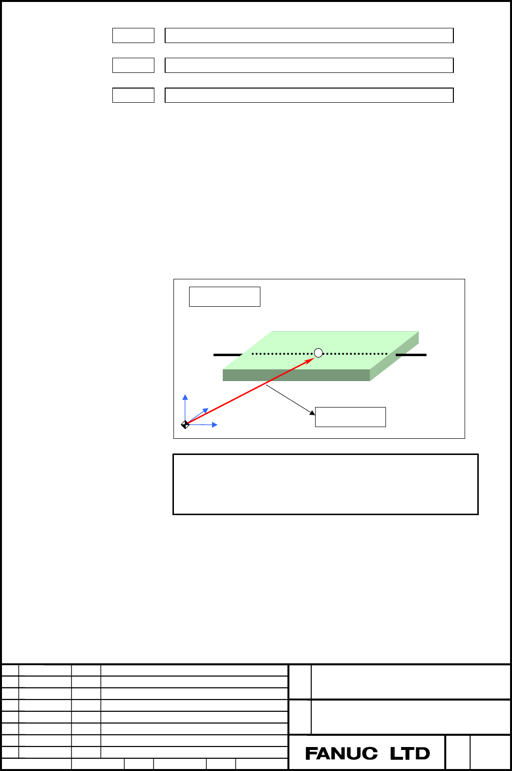
Set these parameters when parameter No. 19680 is set to 12 or 21. The vector
from the origin of the machine coordinate system to point A on the first
rotation axis of the table is set as the rotary table position in the machine
coordinate system.
Rotary table position
Zm
Ym
Xm
First rotary axis o
f
table
Rotary table position
A
NOTE
As point A, set a position that is easy to measure on the first
rotary axis of the table.
Set a radius value.
Contents Summary of FANUC Series 30i-MODEL A, Series 31i-MODEL A5, Series 31i-MODEL A Workpiece setting error compensation Additional Manual
- Page 1FANUC Series 30i-MODEL A FANUC Series 31i-MODEL A5 FANUC Series 31i-MODEL A Specifications for Workpiece Setting Error Compensation FANUC Series 30i/31i-MODEL A/31i-MODEL A5 Title Workpiece Setting Error Compensation Draw A-79634E No. Ed. Date Design Description page 1 / 75 Date Feb.08.’05 Design. A
- Page 2Contents 1.1 WORKPIECE SETTING ERROR COMPENSATION ..........................................................................3 Overview ..............................................................................................................................................................3 Forma
- Page 31.1 WORKPIECE SETTING ERROR COMPENSATION Overview When a workpiece is placed on the machine, the workpiece is not always placed at an ideal position. With this function, a displaced workpiece can be machined according to the program without making modifications to the program. This function can comp
- Page 4Format G54.4 Pn ; Start workpiece setting error compensation : Workpiece setting error compensation mode : G54.4 P0 ; Cancel workpiece setting error compensation Pn : Workpiece setting error specification code n : 1 to 7 A start block and cancellation block for workpiece setting error compensation s
- Page 5Explanation - Workpiece setting error A workpiece setting error is defined by the following eight variables: - X direction error ∆x - Y direction error ∆y - Z direction error ∆z - Rotation direction error ∆a (rotation error on the X-axis in degrees) - Rotation direction error ∆b (rotation error on t
- Page 6[About ∆a, ∆b, and ∆c] ∆a, ∆b, and ∆c are defined as described below. The workpiece coordinate system obtained by rotating a workpiece coordinate system about the X-axis by angle ∆a, about the Y-axis by angle ∆b, and about the Z-axis by angle ∆c then shifting that workpiece coordinate system by (∆x,
- Page 7The example of Fig. 2 assumes that ∆a = ∆b = 0 and ∆c represents a nonzero value. [About table rotation axis position 1 and table rotation axis position 2] The table rotation axis position means the machine coordinate on the table rotation axis of a 5-axis machine with a table rotation axis (machine
- Page 8- Setting of a workpiece setting error on the workpiece setting error setting screen A workpiece setting error is set on the workpiece setting error setting screen. The workpiece setting error setting screen is displayed according to the procedure below. 1. Press the function key . 2. Press the chap
- Page 9In data setting, the following soft keys can be used. - When you press [NO. SRH] after entering a workpiece setting error number to be displayed, the screen for setting the desired workpiece setting error is displayed. - When you enter a numeric value then press [+INPUT], the value is added. - When
- Page 10If the setting of table rotation axis position 1/table rotation axis position 2 differs between the workpiece setting error of No. 00 and each workpiece setting error when a 5-axis machine (machine of table rotation type or composite type) with table rotation axes is used, no simple additions are ma
- Page 11When the workpiece setting error of No. 01 is selected, workpiece setting error compensation is performed as follows based on the converted error values based on C = 0.000: ∆x = 10.000+0.000 = 10.000 ∆y = 0.000+5.000 = 5.000 ∆c = 2.000 Y Y' X' ∆c positive direction 2° 5 X 10 C=0 Δx = 10.000, Δy = 5.
- Page 12- Least input increment of data and valid data range [About errors ∆x, ∆y, and ∆z] The unit of data is the unit of input, and follows the least input increment for the reference axis specified by parameter No. 1031. - For metric input Unit system of IS-A IS-B IS-C IS-D IS-E reference axis Least inpu
- Page 13[About table rotation axis position 1 and table rotation axis position 2] The unit of data follows the least input increment of each corresponding rotation axis. Unit system of IS-A IS-B IS-C IS-D IS-E rotation axis Least input 0.01 0.001 0.0001 0.00001 0.000001 increment (deg) Maximum ±999,999.99 ±
- Page 14- Setting of workpiece setting errors with custom macro variables By using custom macro variables #26000 to #26077, workpiece setting errors can be read and written. (The custom macro option is required.) The numbers of macro variables correspond to Errors as follows : error error error error error
- Page 15- Workpiece setting error compensation mode By specifying G54.4 Pn (n: 1 to 7), the workpiece setting error compensation mode can be set. With Pn, select a workpiece setting error from No. 01 to No. 07. In the workpiece setting error compensation mode, the program is executed in a "workpiece setting
- Page 16- Tool direction compensation on a 5-axis machine With a 5-axis machine, tool direction compensation can be performed by setting bit 0 (RCM) of parameter No. 11200 to 1. This means that rotation axis position compensation is performed to direct the tool as programmed relative to the workpiece. For t
- Page 17In the case that bit 0 (RCM) of parameter No. 11200 is 1, Workpiece setting error compensation must be commanded after AICC(AI contouring control) is already active.(G05.1 Q1 is commanded or the parameter SHP(No.1604#0) is 1.) And, the following parameters for Acc/Deceleration are needed. Parameter
- Page 18NOTE 1 If any of the parameters above is set incorrectly when bit 0 (RCM) of parameter No. 11200 is set to 1, alarm PS0438 is issued. 2 Depending on the machine configuration, it may be physically impossible to orient the tool in the compensation direction. In such a case, alarm DS0030 is issued. 3
- Page 19If linear interpolation or circular interpolation is specified on a machine of table rotation type or composite type, linear interpolation or circular interpolation is performed as viewed from the workpiece on the table.
The machine is a table rotation type with A axis(master axis) around - Page 20- "Rotation axis closer to the tool" and "rotation axis closer to the workpiece" on a 5-axis machine When tool direction compensation is performed on a 5-axis machine, a singular point and singular point posture need to be considered. Here, a "rotation axis closer to the tool" and "rotation axis clo
- Page 21- Singular point and singular point posture on a 5-axis machine A tool posture is uniquely determined when the angles of the two rotation axes are determined. Usually, however, a combination of the angles of the two rotation axes for achieving a certain tool posture is not determined uniquely. In pa
- Page 22- Conditions to decide that Tool is in singular posture When the angle between the tool and the singular posture is less than the parameter No.11204, it is decided that the tool is in singular posture. In the descriptions below, the description ‘when the tool is in singular…’ means that ‘it is decid
- Page 23- When the tool posture is closer to a singular point posture on a 5-axis machine If tool direction compensation is performed on a 5-axis, and the tool posture gets closer to a singular point posture during execution of a block, the rotation axis closer to the workpiece may make a large motion. And,
- Page 24The following is an example that the movement direction(area) depends on where the tool firstly exists in comparison with the singular position. The Master axis is C axis around Z axis, and the Slave axis is B axis around Y axis(when C=0). Tool direction is +Z when B=C=0. Here, suppose B axis’ movab
- Page 25When B=0, the tool posture does not change even if C axis moves. That means the position B=0 is singular position. Singular position - 45deg 0deg 100deg B axis movable range Firstly, suppose the following program without Workpiece setting error. Program without Workpiece setting error O1 N10 G5.1 Q1
- Page 26Z N50 end Y B C Absolute 90.0 90.0 Machine 90.0 90.0 X At N50, Machine position moves to B90.0 and C90.0, as commanded. Next, suppose there is the error -2.0deg around Y axis and Workpiece setting error ∆b=-2.000 is set, and the block N25 is added as follows : On O2, B axis position is –1.0 before W
- Page 27Z N40 end Y B C Absolute 1.0 0.0 Machine -1.0 0.0 X Z In the middle of N50 Y X During N50, Machine position does not pass the singular position at all. So, B axis moves from the starting position(–1.0) to the position(B–90.0,C–90.0). As the result, B axis moves over the lower limit of B axis movable
- Page 28O3 N10 G5.1 Q1 N20 G90 G01 B1.0 C0 F1000 ; B axis machine position is between the upper limit and the singular position N25 G54.4 P1 N30 G43.4 H1 N40 X0 Y0 Z0 N50 B90.0 C90.0 Z N40 end Y B C Absolute 3.0 0.0 Machine 1.0 0.0 X Z In the middle of N50 Y X FANUC Series 30i/31i-MODEL A/31i-MODEL A5 Title
- Page 29Z N50 end Y B C Absolute 90.0 90.0 Machine 90.0 90.0 X This time, Machine position moves to B90.0,C90.0. As the result, B axis does not move over the lower limit of B axis movable range. In O2, the case that B axis moves over the limit of movable range is the case that Machine position does not pass
- Page 30Z N40 end Y B C Absolute 1.0 0.0 Machine -1.0 0.0 X Z In the middle of N50 Y X Z N50 end Y B C Absolute 90.0 90.0 Machine 90.0 90.0 X At N50, the machine position moves to B90.0,C90.0. As the result, B axis does not move over the lower limit of B axis movable range. FANUC Series 30i/31i-MODEL A/31i-
- Page 31- Absolute position display Whether absolute coordinates in the workpiece setting error mode are to be displayed in the workpiece coordinate system or workpiece setting coordinate system can be chosen by using bit 6 (DAK) of parameter No. 3106. - Rapid traverse rate for hole machining in a hole mach
- Page 32Examples Example 1 O1 represents a program that cuts each side of a square. O1; N10 G55 ; Set coordinate system N20 G90 G00 X0 Y0 Z300.0 B0 C0 ; Move to initial position N30 G01 G43 H01 Z40.0 F500. ; Start tool length compensation H01 is tool length compensation number. N40 X50.0 Y50.0 Z20.0 ; Z-axi
- Page 33Suppose that the workpiece is displaced from the "correct workpiece setting position" as shown in Fig. 6. Displaced workpiece. Correct workpiece setting position Operation is performed to Y' cut four sides. Y N70 Δc =-20.000 N80 Workpiece N60 N50 Δy =20.000 X Δx =10.000 X' Workpiece coordinate syste
- Page 34To validate the workpiece setting error, add N15 and N115 to O1 as indicated below. O1; N10 G55 ; Set coordinate system N15 G54.4 P1 Workpiece setting error compensation mode ON N20 G90 G00 X0 Y0 Z300.0 B0 C0 ; Move to initial position N30 G01 G43 H01 Z40.0 F500. ; Start tool length compensation H01
- Page 35Example 2 O2 is a program for cutting each side of a square by using tool center point control. The machine is of tool rotation type, the C-axis is the master rotation axis and rotates about the Z-axis, and the B-axis is the slave axis and rotates about the Y- axis. For cutting on the plane normal t
- Page 36Suppose that the workpiece is displaced from the correct workpiece setting position as with example 1, and set a workpiece setting error in the same was as in Example 1. Moreover, add N15,N16,N135 and N136 to O2 as indicated below to validate the workpiece setting error as in the case of Example 1.
- Page 37Displaced workpiece. Operation is performed to Y cut four sides. Y' Correct workpiece N90 setting position N110 Workpiece N70 N50 X X' Workpiece coordinate system XYZ Workpiece setting coordinate system X'Y'Z' Fig. 8 Operation of tool center point control when there is a workpiece setting error FANU
- Page 38Restrictions (general) - Specifiable G codes When workpiece setting error compensation is enabled, the G codes listed below can be specified. If a G code not listed below is specified, alarm PS0437 is issued. G00 Positioning G01 Linear interpolation G02 Circular interpolation (CW) G03 Circular inter
- Page 39G65 Custom macro call G66 Custom macro modal call G67 Custom macro modal call cancel G68 Coordinate system rotation/three-dimensional coordinate conversion G68.2 Tilted working plane command G73, G74, G76, G80 to G89 Hole machining canned cycle M G45 Tool offset expansion G46 Tool offset reduction G
- Page 40- Modal G codes usable when workpiece setting error compensation is specified In a modal G code state listed below, workpiece setting error compensation can be specified. If workpiece setting error compensation is specified in a modal state not listed below, alarm PS0439 is issued. G00 Positioning G
- Page 41T G69 Mirror image for double turret OFF/balanced cutting mode cancel G69.1 Coordinate system rotation/three-dimensional coordinate conversion/tilted working plane command cancel G90 Absolute programming (for G code system B and C) G91 Incremental programming (for G code system B and C) G94 Feed per
- Page 42- PMC axis control If PMC axis control is exercised in the workpiece setting error compensation mode, workpiece setting error compensation is not applied to movement based on PMC axis control. - Movement of start-up and cancel of Tool length offset When Tool length offset(including Tool center point
- Page 43- Mirror image If workpiece setting error compensation and programmable mirror image are used at the same time, programmable mirror image is applied to the coordinates in the workpiece setting coordinate system, then workpiece setting error compensation is applied. Y Programmed path X' Y' Actual pat
- Page 44- Stroke limit check before movement In the mode of Workpiece setting error compensation, Stroke limit check before movement is not available. - Feedrate override When tool direction is compensated (Parameter RCM (No.11200#0)=1), the tool direction is compensated to the movement which is modified by
- Page 45Restrictions (only with a 5-axis machine) Particularly when tool direction compensation is performed with a 5-axis machine of rotation table type or composite type (when bit 0 (RCM) of parameter No. 11200 is set to 1), the restrictions described below are imposed in addition to "Restrictions (genera
- Page 46- Modal G codes not usable when workpiece setting error compensation is specified Among the "Modal G codes usable when workpiece setting error compensation is specified" in "Restrictions (general)" above, the G codes listed below must not be specified with a 5-axis machine of table rotation type or
- Page 47- Feedrate during Workpiece setting error compensation In the case that Workpiece setting error compensation is done on a table rotation type machine or combination type machine, a process similar to Tool center point control is treated so that movements on the table is controlled. Then, movements o
- Page 48Parameters #7 #6 #5 #4 #3 #2 #1 #0 3106 DAK [Input type] Setting input [Data type] Bit #6 DAK Specifies whether to display coordinates in the program coordinate system or workpiece coordinate system as absolute coordinates when the three-dimensional coordinate conversion mode or the tilted working p
- Page 49Rapid traverse rate for a drilling cycle in the three-dimensional coordinate 5412 conversion mode [Input type] Parameter input [Data type] Realpath [Unit of data] mm/min, inch/min, degree/min (machine unit) [Minimum unit of data]Depend on the increment system of the reference axis [Valid data range]
- Page 50The number of decimal places of rotation direction errors in workpiece 11201 setting error compensation [Input type] Setting input [Data type] Byte path [Valid data range] 0-8 This parameter sets the number of decimal places of rotation direction errors in workpiece setting error compensation. Param
- Page 51Override for maximum cutting feedrate during workpiece setting error 11202 compensation mode [Input type] Parameter input [Data type] Byte path [Unit of data] % [Valid data range] 0 to 100 When the parameter RCM(No.11200#0)=1 in order to enable tool direction compensation, during workpiece setting e
- Page 5211204 Angle to decide singular posture (for Workpiece setting error compensation) [Input type] Parameter input [Data type] Real path [Unit of data] Degree [Minimum unit of data] Depend on the increment system of the reference axis [Valid data range] 9 digit of minimum unit of data (refer to standard
- Page 5319680 Mechanical unit type [Input type] Parameter input [Data type] Byte path [Valid data range] 0 to 21 Specify the type of the mechanical unit. Mechanical Controlled rotation PRM19680 Master and slave unit type axis Mechanism having no 0 rotation axis The first rotation axis is the Tool rotation T
- Page 5419681 Controlled-axis number for the first rotation axis [Input type] Parameter input [Data type] Byte path [Valid data range] 0 to Number of controlled axes in each path Set the controlled-axis number (in each path) for the first rotation axis. For a hypothetical axis (when bit 0 (IA1) of parameter
- Page 5519682 Axis direction of the first rotation axis [Input type] Parameter input [Data type] Byte path [Valid data range] 1 to 6 Specify the axis direction of the first rotation axis. 1: On X-axis 2: On Y-axis 3: On Z-axis 4: On an axis tilted a certain angle from the X-axis from the positive X-axis to
- Page 5619683 Inclination angle when the first rotation axis is an inclined axis [Input type] Parameter input [Data type] Real path [Unit of data] Degree [Minimum unit of data] The increment system of the reference axis is to be followed. [Valid data range] Nine digits of the least input increment (see stan
- Page 5719684 Rotation direction of the first rotation axis [Input type] Parameter input [Data type] Byte path [Valid data range] 0 to 1 Set the direction in which the first rotation axis rotates as a mechanical motion when a positive move command is issued. 0: Clockwise direction as viewed from the negativ
- Page 5819687 Axis direction of the second rotation axis [Input type] Parameter input [Data type] Byte path [Valid data range] 1 to 6 Specify the axis direction of the second rotation axis. 1: On X-axis 2: On Y-axis 3: On Z-axis 4: On an axis tilted a certain angle from the X-axis from the positive X-axis t
- Page 5919689 Rotation direction of the second rotation axis [Input type] Parameter input [Data type] Byte path [Valid data range] 0 to 1 Set the direction in which the second rotation axis rotates as a mechanical motion when a positive move command is issued. 0: Clockwise direction as viewed from the negat
- Page 60#7 #6 #5 #4 #3 #2 #1 #0 19696 IA2 IA1 [Input type] Parameter input [Data type] Bit path #0 IA1 0: The first rotation axis is an ordinary rotation axis. 1: The first rotation axis is a hypothetical axis. If IA1 is 1, set 0 as the controlled-axis number for the first rotation axis (parameter No. 19681
- Page 6119697 Reference tool axis direction [Input type] Parameter input [Data type] Byte path [Valid data range] 1 to 3 Set the tool axis direction in the machine coordinate system when the rotation axes for controlling the tool are all at 0 degrees. Also, set the tool axis direction in the machine coordin
- Page 6219698 Angle when the reference tool axis direction is tilted (reference angle RA) 19699 Angle when the reference tool axis direction is tilted (reference angle RB) [Input type] Parameter input [Data type] Real path [Unit of data] Degree [Minimum unit of data] Depend on the increment system of the re
- Page 6319700 Rotary table position (X-axis of the basic three axes) 19701 Rotary table position (Y-axis of the basic three axes) 19702 Rotary table position (Z-axis of the basic three axes) [Input type] Parameter input [Data type] Real path [Unit of data] mm, inch (machine unit) [Minimum unit of data] Depe
- Page 64Intersection offset vector between the first and second rotation axes of the 19703 table (X-axis of the basic three axes) Intersection offset vector between the first and second rotation axes of the 19704 table (Y-axis of the basic three axes) Intersection offset vector between the first and second
- Page 65Alarms and messages No. Message Description PS0436 ILLEGAL PARAMETER IN WSC The parameter for workpiece setting error compensation is not set correctly. - The three basic axes are not set in parameter No. 1022. PS0437 ILLEGAL COMMAND IN WSC An incorrect command is specified for workpiece setting err
- Page 66No. Message Description PS5421 ILLEGAL COMMAND IN An illegal command was specified in tool center point G43.4/G43.5 control. - A rotation axis command was specified in tool center point control (type 2) mode. - With a table rotary type or mixed-type machine, a I,J,K command was specified in the tool
- Page 671.2 Improvement of the 3-Dimensional Coordinate System Conversion/Tilted Working Plane Command Overview It has become possible to use the 3-dimensional coordinate system conversion/tilted working plane command and tool center point control for 5-axis machining at the same time. In this case, the too
- Page 68Description - Combination with tool center point control for 5-axis machining It is possible to use the 3-dimensional coordinate system conversion/tilted working plane command and tool center point control for 5-axis machining at the same time. To do this, first specify the 3-dimensional coordinate
- Page 69Example: Consider the operation of the rotary axes when the following program is executed in a machine with master rotary axis C about the Z-axis and slave rotary axis B about the Y-axis. N10 G90 G00 B45.0 C-90.0 Assume that B and C was located in this : position initially. N50 G68.2 X100.0 Y0 Z0 I9
- Page 70NOTE 1 The parameter RCM(No.11200#0) must be 1. Otherwise, the alarm PS5421 occurs. 2 Depending on the machine configuration, it is physically impossible to turn the tool to the converted direction. In this case, alarm DS0030 occurs. 3 The start block for tool center point control changes the coordi
- Page 71Parameters #7 #6 #5 #4 #3 #2 #1 #0 5006 TOS [Input type] Parameter input [Data type] Bit #6 TOS Set a tool length compensation operation. 0: Tool length compensation is performed by an axis movement. 1: Tool length compensation is performed by shifting the coordinate #7 #6 #5 #4 #3 #2 #1 #0 11200 RC
- Page 72Override for maximum cutting feedrate during workpiece setting error 11202 compensation mode [Input type] Parameter input [Data type] Byte path [Unit of data] % [Valid data range] 0 to 100 When the parameter RCM(No.11200#0)=1 in order to enable tool direction compensation, during workpiece setting e
- Page 7311204 Angle to decide singular posture (for Workpiece setting error compensation) [Input type] Parameter input [Data type] Real path [Unit of data] Degree [Minimum unit of data] Depend on the increment system of the reference axis [Valid data range] 9 digit of minimum unit of data (refer to standard
- Page 74Alarms and messages No. Message Description PS0438 ILLEGAL PARAMETER IN TOOL When a setting is made to perform tool direction DIRC CMP compensation in workpiece setting error compensation on a 5-axis machine (when bit 0 (RCM) of parameter No. 11200 is set to 1), another parameter is not set correctl
- Page 75No. Message Description PS5421 ILLEGAL COMMAND IN An illegal command was specified in tool center point G43.4/G43.5 control. - A rotation axis command was specified in tool center point control (type 2) mode. - With a table rotary type or mixed-type machine, a I,J,K command was specified in the tool