Spindle Learning Control Manual Additional Manual Page 22
Additional Manual
22/22
Design.
DateEd.
2002.05.06
SHEET
DRAW. No.
CUST.
TITLE
M.Niwa
Newly preparation
Spindle Learning Control Description
A-53866E-0425
FANUC LTD
01
speed
command
(min
-1
)
actual
speed
command
(min
-1
)
learnin
g
period
(0.5ms)
speed
command
(min
-1
)
actual
speed
command
(min
-1
)
learnin
g
period
(0.5ms)
speed
command
(min
-1
)
actual
speed
command
(min
-1
)
learnin
g
period
(0.5ms)
639~641 638.30 188 938~944 937.50 128 1765~1791 1764.71 68
642~645 641.71 187 945~952 944.88 127 1792~1818 1791.04 67
646~648 645.16 186 953~959 952.38 126 1819~1846 1818.18 66
649~652 648.65 185 960~967 960.00 125 1847~1874 1846.15 65
653~655 652.17 184 968~975 967.74 124 1875~1904 1875.00 64
656~659 655.74 183 976~983 975.61 123 1905~1935 1904.76 63
660~662 659.34 182 984~991 983.61 122 1936~1967 1935.48 62
663~666 662.98 181 992~999 991.74 121 1968~1999 1967.21 61
667~670 666.67 180 1000~1008 1000.00 120 2000~2033 2000.00 60
671~674 670.39 179 1009~1016 1008.40 119 2034~2068 2033.90 59
675~677 674.16 178 1017~1025 1016.95 118 2069~2105 2068.97 58
678~681 677.97 177 1026~1034 1025.64 117 2106~2142 2105.26 57
682~685 681.82 176 1035~1043 1034.48 116 2143~2181 2142.86 56
686~689 685.71 175 1044~1052 1043.48 115 2182~2222 2181.82 55
690~693 689.66 174 1053~1061 1052.63 114 2223~2264 2222.22 54
694~697 693.64 173 1062~1071 1061.95 113 2265~2307 2264.15 53
698~701 697.67 172 1072~1081 1071.43 112 2308~2352 2307.69 52
702~705 701.75 171 1082~1090 1081.08 111 2353~2399 2352.94 51
706~710 705.88 170 1091~1100 1090.91 110 2400~2448 2400.00 50
711~714 710.06 169 1101~1111 1100.92 109 2449~2499 2448.98 49
715~718 714.29 168 1112~1121 1111.11 108 2500~2553 2500.00 48
719~722 718.56 167 1122~1132 1121.50 107 2554~2608 2553.19 47
723~727 722.89 166 1133~1142 1132.08 106 2609~2666 2608.70 46
728~731 727.27 165 1143~1153 1142.86 105 2667~2727 2666.67 45
732~736 731.71 164 1154~1165 1153.85 104 2728~2790 2727.27 44
737~740 736.20 163 1166~1176 1165.05 103 2791~2857 2790.70 43
741~745 740.74 162 1177~1188 1176.47 102 2858~2926 2857.14 42
746~749 745.34 161 1189~1199 1188.12 101 2927~2999 2926.83 41
750~754 750.00 160 1200~1212 1200.00 100 3000~3076 3000.00 40
755~759 754.72 159 1213~1224 1212.12 99 3077~3157 3076.92 39
760~764 759.49 158 1225~1237 1224.49 98 3158~3243 3157.89 38
765~769 764.33 157 1238~1249 1237.11 97 3244~3333 3243.24 37
770~774 769.23 156 1250~1263 1250.00 96 3334~3428 3333.33 36
775~779 774.19 155 1264~1276 1263.16 95 3429~3529 3428.57 35
780~784 779.22 154 1277~1290 1276.60 94 3530~3636 3529.41 34
785~789 784.31 153 1291~1304 1290.32 93 3637~3749 3636.36 33
790~794 789.47 152 1305~1318 1304.35 92 3750~3870 3750.00 32
795~799 794.70 151 1319~1333 1318.68 91 3871~3999 3870.97 31
800~805 800.00 150 1334~1348 1333.33 90 4000~4137 4000.00 30
806~810 805.37 149 1349~1363 1348.31 89 4138~4285 4137.93 29
811~816 810.81 148 1364~1379 1363.64 88 4286~4444 4285.71 28
817~821 816.33 147 1380~1395 1379.31 87 4445~4615 4444.44 27
822~827 821.92 146 1396~1411 1395.35 86 4616~4799 4615.38 26
828~833 827.59 145 1412~1428 1411.76 85 4800~4999 4800.00 25
834~839 833.33 144 1429~1445 1428.57 84 5000~5217 5000.00 24
840~845 839.16 143 1446~1463 1445.78 83 5218~5454 5217.39 23
846~851 845.07 142 1464~1481 1463.41 82 5455~5714 5454.55 22
852~857 851.06 141 1482~1499 1481.48 81 5715~5999 5714.29 21
858~863 857.14 140 1500~1518 1500.00 80 6000 6000.00 20
864~869 863.31 139 1519~1538 1518.99 79
870~875 869.57 138 1539~1558 1538.46 78
876~882 875.91 137 1559~1578 1558.44 77
883~888 882.35 136 1579~1599 1578.95 76
889~895 888.89 135 1600~1621 1600.00 75
896~902 895.52 134 1622~1643 1621.62 74
903~909 902.26 133 1644~1666 1643.84 73
910~916 909.09 132 1667~1690 1666.67 72
917~923 916.03 131 1691~1714 1690.14 71
924~930 923.08 130 1715~1739 1714.29 70
931~937 930.23 129 1740~1764 1739.13 69
Contents Summary of Spindle Learning Control Manual Additional Manual
- Page 1FANUC AC SPINDLE MOTOR αi series Spindle Learning Control Description 1. General ................................................................................................................................................. 2 1.1. Overview..........................................................
- Page 21. General 1.1. Overview This manual describes methods for applying Spindle Learning Control for reducing periodic synchronous error between master and slave axes in gear cutting process. See “90A3 / 90A7 / 90B3 / 90B7 Learning Control Operator’s Manual : A-63696E-070” for detailed explanation of Le
- Page 32.1.2. Example 1 : in case of direct drive system velocity and position sensor Built-in spindle motor CNC 1st spindle (master axis) Series 16i/160i/160is JA7B JYA2 18i/180i/180is MODEL B SPM TYPE B JA7A JX4 velocity and position sensor communication between SPMs Built-in spindle motor JX4 JA7B JYA2
- Page 42.1.3. Example 2 : in case of full-closed system with gear reduction velocity sensor Spindle motor CNC 1st spindle (master axis) Series 16i/160i/160is Spindle JA7B JYA2 18i/180i/180is shaft MODEL B SPM external TYPE B position sensor JA7A JYA4 JX4 velocity sensor communication between SPMs Spindle m
- Page 52.1.4. Example 3 : In case of semi-closed system with gear reduction velocity and position sensor Spindle motor CNC 1st spindle (master axis) Series 16i/160i/160is Spindle JA7B JYA2 18i/180i/180is external shaft MODEL B SPM one-rotation TYPE B signal (proximity switch) JA7A JYA3 JX4 velocity and pos
- Page 62.2. Software configuration 2.2.1. Spindle software Software series / edition note Series 9D50 edition E(05) or later for induction motor control Series 9D53 edition B(02) or later for synchronous motor control 2.2.2. CNC software Software series / edition note Series B0H1 edition R(18) or later for
- Page 73. Block diagram CNC 2nd Spindle position feedback velocity feedback - - Slave Helical + + position + velocity spindle movement controller controller & command ( Gain Kp2 ) + + + Sensor No.4069~4072 Learning Learning period controller Feedforward (coefficient α2) No.4036 K2 Synchronous ratio K1 No.4
- Page 84. Input / Output Signals (CNC ↔ PMC) 4.1. Input signal (PMC → CNC) address #7 #6 #5 #4 #3 #2 #1 #0 G073 LCMODA G077 LCMODB LCMODA : Learning Control request signal (for 1st spindle) LCMODB : Learning Control request signal (for 2nd spindle) 0 : Disables Learning Control 1 : Enables Learning Control
- Page 95. Example of sequence master : 1st spindle, master axis of Spindle EGB control master axis speed command slave : 2nd spindle, slave axis of Spindle EGB control slave axis speed command synchoronization synchoronization start by G81 finish by G80 SYNMOD (F65#6) LCVARA (F48#5) LCMODA (G73#6) LCMODB (
- Page 106. Parameters 6.1. Parameters related to sensors *See “FANUC AC SPINDLE MOTOR αi series PARAMETER MANUAL : B-65280EN” for more information about sensor settings. Parameter No. 4000 ROTA1 #7 #6 #5 #4 #3 #2 #1 #0 ROTA1 : Relationship between the rotation direction of spindle and spindle motor. Paramet
- Page 11Parameter No. 4056 Gear ratio (HIGH) CTH1A=0, CTH2A=0 4057 Gear ratio (MEDIUM HIGH) CTH1A=0, CTH2A=1 4058 Gear ratio (MEDIUM LOW) CTH1A=1, CTH2A=0 4059 Gear ratio (LOW) CTH1A=1, CTH2A=1 data unit : Motor rotation for one rotation of spindle × 100 (In case of No.4006#1=1, motor rotation × 1000) data
- Page 126.2. Parameters related to position loop control for constant velocity command in PMC axis control *Master axis (1st spindle) must be driven by this function in Cs contouring mode when Spindle Learning Control function is used. *See “FANUC Series 16i / 18i SPECIFICATIONS FOR POSITION LOOP CONTROL FO
- Page 136.3. Parameters related to Spindle EGB control function *See “FANUC Series 16i / 18i -MA Spindle electronic gear box Specifications : A-77833E” for more information about Spindle EGB Control. *CNC software option is required to use Spindle EGB Control function 6.3.1. Parameters related to serial spi
- Page 14Parameter No. 4386 Gear teeth number of spindle sensor of master axis data unit : 1λ / rev data range : 0, 64 ~ 4096 This data is used to set the gear teeth number of spindle sensor of master axis. When this parameter is set to “0”, synchronous ratio “0” is assumed. *This parameter is valid only for
- Page 156.3.2. Parameters related to synchronous control Parameter No. 7700 HDR HBR #7 #6 #5 #4 #3 #2 #1 #0 HDR : Setting of the synchronization cancellation by reset HBR : Setting of the direction for helical gear compensation Parameter No. 7703 LFS #7 #6 #5 #4 #3 #2 #1 #0 LFS : Setting of the position com
- Page 166.4. Parameters related to Spindle Learning Control Parameter No. 4015 LRNFNC #7 #6 #5 #4 #3 #2 #1 #0 LRNFNC : Function bit of Learning Control 0 : Learning Control is invalid 1 : Learning Control is valid *CNC software option is required to use this function. This bit is automatically set by CNC so
- Page 17Parameter No. 4431 Duration of learning : LCTIME data unit : 0.1sec data range : 0 ~ 32767 This data is used to set duration of Learning Control. Learning controller stops update of compensation data after the expiration of the time interval that this parameter specifies (See following figure). If “
- Page 187. Diagnosis related to Spindle EGB Control Address Description Unit 716 Synchronous error between master and slave axis in Spindle pulse EGB Control (weight of error is slave axis side) *Both αi SPM TYPE B and i series model B CNC are required for the display of synchronous error on CNC diagnosis s
- Page 199. Tuning of Learning Controller Normally, only tuning of maximum and minimum order of dynamic characteristic compensation Gx (No.4427, 4428) is required. 9.1. Procedure of Leaning Controller tuning Step A Before tuning of Leaning Controller, tune current loop (in case of 3rd party spindle motor), v
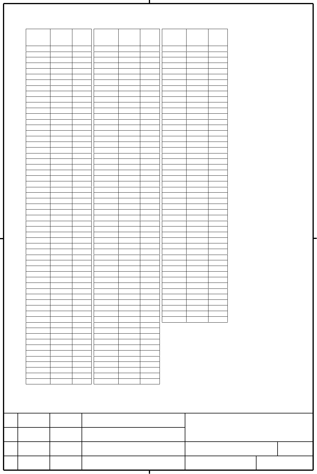
- Page 20Appendix : Relationship between speed command specified by PMC and actual command actual learning Actual learning actual learning actual learning speed speed speed speed speed speed speed speed command period command period command period command period command command command command (min-1) (0.5ms
- Page 21actual actual actual actual speed learning speed learning speed learning speed learning speed speed speed speed command period command period command period command period command command command command (min-1) (0.5ms) (min-1) (0.5ms) (min-1) (0.5ms) (min-1) (0.5ms) (min-1) (min-1) (min-1) (min-1)
- Page 22actual actual actual speed learning speed learning speed learning speed speed speed command period command period command period command command command (min-1) (0.5ms) (min-1) (0.5ms) (min-1) (0.5ms) (min-1) (min-1) (min-1) 639~641 638.30 188 938~944 937.50 128 1765~1791 1764.71 68 642~645 641.71 1