Spindle Learning Control Manual Additional Manual Page 4
Additional Manual
4/22
Design.
DateEd.
2002.05.06
SHEET
DRAW. No.
CUST.
TITLE
M.Niwa
Newly preparation
Spindle Learning Control Description
A-53866E-0425
FANUC LTD
01
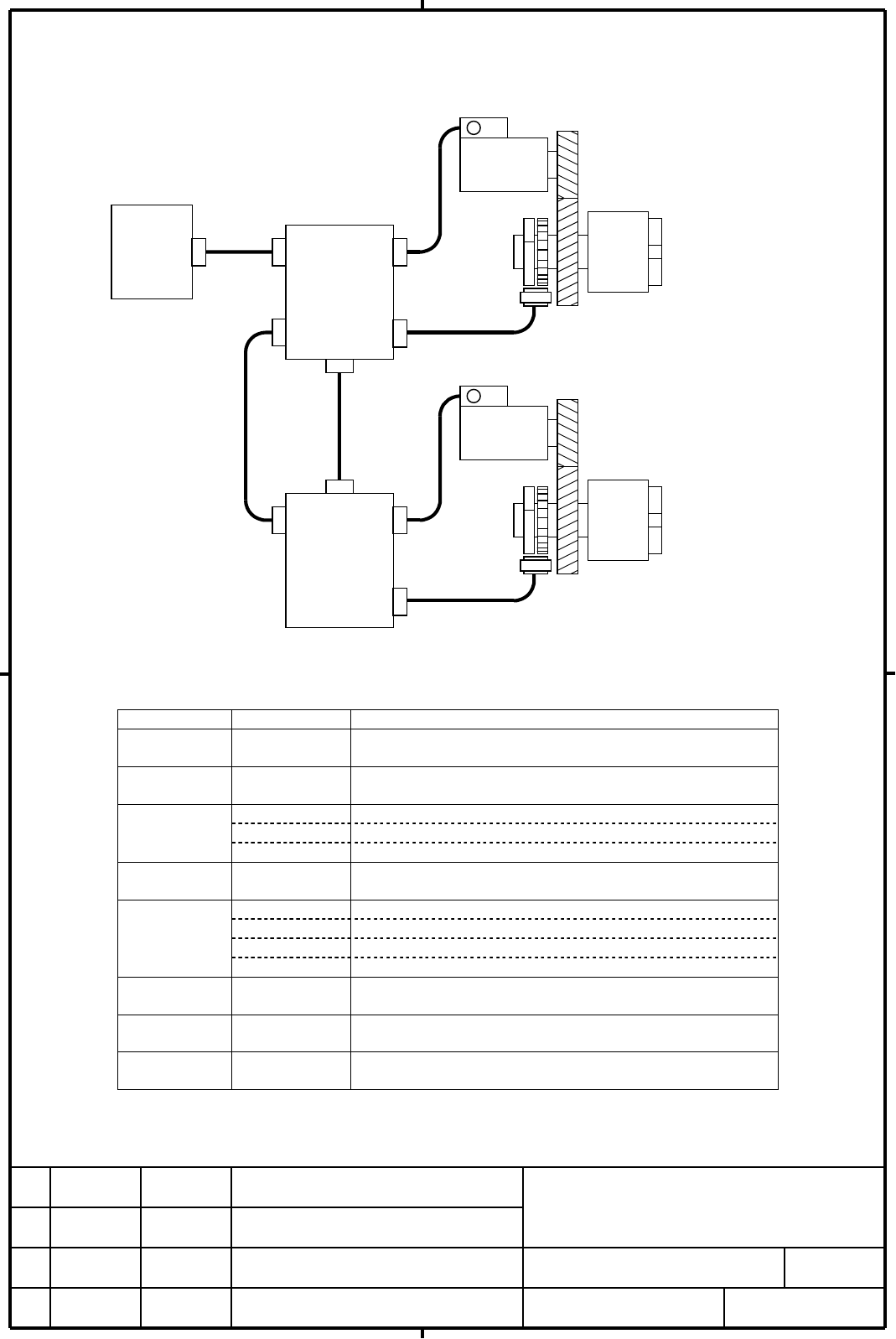
2.1.3. Example 2 : in case of full-closed system with gear reduction
JA7A
velocit
y
sensor
JYA2
SPM
TYPE B
JA7B
JX4
JYA2
SPM
TYPE B
JA7B
JX4
JYA4
JYA4
external
position
sensor
Spindle
motor
Spindle
shaft
1st spindle
(master axis)
2nd spindle
(slave axis)
velocit
y
sensor
external
position
sensor
Spindle
motor
Spindle
shaft
communication
between SPMs
CNC
Series
16i/160i/160is
18i/180i/180is
MODEL B
parameter settings related to sensors
parameter settings description
4000#0 depends on the
configuration
rotation directions of the spindle and motor
4001#4 depends on the
configuration
mounting direction of spindle sensor.
4002#3,2,1,0 0,0,1,0 BZi sensor
1,1,0,1 3rd party sensor (MZi / BZi sensor compatible reference signal)
1,1,1,0 3rd party sensor (driver type reference signal)
4003#7,6,5,4
or 4361
depends on the
sensor type.
sets the number of spindle sensor(external position sensor) gear
teeth.
4010#2,1,0 0,0,0 Mi sensor
0,0,1 MZi sensor
1,0,1 3rd party sensor (MZi / BZi sensor compatible reference signal)
1,1,1 3rd party sensor (driver type reference signal)
4011#2,1,0
or 4334
depends on the
sensor type.
sets the number of motor sensor gear teeth.
4056~4059 depends on the
configuration
sets gear ratio between the spindle shaft and motor shaft
4386* depends on
sensor type.
sets the number of spindle sensor (external position sensor) gear
teeth of master axis
* This parameter is valid only for slave axis (2nd spindle).
Contents Summary of Spindle Learning Control Manual Additional Manual
- Page 1FANUC AC SPINDLE MOTOR αi series Spindle Learning Control Description 1. General ................................................................................................................................................. 2 1.1. Overview..........................................................
- Page 21. General 1.1. Overview This manual describes methods for applying Spindle Learning Control for reducing periodic synchronous error between master and slave axes in gear cutting process. See “90A3 / 90A7 / 90B3 / 90B7 Learning Control Operator’s Manual : A-63696E-070” for detailed explanation of Le
- Page 32.1.2. Example 1 : in case of direct drive system velocity and position sensor Built-in spindle motor CNC 1st spindle (master axis) Series 16i/160i/160is JA7B JYA2 18i/180i/180is MODEL B SPM TYPE B JA7A JX4 velocity and position sensor communication between SPMs Built-in spindle motor JX4 JA7B JYA2
- Page 42.1.3. Example 2 : in case of full-closed system with gear reduction velocity sensor Spindle motor CNC 1st spindle (master axis) Series 16i/160i/160is Spindle JA7B JYA2 18i/180i/180is shaft MODEL B SPM external TYPE B position sensor JA7A JYA4 JX4 velocity sensor communication between SPMs Spindle m
- Page 52.1.4. Example 3 : In case of semi-closed system with gear reduction velocity and position sensor Spindle motor CNC 1st spindle (master axis) Series 16i/160i/160is Spindle JA7B JYA2 18i/180i/180is external shaft MODEL B SPM one-rotation TYPE B signal (proximity switch) JA7A JYA3 JX4 velocity and pos
- Page 62.2. Software configuration 2.2.1. Spindle software Software series / edition note Series 9D50 edition E(05) or later for induction motor control Series 9D53 edition B(02) or later for synchronous motor control 2.2.2. CNC software Software series / edition note Series B0H1 edition R(18) or later for
- Page 73. Block diagram CNC 2nd Spindle position feedback velocity feedback - - Slave Helical + + position + velocity spindle movement controller controller & command ( Gain Kp2 ) + + + Sensor No.4069~4072 Learning Learning period controller Feedforward (coefficient α2) No.4036 K2 Synchronous ratio K1 No.4
- Page 84. Input / Output Signals (CNC ↔ PMC) 4.1. Input signal (PMC → CNC) address #7 #6 #5 #4 #3 #2 #1 #0 G073 LCMODA G077 LCMODB LCMODA : Learning Control request signal (for 1st spindle) LCMODB : Learning Control request signal (for 2nd spindle) 0 : Disables Learning Control 1 : Enables Learning Control
- Page 95. Example of sequence master : 1st spindle, master axis of Spindle EGB control master axis speed command slave : 2nd spindle, slave axis of Spindle EGB control slave axis speed command synchoronization synchoronization start by G81 finish by G80 SYNMOD (F65#6) LCVARA (F48#5) LCMODA (G73#6) LCMODB (
- Page 106. Parameters 6.1. Parameters related to sensors *See “FANUC AC SPINDLE MOTOR αi series PARAMETER MANUAL : B-65280EN” for more information about sensor settings. Parameter No. 4000 ROTA1 #7 #6 #5 #4 #3 #2 #1 #0 ROTA1 : Relationship between the rotation direction of spindle and spindle motor. Paramet
- Page 11Parameter No. 4056 Gear ratio (HIGH) CTH1A=0, CTH2A=0 4057 Gear ratio (MEDIUM HIGH) CTH1A=0, CTH2A=1 4058 Gear ratio (MEDIUM LOW) CTH1A=1, CTH2A=0 4059 Gear ratio (LOW) CTH1A=1, CTH2A=1 data unit : Motor rotation for one rotation of spindle × 100 (In case of No.4006#1=1, motor rotation × 1000) data
- Page 126.2. Parameters related to position loop control for constant velocity command in PMC axis control *Master axis (1st spindle) must be driven by this function in Cs contouring mode when Spindle Learning Control function is used. *See “FANUC Series 16i / 18i SPECIFICATIONS FOR POSITION LOOP CONTROL FO
- Page 136.3. Parameters related to Spindle EGB control function *See “FANUC Series 16i / 18i -MA Spindle electronic gear box Specifications : A-77833E” for more information about Spindle EGB Control. *CNC software option is required to use Spindle EGB Control function 6.3.1. Parameters related to serial spi
- Page 14Parameter No. 4386 Gear teeth number of spindle sensor of master axis data unit : 1λ / rev data range : 0, 64 ~ 4096 This data is used to set the gear teeth number of spindle sensor of master axis. When this parameter is set to “0”, synchronous ratio “0” is assumed. *This parameter is valid only for
- Page 156.3.2. Parameters related to synchronous control Parameter No. 7700 HDR HBR #7 #6 #5 #4 #3 #2 #1 #0 HDR : Setting of the synchronization cancellation by reset HBR : Setting of the direction for helical gear compensation Parameter No. 7703 LFS #7 #6 #5 #4 #3 #2 #1 #0 LFS : Setting of the position com
- Page 166.4. Parameters related to Spindle Learning Control Parameter No. 4015 LRNFNC #7 #6 #5 #4 #3 #2 #1 #0 LRNFNC : Function bit of Learning Control 0 : Learning Control is invalid 1 : Learning Control is valid *CNC software option is required to use this function. This bit is automatically set by CNC so
- Page 17Parameter No. 4431 Duration of learning : LCTIME data unit : 0.1sec data range : 0 ~ 32767 This data is used to set duration of Learning Control. Learning controller stops update of compensation data after the expiration of the time interval that this parameter specifies (See following figure). If “
- Page 187. Diagnosis related to Spindle EGB Control Address Description Unit 716 Synchronous error between master and slave axis in Spindle pulse EGB Control (weight of error is slave axis side) *Both αi SPM TYPE B and i series model B CNC are required for the display of synchronous error on CNC diagnosis s
- Page 199. Tuning of Learning Controller Normally, only tuning of maximum and minimum order of dynamic characteristic compensation Gx (No.4427, 4428) is required. 9.1. Procedure of Leaning Controller tuning Step A Before tuning of Leaning Controller, tune current loop (in case of 3rd party spindle motor), v
- Page 20Appendix : Relationship between speed command specified by PMC and actual command actual learning Actual learning actual learning actual learning speed speed speed speed speed speed speed speed command period command period command period command period command command command command (min-1) (0.5ms
- Page 21actual actual actual actual speed learning speed learning speed learning speed learning speed speed speed speed command period command period command period command period command command command command (min-1) (0.5ms) (min-1) (0.5ms) (min-1) (0.5ms) (min-1) (0.5ms) (min-1) (min-1) (min-1) (min-1)
- Page 22actual actual actual speed learning speed learning speed learning speed speed speed command period command period command period command command command (min-1) (0.5ms) (min-1) (0.5ms) (min-1) (0.5ms) (min-1) (min-1) (min-1) 639~641 638.30 188 938~944 937.50 128 1765~1791 1764.71 68 642~645 641.71 1