FANUC PANEL i Additional Manual Page 16
Additional Manual
Connecting Manual
For FANUC PANEL i
EDIT
DRAW. NO. CUST
TITLE
DESCRIPTION
DESIG.
DATE
A
-83125E
16
/
SHEET
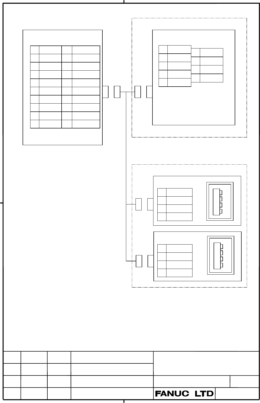
4.4 Serial Port 2
PANEL i
ex.) Host Computer
JD46
(PCR-EV20MDT) (Dsub 9 pin)
1 RD 11 SD
2 0V 12 USB1_0V
3 DR 13 ER
4 0V 14 USB2_0V
5 CS 15 RS
6 USB1+ 16 USB2+
7 CD 17 USB2-
8 USB1- 18 USB2_5V
9 RI 19 (+24V)
10 (+24V) 20 USB1_5V
( ) : Used with FANUC
I/O device.
1 CD
2 RD
3 SD
4 ER
5 SG
6 DR
7 RS
8 CS
9 RI
Note 1) The figure shows a sample host
computer interface and USB.
Design the cable to suit the
interface of the actual device to be
connected.
Note 2) The +24V pins of the interface for
PANEL i shown above can be
used only with the FANUC I/O
unit. Do not use these pins for
other purposes. Also, do not
attempt to simultaneously
connect two or more FANUC I/O
units to one PANEL i.
Note 3) Commercial USB devices cannot
be guaranteed its proper work
with PANEL i. Careful checkin
g
by the customer will be required.
And please be aware that those
devices in the market are not
almost considered about
waterproof and dustproof.
Note 4) Signals for USB 1 and 2 are
short-circuited with signals for
USB 1 and 2 in Chap. 4.10. When
one of these connector is used, the
other connector cannot be used.
4
3
2
1
4
3
2
1
ex.) Punch panel for USB port
USB port 1
1 USB1_5V
2 USB1-
3 USB1+
4 USB1_0V
USB port 2
1 USB2_5V
2 USB2-
3 USB2+
4 USB2_0V
(3)
Contents Summary of FANUC PANEL i Additional Manual
- Page 1FANUC PANEL i (5) CONNECTING MANUAL INTRODUCTION This manual describes mounting information of the FANUC PANEL i with Celeron 733MHz / Pentium III 866MHz / Pentium III 1.26GHz with the FANUC CNC to the machine tools. ATTENTION - The copyright of Windows R 2000, Windows R XP and other software provid
- Page 2INDEX 1. Total Connection -------------------------------------------------------------------------- 3 2. Specifications 2.1 Hardware specifications -------------------------------------------------------------------- 5 2.2 Environment ----------------------------------------------------------------
- Page 3: Optical Link Module & Cable 1. Total Connection : AMP(Dynamic) CNC Control Unit : AMP(mini-DIN6 pins) Master Board for 300i HSSB(COP21) : HONDA TSUSHIN(PCR 20 pins) or : HIROSE DENKI(Flat Cable34 pins) (5) HSSB Interface Board for 150i/160i/180i/210i : HIROSE DENKI(Flat Cable 40 pins) HSSB(COP7) :
- Page 4(Note 1) There are peripheral devices in the market which isn't suitable for installing in the machine tool and for using during the machine operation in the durability to the environment side. Confirm the instruction manual of the used peripheral well. (Note 2) Serial port 1 is not available in cas
- Page 52. Specifications 2.1 Hardware specifications Item Specification PC Unit (Basic Unit) Pentium III 1.26GHz or CPU Pentium III 866MHz or Celeron 733MHz Memory 512MB, 256M or 128MB Display for 150i 15.0” color TFT LCD (1024x768dots, 16M colors ) or Note) (3) Unit /160i 12.1” color TFT LCD (800x600dots,
- Page 6Hardware specifications (continuation) Hard Disk Drive Unit Hard Disk Drive 3.5” Hard Disk Drive 40GB or more over Ultra ATA/100 Weight 1.2kg Floppy Disk Drive 3.5-inch type Weight 0.4kg Note) It is necessary to change setting of plug on the master P.C.B. in (3) PANEL i when current FDD is used with
- Page 72.2. Environment When the PANEL i is used, the following environmental conditions (as measured top of the unit inside the cabinet) must be ensured for the unit. Ambient temperature Operating : +5~ +45°C Non-operating : - 20~ +60°C Change in temperature Up to 20 degrees/hour Ambient relative humidity
- Page 82.3. Power Specification 1) Power Supply Requirement A) Specification When the PANEL i is used, following power supply is required. Input Voltage DC +24V ± 10% Current capacity 10A or more over Note: If Handy File or other unit made by FANUC is connected to RS232C port, this value will increase by +
- Page 92.4. Shutdown operation Be sure to finish the OS and the applications through the proper operation of shutdown before turning the power off. Without the above-mentioned operation, there is no assurance of the following action. At worst, the command of initializing the HDD will not work. TITLE Connec
- Page 103. Mounting Space 3.1 PANEL i The following three spaces are required around the PANEL i. A: Space for connecting cables. B: If PCI extension board exists, this space B is required for cable connection. The dimension X depends on cables connected to the PCI Extension board. C: This space is required
- Page 112) Basic Unit 12.1” LCD Type 125 0 C C PCI 拡張 ボード X 40 40 A B A B Note) • Cable connecting area is necessary under this unit. 3) Basic Unit 15.0” LCD Type 125 C C PCI 拡張 ボード X A A B B Note) • Cable connecting area is necessary under this unit. TITLE Connecting Manual For FANUC PANEL i DRAW. NO. CUST
- Page 12.3.2. HDD Unit The HDD unit is mounted on the backside of the MDI or the FA Full-Keyboard. FA Full Keyboard FAN HDD Unit or MDI Unit 60 (5) C C 30 20 Refer to APPENDIX about outline dimensions of the HDD unit. Unit: mm Reserve space C in the above figure. And reserve space for connecting cables of H
- Page 134. Connection to Peripheral 4.1 Connector Location CA78B View from the back side CA78A Power Supply PCB Master PCB PCI Back Panel PCB CD34 COP7 (for 150i/160i/180i/210i) CA81A COP21 (for 300i) CPD14 CPD11A (5) CPD11B CPD11C CPE11C CD41L CD41M JD33 JD9 CD32L CA81B CD38U JD46 JA61 JA63 CD32U (5) Maste
- Page 144.2 Main Power Input PANEL i CPD14 A1 +24V B1 +24V A2 0V B2 0V A3 B3 AMP 2-178127-6 (CASE) 1-175218-5 (CONTACT, single) or 1-175196-5 (CONTACT, connection) 1) Cable Wiring A1 +24V ● +24V (5) A2 0V ● 0V B1 +24V B2 0V 2) Recommended Cable Material Use wire of AWG#16 (1.3mm2)or thicker. Note 1) Please
- Page 154.3 Serial Port 1 PANEL i ex.) Host Computer JD33 (PCR-EV20MDT) (DBM-25) 1 RD 11 SD 1 FG 14 2 0V 12 0V 2 SD 15 3 DR 13 ER 3 RD 16 4 0V 14 0V 4 RS 17 5 CS 15 RS 5 CS 18 6 (Reserve) 16 (Reserve) 6 DR 19 7 CD 17 (Reserve) 7 SG 20 ER 8 (Reserve) 18 (Reserve) 8 CD 21 9 RI 19 (+24V) 9 22 RI 10 (+24V) 20 (
- Page 164.4 Serial Port 2 (3) PANEL i ex.) Host Computer JD46 (PCR-EV20MDT) (Dsub 9 pin) 1 RD 11 SD 1 CD 6 DR 2 0V 12 USB1_0V 2 RD 7 RS 3 DR 13 ER 3 SD 8 CS 4 0V 14 USB2_0V 4 ER 9 RI 5 CS 15 RS 5 SG 6 USB1+ 16 USB2+ 7 CD 17 USB2- 8 USB1- 18 USB2_5V 9 RI 19 (+24V) 10 (+24V) 20 USB1_5V ( ) : Used with FANUC I
- Page 171) RECOMMENDED CABLE MATERIAL For RS232-C : A66L-0001-0284#10P・・・0.08mm2 10 pairs For USB : Please use special wire for USB (3) 2) RECOMMENDED PUNCH PANEL For RS232-C : A02B-0236-C191 (1m), A02B-0236-C192 (2m), A02B-0236-C193 (5m) The other punch panel (A02B-0120-C191 – C193) for CNC cannot be used
- Page 184.5 Parallel Port PANEL i ex.) Printer JD9 (PCR-EV20MDT) 1 *STB 19 0V 1 STD0 11 *STB 2 STD0 20 0V 2 STD1 12 0V 3 STD1 21 0V 3 STD2 13 *AFD 4 STD2 22 0V 4 STD3 14 0V 5 STD3 23 0V 5 STD4 15 *INIT 6 STD4 24 0V 6 STD5 16 0V 7 STD5 25 0V 7 STD6 17 *SLIN 8 STD6 26 0V 8 STD7 18 *ACK 9 STD7 27 0V 9 PE 19 *E
- Page 194.6 High Speed Serial Bus (HSSB) HSSB Interface Board PANEL i ( CNC side) Optical Fiber Cable COP 7 (for 150i/160i/180i/210i) COP7 (for 150i/160i/180i/210i) (5) COP21 (for 300i) COP21 (for 300i) 1) RECOMMENDED CABLE(Optical Fiber Cable) A66L-6001-0026#L1R003・・・Cable Length = 1 m A66L-6001-0026#L3R00
- Page 204.7 Keyboard, Mouse PANEL i Full Keyboard (in the market) CD32L (mini-DIN6) 6 5 KEYCLK 4 +5V 3 0V KB 2 1 KEYDATA FA Full Keyboard Mouse (in the market) CL32U (mini-DIN6) 6 5 MSCLK MS 4 +5V 3 0V 2 1 MSDATA Mouse (in the market) Note 1) Some kinds of Keyboard and Mouse may not work properly with the P
- Page 214.8. Hard Disk Drive 1) Cable Connection Connect HDD Signal cable to CA81A. Connect HDD Power cable to CPD11B. Connect FAN cable to CPE11C. Each cables are connected to HDD unit at exfactory. 2) Cable Length HDD Power Cable: 40cm HDD Signal Cable: 30cm HDD FAN Cable: 65cm Master board For the PANEL
- Page 224.9. Floppy Disk Drive 1) Recommended Floppy Disk Drive Floppy Disk Drive with no plate : A08B-0084-K001 (3) Panel mount type Floppy Disk Drive : A02B-0207-C009 When former FDD unit is used, the short terminal on the master board should be removed. (TM1 open) CD34(FDD) TM1 CA81A(HDD) CA81B(HDD2) 2)
- Page 234.10 USB PANEL i USB port1 (rear side) CD41L 1 USB1_5V 2 USB1- 3 USB1+ 1234 4 USB1_0V USB port2 (rear side) CD41M 1 USB2_5V 2 USB2- 3 USB2+ 1234 4 USB2_0V (5) USB port3 (front side, only for 300i) CD46L 1 USB3_5V 2 USB3- 3 USB3+ 1234 4 USB3_0V Note 1) Commercial USB devices cannot be guaranteed its
- Page 244.11 Ethernet Before attaching or removing cables, power off the PANEL i, and confirm that the power is off. When installing network cables, exercise sufficient caution so that the network will not be affected by any noise source. Some of the units (hub, transceiver, etc.) required to build a networ
- Page 254.12 Video Port PANEL i (Ex.) Monitor JA63 (PCR-EV20MDT) (Dsub 15 pin) 1 RED 11 (PU_1) 6 0V 1 RED 11 (SENCE) (3) 2 0V 12 VS 7 0V 2 GREEN 12 (DDA) 3 GREEN 13 0V 8 0V 3 BLUE 13 HS 4 0V 14 0V 9 (+5V) 4 (PU_1) 14 VS 5 BLUE 15 (+5V) 10 0V 5 0V 15 (DCK) 6 0V 16 0V 7 0V 17 (+5V) 8 (DDA) 18 HS 9 0V 19 (SENC
- Page 264.13 MDI for 300i (5) PANEL i MDI JA61 CK1 (PCR-EV20MDT) (PCR-E20MDK-SL-A) 1 *KEY00 11 *KEY01 1 *KEY00 11 *KEY01 2 *KEY02 12 *KEY03 2 *KEY02 12 *KEY03 3 *KEY04 13 *KEY05 3 *KEY04 13 *KEY05 4 *KEY06 14 *KEY07 4 *KEY06 14 *KEY07 5 *COM00 15 *COM01 5 *COM00 15 *COM01 6 *COM02 16 *COM03 6 *COM02 16 *COM
- Page 275.Method of Mounting PCI Extension Board 5.1 Usable Board The size of usable board on the PANEL i is defined as below figure, and one or two boards can be mounting on the PANEL i. Parts height of back side : up to 3mm Fix by screw Parts height of front side : up to 13mm Up to 106.68mm Unit : mm Up t
- Page 286. Outline 6.1 Basic Unit 10.4” LCD Type for 150i/160i/180i/210i 125 2 Paint Masking 25 (Mounting side of this plate is unpainted in 8mm Upper View width from the edge ) 290 5 Side View 220 210 4-Φ4 5 5 280 70 X Front View 5 Cable connecting Cable 280 area connecting area for PCI cards Grounding 4-M
- Page 296.2 Basic Unit 12.1” LCD Type for 150i/160i/180i/210i 125 30 2 25 Paint Masking (Mounting side of this Upper View plate is unpainted in 8mm width from the edge ) 340 5 270 Side 280 View 6-Φ4 5 X 5 165 165 40 5 Front View Cable connecting Cable 165 165 area connecting area for PCI cards 6-M3 Groundin
- Page 306.3 Basic Unit 15.0” LCD Type for 150i/160i/180i/210i 125 2 35 Paint Masking Upper View (Mounting side of this plate is unpainted in 8mm width from the edge ) 400 5 155 320 Side View 155 8-Φ4 X 5 5 195 195 5 Cable connecting Cable Front View connecting area area 8-M3 for PCI cards 195 195 Grounding
- Page 316.4 Basic Unit 10.4” LCD Type for 300i (5) 125 13 Upper View Front View 290 Side View 220 X 288 Cable connecting 4-M3 280 area for PCI cards Cable connecting area Front View Grounding terminal M4 x 10mm 204 (HOLE) 274 210 218 14.2 14.2 Rear View(right-lower) Panel Cutting Weight: 3.5kg (Basic Unit i
- Page 326.5 Basic Unit 15.0” LCD Type for 300i (5) 125 13 Upper View 8-M4 stud 400 (Length 8mm) Side View 320 X Front View Cable connecting Cable connecting 8-φ5 195 195 area area for PCI cards 155 Grounding 301 terminal (HOLE) M4 x 10mm 381 310 318 21.3 155 21.3 Rear View(right-lower) 398 Weight: 5.7kg Pan
- Page 336.6 Hard disk drive unit A (for 150i/160i/180i/210i and 300i) (Unit : mm) (5) A08B-0084-H100 44.6 37.6 6 66 136 42 40 6 28 25 83 39 TITLE Connecting Manual For FANUC PANEL i DRAW. NO. CUST 05 PANEL i for 300i is added A-83125E SHEET EDIT DATE DESIG. DESCRIPTION 33/
- Page 346.7 Hard disk drive unit B, C ( for 300i ) (Unit : mm) (5) A08B-0084-H130 44.6 9.2 163 29 39.2 6 180 6 8.3 35.35 121.3 40 119.7 35.35 8.3 6 A08B-0084-H131 8 8 19.2 28.4 25.8 101.4 67 35.3 121.3 40 35.4 TITLE Connecting Manual For FANUC PANEL i DRAW. NO. CUST 05 PANEL i for 300i is added A-83125E SHE
- Page 356.8 Floppy disk drive (A08B-0084-K001) (5) (Unit : mm) TITLE Connecting Manual For FANUC PANEL i DRAW. NO. CUST A-83125E SHEET EDIT DATE DESIG. DESCRIPTION 35/
- Page 366.9 Floppy disk drive unit (A02B-0207-C009) (5) 5 4-φ3.6 J2 FDD 150 140 ACRYLIC 104 J1 WINDOW 145 5 70 5 5 80 (単位: mm) Front View Side View 4-M3 134 140 64 (HOLE) 70 Weight : 0.8kg Panel Cutting TITLE Connecting Manual For FANUC PANEL i DRAW. NO. CUST A-83125E SHEET EDIT DATE DESIG. DESCRIPTION 36/
- Page 37Appendix A : Punch panel for PANEL i 1. Summary FANUC PANEL i is provided with the interface connectors for PC function for example a serial port or a parallel port. But it is not easy to connect/disconnect cables to these connectors for customer or end user after PANEL i is integrated in the machin
- Page 384. Environmental Requirement This unit should be mounted to the hermetically sealed cabinet because the connectors on the rear side of this punch panel are not covered with plates. The front door of this unit should be closed when the machine tool are operated. Environmental requirement of this unit
- Page 395.2 Serial port2 + USB i) Signal connections PANEL i side Punch panel side JD46 (PCR- EV20MDT) JD46 (PCR-E20LMDG) 1 RD 11 SD 1 RD 11 SD 2 0V 12 USB1_0V 2 0V 12 USB1_0V 3 DR 13 ER 3 DR 13 ER 4 0V 14 USB2_0V 4 0V 14 USB2_0V 5 CS 15 RS 5 CS 15 RS 6 USB1+ 16 USB2+ 6 USB1+ 16 USB2+ 7 CD 17 USB2- 7 CD 17
- Page 405.3 Parallel port i) Signal connections PANEL i side Punch panel side JD9 (PCR- EV20MDT) CD43B (Dsub-25pin female) 1 STD0 11 *STB JAE 1 *STB 14 *AFD Connector: DB-25P 2 STD1 12 0V Housing: DB-C2-J9-S6 2 STD0 15 *ERROR 3 STD2 13 *AFD 3 STD1 16 *INIT 4 STD3 14 0V 4 STD2 17 *SLIN 5 STD4 15 *INIT 5 STD3
- Page 415.4 Keyboard / Mouse (For Stand alone type Punch panel) i) Signal connections PANEL i side CD32L (Mini DIN6pin) (Keyboard) Punch panel side 6 5 KBCLK 4 +5V 3 0V CD44 (LY20_08P) A1 MSDATA B1 KBDATA 2 1 KBDATA A2 +5V B2 0V A3 MSCLK B3 KBCLK CD32U (Mini DIN6pin) (Mouse) A4 B4 6 5 MSCLK 4 +5V 3 0V JAE 2
- Page 426. Connection to peripheral 6.1 Connector location Punch panel (stand alone type) USB x 2 Serial port 2 Parallel port Mouse Keyboard FA Full keyboard with punch panel (15”LCD type) USB x 2 Serial port 2 Parallel port 6.2 USB port CD41 (USB×2) 1 5 USB device 2 6 1 USB1_5V 5 USB2_5V in the market 3 7
- Page 436.4 Parallel port CD42 (D-sub9pin Male) 14 *AFD 1 *STROBE 15 *ERROR 2 Data 0 16 *INIT 3 Data 1 17 *SLCT IN 4 Data 2 18 0V 5 Data 3 19 0V 6 Data 4 Parallel port device 20 0V 7 Data 5 Printer etc. 21 0V 8 Data 6 22 0V 9 Data 7 23 0V 10 *ACK 24 0V 11 BUSY 25 0V 12 PE 13 SLCT 6.5 Keyboard / Mouse (For S
- Page 447. Outline Dimensions 7.1 Punch panel (stand alone type) 38 Upper View 5 220 210 200 210 204 64 (HOLE) for cable 5 connector 5 5 70 70 2 70 70 4-φ4 4-M3 80 Panel Cutting Front View Side View Unit [mm] TITLE Connecting Manual For FANUC PANEL i DRAW. NO. CUST 04 This page is added A-83125E SHEET EDIT
- Page 457.2 FA Full keyboard with punch panel (15”LCD type) 20 38 Upper View 5 220 210 200 6-φ4 for cable 5 connector 5 390 5 2 70 70 400 Front View Side View Unit [mm] 210 204 (HOLE) 384 6-M3 195 195 390 Panel Cutting TITLE Connecting Manual For FANUC PANEL i DRAW. NO. CUST 04 This page is added A-83125E S
- Page 46Appendix B : Key codes of the soft-keys The key codes that are got when the Soft-key is pressed at the PANEL i are listed as follows. As for the other key codes from MDI keyboard part, refer to each corresponding MDI key definition file that are located on the folder “MDI¥Common” of Open CNC Drivers
- Page 47Revisions Revision Pages Contents of modifications 03 4 ・ Number of color is changed ・ PCI specification number is changed ・ Note for FDD is added ・ Applicable OS is added 14 ・ USB signal is added 15 ・ Mention about USB port is added (Cable, Punch Panel, Cable for Punch Panel) 20 ・ Specification num