AC SPINDLE MOTOR Built-in Descriptions Page 76
Descriptions
B-65202EN102
INSTRUCTION
4. SENSOR
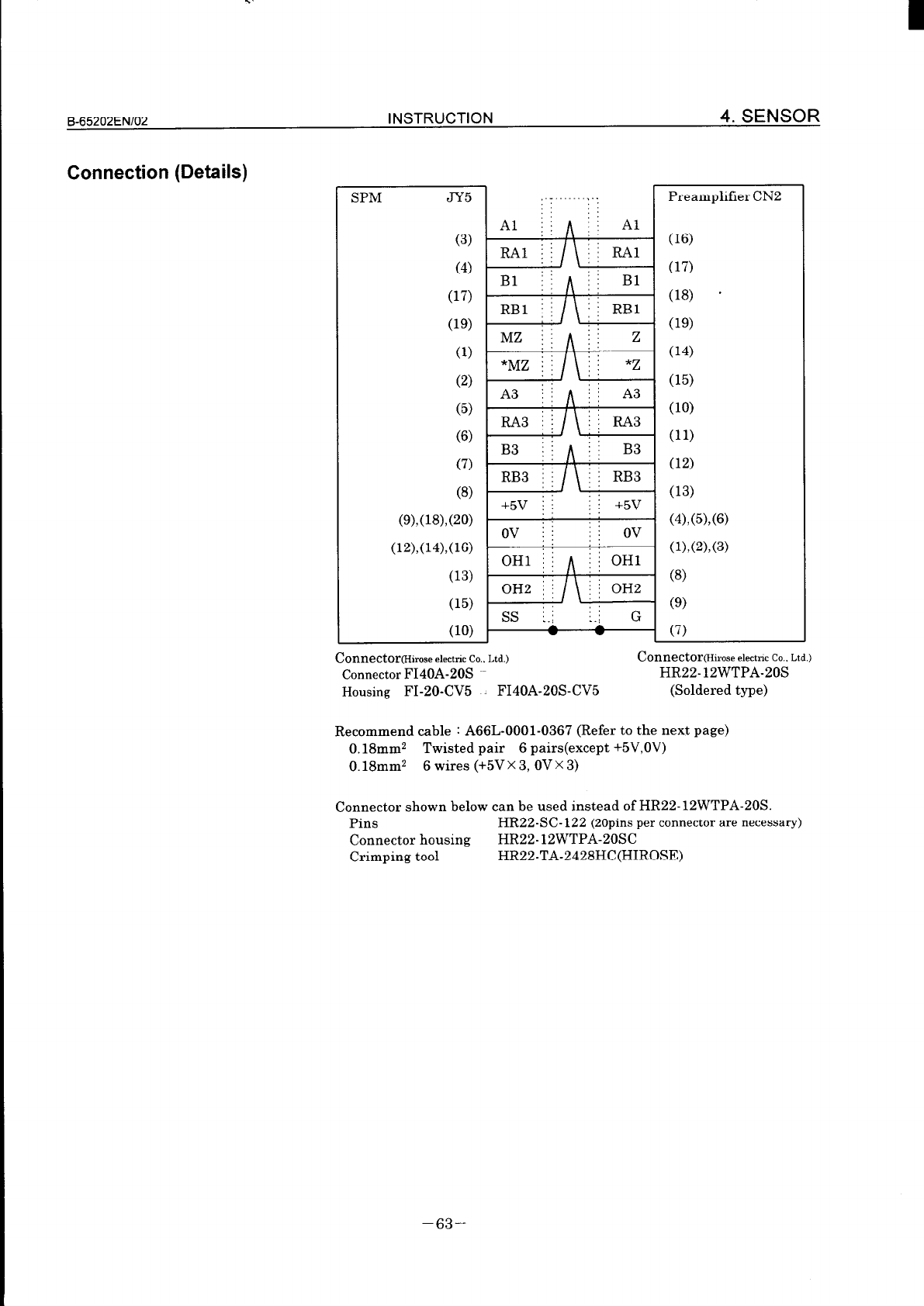
Connection (Details)
SPM JY5
Preamplifier CN2
(3)
(4)
(17)
(1%
(1)
(2)
(5)
(6)
(7)
(6)
(9).(16)?(20)
(12),(14),(16)
(13)
(15)
‘j BlI
: :
(16)
(17)
(16) *
09)
(14)
(15)
(10)
(11)
(12)
(13)
(4),(5),(6)
(l),(2),(3)
(6)
(9)
chUUXtOr(Hirose electtic Co., Ltd.)
Connector FI40A-20s
Housing FI-20-CV5 FI40A-20S-CV5
Connector(Hirose &&lc CO.. Ltd.)
HR22-12WTPA-20s
(Soldered type)
Recommend cable : A66L-0001-0367 (Refer to the next page)
0. 18mm2 Twisted pair 6 pairs(except +5V,OV)
0. 18mm2 6 wires (+5V X 3, OV X 3)
Connector shown below can be used instead of HR22-12WTPA-20s.
Pins
HR22-SC-122 (20pins per connector are necessary)
Connector housing
HR22-12WTPA-20SC
Crimping tool
HR22-TA_2428HC(HIROSE)
-63-
Contents Summary of AC SPINDLE MOTOR Built-in Descriptions
- Page 1GE Fanuc Automation Computer Numerical Control Products Alpha Series Built-in AC Spindle Motor Descriptions Manual B- 65202EN/02 March 1998�
- Page 2Warnings and notices for GFLE-003 this publication Warning In this manual we have tried as much as possible to describe all the various matters. However, we cannot describe all the matters which must not be done, or which cannot be done, because there are so many possibilities. Therefore, matters wh
- Page 3FANUC SERVO MOTOR series SAFETY PRECAUTIONS This “Safety Precautions” section describes the precautions which must be observed to ensure safety when using FANUC servo motors (including spindle motors). Users of any servo motor model are requested to read the “Safety Precautions” carefully before usi
- Page 4I SAFETY PRECAUTIONS 565202EN/02 1 DEFINITION OF WARNING, CAUTION, AND NOTE This manual includes safety precautions for protecting the user and preventing damage to the machine. Precautions are classified into Warning and Caution according to their bearing on safety. Also, supplementary information
- Page 5Ei-f35202EN/02 SAFETY PRECAUTIONS 2 WARNING ( WARNING 1 a Be safely dressed when handling a motor. Wear safety shoes or gloves when handling a motor as you may get hurt on any edge or protrusion on it or electric shocks. 0 Use a crane or lift to move a motor from one place to another. Motors are hea
- Page 6SAFETY PRECAUTIONS EJ--65202EN/02 1 WARNING 1 1 I 0 Connect power wires securely so that they will not get loose. A failure to observe this caution may cause a wire to be disconnected, resulting in a ground fault, short circuit, or electric shock. a Do not supply the power to the motor while any ter
- Page 7E%-65202EN/02 SAFETY PRECAUTIONS m CAUTION 0 FANUC motors are designed for use with machines. Do not use them for any other purpose. If a FANUC motor is used for an unintended purpose, it may cause an unexpected symptom or trouble. If you want to use a motor for an unintended purpose, previously con
- Page 8SAFETY PRECAUTIONS B-65202EN102 4 NOTE NOTE 0 Do not step or sit on a motor. If you step or sit on a motor, it may get deformed or broken. Do not put a motor on another unless they are in packages. 0 When storing a motor, put it in a dry (non-condensing) place at room temperature (0 to 40 “C). If a
- Page 9I B-65202EN/02 SAFETY PRECAUTIONS NOTE 0 Use a motor under an appropriate environmental condition. Using a motor in an adverse environment may cause a failure or trouble in it. Refer to this manual for details of the operating and environmental conditions for motors. 0 Do not apply a commercial powe
- Page 10SAFETY PRECAUTIONS 565202EN/02 MOTOR INSULATION RESISTANCE MEASUREMENT Measure an insulation resistance between each winding and motor frame using an insulation resistance meter (500 VDC). Judge the measurements according to the following table. I Insulation resistance Judgment 100 MC2 or higher I A
- Page 11B-65202EN102 INTRODUCTION INTRODUCTION This manual includes information of following models. FANUC BUILT-IN AC SPINDLE MOTOR a! series Standard type Single winding Double windings (Speed range switching control) a! B80M-1.5 (Y B112L-5.5 a B80L-1.1 (Y B112L-18.5 (Y BIOOS-2.2 cr B112LL-5.5 CYB1128-3.7
- Page 12CONSTRUCTION B-65202EN/02 CONSTRUCTION This manual consists of following three parts. I . SPECIFICATIONS Output characteristics, dimensions, cooling conditions, and so on are shown here. II. INSTRUCTION Installation instructions for the built-in motor are shown here. Refer to this part when you desi
- Page 13I B-65202ENI02 HANDLING OF BUILT-IN MOTOR HANDLING OF BUILT-IN MOTOR CAUTION You should read this clause before handling a built-in motor. If you handle the motor incorrectly, some trouble or accident will occur. The word “Motor” described here means stator, rotor, sensbr and all parts of the motor.
- Page 14B-65202EN102 Table of Contents Table of Contents SAFETY PRECAUTIONS ..................................................................... s-1 INTRODUCTION ............................................................................. P-l CONSTRUCTlON ..................................................
- Page 15Table of Contents B-65202EN102 4. SENSOR .............................................................................. 53 4.1 B,_,,LT_,,,,SENSOR ...................................................................... 53 4.1.1 Mounting .................................................................
- Page 16I I . SPECIFICATIONS�
- Page 17Eb65202EN102 SPECIFICATIONS INTRODUCTION CONSTRUNCTION OF THIS PART This part includes followings. 1. SPECIFICATIONS .......................................... 4 Technical data includes a cooling condition which is required to get rated output and to conform to the IEC standard. 1.1 STANDARD TYPE ..
- Page 181. SPECIFICATIONS SPECIFICATIONS B-65202ENI02 1 SPECIFICATIONS 11 . STANDARD TYPE tern Sl Continuous 1.5 1.1 2.2 3.7 5.5 (Max. current) (11) (20) (21) (25) (36) S2 Short time 2.2 3.7 3.7 5.5 7.5 *I Rated minutes 15min. 30min. 30min. 30min. 30min. Rated output (Max. current) kW (14) (26) (29) (33) (4
- Page 19B-65202EN/02 SPECIFICATIONS 1. SPECIFICATIONS (Y B112L-5.5 CYB112L-18.5 (Y B112LL-5.5 Model name 1233~B41C#lxxx 1233.B411#1xxx 1234~B41W1xxx Type No. *8 Low High Low High Low High lterr 5.5 5.5 18.5 5.5 5.5 Sl Continuous (39) (50) (AZ) (111) (52) (62) (Max. current) . 7.5 7.5 18.5 22 7.5 7.5 S2 Shor
- Page 20I 1. SPECIFICATIONS SPECIFICATIONS B-65202EN102 57 516 515 Coolant Flowing rate Ilmin 2 14.9 211.8 213.5 Specific heat JIg.K 1.78 Density g/cm3 0.87 Pressure kPa I2940 Capacity of cooler *I2 W 24900 L 2560 L 4900 Built-in sensor ‘4 TO11 Toll, TO14 TO11 Tl37 _. I __ I 47 I I I 17 , . I E)n+nr inortis
- Page 21B-65202EN/02 SPECIFICATIONS 1. SPECIFICATIONS 1251.B412#1xxx 1 .a7 1.78 J1g.K Specific heat 0.78 0.87 g/cm’ Density 52940 kPa Pressure *I 1 L 2900 22560 24900 W Capacity of cooler *I 2 TO18 TO11 Toll, TO18 Built-in sensor 4 High pulse coder l 27 38 38 Weight 16 16 22 0.060 0.085 0.086 1 Rotor inerti
- Page 22I 1. SPECIFICATIONS SPECIFICATIONS B-65202EN102 Model name cy B16OL-7.5 [Y B16OLL-25 (Y B180M-11 Type No. *f 1255.6411#Txxx 1256.B411#1xxx 1261.641C#lxxx tern Low 1 High Low 1 High Low 1 High 7.5 I 7.5 15 25 11 11 T (59) (64) (82) (120) (52) . (78) 11 11 22 30 15 15 30min. 30min. 10min. 30min. 20min
- Page 23I B-65202ENI02 SPECIFICATIONS 1. SPECIFICATIONS cy B180L-22 cr B18OLL-22 cr B225M-15 Model name 1262.B41UWxxx 1263.El411#1xxx 1273.8411#Txxx Tvpe No. l8 Low 1 High 1 I Low 1 High 1 Low 1 High .’ Item 18.5 1 22 1 18.5 1 22 15 15 I Sl Continuous (Max. current) . S2 Short time Rated minutes l1 (Max. cu
- Page 241. SPECIFICATIONS SPECIFICATIONS B65202EN/02 12 I HIGH-SPEED TYPE Model Name LY B8OS-5.5 (Y Bl OOS-11 (Y Bl OOS-11 LY BIOOL-1 l/25000 /40000 /30000 120000 Type No. l8 (Under develoPmenC 1228.B414#3xxx 1229-B902#1xxx 122%B415#lxxx em *Reactor *Reactor Low High Sl Continuous 5.5 (Max. current) (A:) (Z
- Page 25B-65202EN102 SPECIFICATIONS 1. SPECIFICATIONS (Y Bi 12M-15/20000 cr B112L-18.5/20000 (Y B112L-18.5/24000 Model name 1233.B814#1xxx (under moddlcaton) 1232.B415Mxxx 1233-B411#Txxx Type No. *8 Low 1 High Low 1 High Low 1 High hen 10 I 15 15 1 18.5 15 1 18.5 1 Sl Continuous 1 (83) (98) (80) (106) (83)
- Page 26I 1. SPECIFICATIONS SPECIFICATIONS B-65202EN102 Model name Type No. lE :em 1 Sl Continuous 1 kW (A) Power factor iated voltage of motor input *3 1 Vat Winding connection Number of poles qesistance of winding *IO 1 m R &5% Insulation class Temoerature rise of winding 1 K Required clearance Thermal sw
- Page 27I B-65202EN/02 SPECIFICATIONS 2. POWER CURVES 2 POWER CURVES STANDARD TYPE cy B80M-1.5 (A06B-1211 -Bl13#1 xxx) 31 2.2kW S2 15min. 1.5 1.1 0 3000 12000 15000 0 3000 12000 15000 Motor Speed (min.‘) Motor Speed (min.‘) a B80L-1 .I (A06B-1212-B413#1 xxx) 30I 51 4 3.7kW S2 30min. 3 2 1 4.4 0 1.3 0 1500 4
- Page 28I SPECIFICATIONS B-65202EN102 2. POWER CURVES a B112S3.7 (A06B-1231 -B413#lxxx) 7 6 5.5kW S2 30min.~ y 4 zi s 3 6 2 1 0 1 0 1500 4500 6000 0 1500 4500 6000 Motor Speed (min.‘) Motor Speed (min.‘) a! Bl12M-5.5 (A06B-1232-B412#1 xxx) I01 0 1500 6000 10000 Motor Speed (min.‘) Motor Speed (min.‘) Q! B11
- Page 29B-65202EN102 SPECIFICATIONS 2. POWER CURVES a Bl12L-18.5 (A06B-1233-B4 'Il#lxxx) n Low winding 200 25 1s3 2q% El 50 z a100 s b I- 50 0 0 1060 1500 2500 3500 0 1060 1500 2500 3500 Motor Speed (min.‘) Motor Speed (min.‘) n High winding 60 0' I “0 5000 10000 14000 0 5000 10000 14 Motor Speed (min.‘) Mo
- Page 302. POWER CURVES SPECIFICATIONS B-65202EN102 a B112LL-18.5 (A06B-1234-B41 l#Txxx) n Lowwinding 25 250 , I 204Nm S3 25% 20 z Y 15 s g IO 11 0 7.5 5 ~26.2 0 -17.9 0 865 1200 2000 4000 0 865 1200 2000 4000 Motor Speed (min.‘) Motor Speed (min.‘) WHigh winding r-17.5 -14.7 0 3500 12000 0 3500 12000 Motor
- Page 31B-65202EN102 SPECIFICATIONS 2. POWER CURVES a B132L-22 (A06B-1241 -B61 O#l xxx) n Low winding 0 750 900 1800 3000 Motor Speed (min.‘) Motor Speed (min.‘) WHigh winding 30 601 43.4Nm S2 30min. g 20 5 ,a 5 IO 0 I 5500 10000 12000 0 5500 10000 12000 Motor Speed (min.‘) Motor Speed (min.‘) cy B1608-5.5
- Page 32I 2. POWER CURVES SPECIFICATIONS B-65202EN102 a B160M-5.5 (A06B-1252-B412#lxxx) W Low winding 159Nm S2 20min. 7.5kW S2 20&n. 71.6 52.5 0 250 450 750 1000 0 250 450 750 1000 Motor Speed (min.‘) Motor Speed (min.‘) w High winding r-10.2 m7.5 0 1000 4000 7000 0 1000 4000 7000 Motor Speed (min.‘) Motor
- Page 33I B-65202EN/02 SPECIFICATIONS 2. POWER CURVES CYB160L-7.5 (A06B-1255-B41 l#Txxx) W Low winding 131 89.5 0 360 450 800 OO- 800 Motor Speed (min.‘) Motor Speed (min.‘) W High winding I51 11 kW S2 30min. 1 ,:::B”” 2 g 50 l- a;--,k 10.5 7.1 5.9 0 0 4.3 0 800 5000 10000 12000 0 800 5000 10000 12000 Motor
- Page 34, I 2. POWER CURVES SPECIFICATIONS B-65202EN/02 a! B180M-11 (A06B-126%B410#1xxx) WLowwinding 318Nm S2 20min. 0 0 300 450 800 0 300 450 800 Motor Speed (min.‘) Motor Speed (min-I) n High winding 2oI 4 15kW S2 20min. v- 5 11 kW Sl Cont. ‘j IO ~~ B 6 ~~__ ,.. ~23.8 0’ 0 x17.5 0 800 6000 0 800 6( 10 Mot
- Page 35I B-65202EN/02 SPECIFICATIONS 2. POWER CURVES a B18OLL-22 (A06B-1263-B41 l#lxxx) WLow winding 3o I 22kW S2 30min. g 600 18.5 t 15 !Jj 400 P c 200 n Motor Speed (min.‘) Motor Speed (min.‘) WHigh winding 30 25kW S2 30min. 26.2 -29.8 0 0 1300 8000 0 1300 8( 10 Motor Speed (min.‘) Motor Speed (min.‘) a!
- Page 36I 2. POWER CURVES SPECIFICATIONS B65202EN102 22 . HIGH-SPEED TYPE a B80S-5.5/40000 (Under development) IO p7.5 S2 IOmin. z: ‘i 5.5 2 4 0 Sl Cont. 2 0 0 0 20000 40000 0 20000 40000 Motor Speed (min.‘) Motor Speed (min.‘) a Bl OOS-1 l/30000 (A06B-1228-B414#3xxx) 20 3 - 15 Y IlkW Sl Cont. s IO ,a 6 5 0
- Page 37I B-65202EN102 SPECIFICATIONS 2. POWER CURVES a B100L-11/25000(A06B-1222-B415#1xxx) W Low winding 20 g I5 s IO a 15.9 s II.6 O 5 0 5500 9000 O- 0 9000 Motor Speed (min.‘) Motor Speed (min.‘) WHigh winding 5.7 4.2 0 9000 25000 0 9000 25000 Motor Speed (min.‘) Motor Speed (min.‘) Q! B112M-15/20000(A06
- Page 38I 2. POWER CURVES SPECIFICATIONS B-65202EN102 (Y B112L-18.5/20000 (A06B-1233-B41 l#Txxx) GLOW winding 117Nm S3 25% 35.8 26.2 0 1500 2500 4000 Motor Speed (min.‘) Motor Speed (min.‘) n High winding 301 22kW S2 15min. 15 11 -7.1 5.2 0 5000 10000 20000 Motor Speed (min.‘) Motor Speed (min.‘) a! B112L-1
- Page 39B-65202EN102 SPECIFICATIONS 2. POWER CURVES a B16OLL-22/15000 (A06B-1256-B61 I#1 xxx) n Low winding 22kW S2 IOmin. Motor Speed (min.‘) Motor Speed (min.‘) WHigh winding 30 g 20 5 $ 10 0: 0 8000 15000 0 8000 15000 Motor Speed (min-I) Motor Speed (min.‘) -25-
- Page 40I 3. DIMENSIONS SPECIFICATIONS B-65202EN/02 3 DIMENSIONS 31. STATOR L‘i ’ Wutlet L 42** Lo .h Upper view Side view(cut away) Unit : mm Modelname TypeNo.(AOGB) a B80M-1.5 1211-Bll3#lxxx a B8OL-1.1 1212-B413#1xxx (Y BIOOS-2.2 1221-B413#lxxx CY 81128-3.7 1231-B413#lxxx a B112M-5.5 1232-B412#lxxx a Bll2
- Page 41I B-65202EN/02 SPECIFICATIONS 3. DIMENSIONS I CY B112L-5.5 1233-B410#1xxx 60 70 25-30 25-30 3-5 3ormore 250rmore 800rmore cr B112L-18.5 1233-B411#1xxx 70 80 30-35 30-35 3-5 3 or more 30 or more 90 or more TY I _ ___ _ _ R11711-55 1234-B410#1xxx 70 80 30-35 30-35 3-5 3 or more 30 or more 90 or more I
- Page 42I 3. DIMENSIONS SPECIFICATIONS B-65202EN102 IryI[Y B112L-18.5 x a B112LL-5.5 Ia B112LL-18.5 I ---- - 11234-B410#1xxx II 234-B41 l#Txxx 14 14 6 6 6.5 6.5 MB MB Connection Connection C C 8 6 5.1 M6 Connection C 14mm’X 6,8mm* X 3 6.5. 5.1 MB Connection E 5.5 I 6 t 4.4 M6 Connection B NOTE WThe outer di
- Page 43B-65202EN/02 SPECIFICATIONS 3. DIMENSIONS 32. ROTOR NOTE Refer to the next page for Ef. I -29-�
- Page 443. DIMENSIONS SPECIFICATIONS B-65202EN/02 Reference size of spindle shaft I:& More than width “I” _ ._ ct B160LL-25 1256-B411#1xxx roo,o Efaom 101.4SEfd103 ct B180M-11 1261-B41O#lxxx Ef ZE 12 cv B180L-22 1262-B41O#lxxx Ef 2% 1255SEfS126 _ __ _ a B18OLL-22 1263-B411#1xxx Ef :Z,Y ____ 1214.4SEfSl25.0
- Page 45B-65202ENl02 SPECIFICATIONS 3. DIMENSIONS 33. SENSOR 3.3.7 Built-in Sensor (with Mounting Ring) Note Diameter of through hole for connector is 4 25mm. Accessories (Manufactured by Honda Tsushm Kqyo Co. Ltd.) Connector :Z-374, 2 pieces Contact :HKP-F413, 12 pieces Reference Crimping tool for HKP-F413
- Page 46I 3. DIMENSIONS SPECIFICATIONS B-65202EN102 Built-in Sensor (without Mounting Ring) cz Note * Diameter of through hole for connector is o 25mm. a Accessories (Manufactured by Honda Tsushin Kogyo Co. Ltd.) I Connector :Z-374, 2 pieces / I Contact :HKF’-F413, 12 pieces I 4x I 1I I jj Reference I L’ Cr
- Page 47B-65202EN102 SPECIFICATIONS 3. DIMENSIONS Detecting ring Detecting ring A Detecting ring B 7-f I Dimensions R’R_._._.-.-‘-.-i-.-‘-.-._ -.- & 8 - .m 8 n 8 Is cr 8 F Refer to the precede section “Built-in sensor” for details of detector and mounting ring. NOTE WPress fit the rings on a sleeve, then in
- Page 483. DIMENSIONS SPECIFICATIONS B-65202EN/02 3.3.2 High Resolution Magnetic Pulse Coder Signal cables 400mm agnetic drum mmimum R@O/ Refer to the next page for details of magnetic drums. NOTE Muse this sensor under 50°C. WPreamplifier is attached to this sensor. H Detectors, drum and preamplifier have
- Page 49I B-65202ENl02 SPECIFICATIONS 3. DIMENSIONS Magnetic Drum 2 10 /110.011 25*o. Refer to the previous page for details of detector. Allowable maximum speed -35-�
- Page 50I 3. DIMENSIONS SPECIFICATIONS B-65202EN102 Preamplifier NOTE W Use this preamplifier under 50°C. WThis preamplifier is necessary to use the high resolution magnetic pulse coder. n Detectors, drum and preamplifier have been adjusted before shipping and given the same serial number. Therefore do not
- Page 51B-65202ENl02 SPECIFICATIONS 3. DIMENSIONS 34. COOLING JACKET (REFERENCE) H E_ F _, Unit : mm 180 1 205 1 I 128 1 6 1 5.5 j -11.5 6 I 5.5 I 4 9 1 180 1 202 I 40 5 I 235 1 6 1 5 1 2 5 I 7.5 I 36 NOTE n Recommended material is FC iron. n These data do not include interference for the stator shrink fitt
- Page 52I 3. DIMENSIONS SPECIFICATIONS B-65202EN102 35. REACTOR It is necessary to connect the reactor between the motor and the amplifier (SPM) for a B80S5.5/40000 and for (t B lOOS- 1 l/30000. m Dimensions Unit : mm Specifications ,. [y 88os-c:wm A81L-0001-0141 0.1 3 130 cont. H 125orless 9 LT lWXXS-~i~ A
- Page 53II. INSTRUCTIO�
- Page 54I B-65202EN102 INSTRUCTION INTRODUCTION CONSTRUCTION OF THIS PART This partedited for the parson who design and assemble a spindle. Read this chapter before design and assemble the spindle. . 1. GENERAL.. ...... ...... ... ... ........... ........ ........ . . 42 1.1 NOTES...........................
- Page 55I 1. GENERAL INSTRUCTION B-65202EN102 1 GENERAL 11 . NOTES Liquid cooling FANUC’s built-in spindle motors are developed based on liquid cooling. You will not obtain the rated output by air cooling. Use liquid cooling system so that the rated output can be obtained. Recommended coolant : IS0 VG2 (e.g
- Page 56B-65202EN102 INSTRUCTION 1. GENERAL Check resistance and insulation Before and after assembling a spindle, check the resistance and insulation of winding. And also, check these on regular intervals. WARNING Shut down the power supply and disconnect the leads which are connected tc the amplifier befo
- Page 57I 1. GENERAL INSTRUCTION B-65202EN102 12 . PROTECTION CLASS (WATER AND DUST PROOF) Protection class of a spindle should be IP54 or more, and the part of drain should be IP44 or more. (Refer to the IEC34-5 standard for details of IP.) When appropriate protection is not maintained, contamination like
- Page 58B-65202EN102 INSTRUCTION 1. GENERAL 13 . CLEARANCE AND CREEPAGE (DISTANCE FOR INSULATION) Clearance fl Clearance between windings and other metallic materials has to be 3mm or more, and this condition has to be applied for all directions of windings. These are described in VDEOllO. Refer to VDEO 110
- Page 592. STATOR INSTRUCTION B-65202EN/02 2 STATOR 21. HEAT SHRINK FITTING n Stator outer diameter is machined within the proper tolerance. But it sometimes has distortion of O.lmm after winding procedure. Even if there is the distortion of O.lmm in the stator outer diameter, it is an allowable distortion
- Page 60, B-65202EN/02 INSTRUCTION 2. STATOR 22 . POWER LEADS CONNECTION n Connection A H Connection B n Connection C n connection D SPM 0 R - n Connection E USwitching of MCC for low speed winding : MCC l=ON MCCB=OFF for high speed winding : MCCl=OFF MCCB=ON NOTE n MCC(Switching unit) is not attached to th
- Page 61I 2. STATOR INSTRUCTION B-65202EN/02 23. CABLE CONNECTION (OUTLINE) Built-in sensor Power leads r - . 7 I I Switching unit MO.... -iv 1 1 Fee/dback cable Amplifier @PM) Shielded cable Over heat cable Connector or termmal box UP54 or more is recommended) High resolution magnetic pulse coder Amplifier
- Page 62B-65202ENl02 INSTRUCTION 2. STATOR 2.3.1 Reactor Connection Reactor must be connected between motor and amplifier for ct B80S- 5.5140000 and for o B lOOS- 1 l/30000. Amplifier Motor CAUTION n If the reactor is not used when it is necessary, it affect the motor life. Be sure to use the reactor when i
- Page 63I 3. ROTOR INSTRUCTION B-65202EN/02 3 ROTOR 31. MACHINING AND FINISHING Indicator Method When machining the inner diameter of the rotor, chuck the outer diameter of the core, as shown at right. As shown in the diagram, if the rotor is gripped by a divided jig, the chucking is more stable. Further, w
- Page 64B-65202ENl02 INSTRUCTION 3. ROTOR Steady rest Avoid using as steady rest. As the rotor has slots on its outer wall, the runout of the rotor increases if it is supported by a rest. Clearance When machining a rotor, avoid making a clearance as shown at right. The inner wall of the rotor must form a pe
- Page 653. ROTOR INSTRUCTION B65202EN102 33. HEAT SHRINK FITTING WHeat shrink fitting is recommended for mounting method of a rotor to a shaft. Use press machine when the interference is large. But in this case, avoid the deformation of the shaft and the rotor. WWhen mounting the rotor, the rotor has to be
- Page 66B-65202EN102 INSTRUCTION 4. SENSOR 4 SENSOR 41. BUILT-IN SENSOR 4.1.1 Mounting The built-in sensor has to be installed on the rotating axis at the side of power leads, and the ring A must face the motor. If the sensor is installed incorrectly, the motor cannot be controlled normally. Install ring A
- Page 67I 4. SENSOR INSTRUCTION B65202EN/02 4.1.2 Interference Detecting rings are expanded by centrifugal force when the spindle rotates. The interference for the detecting rings to the spindle or sleeve must be greater than expansion at the maximum spindle speed. The following table lists recommended inte
- Page 68B-65202ENl02 INSTRUCTION 4. SENSOR 4.1.3 Built-in Sensor Connection Connection diagram Built-in sensor , NOTE W Prepare the cable K17 by yourself. mover heat cable is connected to the motor. n Refer to the next page for details of the cable. n There is no problem that the cable K17 is connected on t
- Page 69I Connection (Details) r Built-in sensor : : : PA ~j A : j VA (5) (5) “PA j j ; j *VA (6) :: : : (2) PB :: : : VII3 : CNl m : : (6) . *PB ; j : : *w : (8) (3) *MZ ; i : ; “VZ (2) (1) MZ i j ; ~ VZ (1) (2) +5V j j ji +5V m(mcw (4),(l) CN2 *Note (16) (6)>(3) (5) 1 - 1nnectorcHirosed&~ic CO Ltd) Connec
- Page 70B-65202EN102 INSTRUCTION 4. SENSOR Cable K17 for built-in sensor connection (Reference) Cable for built-in sensor interface connection. Contact the manufacturer as required. -randed wire of tinned annealed copper (JISI Heat resistant, Oil resistant, Flame retardant ~~1 T mm 0.9 0.54 0.25 0.2 mm (Ave
- Page 71I 4. SENSOR INSTRUCTION B-65202EN102 4.1.4 Feedback Signal Adjustment Check the feedback signal after installing the sensor. Pins for checking are on the check board. The check board is not attached to the amplifier or to the motor. Refer to the Maintenance Manual (B-65165) of FANUC CONTROL MOTOR Q
- Page 72I B-65202ENI02 INSTRUCTION 4. SENSOR Speed and position feedback signal Measuring condition : Rotation : Clockwise, Counterclockwise Speed : 1500min-’ Pins : PAl, PBl (PAZ, PB2 for sub spindle) PA1 (PAZ) II PBI (PB2) Paint to be Target value Remarks checked Ampfitude of vs 0.66 - 0.93v Offriet of U,
- Page 734. SENSOR INSTRUCTION B-65202EN102 42. HIGH RESOLUTION MAGNETIC PULSE CODER 4.2.1 Mounting The high resolution magnetic pulse coder has to be installed on the rotating axis at the side of power leads. If the sensor is installed incorrectly, the motor cannot be controlled normally. Magnetic drum Dete
- Page 74B-65202EN102 INSTRUCTION 4. SENSOR Runout of outer surface of drum The runout of the outer surface of the magnetic drum must be 15 Q m or less Datum plane CAUTION Use indicator tip on the surface within 5mm from the ‘7” printed side. If the tip contact other surface of the drum, magnetic data on the
- Page 754. SENSOR INSTRUCTION B-65202EN102 4.2.3 High Resolution Magnetic Pulse Coder Connection Connection diagram High resolution Magnetic pulse coder I I Over heat cable NOTE WPrepare the cable K18 by yourself. mover heat cable is connected to the motor. Refer to following “Over heat cable connection” fo
- Page 76B-65202EN102 INSTRUCTION 4. SENSOR Connection (Details) SPM JY5 Preamplifier CN2 (3) (16) (4) (17) :‘j : BlI (17) (16) * (1% 09) (1) (14) (2) (15) (5) (10) (6) (11) (7) (12) (6) (13) (9).(16)?(20) (4),(5),(6) (12),(14),(16) (l),(2),(3) (13) (6) (15) (9) chUUXtOr(Hirose electtic Co., Ltd.) Connector(
- Page 774. SENSOR INSTRUCTION B-65202EN102 Pin assignment Connector JY5 Connector CN2 Over heat cable connection @ Remove the blind plate on the hole for a cable gland from the preamplifier box. Attach the cable gland on the plate for fix. Prepare the cable gland by yourself. Outer diameter of cable : 6 5.2
- Page 78B-65202ENI02 INSTRUCTION 4. SENSOR Cable K18 for high resolution magnetic pulse coder (Reference) Cable for high resolution magnetic pulse coder interface connection. Contact the manufacturer as required. lo-pair cable item 1 Unit Specifications Product No. I A66L-0001-0367 (FNC-019) Manufacturer Sh
- Page 794. SENSOR INSTRUCTION B-65202EN102 4.2.4 Feedback Signal Adjustment Check the feedback signal after installing the sensor. Pins for checking are on the check board and in the preamplifier. The check board is not attached to the amplifier or to the motor. Refer to the Maintenance Manual (B-65165E) of
- Page 80B-65202EN102 INSTRUCTION 4. SENSOR Speed and position feedback signal for motor Measuring condition : Rotation : Clockwise, Counterclockwise Speed : 500min-l or less Pins : PAZ, PB2 !!!I@- vs - VRM(2. W) b’o ov If the different value from the target shown below is measured, adjust the vs PB2 : ti3G
- Page 81I 4. SENSOR INSTRUCTION B-65202EN102 One rotation signal Measuring condition : Rotation Clockwise, Counterclockwise Speed 500min-’ or less Pin z If the different value from the target shown below is measured, adjust the Volume and pin assignment r :NO CNI CN2 Circuit board in the preamplifier -68-
- Page 82B-65202EN102 INSTRUCTION 4. SENSOR 43. SIGNAL CABLE LENGTH (ALLOWANCE) Calculate the allowable signal cable length between the sensor and the amplifier according to the formula below. L : Cable length [m] m : Number of wires connected to power supply and OV A V: Allowable voltage drop (See table) I
- Page 83I 5. LOAD METER (DYNAMOMETER) INSTRUCTION B-65202EN/02 5 LOAD METER (DYNAMOMETER) A load meter (dynamometer) indicates the load factor. The load factor is the ratio of average output to the maximum output of the spindle motor when the spindle of the machine tool operates with no load and during cutt
- Page 84B-65202EN102 INSTRUCTION 5. LOAD METER (DYNAMOMETER) 51. STANDARD TYPE a B80M-1.5 (A06B-1211 -B113#1 xxx) 6.1 ~-II 0 5.7 8.3 10 a B80L-1 .I (A06B-1212-B413#lxxx) :I a Bl OOS-2.2 (A06B-1221 -B413#lxxx) 0 2.5 8.3 10 a B1128-3.7 8ool0 (A06B-1231 -B413#1 xxx) I 5.0 8.3 10 :;‘I 0 5.6 8.3 10 I a B112M-5.5
- Page 85, 5. LOAD METER (DYNAMOMETER) INSTRUCTION B-65202EN/02 ct B112L-5.5 (A06B-1233-B41 O#lxxx) n Low speed winding 6.1 1600 0 0 48 6.5 83 10 n High speed winding 0 6.1 8.3 10 a B112L-18.5 (A06B-1233-B41 l#lxxx) H Low speed winding 0 4.8 5 WHigh speed winding 0 7.0 8.3 10 LYB112LL-5.5 (A06B-1234-B410#lxx
- Page 86B65202EN102 INSTRUCTION 5. LOAD METER (DYNAMOMETER) a B112LL-18.5 (A06B-1234-B41 l#Txxx) W Low speed winding 0 0 4.9 6 1 6.8 8.3 10 n High speed winding 12~~1 a B132L-5.5 (A06B-1241 -B41 O#l xxx) 0 7.0 8.3 10 H Low speed winding ‘:;I 0 61 83 10 n High speed winding 5.8 ~~~~ 0 6.1 8.3 10 a B132L-22 (
- Page 875. LOAD METER (DYNAMOMETER) INSTRUCTION B-65202EN102 cr B1608-5.5 (A06B-1251-B412#lxxx) a B16OM-5.5 (A06B-1252-B412#lxxx) n Low speed winding 0 6.1 8.3 10 W High speed winding 0 6.1 0.3 10 a B160M-11 (A06B-1252-B712#1 xxx) WLow speed winding ~~;I 0 4.5 8.3 10 n High speed winding 5.2 6.1 6000 388 22
- Page 88B-65202ENl02 INSTRUCTION 5. LOAD METER (DYNAMOMETER) a B16OL-7.5 (A06B-1255B41 l#Txxx) WLow speed winding 450 360 0 0 5.7 6.7 6.3 10 n High speed winding 0 5.7 63 10 a B16OLL-25 (A06B-1256-B41 I#1 xxx) H Low speed winding 6.1 3000 2000 1500 88 0 0 4.7 5 7 6.4 7 0 6.3 10 n High speed winding 0 7.0 6.
- Page 895. LOAD METER (DYNAMOMETER) INSTRUCTION B-65202EN102 a B18OL-22 (A06B-1262-B41 O#l xxx) H Low speed winding 800 500 350 0 0 50 5.8 7.0 6.3 10 W High speed winding a B18OLL-22 (A06B-1263-B411 #I xxx) WLow speed winding W High speed winding a! B225M-15 (A06B-1273-B41 :‘I l#Txxx) 0 7.3 83 10 WLow speed
- Page 90B-65202EN102 INSTRUCTION 5. LOAD METER (DYNAMOMETER) 52. HIGH-SPEED TYPE a B80S-5.5140000 (Under development) :rI 0 6.1 8.3 10 a Bl OOS-1 l/30000 (A06B-1228-B414##3xxx) a Bl OOS-1l/20000 (A06B-1229-B902#1 xxx) a Bl OOL-1l/25000 (A06B-1222-B415#1 xxx) WLow speed winding wall0 W High speed winding 8.1
- Page 915. LOAD METER (DYNAMOMETER) INSTRUCTION B-65202EN/02 a B112M-15/20000(A06B-1232-B415#1xxx) W Lowspeed winding _T L 0 5.6 0.3 IO n High speed winding *Ooo;~I 0 6.8 8.3 10 a B112L-18.5/20000(A06B-1233-8411#Txxx) n Low speed winding 6.1 6.8 4000 2500 18CKl 1500 0 0 5.6 6.9 8.3 10 n High speed winding (
- Page 92B-65202ENl02 INSTRUCTION 5. LOAD METER (DYNAMOMETER) a Bl6OLL-22/15000 (A06B-1256-861 I#1 xxx) WLow speed winding _1 0 5.7 8.3 10 W High speed winding -79-�
- Page 93APPENDI�
- Page 94B-65202EN/02 APPENDIX INTRODUCTION CONSTRUCTION OF APPENDIX Appendix includes many reference data and information. A_ ACCELERATION TIME.. ....... ... ................. .. . . . . a4 B_ COOLING CONDITION.. . ... ......... .. ... ... ... ..... . . . . 85 C. ROTOR SLEEVE (REFERENCE) . . . a. . . . . .
- Page 95A. ACCELERATION TIME APPENDIX B65202EN102 A ACCELERATION TIME In acceleration, the output of the built-in AC spindle motor is 120% of S2 or S3 rated output. The acceleration time required for acceleration can be calculated from the expressions below. As the load torque of the machine is not consider
- Page 96B-65202EN102 APPENDIX B. COOLING CONDITION B COOLING CONDITION IC code IC code means “International Cooling” and it indicates the cooling system for a motor standardized in IEC34-6. All FANUC’s built-in AC spindle motors are developed under IC9U7A7 and this means all motors require separated oil coo
- Page 97C. ROTOR SLEEVE (REFERENCE) APPENDIX B-65202EN102 C ROTOR SLEEVE (REFERENCE) Rotor sleeve (Stepped sleeve) Using a stepped sleeve in the inner diameter of rotor, the rotor can be separated from the shaft using the oil pressure (from 30MPa to 80MPa) in the stepped sleeve, and maintenance ability of r
- Page 98B-65202ENi02 APPENDIX C. ROTOR SLEEVE (REFERENCE) Dimensions (Reference) Unit : mm u “I”“u-I l,LY”“” CY BIOOL-II/25000 11222-B415#1xxx~ f%ta Bl12M-15/20000 11232-B415Wxxxi 73.5 1 59.1 1 61 58.9 20 6.6 or less 20 6 208 1233-B411#Txxx 589 20 6.6 or less 20 6 266 ““.” __ _._ _. .___ -- I --- 1 30 16.6
- Page 99C. ROTOR SLEEVE (REFERENCE) APPENDIX B-65202EN/02 NOTE n All data shown above are just for reference. n 4 N changes if the stopper is on the J side or if the L changes. Therefore change 4 N according to your spindle design. nTap of 0 is for the nozzle shown below. n Consider the oil oressure, from 3
- Page 100B-65202ENl02 APPENDIX D. SWITCHING UNIT D SWITCHING UNIT It is necessary to use the Switching Unit for the motor of speed range switching control. The switching unit is not attached to the motor. Therefore order according to the following order number, or prepare according to the specifications show
- Page 101E. PARAMETERS APPENDIX B-65202EN102 E PARAMETERS When setting automatically the parameters are set corresponding to the model code. When “None” is entered for the model codes corresponding to the models, the parameter data is mostly set automatically in agreement with the model codes. Change the sec
- Page 102B-65202ENl02 APPENDIX E. PARAMETERS E-1 STANDARD TYPE r Model code 101 102 120 Applicable ROM Version) (9DOO/G) (9DOO/G) (9DOO/O) Model name CY B80M cr B8OL cr BIOOS -1.5/15000 -1.1/8000 -2.218000 (L150) (L143) (L140) 1512.2 kW 1.1/3.7kW 2.213.7kW Parameter No. 3000/15000 1500/8000 1500/8000 FSO FS1
- Page 103E. PARAMETERS APPENDIX B-65202ENIO2 Model code 121 4pplicable ROM Version) (9DOO/O) ___ Model name a B112S a B112M Y B160S .3.7/6000 ~5.5/10000 5.5/6000 :L151) (L141) (L152) 3.715.5kW 5.517.5 kW j.5/7.5kW 1500/10000 iOO/6000 FSO min.’ min.’ miri’ 5507 3007 4007 10000000 10000000 10000000 9508 3008 4
- Page 104B-65202EN102 APPENDIX E. PARAMETERS cr B112L viodelcode 165 Model name -5.5112000 (Applicable ROM Version) (9DOOIO) (L510) for low speed winding forhigh speed winding 5517.5 kW 5.517.5kW Parameter No. Parameter No. 680/1600 1600/12000 FSO FS15 FS16 min.' FSO FS15 ~ll&iril 6507 3007 6508 3008 4008ool
- Page 105E. PARAMETERS APPENDIX B-65202ENI02 cy Model code 166 Model name -18.5/14000 (Applicable ROM Version) (9DOO/O) I II \-- 5111 .I I for low speed winding forhigh speed winding 15118.5kW 18.5/22kW Parameter No. Parameter No. 1500/3500 5000/14000 FSO 1 FS15 1 FS16 min.' FSO 1 FS15 1 FS16 min-'* I 6507 1
- Page 106B-65202EN/02 APPENDIX E. PARAMETERS r r c a Bll2LL I- _^- Modei code Itif Model name -5.5/12000 (ApplicableROM Version) (9D0010) (L512) L for low soeed winding wiriding 5.517.5kW 5 .5/7.5 kW Parameter No. Parameter No 4150/1000 rII300/12000 FSO FS15 FS16 min.' FSO FS15 FS16 min.' 6507 3007 4007 4008
- Page 107E. PARAMETERS APPENDIX B-65202ENI02 (Y B112LL Model name -18.5/12000 Model code 168 (Applicable ROM Version) (9D0010) (L513) for low speed winding forhigh speed winding 15l18.5kW 18.5122kW Parameter No. Parameter No. 1200/4000 3500/12000 FSO FS15 FS16 min.' FSO FS15 FS16 min.' * 6507 3007 4007 IOOOO
- Page 108B-65202ENI02 APPENDIX E. PARAMETERS I cy81321 ._L fviodeicode IbY Model name -5.5/12000 (Applicable ROM Version) (9DOO/O) (L514) for low speed winding forhigh speed winding 5.5175 kW 5.517.5kW Parameter No. Parameter No. 330/1500 1500/12000 FSO FS15 FS16 min.' FSO FS15 FS16 miri' 6507 3007 4007 lOOO
- Page 109E. PARAMETERS APPENDIX B-65202EN102 cy B132L Modelcode Modelname -22/12000 (Applicable ROM Version) I - (L520) for low speed! nding forhigh speed inding Parameter i\io. i”l 15122kW I '50/3000 !2/25kW i500/12000 FSO FS15 FS16 min.' FSO FS15 FS16 min.'. 6507 3007 4007 6511 3011 4011 6512 3012 4012 651
- Page 110CY B160M Model code 164 Model name -5.517000 (Applicable ROM Version) (9DOO/O) fi forhigh speed winding 15.5/7.5kW rarameIer I-__--L__ IYO. LI- 1: ~50/1000 n___-_r_.. rararrmer IYU. LB_ I1000/7000 FSO FS15 FS16 miri' FSO FS15 FS16 min.' I 6507 3007 4007 6508 3008 6509 6511 3011 4011 0901010 6512 301
- Page 111E. PARAMETERS APPENDIX B-65202ENl02 CI B160M Model code Model name -II/6000 (Applicable ROM Version) (L534) forlow speed winding forhigh speed winding 5517.5 kW llH8.5 kW Parameter No. Parameter -.-...-_-. No. ..-. 850i6000 300i850 FSO FS15 FS16 min.' FSO FS15 FS16 6507 3007 4007 KHxIOOY' * 65083008
- Page 112B-65202ENl02 APPENDIX CI B160L Model name -7.5/12000 Model code 170 (Applicable ROM Version) (9D0010) (L515) for low speed winding for high speed winding 7.5/l 1 kW 7.5111 kW Parameter No. Parameter No. 4501800 800/l 2000 FSO FS15 FS16 min.’ FSO FS15 1 FS16 min.’ 6507 3007 6511 3011 4011 cGOO1010 65
- Page 113j-. PAMMEii--qS APPENDIX B-65202EN/02 o! BIGOLL Model code 171 Model name -25/13000 (Applicable ROM Version) (9D0010) I II5161 - ‘-I I for low speed wind&g forhigh speed winding 15122 kW 25/30 kW Parameter No. Parameter No. 600/3000 2500/13000 FSO 1 FS15 1 FS16 min.' FSO 1 FS15 1 FS16 min.' * I 6507
- Page 114B-65202EN102 APPENDIX E. PARAMETERS (Y B180M Modelcode 172 Model name -II/6000 (Applicable ROM Version) (9D0010) (L517) forlow speed winding forhigh speed winding II/15 kW II/l5 kW Parameter No. 4501800 Parameter No. 800/6000 FSO FS15 FS16 miri' FSO FS15 FS16 min.' 6507 3007 4007 IOOOOOOO 6508300840
- Page 115E. PARAMETERS APPENDIX B-65202EN102 ci! B18OL Model code Model name -22l6000 (Applicable ROM Version) (L525) for low speed winding forhigh speed winding 18.5/22kW 22125 kW Parameter No. Parameter No. 500/1500 1500/6000 FSO FS15 FS16 min.' FSO FS15 FS16 min.' . 6507 3007 4007 loOOOOO0 6598 3c08 4008O
- Page 116B-65202ENI02 APPENDIX E. PARAMETERS (Y BISOLL Model name -2218000 Modelcode 173 (Applicable ROM Version) (9D0010) (L518) for low speed winding forhigh speed winding 18.5/22kW 22125 kW Parameter No. Parameter No. 350/1500 1300/8000 FSO FS15 FS16 min.' FSO FS15 FS16 min.' 6507 3007 4007 lOOOOOO0 65083
- Page 117E. PARAMETERS APPENDIX B-65202ENl02 r CY B225M ,,, Model -1514500 (L536) forlowspeed\ nding forhighspeedwi nding 15122 kW 15122 kW Parameter No. Parameter No 21901650 6;50/4500 FSO FS1.5 FS16 r min.' FSO FS15 FS16 min.' * 6507 3007 4007 6508 6509 6511 3011 4011 0006QlO 6512 3012 4012 6513 3013 4013
- Page 118B-65202ENl02 APPENDIX E. PARAMETERS E.2 HIGH-SPEED TYPE Modelcode Applicable ROM Version) Model name (Y BIOOS ~11/20000 :L174) \ 11115kW Paral !terNo. 7500/20000 FSO FS15 FS16 min.' 6507 3007 4007 10000000 6508 3008 4008 6509 3009 4009 30000000 6511 3011 4011 30001010 6512 3012 4012 30000000 6513 30
- Page 119E. PARAMETERS APPENDIX B-65202EN/02 c I Model name FSO Parameter No. FS15 FS16 cr BIOOL -11/25000 (L549) forlow soeed windina min.' r FSO Modelcode (Applicable ROM Version) Parameter No. I forhigh speed winding FS15 l- FS16 r 1 l/15 kW 9 000/25000 miri'. 3507 3007 4007 3508 3008 3509 3009 4009 3511
- Page 120B-65202EN102 APPENDIX E. PARAMETERS M BIIZM Model code Model name -15/20000 (Applicable ROM Version) (L522) forlow speed winding forhigh speed winding IO/l5 kW 15l18.5kW Parameter No. Parameter No. 1500/4500 10000/20000 FSO FSl5 FS16 min.' FSO FS15 FS16 6507 3007 4007 IOcGxxT 6508 3008 4008 oooooooo
- Page 121E. PARAMETERS APPENDIX B-65202EN/02 (Y B112L Modelcode Model name -18.5/20000 (Applicable ROM Version) (L546) for low speed winding forhigh speed winding lU18.5 kW 18.5122kW Parameter No. Parameter No. 1800/4000 8000/20000 FSO FS15 FS16 min.' FSO FS15 FS16 6507 3007 4007 1000cGin-' * 650830084608ooo
- Page 122B-65202EN102 APPENDIX E. PARAMETERS (Y B112L Modelcode Model name -18.5/24000 :Applicable ROM Version) (L5411 forlow speed winding forhigh speed nding lU18.5 kW 8.5122kW Parameter No. Parameter No. 180014000 000124000 FSO FS15 FS16 min.' FSO FS15 FS16 min-' 6507 3007 4007 6508 6511 3011 4011 9011010
- Page 123E. PARAMETERS APPENDIX B-65202ENl02 o BIGOLL Modelcode Model name -25/15000 :ApplicableROM Version) ( forhigh speed nding 2125 kW Parameter No. Parameter No. 00/3000 000/15000 FSO FS15 FS16 min.' FSO FS15 -rFS16 min.'* 6507 3007 4007 4068 4009 6511 3011 4011 3001010 6512 3012 4012 6513 3013 4013 310
- Page 124B-65202ENI02 APPENDIX F. SPECIFICATION NUMBER F SPECIFICATION NUMBER STANDARD TYPE Modelname Spe#kat$ Gi1number Attachect~nsor narneplate~ ,,~@&t-insensc+~~ Hi&a iwobtiin T- FANUC name plate GEFanuc ,.._ mep3licpbdsemder a! BWM-1.5 A06B-1211-Bll3#Zll2 A06B-1211-B113#1112 A860-0392-TO121 A06B-6078-H2
- Page 125F. SPECIFICATION NUMBER APPENDIX B-65202EN102 HIGH-SPEED TYPE NOTE n The combination of sensor which is not described here is not prepared. WThe switching unit is needed for the models of speed range switching control. Refer to “4.SWITCHING UNIT” in APPNDlXfor details. n Order the reactor for (Y 880
- Page 126B-65202EN102 APPENDIX G. SELECTION DATA TABLE 7 SELECTION DATA TABLE We suggest the correct and proper driving conditions and usage of the built-in AC spindle motor to our customers according to the following sheets that we received. Please fill up the following sheets and submit to our sales depart
- Page 127G. SELECTION DATA TABLE APPENDIX B-65202EN102 Selection data table n Drivina Condition mYour Data Maximum speed 1 min.’ Date Company Your Name Section working time hours/da! Tel. No. Fax. No. Intermittent I Available( G) cutting Unavailable Average power 1 kW HMachine Type Zyclic time of cutting Nam
- Page 128B-65202EN102 APPENDIX G. SELECTION DATA TABLE WYour Data Drawing No. We would like to use this data to give some Fill the cell if you would like to use a current model. information for you. nDriving Condition n Machine Type J/laximumm?peed, Maximum torque ’ Name Maximum speed and torque of machine F
- Page 129G. SELECTION DATA TABLE B-65202EN102 Conditions Control Mode No. of A06B- nDrawing No. of motor motor Fill the cell if you would like to use a current model. No. of A06B- HDrawing No. of amplifier . amplifier Amplifier used to drive a built-in motor. luter diameter of d 65 & 97.5 d 130 d 195 Cs drum
- Page 130B65202EN/02 Index Index [Al ACCELERATION TIME, 84 LB1 BALANCE, 51 Built-in Sensor, 31, 53 [cl CABLE CONNECTION (OUTLINE), 48 CLEARANCE AND CREEPAGE (DISTANCE FOR INSULATION), 45 Connection, 55, 62 CONSTRUCTION OF APPENDIX, 83 CONSTRUCTION OF THIS PART, 3,41 CONSTRUCTION, p-2 COOLING CONDITION, 85 CO
- Page 131Index B65202EN102 PI PARAMETERS, 90 POWER CURVES, 13 POWER LEADS CONNECTION, 47 PROTECTION CLASS (WATER AND DUST PROOF), 44 [RI REACTOR, 38 REACTOR CONNECTION, 49 ROTOR, 29, 50 ROTOR SLEEVE (REFERENCE), 86 IS1 SAFETY PRECAUTIONS, s- 1 SELECTION DATA TABLE, 115 SENSOR, 31, 53 SIGNAL CABLE LENGTH(ALLO
- Page 132Revision Record FANUC BUILT-IN AC SPINDLE MOTOR a series DESCRIPTIONS (B-65202EN) Addition of new models. Addition of Feedback Signal Adjustment section tc 02 Mar., ‘97 INSTRUCTION. Addition ROTOR SLEEVE section to APPENDIX. Correction of erros 01 Feb., ‘95 Edition Date Contents Edition Date Content
- Page 133· No part of this manual may be reproduced in any form. · All specifications and designs are subject to change without notice.