Spindle Amplifier Additional Manual Page 12
Additional Manual
12/15
Design.
Date Ed.
2004.11.30
S
HEET
DRAW. No.
C
U
S
T.
TITLE
M. Niwa
Newly
Spindle Amplifier αi series
Torque Tandem Control Description
A-53866E-0450
FANUC LTD
01
5. Related parameters
5.1. Remarks
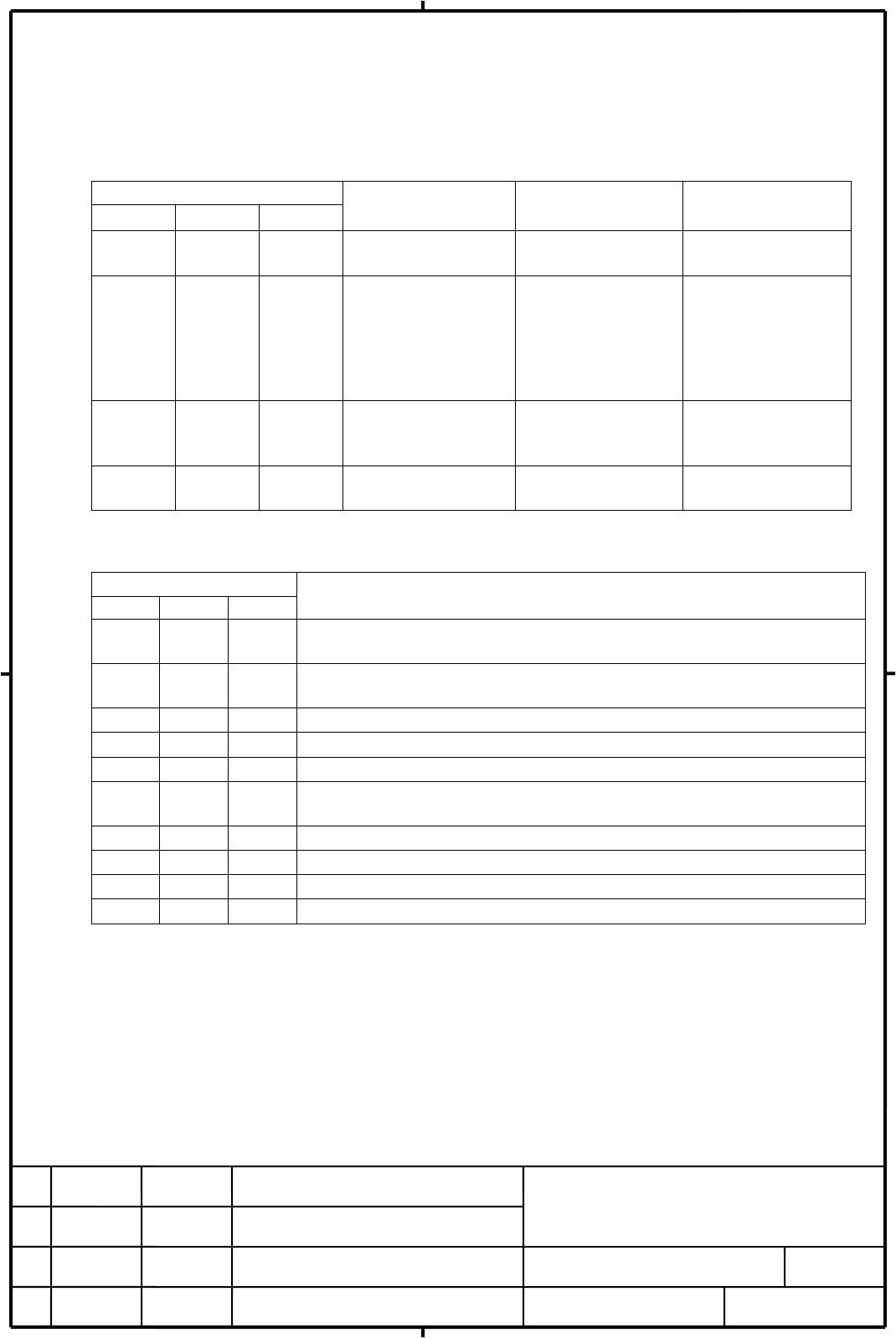
All spindle parameters of master and slave SPM except listed in table bellow should be same.
Parameter No.
15i 16i 30i
Description
Setting for
master SPM
Setting for
slave SPM
3002#3∼0 4002#3∼0 4002#3∼0
Spindle sensor type
depends on the
detector
depends on the
detector
3353#2 4353#2 4353#2
Relationship
between rotative
direction of master
motor and slave at
Torque Tandem
Control
Depends on the
spindle
configuration
0
3352#7,6 4352#7,6 4352#7,6
Setting of
communication
between SPMs
1, 0 0, 1
3360 4360 4360
Pre-load data
Depends on
machine
0
5.2. List of related parameters
Parameter No.
15i 16i 30i
Description
3009#2 4009#2 4009#2
Motor power turn-off method when SPM alarm 24 (serial data transfer
error )
3353#2 4353#2 4353#2
Relationship between rotative direction of master motor and slave at
Torque Tandem Control.
3015#3 4015#3 4015#3
Function bit of Spindle Tandem Control
3353#1 4353#1 4353#1
Setting of velocity feedback at Torque Tandem control
3398#3 4398#3 4398#3
Function bit of Twin Drive Control
3398#6 4398#6 4398#6
Setting of illegal velocity polarity alarm at Torque Tandem Control
(SPM alarm d0)
3352#6 4352#6 4352#6
Setting of slave axis of communication between SPMs
3352#7 4352#7 4352#7
Setting of master axis of communication between SPMs
3347 4347 4347
Detection level of speed difference between master/slave signal
3360 4360 4360
Pre-load data
Contents Summary of Spindle Amplifier Additional Manual
- Page 1Spindle Amplifier αi series Torque Tandem Control Description 1. General .............................................................................................................................................. 2 1.1. Overview ....................................................................
- Page 21. General 1.1. Overview This manual describes how to use Torque Tandem Control for spindle. 1.2. Remarks ・ Using this function requires αi series spindle amplifier module TYPE B. ・ Using this function requires CNC software option (Spindle Tandem Control). ・ Spindle amplifier modules (SPMs) and spin
- Page 33. System Configuration See ”FANUC SERVO AMPLIFIER αi series DESCRIPTIONS : B-65282EN” for detail connection of each cable. Notice * Emergency stop signal (connector CX4) must be prepared for each PSM. 3.1. Example 1 : master/slave spindles are coupled by workpiece TITLE Spindle Amplifier αi series
- Page 43.2. Example 2 : master / slave spindle drive the table axis TITLE Spindle Amplifier αi series Torque Tandem Control Description DRAW. No. CUST. 01 2004.11.30 M. Niwa Newly A-53866E-0450 SHEET Ed. Date Design. FANUC LTD 4/15
- Page 54. Input / Output Signals (CNC↔PMC) 4.1. Remarks ・ During tandem drive is active, input signals should be performed to master SPM. Specification of input signal is the same as normal spindle. See ”FANUC AC SPINDLE MOTOR αi series PARAMETER MANUAL : B-65280EN” for details. ・ No input PMC signal to sl
- Page 6It is not necessary to perform this signal for slave SPM when tandem drive is active (SLVx=1). Remark Motor power of master and slave spindle must be turned off immediately when abnormal condition is detected to minimize damage of machine. Be sure to turn off motor power in such situation. 4.3. Outp
- Page 715i 16i 30i #7 #6 #5 #4 #3 #2 #1 #0 1SP F231 F047 F047 MSOVRA 2SP F247 F051 F051 MSOVRB MSOVRA: Speed difference signal between master and slave (for 1st spindle) MSOVRB : Speed difference signal between master and slave (for 2nd spindle) 0 : Speed difference between master and slave is less than se
- Page 84.4. Example of sequence In following examples, 1st spindle : master SPM 2nd spindle : slave SPM are assumed. 4.4.1. example1 : velocity control mode TITLE Spindle Amplifier αi series Torque Tandem Control Description DRAW. No. CUST. 01 2004.11.30 M. Niwa Newly A-53866E-0450 SHEET Ed. Date Design. F
- Page 94.4.2. example2 : spindle orientation TITLE Spindle Amplifier αi series Torque Tandem Control Description DRAW. No. CUST. 01 2004.11.30 M. Niwa Newly A-53866E-0450 SHEET Ed. Date Design. FANUC LTD 9/15
- Page 104.4.3. example3 : rigid tapping TITLE Spindle Amplifier αi series Torque Tandem Control Description DRAW. No. CUST. 01 2004.11.30 M. Niwa Newly A-53866E-0450 SHEET Ed. Date Design. FANUC LTD 10/15
- Page 114.4.4. example4 : Cs contouring control TITLE Spindle Amplifier αi series Torque Tandem Control Description DRAW. No. CUST. 01 2004.11.30 M. Niwa Newly A-53866E-0450 SHEET Ed. Date Design. FANUC LTD 11/15
- Page 125. Related parameters 5.1. Remarks All spindle parameters of master and slave SPM except listed in table bellow should be same. Parameter No. Setting for Setting for 15i 16i 30i Description master SPM slave SPM depends on the depends on the 3002#3∼0 4002#3∼0 4002#3∼0 Spindle sensor type detector det
- Page 135.3. Details of related parameters 15i 16i 30i #7 #6 #5 #4 #3 #2 #1 #0 3009 4009 4009 ALSP ALSP Motor power turn-off method when SPM alarm 24 (serial data transfer error) is issued. 0 : Turns off the power after the motor is decelerated and stopped. 1 : Turns off the power to the motor immediately (
- Page 14RVSVC2 Relationship between rotative direction of master motor and slave at Torque Tandem Control. 0 : master motor and slave motor rotate in the same direction 1 : master motor and slave motor rotate in the opposite direction Set polarity of velocity command and velocity feedback at Torque Tandem C
- Page 1515i 16i 30i 3360 4360 4360 Pre-load data data unit : ±16384 is equivalent ±100% torque command data range : -8192 to 8192 (-50%~+50%) standard setting : 0 Set pre-load data. This parameter may be useful to reduce mechanical vibration. Remark It isn’t necessary to set this parameter of slave SPM (Set