FANUC Series 16i/18i/21i Additional Manual Page 9
Additional Manual
Page
Name
No.
FANUC Series 16i /18i /21i
–
TA/TB
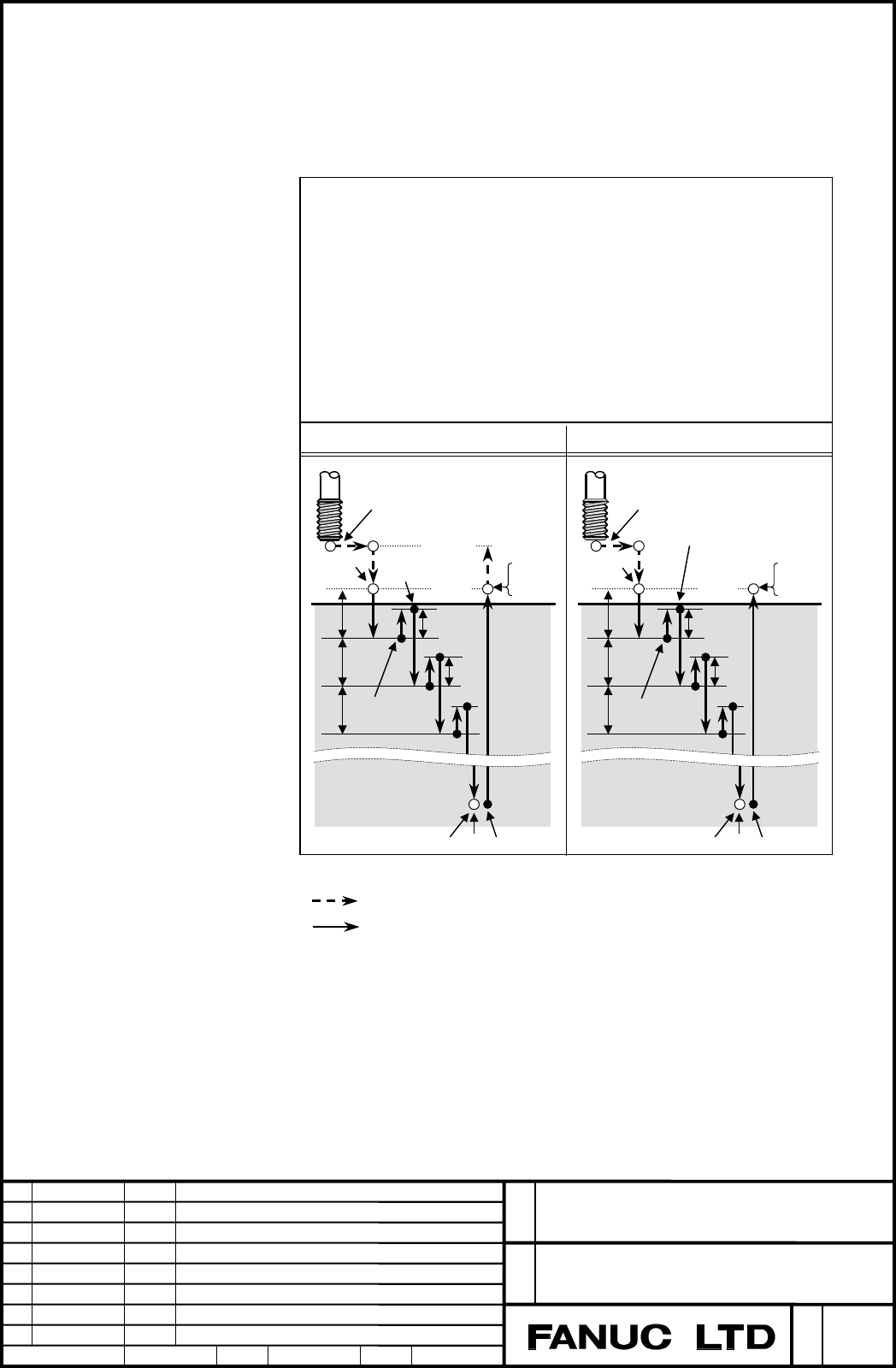
Peck tapping cycle (G84 or G88)
Specifications
A-78549E
3.3 HIGH-SPEED PECK RIGID TAPPING CYCLE
In case of the parameter PCP(No.5200#5)=0, if commanding G84/G88 as the rigid tapping,
the high-speed peck rigid tapping cycle is performed.
(Refer to the operator's manual etc. for the way of the rigid tapping command.)
Point Z
Point R
q
q
q
Ma
(1)
d
(2)
d
CCW
STOP
M(a+1)
P2
STOP
CCW
STOP
CW
C
W
P1
STOP
(3)
STOP
G84 or G88 (G code A or G98 mode)
G84 or G88 (G99 mode)
G84 X(U)_ C(H)_Z(W)_ R_ P_ Q_ F_ K_ M_ ;
or
G88 Z(W)_ C(H)_X(U)_ R_ P_ Q_ F_ K_ M_ ;
X_ C_ or Z_ C_ : Hole position data
Z_ or X_ : The distance from point R to the bottom of the hole and the position
of the bottom of the hole
R_ : The distance from the initial level to point R level
P_ : Dwell time at the bottom of the hole and at point R when a return is made
Q_ : Depth of cut for each cutting feed
F_ : The cutting feedrate
K_ : Number of repeats (if required)
M_ : M code for C-axis clamp (if required)
Point R
level
d = Return value
(3)
P1
STOP
C
W
Point R
Point Z
q
q
q
Ma
(1)
d
(2)
d
Initial
level
STOP
M(a+1)
P2
Point R
level
STOP
CW
STOP
CCW
CCW
STOP
- High-speed peck rigid tapping cycle
When the cut from Point R, Spindle rotates
to CW and only the distance q that was
commanded by address Q is performed.
(Operation (1))
After that, Spindle rotates to CCW and the
tool returns only about the distance d
(Return value) which was set to paramete
r
No.5213. (Operation (2))
After that, Spindle rotates to CW and the
cutting of distance (q+d) is performed.
(Operation (3))
After that, until the tip reaches hole-bottom
(Point Z), operation (2) and operation (3) are
repeated.
Then, a time constant number is used at the
rigid tapping time of the pull. Cutting speed
and a rigid tapping time constant are used
for operation (1) and operation (3)
Operation (2) and the movement from the
hole-bottom (Point Z) to the point R, the pull
override for the rigid tapping is available.
Each mark in the above figure shows the following operation.
P1
STOP
CW
CCW
Ma
M(a+1)
P2
Note P1, Ma, M(a+1) and P2 aren't executed (output) when there are not a
command/settin
g
.
: Positioning (rapid traverse G00)
: Cutting feed (linear interpolation G01)
: Dwell time which was commanded by the program by using the address P
: Spindle stop by CNC control (M code is not output.)
: Spindle CW rotation by CNC control (M code is not output.)
: Spindle CCW rotatiuon by CNC control (M code is not output.)
: M code for C-axis clamp is output ( a=Setting value of parameter No.5110 )
: M code for C-axis unclamp is output
: Dwell time which was set by parameter No.5111
Ed.
Date
Contents
Draw u
p
2004.06.09
9/16
Apprv.
Desig.
Desi
g
n
T. Kurokawa
Contents Summary of FANUC Series 16i/18i/21i Additional Manual
- Page 1FANUC Series 16i /18i /21i – TA/TB Peck tapping cycle (G84 or G88) Specifications Table of Contents 1 GENERAL ·············································································································2 2 SPECIFICATION································································
- Page 21 GENERAL When the deep hole cutting is executed by the tapping cycle or the rigid tapping cycle, the cutting may be difficult because that the chips gets entangled in tool or the cutting resistance increases. In this case, this function, such that the cutting is performed by moving from point R unt
- Page 32 SPECIFICATION When the parameter PCT (No.5104#6) is set to 1, this function is available. By setting the parameter PCP (No.5200#5), the tapping cycle type (high-speed peak tapping cycle or peak tapping cycle) is selected. And set return value (at high-speed peak tapping cycle) or clearance (cuttin
- Page 43 FORMAT 3.1 HIGH-SPEED PECK TAPPING CYCLE In case of the parameter PCP(No.5200#5)=0, if commanding G84/G88 as the tapping, the high-speed peck tapping cycle is performed. G84 X(U)_ C(H)_Z(W)_ R_ P_ Q_ F_ K_ M_ ; or G88 Z(W)_ C(H)_X(U)_ R_ P_ Q_ F_ K_ M_ ; X_ C_ or Z_ C_ : Hole position data Z_ or X
- Page 5Explanations This cycle operates as follows. 1. The tool is moved to the hole position in rapid traverse. 2. M code for C-axis clamp is output. (Only when M code for C-axis clamp is commanded.) 3. The tool is moved to the point R level in rapid traverse. 4. Cutting only distance q (depth of cut for
- Page 63.2 PECK TAPPING CYCLE In case of the parameter PCP(No.5200#5)=1, if commanding G84/G88 as the tapping, the peck tapping cycle is performed. G84 X(U)_ C(H)_Z(W)_ R_ P_ Q_ F_ K_ M_ ; or G88 Z(W)_ C(H)_X(U)_ R_ P_ Q_ F_ K_ M_ ; X_ C_ or Z_ C_ : Hole position data Z_ or X_ : The distance from point R t
- Page 7Explanations This cycle operates as follows. 1. The tool is moved to the hole position in rapid traverse. 2. M code for C-axis clamp is output. (Only when M code for C-axis clamp is commanded.) 3. The tool is moved to the point R level in rapid traverse. 4. Cutting only distance q (depth of cut for
- Page 8Cutting start distance Cutting start distance (d) is the value which is set to parameter (No.5213). Return speed to Point R Cutting speed to Cutting start point The speed of the return operation to Point R and the speed of the cutting feed to cutting start point are the same as the speed of the cutt
- Page 93.3 HIGH-SPEED PECK RIGID TAPPING CYCLE In case of the parameter PCP(No.5200#5)=0, if commanding G84/G88 as the rigid tapping, the high-speed peck rigid tapping cycle is performed. (Refer to the operator's manual etc. for the way of the rigid tapping command.) G84 X(U)_ C(H)_Z(W)_ R_ P_ Q_ F_ K_ M_
- Page 10Explanations This cycle operates as follows. 1. Spindle is stop. 2. The tool is moved to the hole position in rapid traverse. 3. M code for C-axis clamp is output. (Only When M code for C-axis clamp is commanded.) 4. The tool is moved to the point R level in rapid traverse. 5. Spindle rotates to CW
- Page 113.4 PECK RIGID TAPPING CYCLE In case of the parameter PCP(No.5200#5)=1, if commanding G84/G88 as the rigid tapping, the peck rigid tapping cycle is performed. (Refer to the operator's manual etc. for the way of the rigid tapping command.) G84 X(U)_ C(H)_Z(W)_ R_ P_ Q_ F_ K_ M_ ; or G88 Z(W)_ C(H)_X(
- Page 12Explanations This cycle operates as follows. 1. Spindle is stop. 2. The tool is moved to the hole position in rapid traverse. 3. M code for C-axis clamp is output. (Only When M code for C-axis clamp is commanded.) 4. The tool is moved to the point R in rapid traverse. 5. Spindle rotates to CW. And c
- Page 13Cutting start distance Cutting start distance (d) is the value which is set to parameter (No.5213). Return speed to Point R Cutting speed to Cutting start point Like the movement from the bottom of hole (Point Z) to Point R (above 14.), the overriding (Max. 2000 % ) is available with the return spee
- Page 144 PARAMETER #7 #6 #5 #4 #3 #2 #1 #0 05104 PCT [Data type] Bit #6 PCT Address Q command about tapping cycle (G84/G88) is 0: Not available 1: Available ( = Peck tapping cycle ) A peck tapping cycle is performed when setting this parameter and the depth of each cutting is commanded by using the address
- Page 1505213 Return or clearance in peck tapping cycle [Data type] Word [Unit of data] Increment System IS-B IS-C IS-D Unit Millimeter input 0.001 0.001 0.001 mm Input input 0.0001 0.0001 0.0001 inch [Valid data range] 0 to 32767 This parameter sets the return or clearance in the peck tapping cycle. Set a
- Page 165 NOTES (1) In the following cases the peck tapping cycle is not performed. Instead, ordinary tapping cycle or rigid tapping cycle is performed. • When Q is not specified. • When Q0 is specified. (2) When the F15 tape format is effective, when adding address Q to G84.2, the peck tapping cycle by G84