FANUC MODBUS/TCP Additional Manual Page 60
Additional Manual
A-90188E-01 MAINTENANCE 1.Series 16i/18i/21i MAINTENENCE INFORMATION
- 58 -
1.1.2 LED Indications
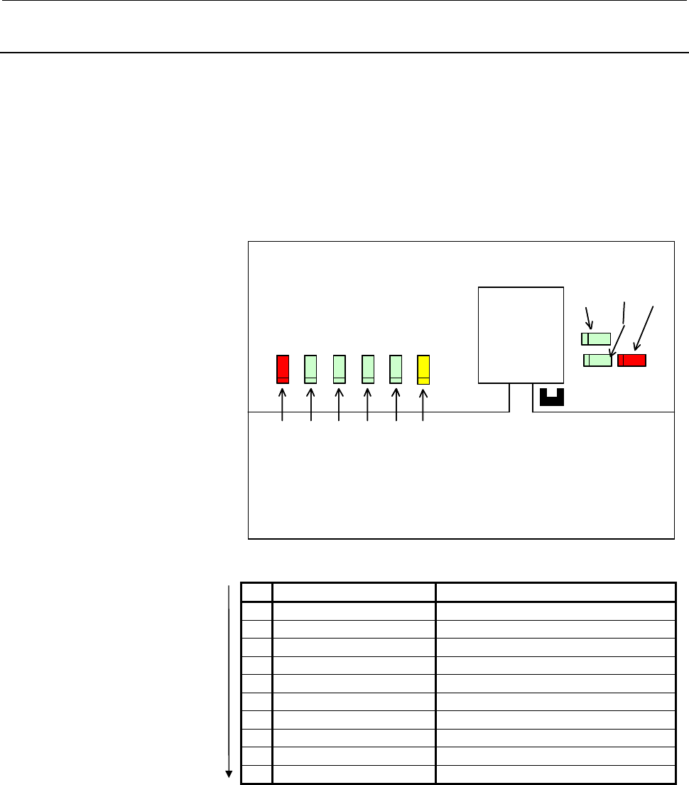
The MODBUS/TCP board for LCD-mounted type 16i/18i/21i
incorporates the following LEDs: Four green STATUS LEDs and one
red ALARM LED for indicating the status. Two green LEDs, one
yellow LED, and one red LED for indicating the communication
status. The figure below shows the locations of these LEDs. The table
below explains the LED lighting states.
In the following explanations, the LED lighting states are expressed as
follows:
□: Off ■: On ☆: Blinking ◊: Don't care
LED lighting sequence at power on
No. LED indication
1234 MODBUS/TCP board state
1
STATUS
□□□□
Power off
2
STATUS
■■■■
Initial state after power on
3
STATUS
□■■■
MPU initialized.
4
STATUS
□□■■
Firmware downloaded.
5
STATUS
□□□■
Control migration to OS
6
STATUS
■■■□
OS PHASE1
7
STATUS
□■■□
OS PHASE2
8
STATUS
■□■□
OS PHASE3
9
STATUS
□□■□
OS PHASE4
10
STATUS
☆□□□
Startup completed.
The system enters the No.10 status when the MODBUS/TCP board
starts normally. This status is maintained until an error occurs.
CD38V
LED3 (GREEN)
LED2 (GREEN)
LED1 (GREEN)
AL M (R ED)
BTX (GREEN)
COL (RED)
LED4 (GREEN)
LIL (GREEN)
COM (YELLOW)
CD38V
LED3 (GREEN)
LED2 (GREEN)
LED1 (GREEN)
AL M (R ED)
BTX (GREEN)
COL (RED)
LED4 (GREEN)LED4 (GREEN)
LIL (GREEN)
COM (YELLOW)
Contents Summary of FANUC MODBUS/TCP Additional Manual
- Page 1TECHNICAL REPORT(MANUAL) NO.TMN 05/ Date 9. Sep. 2005 General Manager of Software Research Laboratory FANUC MODBUS/TCP Board OPERATOR’S MANUAL For FANUC Series 16i/160i/160is–MODEL B, FANUC Series 18i/180i/180is–MODEL B5, FANUC Series 18i/180i/180is–MODEL B, FANUC Series 21i/210i/210is–MODEL B 1. Co
- Page 2FANUC MODBUS/TCP Board OPERATOR'S MANUAL For FANUC Series 16i/160i/160is–MODEL B, FANUC Series 18i/180i/180is–MODEL B5, FANUC Series 18i/180i/180is–MODEL B, FANUC Series 21i/210i/210is–MODEL B 1.Type of applied technical documents Name FANUC MODBUS/TCP Board OPERATOR'S MANUAL For FANUC Series 160i/1
- Page 3A-90188E-01 SAFETY PRECAUTIONS SAFETY PRECAUTIONS This section describes the safety precautions related to the use of CNC units, to ensure safe operation of machines fitted with FANUC CNC units. Read this section carefully before attempting to use any function described in this manual. Users should
- Page 4A-90188E-01 SAFETY PRECAUTIONS 1.1 DEFINITION OF WARNING, CAUTION, AND NOTE This manual includes safety precautions for protecting the user and preventing damage to the machine. Precautions are classified into Warnings and Cautions according to their bearing on safety. Also, supplementary informatio
- Page 5A-90188E-01 SAFETY PRECAUTIONS 1.2 GENERAL WARNINGS AND NOTES WARNING 1 Before operating the machine, thoroughly check the entered data. Operating the machine with incorrectly specified data may result in the machine behaving unexpectedly, possibly causing damage to the workpiece and/or machine itse
- Page 6A-90188E-01 SAFETY PRECAUTIONS CAUTION 1 Immediately after switching on the power, do not touch any of the keys on the MDI panel until the position display or alarm screen appears on the CNC unit. Some of the keys on the MDI panel are dedicated to maintenance or other special operations. Pressing an
- Page 7A-90188E-01 TABLE OF CONTENTS TABLE OF CONTENTS SAFETY PRECAUTIONS............................................................................................................... 1 1.1 DEFINITION OF WARNING, CAUTION, AND NOTE.............................................. 2 1.2 GENERAL WARNINGS AND NO
- Page 8A-90188E-01 TABLE OF CONTENTS 3.5.2 Clamping and Shielding Cables ........................................................................... 50 3.5.3 Grounding the Network ........................................................................................ 53 IV. MAINTENANCE ...................
- Page 9I. GENERAL -7-
- Page 10A-90188E-01 GENERAL 1.GENERAL 1 GENERAL This manual describes the MODBUS/TCP functions of the FANUC Series 16i/160i, 18i/180i, 21i/210i-B. This chapter explains the organization of this manual and applied models. -8-
- Page 11A-90188E-01 GENERAL 1.GENERAL 1.1 ORGANIZATION This manual consists of the following parts: SAFETY PRECAUTIONS This section describes the precautions to be observed when reading this manual. I. GENERAL This section describes the chapter organization, applicable models, and related manuals. II. SETTI
- Page 12A-90188E-01 GENERAL 1.GENERAL 1.2 APPLICABLE MODELS This Operator's Manual covers the following models. The abbreviations in the following table are sometimes used in text descriptions. Model name Abbreviation FANUC Series 16i-MODEL B Series 16i-B 16i-B FANUC Series 160i-MODEL B 16i-B Series 160i-B
- Page 13A-90188E-01 GENERAL 1.GENERAL 1.3 RELATED MANUALS The table below lists manuals related to this Operator's Manual. Refer to these manuals when you use this Operator's Manual. Specification Manual name number DESCRIPTIONS B-63522EN CONNECTION MANUAL (HARDWARE) B-63523EN CONNECTION MANUAL (FUNCTION) B
- Page 14A-90188E-01 GENERAL 2.OVERVIEW OF MODBUS/TCP FUNCTION 2 OVERVIEW OF MODBUS/TCP FUNCTION FANUC MODBUS/TCP function supports Server function. This chapter explains the outline of FANUC MODBUS/TCP Server function. NOTE FANUC MODBUS/TCP function does not support Client function. MODBUS Data model The fo
- Page 15A-90188E-01 GENERAL 2.OVERVIEW OF MODBUS/TCP FUNCTION Access to the MODBUS area (Holding registers) As the following figure, when user application (such as Ladder program) accesses the MODBUS area (Holding registers), it accesses through the PMC area in the FANUC MODBUS/TCP Server function. MODBUS/T
- Page 16A-90188E-01 GENERAL 2.OVERVIEW OF MODBUS/TCP FUNCTION - For the available PMC area: - If the PMC’s type is PMC-SD7, the available PMC area is %M, %ME, or %R. - If the PMC’s type is PMC-SB7, the available PMC area is R, E, or D. Server design of MODBUS/TCP function The Server design of FANUC MODBUS/T
- Page 17II. SETTING - 15 -
- Page 18A-90188E-01 SETTING 1.MODBUS/TCP SERVER FUNCTION 1 MODBUS/TCP SERVER FUNCTION This chapter describes how to set MODBUS/TCP Sever function. CAUTION After setting DI/DO data, make sure communication is performed correctly in a state in which security is retained. Operating the system without confirmat
- Page 19A-90188E-01 SETTING 1.MODBUS/TCP SERVER FUNCTION 1.1 SETTING SCREEN OF MODBUS/TCP SERVER FUNCTION MODBUS/TCP Server function has two setting screens; COMMON screen and SERVER screen. NOTE When setting parameters, confirm that it is the MDI mode. After setting the parameters, be sure to power off the
- Page 20A-90188E-01 SETTING 1.MODBUS/TCP SERVER FUNCTION NOTE When "POWER ON ERROR" is displayed on this screen, remove an error factor on the LOG screen, and turn on the power again. Refer to Section 1.2, "MAINTENANCE SCREEN MODBUS/TCP FUNCTION" for the LOG screen. COMMON screen Procedure 1 Press soft key
- Page 21A-90188E-01 SETTING 1.MODBUS/TCP SERVER FUNCTION Setting item Item Description Parameter No IP ADDRESS Specify the IP address of Pa10 MODBUS/TCP Server. (Example of specification format : "192.168.0.1") SUBNET MASK Specify a mask address for the IP Pa11 addresses of the network. (Example of specific
- Page 22A-90188E-01 SETTING 1.MODBUS/TCP SERVER FUNCTION SERVER screen Precedure 1 Press soft key [SERVER] to display SERVER screen (SCREEN1-3). 2 Move the cursor to the item to set and then enter the parameter. 3 When this screen is 9-inch screen, this screen can be changed with Page key PAGE . PAGE SCREEN
- Page 23A-90188E-01 SETTING 1.MODBUS/TCP SERVER FUNCTION Setting item Item Description Parameter No BASIC PORT NUMBER Specify the port number to be used by the Pa20 (TCP) MODBUS/TCP Server function. The available range is form 0 to 65535. The default listening port number is 502. STATUS PMC Specify PMC addr
- Page 24A-90188E-01 SETTING 1.MODBUS/TCP SERVER FUNCTION Item Description Parameter No AREA1-3 DATA SIZE Specify the I/O size to exchange I/O data with AREA1:Pa33 (WORD) MODBUS/TCP clients. AREA2:Pa43 A unit is 16-bit word. AREA3:Pa53 A range is the following. For a PMC address %M or %ME: The available rang
- Page 25A-90188E-01 SETTING 1.MODBUS/TCP SERVER FUNCTION Data encoding of MODBUS area (Holding Registers) When Bit 0 of OPTION1 parameter is OFF, the addresses and data items of MODBUS area are encoded as a “little-endian”. On the Ethernet line MODBUS Area PMC Area (Hold ing Reg isters) 0 15 15 0 7 0 +00 12
- Page 26A-90188E-01 SETTING 1.MODBUS/TCP SERVER FUNCTION Status The status is detected by MODBUS/TCP Server function. Status STATUS PMC ADDRESS MODBUS Status (1 byte) MODBUS Status Bit 0 :Some unrecoverable error occurred in MODBUS board (Error status). Bit 1 to Bit 5: Reserved Bit 6 :The initialization of
- Page 27A-90188E-01 SETTING 1.MODBUS/TCP SERVER FUNCTION 1.2 MAINTENANCE SCREEN OF MODBUS/TCP SERVER FUNCTION The maintenance screens of MODBUS/TCP Server function has COMMUNICATION STATE screen, CONNECTION INFORMATION screen and MODBUS LOG screen. In COMMUNICATION STATE screen, communication status detecte
- Page 28A-90188E-01 SETTING 1.MODBUS/TCP SERVER FUNCTION COMMUNICATION STATE screen Procedure 1 Press soft key [STATE] to display COMMUNICATION STATE screen (SCREEN1-5). 2 When this screen is 9-inch screen, this screen can be changed with Page key PAGE . PAGE SCREEN 1 - 5 - 26 -
- Page 29A-90188E-01 SETTING 1.MODBUS/TCP SERVER FUNCTION Display items Item Description BAUDRATE Displays the communication rate and mode. Communication rate : 100Mbps or 10Mbps Communication mode : Full duplex or Half duplex SEND PACKET Displays the number of sent packets. SEND Displays the number of error
- Page 30A-90188E-01 SETTING 1.MODBUS/TCP SERVER FUNCTION CONNECTION INFORMATION screen Procedure 1 Press soft key [INFORM] to display CONNECTION INFORMATION screen (SCREEN 1-6). 2 When this screen is 9-inch screen, this screen can be changed with Page key PAGE . PAGE SCREEN 1 - 6 Display item Item Descripti
- Page 31A-90188E-01 SETTING 1.MODBUS/TCP SERVER FUNCTION MODBUS LOG screen Precedure 1 Press soft key [LOG] to display MODBUS LOG screen(SCREEN 1-7). 2 The page of LOG screen can be changed with Page key PAGE . PAGE SCREEN 1 - 7 The latest log information is displayed at the top of the screen. At the right
- Page 32A-90188E-01 SETTING 1.MODBUS/TCP SERVER FUNCTION Error number Log message Meaning and action to be taken E-041A FRAME TRANSMISSION FAILED (TCP) The transmission of the frame was unsuccessful. (TCP) A communication error occurred due to one of the following causes: → The network quality degraded, dat
- Page 33A-90188E-01 SETTING 1.MODBUS/TCP SERVER FUNCTION Error number Log message Meaning and action to be taken E-0B03 SUBNET MASK IS NOT SET The subnet mask is not set. Set the subnet mask. E-0B04 ROUTER IP ADDRESS IS WRONG. The router IP address is wrong. There may be a conflict between the classes of th
- Page 34A-90188E-01 SETTING 1.MODBUS/TCP SERVER FUNCTION 1.3 NOTES ON CREATING A LADDER PROGRAM The following provides notes on creating a ladder program required to construct a safety system in a system that uses MODBUS/TCP. Data concurrency When a ladder program uses data in long data (4-byte data) units
- Page 35A-90188E-01 SETTING 1.MODBUS/TCP SERVER FUNCTION Concurrency of word data (2-byte data) To ensure data concurrency, the following two conditions must be observed: (1) In the ladder program, the following instructions must be used in units of two bytes: DECB, CODEB, DCNVB, COMPB, DSCHB, XMOVB, ADDB,
- Page 36III. CONNECTION - 34 -
- Page 37A-90188E-01 CONNECTION 1.SETTING 1 SETTING This chapter describes the information needed to install the MODBUS/TCP board. - 35 -
- Page 38A-90188E-01 CONNECTION 1.SETTING 1.1 ENVIRONMENTAL CONDITIONS FOR INSTALLING A CNC A CNC in which the MODBUS/TCP board is installed must be used in the following environment. Condition MODBUS/TCP board 0°C to 55°C Operation (Note 2) Ambient (0°C to 58°C) temperature Storage or -20°C to 60°C transpor
- Page 39A-90188E-01 CONNECTION 1.SETTING 1.2 POWER SUPPLY CAPACITY AND HEAT DISSIPATION The power supply capacities and the heat dissipation of the MODBUS/TCP board are indicated below. For the power supply capacities and the heat dissipation of the main CNC unit and other optional units, refer to the conne
- Page 40A-90188E-01 CONNECTION 2.INSTALLATION 2 INSTALLATION This chapter provides information relating to the installation of the MODBUS/TCP board. - 38 -
- Page 41A-90188E-01 CONNECTION 2.INSTALLATION 2.1 LCD-MOUNTED TYPE Series 16i/18i/21i-B This section provides information on installing the MODBUS/TCP board in the LCD-mounted type Series 16i/18i/21i-B. 2.1.1 Installing an Board An option board such as the MODBUS/TCP board is installed in an option slot of
- Page 42A-90188E-01 CONNECTION 2.INSTALLATION 2.2 STAND-ALONE TYPE Series 16i/18i/21i-B This section provides information on installing the the MODBUS/TCP board in Stand-alone type Series 16i/18i/21i-B. 2.2.1 Installing an Board The MODBUS/TCP board can be installed in a mini slot of the one-slot or three-s
- Page 43A-90188E-01 CONNECTION 2.INSTALLATION 2.3 Total Connection Diagram MODBUS/TCP Board CD38V 1 TX+ 2 TX- 3 RX+ HUB 4 5 6 RX- 7 8 - 41 -
- Page 44A-90188E-01 CONNECTION 3.HARDWARE CONNECTIONS 3 HARDWARE CONNECTIONS This section describes information relating to the physical Ethernet connection. CAUTION 1 Before connecting or disconnecting cables to and from the MODBUS/TCP board, cut the power supply of CNC. 2 Please inquire of each manufactur
- Page 45A-90188E-01 CONNECTION 3.HARDWARE CONNECTIONS 3.1 CONNECTING TO ETHERNET The MODBUS/TCP board or Fast data server is provided with a 100BASE-TX interface. Prepare a hub for connecting the MODBUS/TCP board to the Ethernet trunk. The following shows an example of a general connection. Switching HUB HU
- Page 46A-90188E-01 CONNECTION 3.HARDWARE CONNECTIONS 3.2 LEADING OUT THE ETHERNET CABLE 1) Stand-alone type Series 16i/18i/21i-B For this type of control unit, the cable is led out from the bottom of the control unit. See the outline drawing of the board for the location of the connector. Control unit Twis
- Page 47A-90188E-01 CONNECTION 3.HARDWARE CONNECTIONS 3.3 100BASE-TX CONNECTOR (CD38V) PIN ASSIGNMENTS CD38V Pin No. Signal name Description 1 TX+ Send + 2 TX− Send − 3 RX+ Receive + 4 Not used 5 Not used 6 RX− Receive − 7 Not used 8 Not used - 45 -
- Page 48A-90188E-01 CONNECTION 3.HARDWARE CONNECTIONS 3.4 TWISTED-PAIR CABLE SPECIFICATION 3.4.1 Cable Connection The figure below shows the cable connection between the 100BASE-TX interface (CD38V) on the MODBUS/TCP board and hub. MODBUS/TCP Board CD38V HUB 1 TX+ RJ-45 1 TX+ 2 TX- Modular connector 2 TX- 3
- Page 49A-90188E-01 CONNECTION 3.HARDWARE CONNECTIONS 3.4.2 Cable Materials CAUTION Unshielded cable (UTP cable) is commercially available as 100BASE-TX twisted-pair cable: You should, however, use shielded Category 5 twisted-pair cable (STP cable) to improve the resistance to electrical noise in an FA envi
- Page 50A-90188E-01 CONNECTION 3.HARDWARE CONNECTIONS Recommended cable (for movable parts) Manufacturer Specification Remarks Oki Electric Cable Co., Ltd. AWG26 4P TPMC-C5-F(SB) Dedicated to FANUC Cable specification (originally designed for FANUC, with no connector) Drawing number: A66L-0001-0453 Manufact
- Page 51A-90188E-01 CONNECTION 3.HARDWARE CONNECTIONS 3.4.3 Connector Specification Use an 8-pin modular connector (RJ-45) with the twisted-pair cable for the Ethernet connection. The following connectors or equivalents must be used. Specification Manufacturer Remarks Solid wire 5-569530-3 AMP Japan, Ltd. S
- Page 52A-90188E-01 CONNECTION 3.HARDWARE CONNECTIONS 3.5 ELECTRICAL NOISE COUNTERMEASURES 3.5.1 Separating Signal Lines For signal line separation, refer to the description of noise protection in the connection manual (part for hardware) of each CNC. The wiring for the Ethernet cable is of group C. 3.5.2 C
- Page 53A-90188E-01 CONNECTION 3.HARDWARE CONNECTIONS Control unit Twisted-pair cable Ground plate Clamp fixture Outer coating of shield Example of Shielding of Transceiver Cable Prepare the following earth plate. Mounting screw hole Ground terminal Clamp fixture (used for mounting hole grounding) Use a nic
- Page 54A-90188E-01 CONNECTION 3.HARDWARE CONNECTIONS 8 mm Ground plate 12 mm 20 mm Details of Clamp Fixture Mounting Holes 55 mm max. 28mm 6mm 17mm External Dimensions of Clamp Fixture Clamp Fixture Procurement Specifications A02B-0083-K301 (Twenty clamp fixtures) - 52 -
- Page 55A-90188E-01 CONNECTION 3.HARDWARE CONNECTIONS 3.5.3 Grounding the Network Even if the grounding conditions on the machine are satisfied, electrical noise from the machine sometimes enters the communications line and causes communications interference depending on the installation conditions and the
- Page 56A-90188E-01 CONNECTION 3.HARDWARE CONNECTIONS NOTE 1 The ground between PC/HUB side and machine system side must be separated. If it is impossible to separate the ground because there is only one grounding point, connect the ground cable for each system to the grounding point independently. (Refer F
- Page 57IV. MAINTENANCE - 55 -
- Page 58A-90188E-01 MAINTENANCE 1.Series 16i/18i/21i MAINTENENCE INFORMATION 1 Series 16i/18i/21i MAINTENENCE INFORMATION This chapter describes the maintenance information for MODBUS/TCP board for 16i/18i/21i-B. - 56 -
- Page 59A-90188E-01 MAINTENANCE 1.Series 16i/18i/21i MAINTENENCE INFORMATION 1.1 MODBUS/TCP BOARD FOR LCD-MOUNTED TYPE CNC This section describes the maintenance information for the MODBUS/TCP board for the LCD-mounted type 16i/18i/21i-B. 1.1.1 Component Layout Name Specification Remarks MODBUS/TCP board A2
- Page 60A-90188E-01 MAINTENANCE 1.Series 16i/18i/21i MAINTENENCE INFORMATION 1.1.2 LED Indications The MODBUS/TCP board for LCD-mounted type 16i/18i/21i incorporates the following LEDs: Four green STATUS LEDs and one red ALARM LED for indicating the status. Two green LEDs, one yellow LED, and one red LED fo
- Page 61A-90188E-01 MAINTENANCE 1.Series 16i/18i/21i MAINTENENCE INFORMATION STATUS LED indications if an error occurs If an error occurs, the LEDs repeatedly flash "LONG" then "SHORT." (For "LONG," the LED lights for a long time. For "SHORT," the LED lights for a short time.) STATUS LED indication No. MODB
- Page 62A-90188E-01 MAINTENANCE 1.Series 16i/18i/21i MAINTENENCE INFORMATION 1.2 MODBUS/TCP BOARD FOR STAND-ALONE TYPE CNC This section describes the maintenance information for the MODBUS/TCP board for the Stand-alone type Series 16i/18i/21i-B. 1.2.1 Component Layout CD38V Name Specification Remarks MODBUS
- Page 63A-90188E-01 MAINTENANCE 1.Series 16i/18i/21i MAINTENENCE INFORMATION 1.2.2 LED Indications The MODBUS/TCP board for the Stand-alone type CNC has the following LEDs: Four green STATUS LEDs and one red ALARM LED for indicating the status. Three green LEDs and one red LED for indicating the communicati
- Page 64A-90188E-01 MAINTENANCE 1.Series 16i/18i/21i MAINTENENCE INFORMATION STATUS LED indications if an error occurs If an error occurs, the LEDs repeatedly flash "LONG" then "SHORT." (For "LONG," the LED lights for a long time. For "SHORT," the LED lights for a short time.) STATUS LED indication No. MODB
- Page 65APPENDIX - 63 -
- Page 66A-90188E-01 APPENDIX SETTING METHOD FOR PMC-SB7 A SETTING METHOD FOR PMC-SB7 This chapter describes the setting method when PMC-SB7 is used. NOTE PMC-SB7 is different from PMC-SD7 only about the PMC address setting. The Setting item for the PMC address setting is equal to “STATUS PMC ADDRESS”, “DATA
- Page 67A-90188E-01 APPENDIX SETTING METHOD FOR PMC-SB7 A.1 PMC ADDRESS SETTING FOR SERVER SCREEN The Example of PMC address setting for SERVER screen descibes below when PMC-SB7 is used. - 65 -
- Page 68A-90188E-01 APPENDIX SETTING METHOD FOR PMC-SB7 Setting item of PMC address for PMC-SB7 Item Description BASIC STATUS PMC Specify PMC address to set MODBUS status. ADDRESS If the status information is not necessary, specify a space character (SP). The available PMC area is R and E. AREA1-3 DATA PMC
- Page 69A-90188E-01 APPENDIX SETTING METHOD FOR PMC-SB7 A.2 NOTES ON CREATING A LADDER PROGRAM FOR PMC-SB7 The following provides notes on creating a ladder program required to construct a safety system in a system that uses MODBUS/TCP. Data concurrency When a ladder program uses data in long data (4-byte d