Beta i SVPM Descriptions Additional Manual Page 29
Additional Manual
5.TOTAL CONNECTION DIAGRAM A-72562EN-027
- 28 -
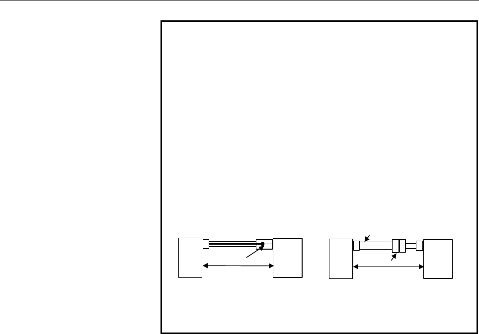
NOTE
1 Please place the ground plate connected the shield near SVPM and
shorten the distance between SVPM and groud plate as possible
2 The ground plate to which the shield is connected must be placed as
close as possible to the servo amplifier so that distance between the
ground plate and the servo amplifier becomes shortest.
3
In case that the cable is prepared by MTB, total resistance
of 5V and 0V must be less than 2Ω.
4
Pulsecoder side connector can accept maximum 0.5mm
2
(wire construction 20/0.18 or 104/0.08, diameter φ1.5 or
less) wire and sheath diameter is φ5.7 to φ8.0. In case of
using thicker wire or cable, take measures described below.
The total resistance (Round
trip) of 5 V and 0 V must be
less than 2
Ω
.
[Case 1] Cable conductor exceeds 0.5mm
2
. [Case 2] Sheath diameter of exceeds
φ
8.
Soldering or crimping
Servo motor
SVM
Connector
Cable thicker than
φ
8
SVM
Servo motor
The total resistance (Round
trip) of 5 V and 0 V must be
less than 2
Ω
.
5
In case of incremental Pulsecoder, 6V is not necessary to be
connected.
• Crimp tool specification
A06B-6114-K201/JN1S : For 0.3 mm
2
A06B-6114-K201/JN1L : For 0.18 mm
2
or 0.5 mm
2
• Connector kit specification
A06B-6114-K204/S : Straight plug (including a contact)
A06B-6114-K204/E : Elbow plug (including a contact)
• Recommended cable
A66L-0001-0460 : Flexible cable length 28m or less
A66L-0001-0462 : Flexible cable length 50m or less
A66L-0001-0481 : Fixed cable length 28m or less
A66L-0001-0491 : Fixed cable length 50m or less
Contents Summary of Beta i SVPM Descriptions Additional Manual
- Page 1TECHNICAL REPORT (MANUAL) NO. TMS03/019E Date 2003.05.16 General Manager of Laboratory βi SVPM Descriptions 1. Communicate this report to: Your information only ○ GE Fanuc-N, GE Fanuc-E FANUC Robotics MILACRON ○ Machine tool builder Sales agency ○ End user ○ SLB4 2. Summary for Sales Documents 3. No
- Page 21.CONFIGURATIONA-72562EN-027 1 CONFIGURATION System Configuration of beta i SVPM FAN UNIT FAN UNIT SVPM JF1 Servo Motor Pulse Coder I/F JF2 Servo Motor JF3 Servo Motor JX6 CX3 JY1 LM, SM, OVR CX4 JA7A CNC ESP Spindle I/F JA7B CNC CXA2C 24V SUPPLY JYA2 Spindle Motor Battery CX5X Spindle Sensor JYA3 P
- Page 32.SPECIFICATIONS A-72562EN-027 2 SPECIFICATIONS Item Specification Power supply voltage Three-phase 200 VAC to 240 VAC for the main circuit Power supply voltage DC24V/1.5A for the control circuit Dynamic brake built-in Spindle sensor TYPE A :SVPM*-**i/A Without feed back :SVPM*-**i/C CNC FS 0i MODEL
- Page 42.SPECIFICATIONSA-72562EN-027 (3) It is recommended that a capacitor unit for power-factor improvement is not be installed. This is because the capacitor unit for power-factor improvement may adversely affect power regeneration. (4) The rated output of the motor is guaranteed for the rated input vol
- Page 52.SPECIFICATIONS A-72562EN-027 Applied Motor Spindle Motor Servo Motor β 3/10000i β 6/10000i β 8/8000i β 12/7000i β 2/4000is β 4/4000is β 8/3000is β 12/3000i β 22/2000i SVPM2-5.5i Spindle o Servo L axis o o o Servo M axis o o o SVPM2-11i Spindle * o o Servo L axis o o o Servo M axis o o o SVPM2-15i
- Page 62.SPECIFICATIONSA-72562EN-027 Types (A and B) of Spindle and sensors applicable to each type Either of two SPM models, types A and C, is available for each detector on the spindle to be used. The following lists combinations of an SVPM type, applicable sensors, and functions. STRUCTURE Remark 1 2 3
- Page 72.SPECIFICATIONS A-72562EN-027 JY1 Connector Analog output of load meter OR speedometer O JY1 Connector Analog override input O O JY1 -6-�
- Page 82.SPECIFICATIONSA-72562EN-027 ENVIRONMENTAL CONDITIONS The servo amplifier beta i series must be installed in a sealed type cabinet to satisfy the following environmental requirements: (1) Ambient Temperature Ambient temperature of the unit : 0 to 55°C (at operation) -20 to 60°C (at keeping and tran
- Page 92.SPECIFICATIONS A-72562EN-027 (d) Current lines and signal lines must be separated and noise must be suppressed. See the section 5.3 and the connection manual for each CNC for details. (f) Each amplifier must be installed vertically. (g) Servo amplifiers are to be arranged horizontally. When arrang
- Page 103.ORDERING INFORMATIONA-72562EN-027 3 ORDERING INFORMATION Refer to the ordering list B-65321EN. -9-�
- Page 114.EXTERNAL DIMENSIONS, PANEL CUT-OUTDIAGRAM, AND MAINTENANCE AREA A-72562EN-027 4 EXTERNAL DIMENSIONS, PANEL CUT-OUTDIAGRAM, AND MAINTENANCE AREA - 10 -�
- Page 124.EXTERNAL DIMENSIONS, PANEL CUT-OUTDIAGRAM, AND MAINTENANCE AREAA-72562EN-027 4.1 OUTLINE DRAWINGS 4.1.1 SVPM 380mm 260mm 172mm 92.5 mm max Weight:14.8kg 4.1.2 FAN UNIT (A06B-6134-K001) 120 mm AC 200V IN (47mm) 85 mm 145 mm 60 mm 100 mm 21.5 mm - 11 -�
- Page 134.EXTERNAL DIMENSIONS, PANEL CUT-OUTDIAGRAM, AND MAINTENANCE AREA A-72562EN-027 4.2 Panel cut-out FAN UNIT (A06B-6134-K001) (1) FAN unit is not installed (2) One FAN unit is installed (3) Two FAN units are installed 135 135 12 135 131 7.5 131 131 7.5 16 60 75 20 60 75 20 2 2 11 4-M4 10 11 4-M4 10 11
- Page 144.EXTERNAL DIMENSIONS, PANEL CUT-OUTDIAGRAM, AND MAINTENANCE AREAA-72562EN-027 4.3 MAINTENANCE AREA (1)Without FAN UNIT AIR FLOW AIR FLOW AIR FLOW (note) 260 mm 50mm 172 mm 100 mm 50 mm 380 mm 50mm (Note) With sideways cable slot type. Add 30mm when using the conventional type (2)With FAN UNIT AIR F
- Page 154.EXTERNAL DIMENSIONS, PANEL CUT-OUTDIAGRAM, AND MAINTENANCE AREA A-72562EN-027 4.4 DUCT How to install FAN UNIT A06B-6134-K001. Note Duct like the following form shall be installed between the fan unit and the amplifier for cooling. The duct shall be weld on to the cabinet. (1) When one unit is ins
- Page 164.EXTERNAL DIMENSIONS, PANEL CUT-OUTDIAGRAM, AND MAINTENANCE AREAA-72562EN-027 Installing method of the FAN UNIT(A06B-6134-K001) PANEL CUT SCREW 4 - M4*10 AC200V IN Wire 1.25mm2 Terminal 1.25-4 - 15 -�
- Page 175.TOTAL CONNECTION DIAGRAM A-72562EN-027 5 TOTAL CONNECTION DIAGRAM - 16 -�
- Page 185.TOTAL CONNECTION DIAGRAMA-72562EN-027 5.1 CONNECTION DIAGRAM FAN UNIT FAN UNIT SVPM JF1 K22 Servo Motor Pulse Coder I/F JF2 K22 Servo Motor JF3 K22 Servo Motor JX6 K6 CX3 JY1 LM, SM, OVR K33 CX4 JA7A K12 CNC ESP K7 Spindle I/F JA7B K12 CNC CXA2C 24V SUPPLY K69 Spindle Sensor JYA2 K14 or K17 or K79
- Page 195.TOTAL CONNECTION DIAGRAM A-72562EN-027 5.2 LOCATION of CONECTORS Numb Names Remarks er 1 1 STATUS Status of spindle 1 2 STATUS Status of servo 2 2 3 4 3 CX3 Connector for main power MCC 5 control signal 6 4 CX4 Connector for ESP signal 7 8 5 CXA2C DC24V input connector 9 10 6 COP10B FSSB optical i
- Page 205.TOTAL CONNECTION DIAGRAMA-72562EN-027 21 CZ2L Connector for motor power line: L axis 22 CZ2M Connector for motor power line: M axis 23 CZ2N Connector for motor power line: N axis 24 TB2 Connector for spindle motor power line 25 Tapped hole for grounding the flange - 19 -�
- Page 215.TOTAL CONNECTION DIAGRAM A-72562EN-027 5.3 CABLE CONNECTION DETAILS 5.3.1 COMMON PART 5.3.1.1 Details of cable K1 (power supply line) Cable K1 is used to supply main power to the SVPM. (1)Structure (a) For a power supply voltage of 200 to 240 VAC TB1 SVPM L1 R (L1) Main Circuit Magnetic AC power c
- Page 225.TOTAL CONNECTION DIAGRAMA-72562EN-027 (2)Cable specification Applicable cable Heavy-duty Model Heat-resistant Screw Torque power cable cable (Note 2) (Note 1) 5.5mm2 or S/2 5.5mm2 or S/2 SVPM*-5.5i M5 2.0-2.5Nm or greater or greater 8mm2 or S/2 or 8mm2 or S/2 or SVPM*-11i M5 2.0-2.5Nm greater grea
- Page 235.TOTAL CONNECTION DIAGRAM A-72562EN-027 5.3.1.2 Details of cable K6 Cable K6 is used to control the magnetic contractor, which is installed outside the unit. killer SVPM Internal contact External power supply (must match the coil voltage of the user's equipment) Connector tyco Electronics AMP D-320
- Page 245.TOTAL CONNECTION DIAGRAMA-72562EN-027 5.3.1.3 Details of cable K7 Cable K7 is used to supply an emergency stop signal to the SVPM. Emergency stop contact Connector tyco Electronics AMP D-3200 series Hausing 1-178128-3 (1 pcs.) Contact 1-175218-2 (2 pcs.) (Ordering numbef : A06B-6134-K201) Cable Tw
- Page 255.TOTAL CONNECTION DIAGRAM A-72562EN-027 5.3.1.4 Details of cable K69 Cable K69 is used to supply DC24V to the SVPM Power supply SVPM DC24V CXA2C K69 24V (A1) 24V 0V (A2) 0V Connector tyco Electronics AMP D-2100 series Hausing 1-1318119-4 (1 pcs.) Contact 1318107-1 (2 pcs.) (Ordering numbef : A06B-6
- Page 265.TOTAL CONNECTION DIAGRAMA-72562EN-027 5.3.2 SERVO MOTOR 5.3.2.1 Details of cable K21 The cable K21 is a power cable used between the SVPM and servo motor. The cable is connected to the SVPM through the connector D-5000. Amplifier Motor CZ2 (B1) U U CZ2 (A1) V V CZ2 (B2) W W CZ2 (A2) GND GND (Body)
- Page 275.TOTAL CONNECTION DIAGRAM A-72562EN-027 About the receptacle housing of the SVPM-side connector The SVPM-side connector is a key type. The key is intended to prevent incorrect connection between the axes . So select the receptacle housing that matches the SVPM and its axis that are to be used. Spec
- Page 285.TOTAL CONNECTION DIAGRAMA-72562EN-027 5.3.2.2 Details of cable K22 The cable K22 is used to connect the SVM and Pulsecoder βis series servo motor(β2/4000is-β22/2000is) Shield SVPM Servo motor (5) RD (6) (6) *RD (5) (9, 20) 5V (8, 9) (12, 14) 0V (7, 10) (7) 6V (4) Drain wire (16) FG (3) 20pin half
- Page 295.TOTAL CONNECTION DIAGRAM A-72562EN-027 NOTE 1 Please place the ground plate connected the shield near SVPM and shorten the distance between SVPM and groud plate as possible 2 The ground plate to which the shield is connected must be placed as close as possible to the servo amplifier so that distan
- Page 305.TOTAL CONNECTION DIAGRAMA-72562EN-027 5.3.2.3 Details of cable K27 Cable K27 is an optical fiber cable used in the FSSB interface. CNC SVPM K27 COP10B COP10A • The cable is run from connector COP10A in the CNC, SVM, or pulse module to connector COP10B in the SVPM • Refer to the applicable CNC conn
- Page 315.TOTAL CONNECTION DIAGRAM A-72562EN-027 5.3.2.4 Details of cable K28 With the battery box Battery case A06B-6050-K060 Battery SVPM A06B-6050-K061 6V CX5X (2) 0V CX5X (1) 0.3mm2 *2 Screw :M3 Hosing : IL-L2S-S3L-B(N) Terminal :1.25-4 Contact : IL-C2-1-00001 Supplier : Japan Aviation Electronics indus
- Page 325.TOTAL CONNECTION DIAGRAMA-72562EN-027 With the built-in battery SVPM Battery case A06B-6114-K500 Battery A06B-6073-K001 CX5X • In order to use the built-in battery (A06B-6073-K001) the battery case (A06B-6114-K500) is required. - 31 -
- Page 335.TOTAL CONNECTION DIAGRAM A-72562EN-027 5.3.3 Spindle motor 5.3.3.1 Details of cable K10 SVPM TB2 Spindle motor (U) (U) (V) (V) (W) (W) (G) (G) Model Screw Torque SVPM2-5.5i∼ 15i M5 2.0∼ 2.5Nm SVPM3-5.5i∼ 15i About the cable specification Select the cable specification by considering the following
- Page 345.TOTAL CONNECTION DIAGRAMA-72562EN-027 5.3.3.2 Detail of cable K12 CNC JA7A JA7B SVPM (3) SOUT SIN1 (1) (4) *SOUT *SIN1 (2) (1) SIN SOUT1 (3) (2) *SIN *SOUT1 (4) (12),(14),(16) 0V 0V (12),(14),(16) Ground Note) Ground 20 pin half pitch connector plate plate 20 pin half pitch connector Cable specifi
- Page 355.TOTAL CONNECTION DIAGRAM A-72562EN-027 Connector pin assignment JA7A and JA7B 10 20 5V (NOTE1) 9 5V(NOTE1) 19 8 18 5V(NOTE1) 7 17 6 16 0V 5 15 4 *SOUT 14 0V 3 SOUT 13 2 *SIN 12 0V 1 SIN 11 NOTE 1 The +5V pin is intended for optical link transmission based on the optical I/O link adapter. Do not us
- Page 365.TOTAL CONNECTION DIAGRAMA-72562EN-027 5.3.3.3 Detail of cable K14 (1) For the motor with Mi sensor SVPM JYA2 Mi sensor Motor Shield #A (5) MA PA (A2) (6) *MA RA (B2) (7) MB PB (A3) (8) *MB RB (B3) (20) 5V 0.5mm2 5V (A1) (16) 0V 0.5mm2 0V (B5) (13) THR1 THR1 (A6) (15) THR2 THR2 (B6) (10) SS SS (A5)
- Page 375.TOTAL CONNECTION DIAGRAM A-72562EN-027 Connector pin assignment JYA2 10 SS 20 5V 9 5V 19 # 8 *MB 18 5V 7 MB 17 # 6 *MA 16 0V 5 MA 15 THR2 4 # 14 0V 3 # 13 THR1 2 *MZ 12 0V 1 MZ 11 # NOTE Do not use any pin that is marked #, because they may already be in use for input/output signals for an optiona
- Page 385.TOTAL CONNECTION DIAGRAMA-72562EN-027 5.3.3.4 Detail of cableK16 SVPM JYA3 position coder Shield (1) PZ PZ (B) (2) *PZ *PZ (P) (5) PA PA (A) (6) *PA *PA (N) (7) PB PB (C) (8) *PB *PB (R) (9),(18),(20) 5V 0.5mm2 5V (H) (12),(14),(16) 0V 0.5mm2 0V (K) 20pinhalf pitch connector grounding plate Cannon
- Page 395.TOTAL CONNECTION DIAGRAM A-72562EN-027 - Connector pin assignment JYA3 10 # 20 5V 9 5V 19 # 8 *PB 18 5V 7 PB 17 # 6 *PA 16 0V 5 PA 15 EXTSC 4 # 14 0V 3 # 13 SCCOM 2 *PZ 12 0V 1 PZ 11 24V NOTE Do not use any pin that is marked #, because they may already be in use for input/output signals for an op
- Page 405.TOTAL CONNECTION DIAGRAMA-72562EN-027 5.3.3.5 Detail of cableK17 (1) For MZi senser SVPM JYA2 MZi sensor Motor Shield (1) MZ VZ (A4) (2) *MZ *VZ (B4) (5) MA VA (A2) (6) *MA *VA (B2) (7) MB VB (A3) (8) *MB *VB (B3) (9),(18),(20) 5V 0.5mm2 5V (A1) (12),(14),(16) 0V 0.5mm2 0V (B5) (13) THR1 THR1 (A6)
- Page 415.TOTAL CONNECTION DIAGRAM A-72562EN-027 Connector pin assignment JYA2 10 SS 20 5V 9 5V 19 # 8 *MB 18 5V 7 MB 17 # 6 *MA 16 0V 5 MA 15 THR2 4 # 14 0V 3 # 13 THR1 2 *MZ 12 0V 1 MZ 11 # JYA4 10 SS 20 5V 9 5V 19 # 8 *MB 18 5V 7 MB 17 # 6 *MA 16 0V 5 MA 15 4 # 14 0V 3 # 13 2 *MZ 12 0V 1 MZ 11 # NOTE Do
- Page 425.TOTAL CONNECTION DIAGRAMA-72562EN-027 5.3.3.6 Details of cable K33 SPM JY1 Analog override Shield SPMC (1) OVR1 (2) OVR2 variable resistor (20) 0V (*) Speedometer Load meter (16) LM (18) 0M (17) SM (19) 0M 20-pin half-pitch connector Power magnetics cabinet Cable specification : 0.09mm2 common shi
- Page 435.TOTAL CONNECTION DIAGRAM A-72562EN-027 Connector pin assignment JY1 10 # 20 0V 9 # 19 0M 8 # 18 0M 7 # 17 SM 6 # 16 LM 5 # 15 # 4 # 14 # 3 # 13 # 2 OVR2 12 # 1 OVR1 11 # NOTE Pins indicated # are intended to input or output signals used on a spindle check board. Do not connect any other signal lin
- Page 445.TOTAL CONNECTION DIAGRAMA-72562EN-027 Voltage signal for the speedometer (SM) By externally connecting a tachometer, the speed of the spindle motor can be indicated. The voltage (DC) proportional to the speed (in case of #C type SVPM, estimated speed) is output, regardless of the rotation directio
- Page 455.TOTAL CONNECTION DIAGRAM A-72562EN-027 Voltage signal for the load meter (LM) A load meter indicates the load factor. The load factor is the ratio of average output to the maximum output of the spindle motor. Maximum output is equal to 10V. Explanation Red zone: Motor speed Over rated output White
- Page 465.TOTAL CONNECTION DIAGRAMA-72562EN-027 β3/10000i 6.7 ] 10000 -1 M otor speed [m in 4500 2000 1500 0 0 4.6 6.1 9.1 10 Load m eter [V ] β 6/10000i 6.1 ] 10000 -1 M otor speed [m in 4500 2000 1500 0 0 5.0 6.7 9.1 10 Load m eter [V ] β 8/8000i 6.1 ] 8000 -1 M otor speed [m in 4500 2000 1500 0 0 4.6 6.2
- Page 475.TOTAL CONNECTION DIAGRAM A-72562EN-027 In case of using the motor at over 2000 min-1 frequently, you may use a simple load meter indication as follows. β 3/10000i 0 6.1 9.1 10 Load m eter [V ] β 6/10000i, β12/7000i 0 6.7 9.1 10 Load m eter [V ] β 8/8000i 0 6.2 9.1 10 Load m eter [V ] - 46 -
- Page 485.TOTAL CONNECTION DIAGRAMA-72562EN-027 5.3.3.7 Details of cable K71 SVPM JYA3 Proximity switch Shield #A PNP type (11) 24V 24V (13) SCCOM OUT (15) EXTSC (14) 0V 0V (16) 0V (10) SS 20pinhalf pitch connector SVPM JYA3 Proximity switch Shield #A NPN type (11) 24V 24V (13) SCCOM OUT (15) EXTSC (14) 0V
- Page 495.TOTAL CONNECTION DIAGRAM A-72562EN-027 SVPM JYA3 Two-wire Shield #A proximity switch (11) 24V NPN type (13) SCCOM OUT (15) EXTSC (14) 0V 0V (16) 0V (10) SS 20pinhalf pitch connector Cable specification : 0.09mm2 common shielded cable Recommended cable conductor : A66L-0001-0284#10P See Section 5.4
- Page 505.TOTAL CONNECTION DIAGRAMA-72562EN-027 External one-rotation signal switch (proximity switch) Use an external one-rotation signal switch (proximity switch) that satisfies the specifications indicated below. (a) DC two-wire proximity switch Item Specification 24 VDC ±1.5 V Supply voltage (24 VDC is
- Page 515.TOTAL CONNECTION DIAGRAM A-72562EN-027 5.3.3.8 Details of cable K79 SVPM JYA2 Shield Thermistor Motor #C (13) THR1 THR1 (A6) (15) THR2 THR2 (B6) (10) SS SS (A5) 20pinhalf pitch connector Manufactured by tyco Electronics Housing : 178289-6 Contact : 1-175217-2 Cable specification : 0.18 mm2 twisted
- Page 525.TOTAL CONNECTION DIAGRAMA-72562EN-027 5.4 DETAILS OF CONNECTORS 5.4.1 20pin Half-Pitch Connectors The following table lists the 20-pin half-pitch connectors used for the beta i SVPM amplifier and the recommended cables for these connectors. Use connectors that match the recommended cables specifie
- Page 535.TOTAL CONNECTION DIAGRAM A-72562EN-027 5.4.2 Tyco Electronics AMP D-5000 Series Connector The beta i SVPM uses the D-5000 series connector (manufactured by Tyco Electronics AMP) for the motor power cable. The connector is provided with three keys that assure it is inserted in the correct direction
- Page 545.TOTAL CONNECTION DIAGRAMA-72562EN-027 Receptacle contact Four receptacle contact types are available, so as to support different conductor diameters. Be sure to select the receptacle contact (silver plating) that matches the servo axis you use. Insulation Manual Conductor Conductor Rectangle conta
- Page 556.HEAT DISSIPATION A-72562EN-027 6 HEAT DISSIPATION The amount of heat dissipation by the SVM depends on the SVPM model and the output power and the current that flows through the motor. For the current that flows through a motor, reference the continuous rated current of each motor. and output powe
- Page 566.HEAT DISSIPATIONA-72562EN-027 SVPM (Total amount of heat dissipation) a K Name Specification [W] [W/Arms] Ka1 14.3 Ka2 5.8 SVPM3-5.5i H301 24 Ka3 5.0 Ka4 5.0 Ka5 4.6 Ka1 14.3 Ka2 5.4 SVPM3-11i H302 24 Ka3 5.0 Ka4 5.0 Ka5 4.6 Ka1 13.1 Ka2 5.5 SVPM3-15i H303 24 Ka3 4.6 Ka4 4.6 Ka5 4.6 AC Reactor Tot
- Page 576.HEAT DISSIPATION A-72562EN-027 (2) Residual amount of heat in the cabinet By placing the heat sink section of the SVM outside the cabinet, the residual amount of heat in the cabinet can be calculated according to the expression below. Residual amount of heat in the cabinet =a + Ka1 x b1 + Ka2 x b2
- Page 586.HEAT DISSIPATIONA-72562EN-027 SVPM Specifi a Name K cation [W] Ka1 2.1 Ka2 0.9 SVPM3-5.5i H301 24 Ka3 0.8 Ka4 0.8 Ka5 0.7 Ka1 2.1 Ka2 0.8 SVPM3-11i H302 24 Ka3 0.8 Ka4 0.8 Ka5 0.7 Ka1 1.3 Ka2 0.6 SVPM3-15i H303 24 Ka3 0.5 Ka4 0.5 Ka5 0.5 - 57 -�
- Page 597.POWER LINE FOR SERVO MOTOR AND AMPLIFIER A-72562EN-027 7 POWER LINE FOR SERVO MOTOR AND AMPLIFIER - 58 -�
- Page 607.POWER LINE FOR SERVO MOTOR AND AMPLIFIERA-72562EN-027 7.1 SELECTING A POWER CABLE Select the cable specification by considering the following conditions for use: <1> Motor current rating or current needed in use on a real machine <2> Cable type (heat resistance temperature, etc.) <3> Environment i
- Page 617.POWER LINE FOR SERVO MOTOR AND AMPLIFIER A-72562EN-027 [Selection example 2] • Heavy-duty power cable specification : Maximum allowable conductor temperature 80°C • Environment temperature : 55°C Allowable Cable diameter Receptacle contact 2 current value [mm ] specification [Arms] 0.75 Up to 9.2
- Page 627.POWER LINE FOR SERVO MOTOR AND AMPLIFIERA-72562EN-027 [Selection example 4] • Fire-retardant polyflex wire or equivalent to LMFC manufactured by The Furukawa Electric Co., Ltd.: Maximum allowable conductor temperature 105°C • Environment temperature : 55°C Cable diameter Allowable current value 2
- Page 637.POWER LINE FOR SERVO MOTOR AND AMPLIFIER A-72562EN-027 7.2 SAMPLE POWER CABLES SELECTED FOR SERVO MOTOR (REFERENCE) Examples of selections when a heavy-duty power cord is used Continuous Environment Environment rated current temperature temperature Servo motor [Arms] 30°C 55°C (reference Cable dia
- Page 647.POWER LINE FOR SERVO MOTOR AND AMPLIFIERA-72562EN-027 7.3 SAMPLE POWER CABLES SELECTED FOR SPINDLE MOTORS (REFERENCE) Environment temperature:30°C Applicable cable Terminal size Heat-resis Heat-resis SPM Motor model tant tant Amplifier Motor model 60°C 105°C side side (Note 1) (Note 2) SVPM-5.5i β