Series 30i-MODEL A, External Data Input Additional Manual Page 7
Additional Manual
A-79227E
Title
Draw
No.
Ed. Date Design Description
Date Jan.09.’04 Design. Apprv.
5/22
Page
FANUC Series 30i-MODEL A
External Data Input
Explanation for connection
The following signals are used to send data from the PMC to the CNC.
Signal name Input signal Output signal
Address signal for external data input EA0 to EA6
Data signal for external data input ED0 to ED31
Read signal for external data input ESTB
Read completion signal for external data input EREND
Search completion signal for external data input ESEND
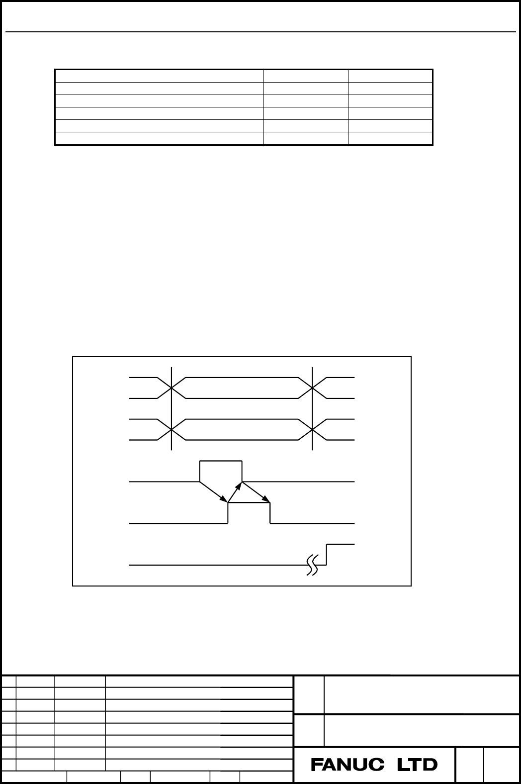
The basic external data input procedure
The basic external data input procedure is described below:
(1) The PMC sets the address signals, EA0 to EA6 that indicate the data type
and data signals ED0 to ED31.
(2) The PMC sets the read signal ESTB to “1”.
(3) When the ESTB signal is set to “1”, the control unit reads the address.
(4) After reading the address, the control unit sets the read completion signal
EREND to “1”.
(5) When the EREND signal is set to “1”, the PMC sets the ESTB signal, to
0.
(6) When the ESTB signal is set to “0”, the control unit sets the EREND
signal to 0.
This completes the data input procedure. New data can now be entered.
The timing diagram is shown below:
EA0~EA6
ED0~ED15
ESTB
EREND
ESEND
Only for external program number search
End of
search
Fig. 1.1(a) Timing diagram of External data input
Contents Summary of Series 30i-MODEL A, External Data Input Additional Manual
- Page 1TECHNICAL REPORT NO. TMN 04/020E Date :Mar .30, 2004 General Manager of Software Laboratory FANUC Series 30i-A Newly additional functions 1. Communicate this report to: Your information only GE Fanuc-N, GE Fanuc-E FANUC Robotics MILACRON Machine tool builder Sales agency End user 2. Summary for Sale
- Page 2FANUC Series30i –A newly additional functions Drawing number Functions 1 A-79227E External Data Input 2 A-79226E One Touch Macro call 3 A-79196E Temporary absolute coordinate setting 4 A-79354E System alarm 5 A-79349E Touch Panel Control 6 A-79253E Distance coded linear scale interface 7 A-79364E Li
- Page 3FANUC Series 30i-MODEL A External Data Input Specifications FANUC Series 30i-MODEL A Title External Data Input Draw A-79227E No. Ed. Date Design Description Page 1/22 Date Jan.09.’04 Design. Apprv.
- Page 4Outlines Overview In the external data input function, the CNC can be operated by the external data which use the signal of PMC. This function is an optional function. There are following functions in the external data input. - External tool offset - External program number search - External work co
- Page 5External tool offset The tool offset value of the offset number which is specified in the part program can be externally modified by the signal of PMC. An input signal can designate whether the input tool offset value is absolute or incremental. When No.0 is selected as the offset number in the lath
- Page 6External alarm message By sending alarm number from PMC, the CNC is brought to an alarm status; an alarm message is sent to the CNC, and the message is displayed on the screen of the CNC. Reset of alarm status is also done with external data. Up to 4 alarm numbers and messages can be sent at a same
- Page 7Explanation for connection The following signals are used to send data from the PMC to the CNC. Signal name Input signal Output signal Address signal for external data input EA0 to EA6 Data signal for external data input ED0 to ED31 Read signal for external data input ESTB Read completion signal for
- Page 8No. Item E E E E E E E E ED31~ED16 ED15~ED0 S A A A A A A A T 6 5 4 3 2 1 0 B 1 External program 1 0 0 0 X X X X Program number (BCD 4 digits with unsign) number 2 External tool offset 1 0 0 1 X X X X Offset value (BCD 8 digits with sign *1) 3 External workpiece 1 0 1 0 axis code Shift value (BCD 8
- Page 9Axis code Axis EA3 EA2 EA1 EA0 1st axis 0 0 0 0 2nd axis 0 0 0 1 3rd axis 0 0 1 0 4th axis 0 0 1 1 5th axis 0 1 0 0 6th axis 0 1 0 1 7th axis 0 1 1 0 8th axis 0 1 1 1 9th axis 1 0 0 0 10th axis 1 0 0 1 11th axis 1 0 1 0 12th axis 1 0 1 1 13th axis 1 1 0 0 14th axis 1 1 0 1 15th axis 1 1 1 0 16th axi
- Page 10The controller checks the state of the RST (NC reset) signal for a reset input between the rising edge of the ESTB signal (read signal for external data input) and the start of the search. Concretely, the controller cancels the external program number search if the RST (NC reset) signal becomes 1 ev
- Page 11NOTE 1 The external program number search is available when parameter ESR(No.6300#4) is set to “1”. 2 In reset state the automatic operation lamp is off. If the start button is pushed in the cycle operation stop or hold state, search execution starts from the actual position indicated by the pointer
- Page 12Read signal for external data 2nd command input (ESTB) Read completion signal for Search command is kept. external data input (EREND) Search completion signal for external data input (ESEND) 2nd program Cycle start signal search (ST) Cycle start lamp signal (STL) Automatic operation signal (OP) 2nd
- Page 13External Tool offset These signals provide for changing the tool compensation value via the PMC. When the offset number is specified by a part program, data input from the PMC is added to the offset value. The offset value can also be used as input data itself by specifying the input signal. When th
- Page 14Data specification for external tool offset (For milling machine) Address Data *1 E E E E E E E E E E E A A A A A A A D D … D D 6 5 4 3 2 1 0 31 30 1 0 0 0 1 a/i g/w 0 r/l Sign Offset value 0: + Specified by BCD 8-digit code 1: - (0 to +/- 79999999) *1 0 Incremental specification (Input value is add
- Page 15Data specification for external tool offset (For the lathe turning machine) Address Data *1 E E E E E E E E E E E A A A A A A A D D … D D 6 5 4 3 2 1 0 31 30 1 0 0 0 1 a/i g/w Sign X/Z/R Offset value 0: + Specified by BCD 8-digit code 1: - (0 to +/- 79999999) *1 Incremental specification 0 (Input va
- Page 16External workpiece coordinate system shift In the external workpiece coordinate system shift, the shift value can be externally modified by the signal of PMC. Each axis has this shift value (parameter No. 1220), and this shift value is added to all the workpiece coordinate systems in common. The shi
- Page 17External alarm message By sending alarm number from PMC, the CNC is brought to an alarm status; an alarm message is sent to the CNC, and the message is displayed on the screen of the CNC. Reset of alarm status is also done with external data. Up to 4 alarm numbers and messages can be sent at a same
- Page 18Data specification method in external message Item E E E E E E E ED15~ED0(binary) A A A A A A A 6 5 4 3 2 1 0 Alarm set 1 0 0 0 0 0 0 Alarm No. Alarm clear 1 0 0 0 0 0 1 Alarm No. Operator message list 1 0 0 0 1 0 0 Message No. Operator message 1 0 0 0 1 0 1 Message No. clear Message 1 0 0 0 X 1 1 C
- Page 19Substitution of the number of required parts and number of machined parts Substitution is possible for the number of parts required and the number of parts machined. Data specification for No. of parts required and No. of parts machined. Address Data E E E E E E E E E A A A A A A A D ........... D 6
- Page 20Signals Address signals for external data input EA0 to EA6
[Classification] Input signal [Function] These signals indicate the type of the entered data. Data signals for external data input ED0 to ED31 - Page 21Parameter #7 #6 #5 #4 #3 #2 #1 #0 6300 EEX ESR ESC [Input type] Parameter input [Data type] Bit path #3 ESC When a reset is input between input of the external data input read signal ESTB and execution of a search, the external program number search function: 0 : Performs a search. 1 : Does not perf
- Page 22#1 EXM This bit selects an external operator message specification. 0 : A message number from 0 to 999 can be sent. The message of a message number from 0 to 99 is displayed together with its number. The CNC adds 2000 to a number for distinction. A message number from 100 to 999 is not displayed on
- Page 236310 Setting for number addition to external operator messages [Input type] Parameter input [Data type] Word machine group [Unit of data] [Valid data range] 0 to 4095 This parameter sets the number of messages to which message numbers are to be prefixed in external operator message display. When 0 i
- Page 24Alarm and message Number Message Description DS059 SPECIFIED NUMBER NOT The No. specified for a program No. or sequence No. search FOUND could not be found. There was an I/O request issued for a pot No. or offset (tool data), but either no tool numbers have been input since power ON or there is no d