PWM Distribution Module, DESCRIPTIONS Additional Manual Page 10
Additional Manual
DRAW.
No.
TITLE
Pa
g
e
010
/
24
DESCRIPTIONDESIGNDATE EDIT
PWM Distribution Module
DESCRIPTIONS
A-72562E-029
FANUC LTD
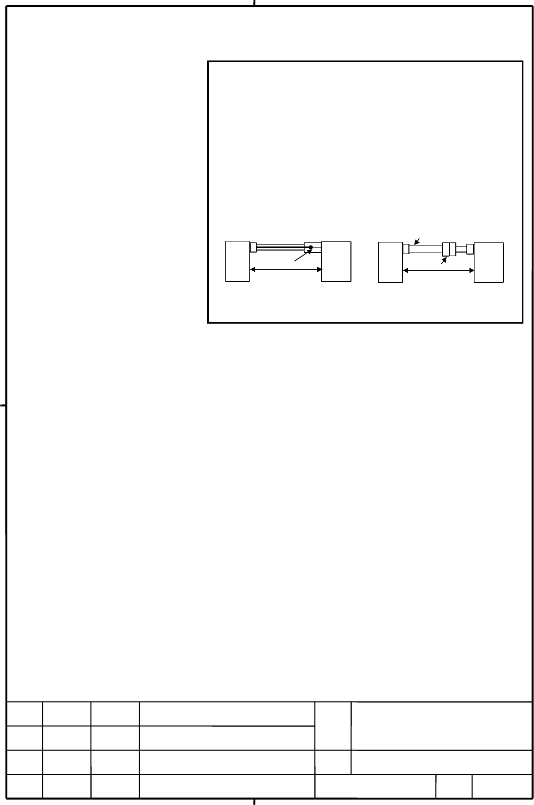
NOTE
1 The ground plate to which the shield is connected must be placed as
close as possible to the PWM Distribution Module so that distance
between the ground plate and the PWM Distribution Module becomes
shortest.
2 In case that the cable is prepared by MTB, total resistance of 5V and
0V must be less than 2 ohm
.
3 Pulsecoder side connector can accept maximum 0.5mm
2
(wire
construction 20/0.18 or 104/0.08, diameter φ1.5 or less) wire and
sheath diameter is
φ5.7 to φ8.0. In case of using thicker wire or
cable, take measures described below.
The total resistance (Round
trip) of 5 V and 0 V must be
less than 2
Ω
.
[Case 1] Cable conductor exceeds 0.5mm
2
. [Case 2] Sheath diameter of exceeds
φ
8.
Soldering or crimping
Servo motor
PDM
Connector
Cable thicker than
φ
8
PDM
Servo motor
The total resistance (Round
trip) of 5 V and 0 V must be
less than 2
Ω
.
4 In case of incremental Pulsecoder, 6V is not necessary to be
connected.
• Crimp tool specification
A06B-6114-K201/JN1S : For 0.3 mm
2
A06B-6114-K201/JN1L : For 0.18 mm
2
or 0.5 mm
2
•
Connector kit specification
A06B-6114-K204/S : Straight plug (including a contact)
A06B-6114-K204/E : Elbow plug (including a contact)
• Recommended cable
A66L-0001-0460 : Flexible cable 28m or less long
A66L-0001-0462 : Flexible cable 50m or less long
A66L-0001-0481 : Fixed cable 28m or less long
A66L-0001-0491 : Fixed cable 50m or less long
Contents Summary of PWM Distribution Module, DESCRIPTIONS Additional Manual
- Page 1PWM DISTRIBUTION MODULE DESCRIPTIONS 1.Type of applied technical documents Name PWM DISTRIBUTION MODULE DESCRIPTIONS Spec.No./Ver. A-72562E-029 2.Summary of change Group Name / Outline New,Add Applicable Correct,Del Date Basic Function PWM DISTRIBUTION MODULE Add 25-Aug-2004 DESCRIPTIONS Optional Fu
- Page 2PWM DISTRIBUTION MODULE DESCRIPTIONS CONTENTS 1. GENERAL 2. APPLICATIONS 3. ORDERING INFORMATION 4. SPECIFICATIONS 5. HEAT DISSIPATION 6. SLAVE NUMBER SETTING 7. OVERALL CONNECTION DIAGRAM 8. DETAILD CONNECTION OF CABLES 8.1. Detailed description of the connection of cable K1 8.2. Detailed descripti
- Page 31. GENERAL The document describes about the PWM Distribution Module (PDM). The PDM has the following main functions. The plural servo amplifiers on the local FSSB include PDM are treated as a single axis amplifier by CNC. (1) The single PWM command from CNC is distributed to the plural servo amplifi
- Page 42. APPLICIATIONS DSA, Series 16i -MODEL B, CNC Series 18i -MODEL B, Series 21i -MODEL B, Power Mate i-MODEL D, Power Mate i-MODEL H CNC software Please ask separately. (Note) SERVO software 90B2(DSA), 90B1(others) CONTROL HRV2 FSSB slave number 4 / FSSB Applied slave αi series servo amplifier α(HV)i
- Page 53. ORDAERING INFORMATON 3.1. PWM DISTRIBUTION MODULE (PDM) Category Name Ordering number Remarks Standard PWM DISTRIBUTON MODULE A06B-6135-H001 0.3kg 3.2. Connectors Category Ordering Manufacturer Part number Q’TY Remarks number Standard A06B-6078-K225 Hirose Electric FI40B-2015S connector 1 For pul
- Page 66. SLAVE NUMBER SETTING Set the rotary switch SW1 according to the slave number of the local FSSB. The function of the rotary switch SW1 is as follows. SW1 setting 0 1 2 3 4 5 6 7 8 9 A B C D E F Local FSSB - - - 4 - - - - - - - - - - - Slave number Note) The available slave number setting of PWM Di
- Page 77. OVERALL CONNECTION DIAGRAM POWER SUPPLY DC24V PWM Distribution Module K1 CP11A K3 CX5X BATTERY CNC K2 BIG SERVO MOTOR COP10B JF1 FEED BACK COP10A COP10L COP10B COP10B MAIN SERVO AMP SERVO AMP FSSB LOCAL COP10A COP10A FSSB COP10B COP10B SERVO AMP SERVO AMP COP10A COP10A PWM Distribution Module TIT
- Page 88. DETAILED CONNECTION OF CABLES 8.1. Detailed description of the connection of cable K1 Power to the PWM Distribution Module should be supplied from an external 24V DC power supply. Cable K1 is necessary to supply DC24V for PWM Distribution Module. PWM Distribution Module External Power supply CP11
- Page 98.2. Detailed description of the connection of cable K2 For servo motor αi, αis, α(HV)i, α(HV)is series The cable K2 is used to connect the PWM Distribution Module and Pulsecoder. Shield PWM Servo motor Distribution (5) RD (6) Module (6) *RD (5) (9, 20) 5V (8, 9) (12, 14) 0V (7, 10) (7) 6V (4) (16)
- Page 10NOTE 1 The ground plate to which the shield is connected must be placed as close as possible to the PWM Distribution Module so that distance between the ground plate and the PWM Distribution Module becomes shortest. 2 In case that the cable is prepared by MTB, total resistance of 5V and 0V must be l
- Page 118.3. Detailed description of the connection of cable K3 [Connection method 1] Incorporating built-in batteries in PWM Distribution Module Battery Battery holder Connect to CX5X PWM Distribution Module NOTE 1. Using the built-in battery (A06B-6135-K001) requires the battery holder (A06B-6135-K002). 2
- Page 12[Connection method 2] Supplying power from one battery unit to more than one PWM Distribution Module Battery case A06B-6050-K060 PDM Battery A06B-6050-K061 CX5X Connector A06B-6093-K303 - A battery case (A06B-6050-K060) and four R20 alkaline batteries (A06B-6050-K061) are available as options. Comme
- Page 139. INSTALLATION 9.1. Note on installation (1) Use a PWM Distribution Module in a completely enclosed cabinet. (2) Install a PWM Distribution Module on a vertical surface, and provide a space of 100mm above and blow the module. Below a PWM Distribution Module, do not place equipment that generates a
- Page 149.3. Connector locations Names Display Remarks 1 Input connector for 24V DC CP11A See the item “8.1” 2 Output connector for 24V DC CP11B See the item “8.1” 3 Rotary switch for slave number setting SW1 See the item “6” 4 Battery connector for absolute Pulsecoder CX5X See the item “8.3” 5 Status LED S
- Page 159.4. Panel cut-out diagrams (In case of installation using screws) PWM Distribution Module TITLE DESCRIPTIONS DRAW. A-72562E-029 No. EDIT DATE DESIGN DESCRIPTION FANUC LTD Page 015/24
- Page 169.5. Maintenance area drawing CAUTION To install/remove the module, a screwdriver must be inserted obliquely. So, sufficient access clearances are required on both sides of the module. As a guideline, if the front of an adjacent module appears flush with the module or slightly set back, allow a clea
- Page 179.6. Installing the module on the DIN rail (In case of using DIN rail) Installing the module on the DIN rail Removing the module from the DIN rail Installing the module 1. Hook the module on the top of the DIN rail 2. Push the module in until it clicks. Removing the module 1. Push down the lock by u
- Page 189.7. Ground Secure the ground line to the ground terminal (GND1) for signals of a PWM Distribution Module, which is located at the bottom of the module, with M3 screw as shown in the figure below. Connect the ground line to the ground plate of the cabinet. Signal ground terminal Ground cable 2mm2 or
- Page 1910.FUNCTION 10.1. Parameter Setting (1) Series and editions of applicable servo software CNC Series and editions of servo software Except DSA 90B1 series / the A (01) version or subsequent ones DSA 90B2 series / the A (01) version or subsequent ones (2) Parameter setting for high-speed HRV current c
- Page 20(3) Parameter setting for 16 pole servo motor Please set up the parameter for the following 16 pole servo motors about the axis which uses the following servo motor. Motor Model Ordering number α2000/2000HVis A06B-0091-B010 α3000/2000HVis A06B-0092-B010 #7 #6 #5 #4 #3 #2 #1 #0 2608(FS15i) P16 2220(F
- Page 2110.2.Status indication The status of PWM Distribution Module (PDM) is indicated on the 7-segmaent LED display. LED Status Description indication - Not Ready PDM is not ready. 0 Ready PDM is ready. # Alarm Indicate the alarm number. (# : 1 to 9, A, b) See the item “10.3 Alarms” NOTE 1. PDM performs a
- Page 2210.3. Alarms The PWM Distribution Module (PDM) has the following error detect functions. Display LED Alarm massage Description number indication (Cause and troubleshooting) 624 1 PDM UNBALANCE ALARM (S1) The value of the current feedback which 625 2 PDM UNBALANCE ALARM (S2) returned from the servo a
- Page 2310.4. Alarm message of servo amplifier When alarm occurs with the servo amplifier connected to PDM via local FSSB, the following two messages of (1) and (2) are at the same time displayed on the message screen of CNC. (1) Alarm message The message shows the contents of alarm. About the details of an
- Page 24You can check what alarm has occurred with which servo amplifier among the servo amplifiers connected to PDM from the contents of a message of above-mentioned (1)(2). NOTE 1. The slave number of local FSSB is counted from the direction near PDM in order of connection of local FSSB. 2. When the CNC s