30i/300i/300is-A, 31i/310i/310is-A & A5, 32i/320i/320is-A Connection manual (Hardware) Page 179
Connection manual (Hardware)
B-63943EN/02 8.CONNECTION TO FANUC I/O Link
- 161 -
NOTE
Be careful not bend optical cables to a radius of 25
mm or less. Be extremely careful not to twist
them.
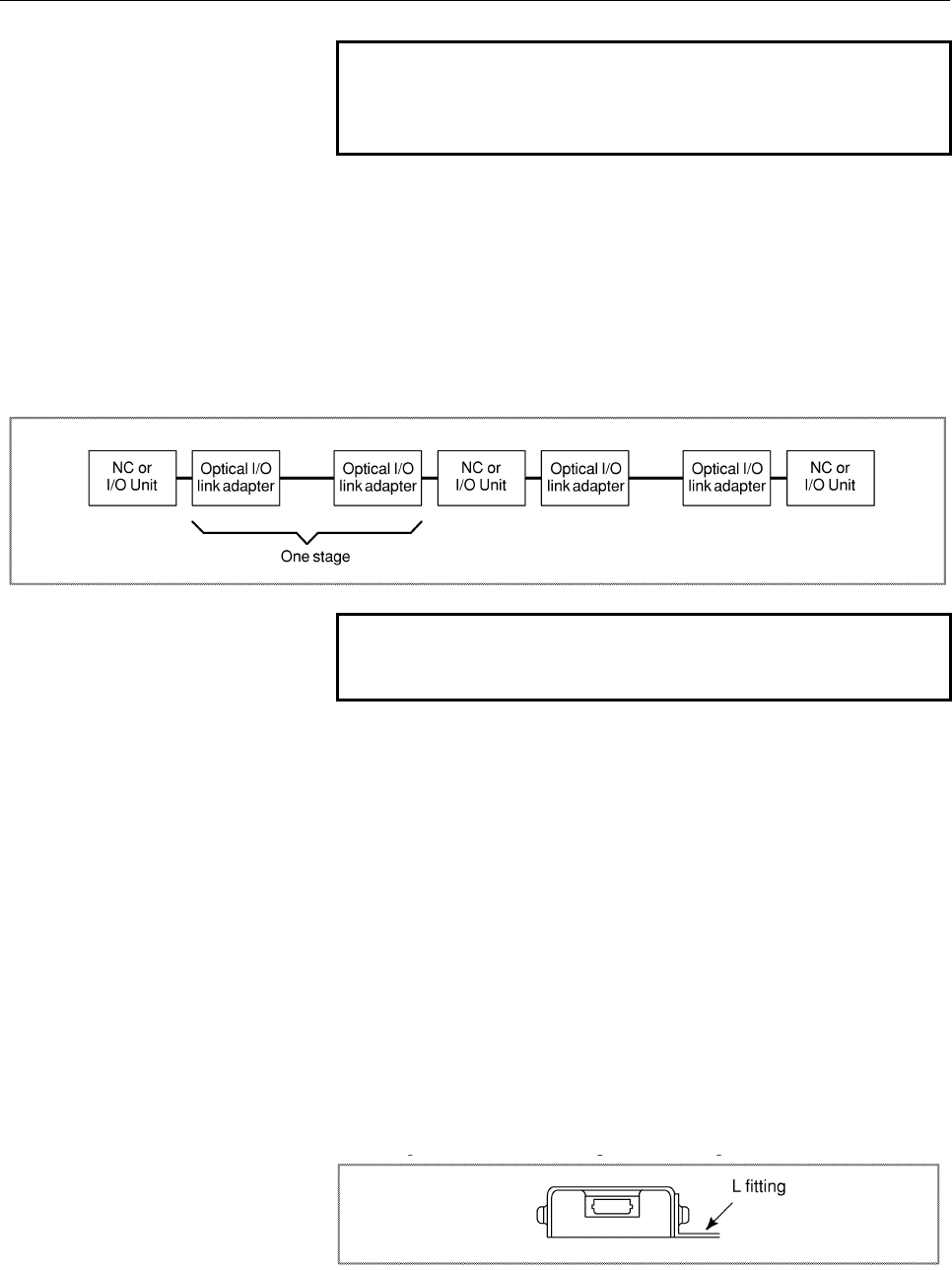
• Maximum number of connectable stages
Up to 16 high-speed type I/O link adapter stages can be
connected in one I/O link, while only up to five conventional I/O
link adapters (standard type) can be connected.
1) Standard type (A13B-0154-B001)
... up to 5 adapter stages can be connected in series
2) Standard type (A13B-0154-B002)
... up to 16 adapter stages can be connected in series
NOTE
It is impossible to use both high-speed and
standard type adapters on the same line.
• Power supply
The same power supply type can be used for both the standard
type (A13B-0154-B001) and high-speed type
(A13B-0154-B002).
(a) Power supply voltage: 4.75 to 5.25 V (at receiving end)
(b) Required current: 200 mA
• Installation conditions
(a) The optical link adapter enclosure is not fully sealed ; install
it with the CNC control unit in the fully enclosed cabinet.
(b) Ground the case using the case fixing screw of the optical
link adapter.
(c) The optical link adapter is light, and it may not be necessary
to mount it with screws. However, keep it from coming in
contact with other circuits to prevent possible short-circuits.
When mounting the optical link adapter in a cabinet, attach
it with an L-type fitting using the case fixing screws (M3)
of the optical link adapter.
Contents Summary of 30i/300i/300is-A, 31i/310i/310is-A & A5, 32i/320i/320is-A Connection manual (Hardware)
- Page 1FANUC Series 30*/300*/300*s-MODEL A FANUC Series 31*/310*/310*s-MODEL A5 FANUC Series 31*/310*/310*s-MODEL A FANUC Series 32*/320*/320*s-MODEL A CONNECTION MANUAL (HARDWARE) B-63943EN/02
- Page 2• No part of this manual may be reproduced in any form. • All specifications and designs are subject to change without notice. The export of this product is subject to the authorization of the government of the country from where the product is exported. In this manual we have tried as much as possi
- Page 3B-63943EN/02 DEFINITION OF WARNING, CAUTION, AND NOTE DEFINITION OF WARNING, CAUTION, AND NOTE This manual includes safety precautions for protecting the user and preventing damage to the machine. Precautions are classified into Warning and Caution according to their bearing on safety. Also, supplem
- Page 4
- Page 5B-63943EN/02 PREFACE PREFACE This manual describes the electrical and structural specifications required for connecting the CNC control unit to a machine tool. The manual outlines the components commonly used for FANUC CNC control units, as shown in the configuration diagram in Chapter 2, and suppli
- Page 6PREFACE B-63943EN/02 Organization of this manuals This manual consists of chapters 1 to 13 and appendixes at the end of the book. Chapter and title Contents Chapter 1 Provides general information related to the connection of the 30i series, as well as CONFIGURATION an introduction to detailed inform
- Page 7B-63943EN/02 PREFACE Related manuals of Series 30i/300i/300is- MODEL A Series 31i/310i/310is- MODEL A Series 31i/310i/310is- MODEL A5 Series 32i/320i/320is- MODEL A The following table lists the manuals related to Series 30i/300i /300is-A, Series 31i/310i /310is-A, Series 31i/310i /310is-A5, Series
- Page 8PREFACE B-63943EN/02 Related manuals of SERVO MOTOR αis/αi/βis/βi series The following table lists the manuals related to SERVO MOTOR αis/αi/βis/βi series Table 2 Related manuals Specification Manual name number FANUC AC SERVO MOTOR αis series FANUC AC SERVO MOTOR αi series B-65262EN DESCRIPTIONS FA
- Page 9B-63943EN/02 TABLE OF CONTENTS TABLE OF CONTENTS DEFINITION OF WARNING, CAUTION, AND NOTE .................................s-1 PREFACE ....................................................................................................p-1 1 CONFIGURATION .............................................
- Page 10TABLE OF CONTENTS B-63943EN/02 3.7 CABLING DIAGRAM ................................................................................... 46 3.8 DUSTPROOF MEASURES FOR CABINETS AND PENDANT BOXES ...... 47 4 POWER SUPPLY CONNECTION......................................................... 48 4.1 GENERAL
- Page 11B-63943EN/02 TABLE OF CONTENTS 5.5 Linking The EMBEDDED Ethernet Interface ............................................... 96 5.5.1 Connection to the Ethernet Interface......................................................................96 5.5.2 Specification of Twisted-Pair Cable..................
- Page 12TABLE OF CONTENTS B-63943EN/02 7.3.9 Installation ............................................................................................................150 7.3.10 Notes on Installing an Analog Input Separate Detector Interface Unit ................152 8 CONNECTION TO FANUC I/O Link ...........
- Page 13B-63943EN/02 TABLE OF CONTENTS 8.5.6 DO (Output Signal) Connection...........................................................................212 8.5.7 Manual Pulse Generator Connection....................................................................215 8.5.8 External View.........................
- Page 14TABLE OF CONTENTS B-63943EN/02 8.9.4 I/O Address...........................................................................................................262 8.9.4.1 Keyboard of main panel................................................................................... 262 8.9.4.2 Override signal
- Page 15B-63943EN/02 TABLE OF CONTENTS 11.2.3 Power Supply Capacity ........................................................................................294 11.3 CONNECTION TO CNC PERIPHERALS .................................................. 295 11.3.1 Main Power Input...................................
- Page 16TABLE OF CONTENTS B-63943EN/02 13.5.2.3 QWERTY MDI used in cases other than combination (2) .............................. 334 13.5.3 Ground Terminal Connection of Units.................................................................335 13.6 PERIPHERAL EQUIPMENT AND CONNECTION .....................
- Page 17B-63943EN/02 TABLE OF CONTENTS B.3 RECOMMENDED CONNECTORS, APPLICABLE HOUSINGS, AND CABLES .................................................................................................... 443 B.3.1 Recommended Connectors............................................................................
- Page 18
- Page 19B-63943EN/02 1.CONFIGURATION 1 CONFIGURATION -1-
- Page 201.CONFIGURATION B-63943EN/02 1.1 CONTROL UNIT CONFIGURATION AND COMPONENT NAMES The 30i series control units are divided into two types: the LCD-mounted type and stand-alone type. LCD-mounted type control units have a built-in display. Stand-alone type control units have a separate display unit. In
- Page 21B-63943EN/02 1.CONFIGURATION LCD-mounted type control unit Vertical soft keys Liquid-crystal display Memory card interface USB port Horizontal soft keys NOTE 1 This figure is a front view of the LCD-mounted type control unit with an 10.4” TFT color liquid-crystal display. The configurations of other
- Page 221.CONFIGURATION B-63943EN/02 LCD-mounted type control unit Fan unit Battery Unit rear panel Servo unit connector [COP10A-1] [COP10A-2] (7) Ethernet Power supply connector module [CD38A] (5.5) MDI connector Fuse Power supply [CA55] (5.1) connector [CPD16A] Soft key Serial spindle connector [JA41] (6.
- Page 23B-63943EN/02 1.CONFIGURATION 1.1.2 Configurations of Stand-alone Type Control Units Stand-alone type Series 30i/31i/32i control units (A circle indicates that the corresponding unit is available.) Expansion Slot rack name 30i 31i 32i slot 2-slot rack 2 4-slot rack 4 Series 30i/31i/32i display units
- Page 241.CONFIGURATION B-63943EN/02 Stand-alone type control unit Battery connector I/O device interface Battery connector I/O device interface I/O Link connector connector High-speed skip connector Memory card interface Serial spindle connector Ethernet LED Ethernet connector LED for blown fuse check 24-V
- Page 25B-63943EN/02 1.CONFIGURATION 10.4” LCD unit for the stand-alone type Series 30i/31i/32i control unit Liquid-crystal display Memory card interface Soft keys MDI connector [CA55] (5.1) Soft key connectors Power supply Touch panel connector connectors [CP1A] [CP1B] (5.2) Optical connector for display c
- Page 261.CONFIGURATION B-63943EN/02 15” LCD unit for the stand-alone type Series 30i/31i/32i control unit Liquid-crystal display Memory card interface Soft keys Fan motor Fan motor MDI connector [CA55] (5.1) Rear view Soft key connectors Power supply Optical connector for connector display control [CPD18]
- Page 27B-63943EN/02 1.CONFIGURATION 1.1.3 Configurations of Optional Boards Additional axis board For I/O-Link [JD1A] (8.2) For servo unit [COP10A] (7) Additional spindle board For serial spindle [JA41L] (6.1) Fast data server board For Ethernet [CD38R] (5.5) HSSB board HSSB optical connector [COP21N] NOTE
- Page 281.CONFIGURATION B-63943EN/02 Profibus master board For Profibus [CN1] Profibus slave board For Profibus [CN2] DeviceNet board For DeviceNet [TBL] FL-net board For FL-net [CD38N] NOTE The numbers in parentheses () in the figures are keyed to the item numbers of the descriptions in this manual. The nu
- Page 29B-63943EN/02 1.CONFIGURATION 1.2 HARDWARE OVERVIEW 1.2.1 LCD-mounted Type Control Unit Overview Main board - CPU for controlling CNC - Power supply - 2-axis to 24-axis control - Spindle interface - LCD/MDI interface - I/O Link - PMC control function - High-speed DI - RS-232C - Memory card interface
- Page 301.CONFIGURATION B-63943EN/02 1.2.2 Stand-alone Type Control Unit Overview 4 slot rack 2 slot rack Main board Slot 3 Slot 1 Slot 4 Slot 2 Options (Slot 1 to 4) Basic system Data server board Main board Data server function - CPU for controlling CNC - Power supply Additional axis board - 2-axis to 24-
- Page 31B-63943EN/02 2.TOTAL CONNECTION DIAGRAMS 2 TOTAL CONNECTION DIAGRAMS - 13 -
- Page 322.TOTAL CONNECTION DIAGRAMS B-63943EN/02 LCD-mounted type control unit LCD display unit Main board 24V-IN(CPD16A) 24 VDC power supply MDI UNIT MDI(CA55) CK27 R232-1(JD56A) RS-232-C I/O unit 5th and 6th serial spindles R232-2(JD36A) RS-232-C I/O unit Touch panel HDI(JA40) High-peed skip input Distrib
- Page 33B-63943EN/02 2.TOTAL CONNECTION DIAGRAMS Stand-alone type control unit Main board Slot 1 24V-IN(CPD19A) 24 VDC power supply 24V-OUT(CPD19B) To I/O device Optical fiber ccable LCD UNIT MDI UNIT COP21A,B,M DISPLAY(COP21A) 24VDC CP1A CA55 CK27 CP1B Memory card (Touch panel) PANEL i or personal computer
- Page 342.TOTAL CONNECTION DIAGRAMS B-63943EN/02 When optional functions are provided Additional spindle board Optional slot SPDL(JA41L) PSM Position coder 7th spindle SPM Additional axis board To 8th spindle FSSB(COP10A-3) COP10B SVM Servo motor COP10A COP10B SVM Servo motor COP10A COP10B SVM Servo motor C
- Page 35B-63943EN/02 2.TOTAL CONNECTION DIAGRAMS When optional functions are provided Fast data server Optional slot board ATA card The user should provide an ATA card. ETHERNET(CD38R) Ethernet HSSB ボード HSSB(COP21N) Personal Computer or PANEL i (Note 1) Profibus master board PROFI(CN1) Another NC (another P
- Page 363.INSTALLATION B-63943EN/02 3 INSTALLATION - 18 -
- Page 37B-63943EN/02 3.INSTALLATION 3.1 ENVIRONMENTAL REQUIREMENTS OUTSIDE THE CABINET 3.1.1 Environmental Conditions outside the Cabinet The peripheral units and the control unit have been designed on the assumption that they are housed in closed cabinets. In this manual "cabinet" refers to the following:
- Page 383.INSTALLATION B-63943EN/02 3.1.2 Installation Conditions of the CNC and Servo Unit in the Cabinet LCD-mounted type control unit Stand-alone type Condition and display unit control unit Operating 0°C to 58°C 0°C to 55°C Storage, Ambient −20°C to 60°C Transport temperature Temperature 0.3°C/minute or
- Page 39B-63943EN/02 3.INSTALLATION 3.2 POWER SUPPLY CAPACITY 3.2.1 Power Supply Capacities of CNC-related Units The following CNC-related units require an input power supply that satisfies the indicated current capacities with a power supply voltage of 24 VDC ±10%. Here, note that momentary voltage changes
- Page 403.INSTALLATION B-63943EN/02 Table 3.2.1 (b) Power supply rating (peripheral units) Power supply Unit Remarks capacity MDI unit 0A Standard machine operator’s panel 0.4A Operator's panel I/O module 0.3A+7.3mA×DI Connector panel I/O module (basic) 0.2A+7.3mA×DI Connector panel I/O module 0.1A+7.3mA×DI
- Page 41B-63943EN/02 3.INSTALLATION 3.3 DESIGN AND INSTALLATION CONDITIONS OF THE MACHINE TOOL MAGNETIC CABINET When a cabinet is designed, it must satisfy the environmental conditions described in Section 3.1. In addition, the magnetic interference on the screen, noise resistance, and maintenance requireme
- Page 423.INSTALLATION B-63943EN/02 To obtain good ventilation in the module, the I/O unit and connector panel I/O module must be installed in the direction shown in the following figure. Clearances of 100 mm or more both above and below the I/O unit are required for wiring and ventilation. Equipment radiat
- Page 43B-63943EN/02 3.INSTALLATION 3.4 THERMAL DESIGN OF THE MACHINE TOOL MAGNETIC CABINET The internal air temperature of the cabinet increases when the units and parts installed in the cabinet generate heat. Since the generated heat is radiated from the surface of the cabinet, the temperature of the air
- Page 443.INSTALLATION B-63943EN/02 3.4.2 Heat Output of Each Unit Table 3.4.2 (a) Heat output Heat Unit Remarks output LCD-mounted 7.2”/8.4”/10.4” type display unit 33W (Note) type control unit 15” type display unit 49W (Note) Stand-alone type Control unit (alone) 30W control unit 10.4” display unit 13W 15
- Page 45B-63943EN/02 3.INSTALLATION 3.4.3 Thermal Design of Operator's Panel With a small cabinet like the operator's panel, the heat dissipating capacity of the cabinet is as shown below, assuming that there is sufficient mixing of the air inside the cabinet. Coated metal surfaces: 8 W/m2°C Plastic surface
- Page 463.INSTALLATION B-63943EN/02 In this case, the allowable total heat dissipation for the cabinet is: 8 × 0.5722 × 13 + 3.7 × 0.2632 × 13 = 72 W. In consequence, it can be concluded that the units shown in Table 3.4.3 on the next page can be installed in this cabinet. Table 3.4.3 LCD-mounted type contr
- Page 47B-63943EN/02 3.INSTALLATION 3.5 ACTION AGAINST NOISE The CNC has been steadily reduced in size using surface-mount and custom LSI technologies for electronic components. The CNC also is designed to be protected from external noise. However, it is difficult to measure the level and frequency of noise
- Page 483.INSTALLATION B-63943EN/02 1 The groups must be 10 cm or more apart from one another when binding the cables in each group. 2 The electromagnetic shield refers to shielding between groups with grounded steel plates. 3 The shield is not required when the cable between the CNC and MDI is shorter than
- Page 49B-63943EN/02 3.INSTALLATION 3.5.2 Ground The CNC machine tool uses the following three types of grounding: • Signal grounding Signal grounding supplies a reference potential (0V) for electrical signals. • Grounding for protection Grounding for protection is performed for safety reasons as well as to
- Page 503.INSTALLATION B-63943EN/02 Fig. 3.5.2 (b) Example of grounding with a nearby ground plate Notes on grounding • The ground resistance in protective grounding (PE) must be 100 Ω or less (type D grounding). • The cable used for protective grounding (PE) must be of a sufficient cross section to allow c
- Page 51B-63943EN/02 3.INSTALLATION Table 3.5.2 Guideline for selecting the cross-sectional area of the protection copper cable Rated current of the fuse for protecting Cross-sectional area of the an assumed circuit or the rated current of protection copper cable the overcurrent protection unit mm2 A 30 2 o
- Page 523.INSTALLATION B-63943EN/02 3.5.3 Connecting the Signal Ground (SG) of the Control Unit Connecting the 0 V output in the CNC to a protective circuit (ground) The IEC 204-1 and JIS B 6015 standards specify the following: - Protection against malfunctions due to ground faults “To make the control circ
- Page 53B-63943EN/02 3.INSTALLATION Connecting the ground terminal of an LCD-mounted type control unit Connect the 0-V line in the control unit with the ground plate of the cabinet or a nearby plate via the protective grounding terminal (see above figure). - 35 -
- Page 543.INSTALLATION B-63943EN/02 Connecting the ground terminal of a stand-alone type control unit For 2-slot rack For 4-slot rack Signal ground terminal (Faston terminal) Ground cable 2 2 mm or more Grounding plate of the cabinet PE Connect the 0-V lines of the electronic circuits in the control unit to
- Page 55B-63943EN/02 3.INSTALLATION 3.5.4 Noise Suppressor The AC/DC solenoid and relay are used in the power magnetics cabinet. A high pulse voltage is caused by coil inductance when these devices are turned on or off. This pulse voltage induced through the cable causes the electronic circuits to be distur
- Page 563.INSTALLATION B-63943EN/02 Diode (used for direct-current circuits) Diode Use a diode which can withstand a voltage up DC relay to two times the applied voltage and a current up to two times the applied current. - 38 -
- Page 57B-63943EN/02 3.INSTALLATION 3.5.5 Cable Clamp and Shield Processing If a cable connected to the CNC, servo amplifier, spindle amplifier, or other device requires shielding, clamp the cable as shown below. The clamp both supports and shields the cable. Use this clamp to ensure stable operation of the
- Page 583.INSTALLATION B-63943EN/02 Machine side installation board Control unit Ground plate Metal fittings for clamp Shield cover Fig. 3.5.5 (b) Cable clamp (2) NOTE Bring together the cables connected to a CNC or amplifier near the unit and shield them. Prepare ground plate like the following figure. Gro
- Page 59B-63943EN/02 3.INSTALLATION Ground plate 8 12 20 Fig. 3.5.5 (d) Ground plate holes (Reference) Outer drawings of metal fittings for clamp. Max. 55mm 28mm 6mm 17mm Fig. 3.5.5 (e) Outer drawings of metal fittings for clamp Ordering specification for metal fittings for clamp A02B-0124-K001 (8 pieces) -
- Page 603.INSTALLATION B-63943EN/02 3.5.6 Measures Against Surges due to Lightning To protect the devices from surge voltages due to lightening, it is recommended to install surge-absorbing elements between the lines of the input power and between one line and ground. This does not, however, assure protecti
- Page 61B-63943EN/02 3.INSTALLATION Notes (1) For a better surge absorbing effect, the wiring shown by heavy line must be as short as possible. Wire Size: The wire diameter must be 2 mm2 or greater. Wire length: The sum of the length (a) of the wire for the connection of surge-absorbing element 1 and that (
- Page 623.INSTALLATION B-63943EN/02 3.6 CONTROL UNIT 3.6.1 Installing the LCD-mounted Type Control Unit The control unit has a built-in fan motor. Air enters the control unit through the bottom and is drawn through the fan motor which is located on the top of the control unit. Space A , shown in Fig. 3.6.1,
- Page 63B-63943EN/02 3.INSTALLATION 3.6.2 Installing the Stand-alone Type Control Unit The control unit is equipped with a fan motor. Air is fed into the bottom of the unit and output from the fan motor mounted on the top of the unit. The spaces shown in Fig. 3.6.2 (areas A and B ) are always required to en
- Page 643.INSTALLATION B-63943EN/02 3.7 CABLING DIAGRAM For the cabling diagram, see the control unit configuration and component names in Section 1.1. - 46 -
- Page 65B-63943EN/02 3.INSTALLATION 3.8 DUSTPROOF MEASURES FOR CABINETS AND PENDANT BOXES The cabinet and pendant box that house a display and a operator's panel that are to be designed and manufactured by the machine tool builder are susceptible to dust, cutting debris, oil mist, etc. Note the following an
- Page 664.POWER SUPPLY CONNECTION B-63943EN/02 4 POWER SUPPLY CONNECTION - 48 -
- Page 67B-63943EN/02 4.POWER SUPPLY CONNECTION 4.1 GENERAL This chapter explains the connection of power supply for control unit. - 49 -
- Page 684.POWER SUPPLY CONNECTION B-63943EN/02 4.2 TURNING ON AND OFF THE POWER TO THE CONTROL UNIT 4.2.1 Power Supply for the Control Unit Supply power (24VDC) to the control unit from an external sources. Provide an ON/OFF circuit for turning the AC power on and off outside the unit as shown in Fig. 4.2.1
- Page 69B-63943EN/02 4.POWER SUPPLY CONNECTION 4.2.2 External 24 VDC Power Specification and Circuit Configuration Specifications of recommended external 24 VDC power supply (regulated power supply): (The power supply must satisfy UL1950.) Output voltage: +24 V ±10% (21.6 V to 26.4 V) (including ripple volt
- Page 704.POWER SUPPLY CONNECTION B-63943EN/02 - Notes to take when the vertical axis exists When the vertical axis exists, select the DC power supply that has a long voltage hold time to decrease the amount of vertical axis falling during power-off (including a power failure). If the operating voltage drop
- Page 71B-63943EN/02 4.POWER SUPPLY CONNECTION <2> Circuit examples that exceed the output voltage specifications (21.6 V to 26.4 V) due to an abrupt load change Example 1 Regulated AC input power supply CNC unit Device with remarkable load fluctuations Example 2 Regulated AC input power supply CNC unit Dev
- Page 724.POWER SUPPLY CONNECTION B-63943EN/02 Recommended The following circuit configuration is recommended. The power to the CNC and other units (FANUC I/O Unit MODEL A (I/O Unit-A), FANUC Servo Unit β series with an I/O link (β amplifier with an I/O link), and so on in the sample configuration below) is
- Page 73B-63943EN/02 4.POWER SUPPLY CONNECTION t2:-500ms Means that the power to units (including the Power Mate) is turned on within 500 ms after the power to the CNC is turned on. Turning the power to units off simultaneously when turning the power to the CNC off: This means that the power to units may be
- Page 744.POWER SUPPLY CONNECTION B-63943EN/02 interface unit, stand-alone type LCD unit, control power supply of the servo amplifier, and separate detector (such as a scale). As for a PANEL i, no specific power-off sequence for the CNC control unit is required. CAUTION When the PANEL i is used, the OS must
- Page 75B-63943EN/02 4.POWER SUPPLY CONNECTION 4.3 CABLE FOR POWER SUPPLY TO CONTROL UNIT Supply the power to the control unit from an external 24 VDC power supply. CNC control unit External power CPD16A 1 +24V 24VDC stabilized 2 0V power 3 24VDC ±10% Cable CPD16A AMP Japan 1-178288-3 (housing) 1-175218-5 (
- Page 764.POWER SUPPLY CONNECTION B-63943EN/02 4.4 BATTERIES In a system using this CNC, batteries are used as follows: Use Component connected to battery Memory backup in the CNC control CNC control unit unit BIOS data backup in the PANEL i PANEL i Preservation of the current position Separate detector int
- Page 77B-63943EN/02 4.POWER SUPPLY CONNECTION 4.4.1.1 Replacing the lithium battery Replacing battery for LCD-mounted type control unit - Replacement procedure When a lithium battery is used Prepare a new lithium battery (ordering code: A02B-0200-K102 (FANUC specification: A98L-0031-0012)). 1 Turn on the p
- Page 784.POWER SUPPLY CONNECTION B-63943EN/02 Battery case Connector Lithium battery A02B-0200-K102 Fig. 4.4.1 (b) Unit with optional slots Battery cable Fig. 4.4.1 (c) Clamping the battery cable WARNING Using other than the recommended battery may result in the battery exploding. Replace the battery only
- Page 79B-63943EN/02 4.POWER SUPPLY CONNECTION Replacing the battery for stand-alone type control unit - Replacing the battery If a lithium battery is used, have A02B-0200-K102 (FANUC internal code: A98L-0031-0012) handy. 1 Turn the CNC on. About 30 seconds later, turn the CNC off. 2 Remove the battery from
- Page 804.POWER SUPPLY CONNECTION B-63943EN/02 Replacing the alkaline dry cells (size D) (1) Prepare two new alkaline dry cells (size D). (2) Leave the power to the CNC turned on for 30 seconds or so. (3) Turn the CNC off. (4) Remove the battery case cover. (5) Replace the batteries, paying careful attentio
- Page 81B-63943EN/02 4.POWER SUPPLY CONNECTION Use of alkaline dry cells (size D) - Connection Power from the external batteries is supplied through the connector to which the lithium battery is connected. The lithium battery, provided as standard, can be replaced with external batteries in the battery case
- Page 824.POWER SUPPLY CONNECTION B-63943EN/02 4.4.2 Batteries for PANEL i (3VDC) A lithium battery is used to back up BIOS data in the CNC display unit with PC functions. This battery is factory-set in the PANEL i. This battery has sufficient capacity to retain BIOS data for one year. If the voltage of a b
- Page 83B-63943EN/02 4.POWER SUPPLY CONNECTION Connector Lithium battery BAT1 A02B-0200-K102 Fig. 4.4.2 Connecting the lithium battery of a PANEL i - 65 -
- Page 844.POWER SUPPLY CONNECTION B-63943EN/02 4.4.3 Battery for Separate Absolute Pulse Coders (6VDC) (1) When the voltage of the battery for absolute pulse coders becomes low, DS alarms 306 to 308 occur. (2) When DS alarm 307 (alarm indicating the voltage of the battery becomes low) occurs, replace the ba
- Page 85B-63943EN/02 4.POWER SUPPLY CONNECTION Replacing batteries To prevent absolute position information in absolute pulse coders from being lost, turn on the machine power before replacing the battery. The replacement procedure is described below. (Note: The turning-on step is not required when the αi o
- Page 864.POWER SUPPLY CONNECTION B-63943EN/02 Replacing D-size alkaline dry cells in the battery case Replace four D-size alkaline batteries (A06B-6050-K061) in the battery case installed in the machine. (1) Have four D-size alkaline batteries on hand. (2) Loosen the screws on the battery case. Remove the
- Page 87B-63943EN/02 5.CONNECTION TO CNC PERIPHERALS 5 CONNECTION TO CNC PERIPHERALS - 69 -
- Page 885.CONNECTION TO CNC PERIPHERALS B-63943EN/02 5.1 CONNECTION WITH THE DISPLAY/MDI UNIT (LCD- MOUNTED TYPE 30i SERIES) 5.1.1 Overview Since the controller and display unit of the LCD-mounted type 30i series are connected internally, they do not need to be connected externally. Therefore, this section
- Page 89B-63943EN/02 5.CONNECTION TO CNC PERIPHERALS 5.1.3 Connection with the Standard MDI Unit CK27 , Maximum cable length : 20m) NOTE For MDI cable connector mating on the CA55 side, a simple lock mechanism is employed. Ensure that a load greater than 1 kg is not applied to the connectors. Moreover, clam
- Page 905.CONNECTION TO CNC PERIPHERALS B-63943EN/02 5.1.4 Key Layout of MDI For Lathe (T series) - Standard MDI unit (ONG keys) Help key Reset key Address/numeric keys Edit keys Cancel (CAN) key Case shift key Shift key Input key AUX key CTRL key ALT key TAB key Page change keys Cursor keys Function keys -
- Page 91B-63943EN/02 5.CONNECTION TO CNC PERIPHERALS For Machining center (M series) - Standard MDI unit (ONG keys) Help key Reset key Address/numeric keys Edit keys Cancel (CAN) key Case shift key Shift key Input key AUX key CTRL key ALT key TAB key Page change keys Cursor keys Function keys - Small MDI un
- Page 925.CONNECTION TO CNC PERIPHERALS B-63943EN/02 Common to lathe system / machining center system - Standard MDI unit (QWERTY keys) Help key Function keys Reset key Address keys Numeric keys Case shift key AUX key CTRL key Shift key ALT key Input key TAB key Page change keys Cursor keys Edit keys Cancel
- Page 93B-63943EN/02 5.CONNECTION TO CNC PERIPHERALS 5.2 CONNECTION WITH THE DISPLAY/MDI UNIT (STAND-ALONE TYPE 30i SERIES) 5.2.1 Overview This subsection explains connection with the display/MDI units for the stand-alone type Series 30i/31i/32i. For the stand-alone type Series 300i/310i/320i, see Chapter 1
- Page 945.CONNECTION TO CNC PERIPHERALS B-63943EN/02 Connection of a power supply to the LCD unit An optical fiber cable is used to make the connection between the CNC control unit and LCD unit. For details of the optical fiber cable, see Appendix D. Supply the power to the LCD unit from an external 24 VDC
- Page 95B-63943EN/02 5.CONNECTION TO CNC PERIPHERALS Connection between the LCD unit and MDI unit For the connection between the connector (CA55) of the LCD unit and that (CK1) of the MDI unit, see Subsection 5.1.3, “Connection with the Standard MDI Unit.” With the LCD-mounted type Series 30i/31i/32i, the c
- Page 965.CONNECTION TO CNC PERIPHERALS B-63943EN/02 5.3 CONNECTION WITH INPUT/OUTPUT DEVICES 5.3.1 Overview An input/output device is used to enter information such as CNC programs and parameters from an external device to the CNC, or to output information from the CNC to an external device. The input/outp
- Page 97B-63943EN/02 5.CONNECTION TO CNC PERIPHERALS 5.3.2 Connecting I/O Devices Unit rear panel R232-1 R232-2 Punch panel JD56A JD36A Handy File This figure shows an example of connection for the LCD-mounted type 30i series. - 79 -
- Page 985.CONNECTION TO CNC PERIPHERALS B-63943EN/02 NOTE This interface is the RS-232C interface on the CNC side. When using the PANEL i, usually use the RS-232C interface on the personal computer for parameter I/Os, program I/Os, and other similar operations. This RS-232C interface on the CNC side can be
- Page 99B-63943EN/02 5.CONNECTION TO CNC PERIPHERALS 5.3.3 RS-232-C Serial Port CNC RELAY CONNECTOR JD36A, JD56A, JD54 (DBM-25S) PCR-E20MDK-SL-A (PCR-EV20MDT) 1 FG 14 2 SD 1 RD 11 SD 15 3 RD 2 0V 12 0V 16 >„ >„ < 4 RS 3 DR 13 ER 17 5 CS 4 0V 14 0V 18 6 DR 5 CS 15 RS 19 7 SG 6 0V 16 0V 20 ER 8 CD 7 CD 17 (*)
- Page 1005.CONNECTION TO CNC PERIPHERALS B-63943EN/02 For LCD-mounted type For stand-alone type NOTE 1 Do not connect anything to those pins for which signal names are not indicated. 2 The recommended cable connector FI30-20S (manufactured by Hirose Electric) cannot be used for connectors JD5A and JD5B of th
- Page 101B-63943EN/02 5.CONNECTION TO CNC PERIPHERALS 5.3.4 RS-232-C Interface Specification RS-232-C Interface signals Generally signals as follows are used in RS-232-C interface. CNC Output SD (Send data) Input RD (Receive data) RS (Request to Send) When CS is not used short CS and RS. CS (Enable to send)
- Page 1025.CONNECTION TO CNC PERIPHERALS B-63943EN/02 Signal description of RS-232-C interface Signal RS-232C I/O Description name circuit number SD 103 Output Sending Start bit Stop bits data RD 104 Input Receiving (When ISO code 0 is sent) data RS 105 Output Sending This signal is set to on when NC starts
- Page 103B-63943EN/02 5.CONNECTION TO CNC PERIPHERALS Transmission Method of RS-232-C interface - Start-stop Generally, two transmission methods are available at the serial interface. This CNC use the start-stop method. With this method, start and stop signals are output before and after each data bit. One c
- Page 1045.CONNECTION TO CNC PERIPHERALS B-63943EN/02 Table 5.3.4 ISO code EIA code Meaning Character 8 7 6 5 4 3 2 1 Character 8 7 6 5 4 3 2 1 0 ○ ○ ● 0 ○ ● Numeral 0 1 ○ ○ ○ ● ○ 1 ● ○ Numeral 1 2 ○ ○ ○ ● ○ 2 ● ○ Numeral 2 3 ○ ○ ● ○ ○ 3 ○ ● ○ ○ Numeral 3 4 ○ ○ ○ ● ○ 4 ● ○ Numeral 4 5 ○ ○ ● ○ ○ 5 ○ ● ○ ○ Num
- Page 105B-63943EN/02 5.CONNECTION TO CNC PERIPHERALS NOTE 1 When the external device is equipped with an ISO/EIA converter, the following items must be noted in Table 5.3.4 (a). Control out (Comment field start) Control in (Comment field end) EIA code (....................)) CR o .. .................. Condi
- Page 1065.CONNECTION TO CNC PERIPHERALS B-63943EN/02 Time chart when the NC receives data (Read into memory) (1) NC outputs DC1. (2) The I/O device starts sending data upon receiving DC1. (3) NC sends DC3 when NC processing is delayed. (4) The I/O device stops sending data to NC after receiving DC3. The dev
- Page 107B-63943EN/02 5.CONNECTION TO CNC PERIPHERALS Time chart when the NC send data (Punch out) (1) NC output DC2. (2) NC outputs punch data in succession. (3) When data processing is delayed at the I/O device. (a) Data output stops within two characters including a currently transmitting character when C
- Page 1085.CONNECTION TO CNC PERIPHERALS B-63943EN/02 Connection between RS-232-C interface and external device CNC side I/O device side SD SD RD RD RS RS CS CS ER ER DR DR CD CD SG SG FG FG - 90 -
- Page 109B-63943EN/02 5.CONNECTION TO CNC PERIPHERALS ● Use the connection shown in the figure below when the ER and DR signals are not used for handshaking. CNC side I/O device side SD SD RD RD RS RS CS CS ER ER DR DR CD CD SG SG FG FG he cable for connecting the I/O device to the CNC should be connected as
- Page 1105.CONNECTION TO CNC PERIPHERALS B-63943EN/02 5.3.5 FANUC Handy FILE NOTE 1 Machine tool builder shall furnish relay connector and relay cable. 2 Use a totally shielded cable for the signal cable. Recommended cable specification: A66L-0001-0284#10P 3 Open all terminals other than illustrated. 4 Set s
- Page 111B-63943EN/02 5.CONNECTION TO CNC PERIPHERALS 5.4 CONNECTING THE HIGH-SPEED SKIP (HDI) 5.4.1 Connecting the High-speed Skip (HDI) CNC JA40 PCR-E20MDK-SL-A (RCR-EV20MDT) 1 HDI0 11 HDI1 2 0V 12 0V 3 HDI2 13 HDI3 4 0V 14 0V 5 0V 15 HDI5 6 HDI4 16 0V 7 <> 17 HDI6 8 <> 18 0V 9 <> 19 HDI7 10 0V 20 0V NOTE
- Page 1125.CONNECTION TO CNC PERIPHERALS B-63943EN/02 Cable connections JA40 1 HDI0 2 0V 11 HDI1 12 0V 3 HDI2 4 0V 13 HDI3 14 0V 6 HDI4 5 or 10 0V 15 HDI5 16 0V 17 HDI6 18 0V 19 HDI7 20 0V 7 8 9 10 Shield Ground plate Recommended cable connector: PCR-E20FA (Honda Tsushin Kogyo) FI30-20S (Hirose Electric) FCN
- Page 113B-63943EN/02 5.CONNECTION TO CNC PERIPHERALS 5.4.2 Input Signal Rules for the High-speed Skip (HDI) Circuit configuration CNC DRIVER IiL/IiH FILTER RECEIVER VH/VL SHIELD Absolute maximum rating Input voltage range Vin: -3.6 to +13.6 V Input characteristics Unit Symbol Specification Unit Remark High
- Page 1145.CONNECTION TO CNC PERIPHERALS B-63943EN/02 5.5 Linking The EMBEDDED Ethernet Interface CAUTION Before attaching or removing cables, power off the CNC main unit, and confirm that the power is off. Ask the respective manufacturers for explanations about how to build a network and about conditions fo
- Page 115B-63943EN/02 5.CONNECTION TO CNC PERIPHERALS Some of the units (hub, transceiver, etc.) required to build a network are not dust-proof. Using them in an atmosphere with dust or oil mist may lead to a communication error or failure. They should be enclosed in a dust-proof cabinet. Leading in Ethernet
- Page 1165.CONNECTION TO CNC PERIPHERALS B-63943EN/02 5.5.2 Specification of Twisted-Pair Cable Cable connection The connectors of a cable for connecting between the 10BASE-T/ 100BASE-TX interface (CD38A) and the hub have the pin arrangement shown below. CD38A HUB 1 TX+ 1 TX+ 2 TX- RJ-45 modular jack 2 TX- 3
- Page 117B-63943EN/02 5.CONNECTION TO CNC PERIPHERALS Cable Wires Many cables without a shield (UTP cables) are commercially available as twisted pair cables conforming to 10BASE-T or 100BASE-TX. To improve noise immunity in factory automation environments, however, be sure to use twisted pair cables (STP ca
- Page 1185.CONNECTION TO CNC PERIPHERALS B-63943EN/02 About cable assemblies Oki Electric Cable Co., Ltd. can offer a cable assembly that uses the TM21CP-88P(03) connector made by Hirose Electric Co., Ltd. To get this cable assembly, negotiate directly with the manufacturer on its specifications (cable lengt
- Page 119B-63943EN/02 5.CONNECTION TO CNC PERIPHERALS 5.5.3 Anti-Noise Measure Separating signal lines Ethernet cable wires belong to group C. See descriptions elsewhere for explanations about how to separate them from wires in group A or B. Cable clamp and shield processing If any cable led into the CNC req
- Page 1205.CONNECTION TO CNC PERIPHERALS B-63943EN/02 NOTE 1 Ground the PC and backbone cable separately from the machine system. If this is impossible because there is only one grounding point, use separate grounding wires for the PC/backbone cable and the machine system up to the grounding point. The groun
- Page 121B-63943EN/02 6.SPINDLE CONNECTION 6 SPINDLE CONNECTION The figure below shows the spindle-related connections. Note that the number of connectable spindles depends on the configuration. So, see Section 6.1. With a Series 30i, eight serial spindles can be connected in total: six on the main board and
- Page 1226.SPINDLE CONNECTION B-63943EN/02 6.1 SERIAL SPINDLE 6.1.1 Connection of One to Two Serial Spindles CNC Spindle amplifier module JA41 (main board) PCR-E20MDK-SL-A JA7B (PCR-EV20MDT) PCR-EV20MDT 1 SIN 11 1 SIN 11 0V 2 *SIN 12 0V 2 *SIN 12 0V 3 SOUT 13 3 SOUT 13 0V 4 *SOUT 14 0V 4 *SOUT 14 0V 5 [ ] 15
- Page 123B-63943EN/02 6.SPINDLE CONNECTION Cable connection Connector JA41 Connector JA7B 3 1 SIN SOUT 4 2 *SIN *SOUT CNC Spindle SIN 1 3 SOUT amplifier module 2 4 *SIN *SOUT 12,14,16 12,14,16 0V 0V Ground plate Ground plate Recommended cable connector: PCR-E20FA (manufactured by Honda Tsushin Kogyo) FCN-247
- Page 1246.SPINDLE CONNECTION B-63943EN/02 Outline drawing of an optical adapter 66 40 4-M3 Connector for connecting a Optical unit connector JD1 FANUC COP1 45 7 18 Ground plate Unit: mm - 106 -
- Page 125B-63943EN/02 6.SPINDLE CONNECTION 6.1.2 Connecting One to Four Serial Spindles With the 30i series , three or four serial spindles can be connected using the serial spindle connector panel described below. Serial spindle connector panel specification: A13B-0180-B001 Outside dimensions of the serial
- Page 1266.SPINDLE CONNECTION B-63943EN/02 Connection diagram (Connection diagram when only electrical cables are used) Serial spindle connector panel SPM SPM CNC JA7B JA7B JA7A-1 JA7A JA7A JA41 JA48 JA7B JA7B JA7A-2 JA7A JA7A SPM SPM Interconnection cable 1 Interconnection cable 2 Interconnection cable 2 (C
- Page 127B-63943EN/02 6.SPINDLE CONNECTION CNC Serial spindle connector panel JA41 (main board) PCR-E20MDK-SL-A JA48 (PCR-E20VMDT) PCR-E20MDT 1 SINA 11 1 SINA 11 2 *SINA 12 0V 2 *SINA 12 0V 3 SOUTA 13 3 SOUTA 13 4 *SOUTA 14 0V 4 *SOUTA 14 0V 5 <> 15 SINB 5 15 SOUTB 6 <> 16 0V 6 16 0V 7 <> 17 *SINB 7 17 *SOUT
- Page 1286.SPINDLE CONNECTION B-63943EN/02 Cable connection JA41 JA48 SINA 1 3 SOUTA *SINA 2 4 *SOUTA 3 1 SOUTA SINA 4 2 *SOUTA *SINA 15 15 SINB SOUTB 17 17 *SINB *SOUTB 19 19 SOUTB SINB 10 10 *SOUTB 12 *SINB 12 0V 0V 14 14 0V 0V 16 16 0V 0V Shield Ground plate Recommended cable connector: PCR-E20FA (manufac
- Page 129B-63943EN/02 6.SPINDLE CONNECTION NOTE When an optical cable is used for the connection between the CNC and a spindle, the +5V signals indicated in parentheses are used to feed power to the optical adapter. Do not connect these signals when an optical cable is not used. Cable connection JA7A-1, 2 JA
- Page 1306.SPINDLE CONNECTION B-63943EN/02 NOTE 1 No connections must be made to the pins with angle brackets (< >) because they are reserved for expansions. 2 The upper connector specification of JA41 is used with the LCD-mounted type. The lower connector specification (in parentheses) is used with the stan
- Page 131B-63943EN/02 6.SPINDLE CONNECTION Cable connection between the serial spindle connector panel and optical adapter and between the spindle amplifier and optical adapter (Interconnection cable 4) Serial spindle connector panel or spindle amplifier Optical adapter JA7A-1,2(PCR-E20MD) JD1 JA7B(PCR-EV20M
- Page 1326.SPINDLE CONNECTION B-63943EN/02 6.1.3 Connecting Five or Six Serial Spindles CNC Spindle amplifier module JD56A (main board) PCR-E20MDK-SL-A JA7B (PCR-EV20MDT) PCR-EV20MDT 1 [ ] 11 [ ] 1 SIN 11 0V 2 0V 12 0V 2 *SIN 12 0V 3 [ ] 13 [ ] 3 SOUT 13 0V 4 0V 14 0V 4 *SOUT 14 0V 5 [ ] 15 [ ] 5 15 0V 6 0V
- Page 133B-63943EN/02 6.SPINDLE CONNECTION 6.1.4 Connecting Seven or Eight Serial spindles NOTE When an optical cable is used for the connection between the CNC and a spindle, the +5V signals indicated in parentheses are used to feed power to the optical adapter. Do not connect these signals when an optical
- Page 1347.SERVO INTERFACE B-63943EN/02 7 SERVO INTERFACE - 116 -
- Page 135B-63943EN/02 7.SERVO INTERFACE 7.1 CONNECTION TO THE SERVO AMPLIFIERS Control unit COP10A-1 COP10A-2 This figure is an example of connecting to control unit a LCD-mounted type. - 117 -
- Page 1367.SERVO INTERFACE B-63943EN/02 7.1.1 Overview This chapter describes how to connect the servo units to the 30i series . For details of the connection of the Servo amplifier αi series, refer to the Servo Amplifier αi series Descriptions (B-65282EN). 7.1.2 Interface to the Servo Amplifiers The connect
- Page 137B-63943EN/02 7.SERVO INTERFACE NOTE 1 As servo amplifier modules, αi series SVM (supported by the 30i/31i/32i) or βi series SVM units must be used. 2 The number of axes that can be controlled varies also depending on the software series, the servo card, and the type of an additional axis board. 3 Wh
- Page 1387.SERVO INTERFACE B-63943EN/02 Control unit Servo amplifier module 1st FSSB line COP10A-1 COP10B COP10A 2nd FSSB line COP10A-2 COP10B COP10A COP10B COP10A COP10B COP10A Separate detector interface unit COP10B COP10A Servo amplifier module COP10B COP10A COP10B COP10A COP10B COP10A COP10B COP10A Separ
- Page 139B-63943EN/02 7.SERVO INTERFACE 7.2 SEPARATE DETECTOR INTERFACE Separate detector interface unit CP11A Servo amplifier module Control unit or the previous-stage servo amplifier module COP10B COP10A Digital output Linear encoder or rotary encoder - 121 -
- Page 1407.SERVO INTERFACE B-63943EN/02 CNC Servo amplifier module Servo card Optical fiber cable COP10A COP10B COP10A COP10B COP10A COP10B Optical fiber cable COP10A Separate detector interface unit (basic) COP10B JF101 Linear encoder axis 1 COP10A JF102 Linear encoder axis 2 24VDC CP11A JF103 Linear encode
- Page 141B-63943EN/02 7.SERVO INTERFACE NOTE 1 The separate detector interface unit connected to the first or second FSSB line is allowed full close control with the axis for which the first or second FSSB line is set. The interface unit is not allowed full close control with the axis for which the third FSS
- Page 1427.SERVO INTERFACE B-63943EN/02 7.2.2 Connection of Power Supply Power to the separate detector interface unit should be supplied from an external 24 V DC power supply. An extended unit is powered by a basic unit. Separate detector interface unit (basic) External power supply CP11A 1 +24V 24 VDC regu
- Page 143B-63943EN/02 7.SERVO INTERFACE GND To ground plate of cabinet NOTE The torque with which a screw is tightened is 5 kgf⋅cm or less. - 125 -
- Page 1447.SERVO INTERFACE B-63943EN/02 7.2.3 Separate Detector Interface (Serial Interface) Separate detector interface unit Separate detector JF101 to JF108 (PCR-EV20MDT) 1 SD 11 2 *SD 12 0V 3 13 4 14 0V 5 REQ 15 6 *REQ 16 0V 7 (+6V) 17 The +6V signal is provided for absolute 8 18 +5V position detectors th
- Page 145B-63943EN/02 7.SERVO INTERFACE NOTE 1 The +5V signals above can be used to feed power to the detectors. The supply current per linear scale is 0.35 A maximum. Lower limit of the 5V signals: 4.95 V for the basic unit, and 4.9 V for the additional unit 2 If the cable is connected to JA4A when the sepa
- Page 1467.SERVO INTERFACE B-63943EN/02 7.2.4 Separate Detector Interface (Parallel interface) Separate detector interface unit Separate detector JF101 to JF108 (PCR-EV20MDT) 1 PCA 11 2 *PCA 12 0V 3 PCB 13 4 *PCB 14 0V 5 PCZ 15 6 *PCZ 16 0V 7 (+6V) 17 8 (REQ) 18 +5V The +6V and REQ signals are provided for 9
- Page 147B-63943EN/02 7.SERVO INTERFACE NOTE 1 The +5V signals above can be used to feed power to the detectors. The supply current per detector is 0.35 A maximum. Minimum tolerance to 5 V: 4.95 V for main unit and 4.9 V for added section 2 If the cable is connected to JA4A when the separate absolute pulse c
- Page 1487.SERVO INTERFACE B-63943EN/02 7.2.5 Input Signal Requirements (Parallel interface) The feedback signals from the separate detectors connected via the parallel interface are defined as follows: (1) A and B phase signal input This is a method to input position information by the mutual 90 degree phas
- Page 149B-63943EN/02 7.SERVO INTERFACE Time requirements Requirements for the signals at the input pins of input connectors JF101 to JF108. The signals for these connectors are differential input signals with A and B phases. An important factor is time TD from point A, when the potential difference between
- Page 1507.SERVO INTERFACE B-63943EN/02 7.2.6 Connection of Battery for Absolute Position Detector Separate detector interface unit Absolute pulse coder battery case - 132 -
- Page 151B-63943EN/02 7.SERVO INTERFACE When the separate absolute position detector that needs battery backup is connected, the battery case for the separate absolute pulse coder must be connected. Separate detector interface unit Battery case for the separate absolute pulse coder JA4A (PCR-EV20MDT) 01 11 0
- Page 1527.SERVO INTERFACE B-63943EN/02 7.2.7 Connection Between the Basic Unit and Additional Unit A flat cable is used to make a connection between the basic unit and additional unit as shown below. A flat cable not longer than 100 mm must be used. Units viewed from top Basic unit Additional unit Mounting
- Page 153B-63943EN/02 7.SERVO INTERFACE 7.2.8 Connector Locations Connector locations on the basic unit GND Connector locations on the additional unit For the outside dimensions, see Appendix A. - 135 -
- Page 1547.SERVO INTERFACE B-63943EN/02 7.2.9 Installation 1) Notes on installation (1) Use an interface unit in a completely enclosed cabinet. (2) Install an interface unit on a vertical surface, and provide a space of 100 mm above and below the unit. Below an interface unit, do not place equipment that gen
- Page 155B-63943EN/02 7.SERVO INTERFACE 7.2.10 Notes on Installing a Separate Detector Interface Unit CAUTION To install/remove the unit, a screwdriver must be inserted obliquely. So, sufficient access clearances are required on both sides of the unit. As a guideline, if the front of an adjacent unit appears
- Page 1567.SERVO INTERFACE B-63943EN/02 Installing the unit on the DIN rail Installing the unit on the DIN rail DIN rail Removing the unit from the DIN rail DIN rail Installing the unit: 1. Hook the unit on the top of the DIN rail. 2. Push the unit in until it clicks. Removing the unit: 1. Push down the lock
- Page 157B-63943EN/02 7.SERVO INTERFACE 7.3 ANALOG INPUT SEPARATE DETECTOR INTERFACE Analog input separate detector interface unit CP11A Servo amplifier module Control unit or the COP10B previous-stage servo amplifier module COP10A 1 Vp-p output linear encoder or rotary encoder - 139 -
- Page 1587.SERVO INTERFACE B-63943EN/02 7.3.1 Overview When a separate detector such as a rotary encoder or linear encoder with an analog output of 1 Vp-p is used, an analog input separate detector interface unit is used. The analog input separate detector unit is connected via an optical cable as a unit on
- Page 159B-63943EN/02 7.SERVO INTERFACE (1) Connecting 1-Vp-p output encoders to the 1st to 4th axes CNC Servo card Servo amplifier module Optical fiber cable COP10A COP10B COP10A COP10B COP10A COP10B Optical fiber cable COP10A Analog input separate detector interface unit COP10B JF111 1Vp-p output encoder 1
- Page 1607.SERVO INTERFACE B-63943EN/02 (3) Connecting 1-Vp-p output encoders to the 1st to 4th axes and digital output encoders to the 1st to 4th axes Optical fiber cable Analog input separate detector interface unit COP10B JF111 1Vp-p output encoder 1 axis COP10A JF112 1Vp-p output encoder 2 axes 24VDC CP1
- Page 161B-63943EN/02 7.SERVO INTERFACE 7.3.2 Analog Input Separate Detector Interface Unit Specification Item Specification Power supply capacity Voltage 24 VDC ±10% Current 0.9 A (basic unit only) 1.5 A (basic unit + additional unit) Ordering information A02B-0305-C201 (basic) Method of installation An int
- Page 1627.SERVO INTERFACE B-63943EN/02 bottom of the unit, with an M3 screw as shown in the figure below. Connect the ground line to the ground plate of the cabinet. GND To ground plate of cabinet NOTE The torque with which a screw is tightened is 5 kgf⋅cm or less. - 144 -
- Page 163B-63943EN/02 7.SERVO INTERFACE 7.3.4 Analog Input Separate Detector Interface (Analog 1Vp-p Interface) Analog Input Separate Detector Interface Analog 1Vp-p output encoder JF111 to F114 (PCR-EV20MDT) 1 PCA 11 NC 2 *PCA 12 0V 3 PCB 13 NC 4 *PCB 14 0V 5 PCZ 15 NC 6 *PCZ 16 0V 7 17 Leave NC (No Connect
- Page 1647.SERVO INTERFACE B-63943EN/02 7.3.5 Input Signal Specifications A/B (Type I) VB a/2 TZ,LZ VXA,VXB a VA Z a/2 c/2 Effective component c VOA,VOB VOZ c/2 0V A/B (Type II) 0V VB VA b/2 b VXA b/2 VXB VOA,VOXA 0V VOB,VOXB Item Symbol Min. Standard Max. Unit spec. spec. spec. Amplitude (phase Type I a of
- Page 165B-63943EN/02 7.SERVO INTERFACE 7.3.6 Connection of Battery for Absolute Position Detector When a separate absolute position detector that requires battery backup is connected to an additional unit, a battery case for the separate absolute pulse coder must be connected to JA4A of the analog input sep
- Page 1667.SERVO INTERFACE B-63943EN/02 7.3.7 Connection Between the Analog Input Separate Detector Interface Unit and Additional Unit A flat cable is used to connect the analog input separate detector interface unit and additional unit as shown below. The flat cable is 100 mm long. Units viewed from top Ana
- Page 167B-63943EN/02 7.SERVO INTERFACE 7.3.8 Connector Locations Connector locations on the analog input separate detector interface unit GND For the outside dimensions, see Appendix A. - 149 -
- Page 1687.SERVO INTERFACE B-63943EN/02 7.3.9 Installation 1) Notes on installation (1) Use an interface unit in a completely enclosed cabinet. (2) Install an interface unit on a vertical surface, and provide a space of 100 mm above and below the unit. Below an interface unit, do not place equipment that gen
- Page 169B-63943EN/02 7.SERVO INTERFACE 2) Installation using screws Analog input separate detector interface unit Additional unit When using both an analog input separate detector interface unit and additional unit, install the units as shown above, with the mounting holes horizontally separated by 70 to 80
- Page 1707.SERVO INTERFACE B-63943EN/02 7.3.10 Notes on Installing an Analog Input Separate Detector Interface Unit CAUTION To install/remove the unit, a screwdriver must be inserted obliquely. So, sufficient access clearances are required on both sides of the unit. As a guideline, if the front of an adjacen
- Page 171B-63943EN/02 7.SERVO INTERFACE Installing the unit on the DIN rail Installing the unit on the DIN rail DIN rail Removing the unit from the DIN rail DIN rail Installing the unit: 1. Hook the unit on the top of the DIN rail. 2. Push the unit in until it clicks. Removing the unit: 1. Push down the lock
- Page 1728.CONNECTION TO FANUC I/O Link B-63943EN/02 8 CONNECTION TO FANUC I/O Link - 154 -
- Page 173B-63943EN/02 8.CONNECTION TO FANUC I/O Link 8.1 OVERVIEW The FANUC I/O Link is a serial interface which connects the CNC, cell controller, I/O Unit-A, or Power Mate and transfers I/O signals (bit data) at high speeds between each device. The FANUC I/O Link regards one device as the master and other
- Page 1748.CONNECTION TO FANUC I/O Link B-63943EN/02 8.2 CONNECTION With 30i series, the I/O Link interface connector JD51A (for three channels) is provided on the main board. Also, the JD1A connector (for the fourth channel) is provided on the additional axis board. In the I/O there are the master station a
- Page 175B-63943EN/02 8.CONNECTION TO FANUC I/O Link Control unit Rear of the unit JD51A I/O Link I/O UNIT-A JD1B I/O UNIT-A This figure is an example of connecting the I/O Link to a LCD-mounted type 30i series. 24VDC - 157 -
- Page 1768.CONNECTION TO FANUC I/O Link B-63943EN/02 8.2.1 Connection of FANUC I/O Link by Electric Cable +5 V terminals are for an optical I/O Link adapter. They are not necessary when connecting with a metal cable. A line for the +5V terminal is not required when the Optical I/O Link Adapter is not used. N
- Page 177B-63943EN/02 8.CONNECTION TO FANUC I/O Link 8.2.2 Connection of FANUC I/O Link by Optical Fiber Cable The FANUC I/O Link can be extended to the maximum length of 200 m with optical fiber cables using an optical I/O Link adapter. The length of the electrical cable connected to the optical conversion
- Page 1788.CONNECTION TO FANUC I/O Link B-63943EN/02 Weight of optical link adapter Main body: Approx. 100 g. • Connection • Connection diagram 1 Recommended cable connectors PCR-E20FA (Honda Tsushin Kogyo Co., Ltd.) FCN-247J020-G/E (Fujitsu Ltd.) 52622-2011 (Molex Japan Co., Ltd.) 2 Recommended cable (wire
- Page 179B-63943EN/02 8.CONNECTION TO FANUC I/O Link NOTE Be careful not bend optical cables to a radius of 25 mm or less. Be extremely careful not to twist them. • Maximum number of connectable stages Up to 16 high-speed type I/O link adapter stages can be connected in one I/O link, while only up to five co
- Page 1808.CONNECTION TO FANUC I/O Link B-63943EN/02 • Required parts (a) For making up an I/O Link using the optical link adapter, the following parts are necessary: <1> Optical I/O Link adapter ................... 2 <2> Interunit connecting cable ................. 2 <3> Optical cable.......................
- Page 181B-63943EN/02 8.CONNECTION TO FANUC I/O Link Using the second channel To use the second channel, use the I/O Link branching adapter to set a branch in the FANUC I/O Link. Connection CNC I/O Link branching adapter JD51A JD44B FANUC I/O Link channel 1 JD1A-1 FANUC I/O Link channel 2 JD1A-2 Connection a
- Page 1828.CONNECTION TO FANUC I/O Link B-63943EN/02 Cabling Recommended cable connectors: PCR-E20FA (Honda Tsushin Kogyo Co., Ltd.) FI30-20S (Hirose Electric Co., Ltd.) FCN-247J020-G/E (Fujitsu) 52622-2011 (Molex Japan Co., Ltd.) Recommended cable: A66L-0001-0284#10P Connection between the I/O Link branchin
- Page 183B-63943EN/02 8.CONNECTION TO FANUC I/O Link The total of lA and lB must not exceed 10 m; where lA is the length of the cable between connector JD44A on the CNC and connector JD44B on the I/O Link branching adapter, and lB is the length of the cable between connector JD1A-1 or JD1A-2 on the I/O Link
- Page 1848.CONNECTION TO FANUC I/O Link B-63943EN/02 2) Screwing 11.6 2-M4 70 Unit: mm Drilling on the plate Using the third channel When using channel 3, use the I/O Link branching adapter for three channels to branch the FANUC I/O Link. CNC I/O Link branching adapter for three channels I/O Link channel 1 a
- Page 185B-63943EN/02 8.CONNECTION TO FANUC I/O Link Connection between the CNC and I/O Link branching adapter for three channels The +5V pin is provided to use the optical I/O Link adapter for optical fiber transmission. When not using the optical I/O Link adapter, leave the +5V pin unconnected. Cable conne
- Page 1868.CONNECTION TO FANUC I/O Link B-63943EN/02 FI30-20S (Hirose Electric Co., Ltd.) FCN-247J020-G/E (Fujitsu) 52622-2011 (Molex Japan Co., Ltd.) Connector FI30-20S (Hirose Electric Co., Ltd.) cannot be used as connector JD51A for the stand-alone type 30i series main CPU board. Recommended cable: A66L-0
- Page 187B-63943EN/02 8.CONNECTION TO FANUC I/O Link 1) When three channels are branched CNC I/O Link branching adapter for three channels JD51A JD51B JD44A-1 Channel 1 JD44A-2 Channel 2 JD1A Channel 3 2) When channels 1 and 2 are extended together CNC I/O Link branching adapter for three I/O Link branching
- Page 1888.CONNECTION TO FANUC I/O Link B-63943EN/02 Connection between the I/O Link branching adapter for three channels and I/O Link branching adapter for two channels The +5V pin is provided to use the optical I/O Link adapter for optical fiber transmission. When not using the optical I/O Link adapter, le
- Page 189B-63943EN/02 8.CONNECTION TO FANUC I/O Link FCN-247J020-G/E (Fujitsu) 52622-2011 (Molex Japan Co., Ltd.) Connector FI30-20S (Hirose Electric Co., Ltd.) cannot be used as connector JD51A for the stand-alone type 30i series main CPU board. Recommended cable: A66L-0001-0284#10P Cable length CNC I/O Lin
- Page 1908.CONNECTION TO FANUC I/O Link B-63943EN/02 Installation of the I/O Link branching adapter for three channels 1) Installation on the DIN rail 35 25 Unit: mm Recommended DIN rail 2) Screwing 11.6 2-M4 90 Unit: mm Drilling on the plate Using the fourth channel To use the fourth channel in the FANUC I/
- Page 191B-63943EN/02 8.CONNECTION TO FANUC I/O Link 8.3 UNITS THAT CAN BE CONNECTED USING FANUC I/O Link Basically, the 30i series can be connected to any unit that has a FANUC I/O Link slave interface. The following table lists general units that can be connected to the Series 30i. Detailed descriptions of
- Page 1928.CONNECTION TO FANUC I/O Link B-63943EN/02 8.4 CONNECTION OF CONNECTOR PANEL I/O MODULE 8.4.1 Configuration Flat cable for module connection Direction to be used when the Direction to be used modules are when the modules mounted using are connected DIN rails or directly to the screws connection pri
- Page 193B-63943EN/02 8.CONNECTION TO FANUC I/O Link 8.4.2 Connection Diagram NOTE 1 Ensure that the extension module with the MPG interface is located nearest to the basic module, as shown in the figure. When the connector panel I/O module is used together with a unit (such as an operator's panel I/O module
- Page 1948.CONNECTION TO FANUC I/O Link B-63943EN/02 8.4.3 Module Specifications Types of modules Reference Name Drawing No. Specifications item I/O module for connection A03B-0815-C001 DI/DO : 24/16 (basic module) I/O module for connection DI/DO : 24/16 A03B-0815-C002 (expansion With MPG interface module A)
- Page 195B-63943EN/02 8.CONNECTION TO FANUC I/O Link Installation conditions Ambient Operation: 0°C to 55°C temperature for the Storage and transportation:-20°C to 60°C unit Temperature 1.1°C/minute maximum change Humidity Normal condition:75% (relative humidity) Short term (within one month):95% (relative h
- Page 1968.CONNECTION TO FANUC I/O Link B-63943EN/02 8.4.4 DI/DO Connector Pin Assignment This section describes the DI/DO connector pin allocation of the basic module and expansion modules A and B. NOTE 1 The DI and DO addresses for the basic and extension modules run contiguously. These basic and extension
- Page 197B-63943EN/02 8.CONNECTION TO FANUC I/O Link 8.4.5 DI (Input Signal) Connection This section describes the DI (input signal) connections of the basic module and expansion modules A and B. • A maximum of 96 points are provided (24 points per module; 1 basic module + 3 extension modules). - 179 -
- Page 1988.CONNECTION TO FANUC I/O Link B-63943EN/02 NOTE Xm+0.0 through Xm+0.7 are DI pins for which a common voltage can be selected. That is, by connecting the DICOM0 CB150(24) pin to the +24 V power supply, a DI signal can be input with its logical state reversed. If, however, a cable is connected to gro
- Page 199B-63943EN/02 8.CONNECTION TO FANUC I/O Link 8.4.6 DO (Output Signal) Connection This section describes the DO (output signal) connections of the basic module and expansion modules A and B. • A maximum of 64 points are provided (16 points per module; 1 basic module + 3 extension modules). - 181 -
- Page 2008.CONNECTION TO FANUC I/O Link B-63943EN/02 8.4.7 DI/DO Signal Specifications This section describes the specifications of the DI/DO signals used with the basic module and expansion modules A and B. DI (input signal specifications) Number of points 24 points (per module) Contact rating 30 VDC, 16 mA
- Page 201B-63943EN/02 8.CONNECTION TO FANUC I/O Link NOTE When DO is on in the sequence, the ON/OFF state of DOCOM is directly reflected in the DO state as indicated above by the dashed box. The +24 V signal to be supplied to the I/O module must not be turned off during operation. Otherwise, a CNC communicat
- Page 2028.CONNECTION TO FANUC I/O Link B-63943EN/02 8.4.8 2A Output Connector Pin Allocation This section describes the 2A output connector pin allocation of expansion module C. NOTE 1 The DI/DO addresses of an expansion module and the DI/DO addresses of the basic module are contiguous. Addresses allocated
- Page 203B-63943EN/02 8.CONNECTION TO FANUC I/O Link 8.4.9 2A DO (Output Signal) Connection This section describes the 2A output connector connections of expansion module C. - 185 -
- Page 2048.CONNECTION TO FANUC I/O Link B-63943EN/02 8.4.10 2A Output DO Signal Specifications This section describes the specifications of the 2A output DO signals used with expansion module C. DO (output signal specifications) Number of points 32 points (per module) 2 A or less per point. Maximum load curr
- Page 205B-63943EN/02 8.CONNECTION TO FANUC I/O Link 8.4.11 Analog Input Connector Pin Allocation This section describes the analog input connector pin allocation of expansion module D. NOTE When DO is on in the sequence, the ON/OFF state of DOCOM is directly reflected in the DO state as indicated above by t
- Page 2068.CONNECTION TO FANUC I/O Link B-63943EN/02 8.4.12 Analog Input Signal Connections This section provides a diagram of the analog input connector connections of expansion module D. NOTE 1 In the diagram above, n represents each channel (n = 1, 2, 3, 4). 2 Current input or voltage input can be selecte
- Page 207B-63943EN/02 8.CONNECTION TO FANUC I/O Link 8.4.13 Analog Input Signal Specifications This section describes the specifications of the analog input signals used with expansion module D. Item Specifications Remarks Number of input Four channels channels (Note) Analog input DC -10 to +10 V Voltage inp
- Page 2088.CONNECTION TO FANUC I/O Link B-63943EN/02 8.4.14 Analog Input Specifications (Digital output) This digital input module has four input channels. The digital output section consists of a group of 12 bits within the three-byte occupied input points. The output format is indicated below. Address in t
- Page 209B-63943EN/02 8.CONNECTION TO FANUC I/O Link (Address) The start address of X (DI) of the basic modules including the analog input module must always be allocated at an even-numbered address. With this allocation, the digital output addresses of the analog input module are as described below, dependi
- Page 2108.CONNECTION TO FANUC I/O Link B-63943EN/02 8.4.15 Manual Pulse Generator Connection An example in which three manual pulse generators are connected to extension module A is shown below. Recommended wire material: A66L-0001-0286 (#20 AWG × 6 + #24 AWG × 3 pairs) Recommended connector: A02B-0120-K303
- Page 211B-63943EN/02 8.CONNECTION TO FANUC I/O Link NOTE The number of connectable manual pulse generators depends on the type and option configuration. 8.4.16 Cable Length for Manual Pulse Generator Like a pulse coder, the manual pulse generator operates on 5 VDC. The supply voltage drop due to the cable r
- Page 2128.CONNECTION TO FANUC I/O Link B-63943EN/02 8.4.17 Connection of Basic and Extension Modules Modules can be connected in the same way, regardless of whether you are connecting the basic module to an extension module or connecting two extension modules. Connect the modules by using 34-pin flat cable
- Page 213B-63943EN/02 8.CONNECTION TO FANUC I/O Link 8.4.18 Module Installation When connecting a connector panel printed circuit board directly (external module view and mounting diagram) Dimensions of connector panel printed circuit board ±0.2 Board thickness 1.6mm Square hole No. 1 pin Note) Square hole I
- Page 2148.CONNECTION TO FANUC I/O Link B-63943EN/02 When connecting a connector panel printed circuit board directly (mounting and dismounting a module) Hook Stopper connector panel printed circuit board Mounting the module 1. Insert the hook of the module into the square hole located at the upper part of t
- Page 215B-63943EN/02 8.CONNECTION TO FANUC I/O Link When mounting a DIN rail (external module view and mounting diagram) Mount the DIN rail here. JD1B Note JD1A I/O interface I/O Link interface MPG interface (for extension module) NOTE Recommended connector: A02B-0098-K891 (including the following connector
- Page 2168.CONNECTION TO FANUC I/O Link B-63943EN/02 When mounting a DIN rail (mounting and dismounting a module) NOTE When dismounting the module, take care not to damage the stopper by applying excessive force with the screwdriver. When mounting and dismounting a module, hold the module by its top and bott
- Page 217B-63943EN/02 8.CONNECTION TO FANUC I/O Link When mounting a module using screws (external module view and mounting diagram) Screw holes I/O interface I/O Link interface MPG interface (for extension module) JD1A JD1B NOTE Recommended connector: A02B-0098-K891 (including the following connector and ca
- Page 2188.CONNECTION TO FANUC I/O Link B-63943EN/02 8.4.19 Other Notes DO signal reaction to a system alarm If a system alarm occurs in a CNC using the connector panel I/O module, or if I/O Link communication between the CNC and connector panel I/O module fails, all the DO signals of the I/O module are turn
- Page 219B-63943EN/02 8.CONNECTION TO FANUC I/O Link Basically, I/O addresses can be allocated to the connector panel I/O modules freely. When allocating DI addresses, however, consider also the addresses that are directly supervised by the CNC, and keep the following in mind. Fixed addresses directly superv
- Page 2208.CONNECTION TO FANUC I/O Link B-63943EN/02 When DI addresses are allocated in units of 16 bytes, starting at X0007 X0007 Basic module X0008 *ESP fixed signal X0009 *DECn fixed signal X0010 Extension module 1 X0011 X0011 X0013 Extension module 2 X0012 X0015 X0016 The minimum configuration consists o
- Page 221B-63943EN/02 8.CONNECTION TO FANUC I/O Link Allocation of the 2A output module and analog input module The 2A output module and analog input module can be allocated to any of the spaces for expansion modules 1, 2, and 3. In addition, up to three 2A output modules or analog input modules can be alloc
- Page 2228.CONNECTION TO FANUC I/O Link B-63943EN/02 8.4.20 Distribution I/O Setting By changing the setting (rotary switch) for the expansion modules, connections can be made by omitting some expansion modules as shown below. Method of setting (control and method of setting the control) As shown below, the
- Page 223B-63943EN/02 8.CONNECTION TO FANUC I/O Link Setting Actual Meaning of setting position indication 4 to F 4, -, 6, -, 4, 8, or C has the same effect as 0. 8, -, A, -, 5, 9, or D has the same effect as 1. C, -, E, -, 6, A, or E has the same effect as 2. 7, B, or F has the same effect as 3. (This setti
- Page 2248.CONNECTION TO FANUC I/O Link B-63943EN/02 8.5 CONNECTION OF OPERATOR'S PANEL I/O MODULE (FOR MATRIX INPUT) 8.5.1 Overall Connection Diagram NOTE When the operator's panel I/O module is used together with a unit (connector panel I/O module) connected to the I/O Link supporting another MPG interface
- Page 225B-63943EN/02 8.CONNECTION TO FANUC I/O Link 8.5.2 Power Connection Provide the CPD1 (IN) connector, shown below, with the power necessary for printed circuit board operation and that for DI operation. To facilitate power division, the power is output to CPD1 (OUT) exactly as it is input from CPD1 (I
- Page 2268.CONNECTION TO FANUC I/O Link B-63943EN/02 8.5.3 DI/DO Connector Pin Arrangement NOTE An output DC voltage of +24 V at CD53 (B02) and CE54 (B02) is for DI signals. Do not supply 24 VDC to these pins from the outside. - 208 -
- Page 227B-63943EN/02 8.CONNECTION TO FANUC I/O Link 8.5.4 DI (General-purpose Input Signal) Connection - 209 -
- Page 2288.CONNECTION TO FANUC I/O Link B-63943EN/02 NOTE 1 Xm+1.0 through Xm+1.7 are DI pins for which a common voltage can be selected. That is, by connecting the COM1 CE54(A02) pin to the +24 V power supply, a DI signal can be input with its logical state reversed. If, however, a cable is connected to gro
- Page 229B-63943EN/02 8.CONNECTION TO FANUC I/O Link 8.5.5 DI (Matrix Input Signal) Connection • A maximum of 56 points are provided. NOTE Detour prevention diodes must be incorporated for matrix signal input, as shown in the following figure. Otherwise, only two signals can be input at the same time. Inputt
- Page 2308.CONNECTION TO FANUC I/O Link B-63943EN/02 8.5.6 DO (Output Signal) Connection • A maximum of 56 points are provided. - 212 -
- Page 231B-63943EN/02 8.CONNECTION TO FANUC I/O Link - 213 -
- Page 2328.CONNECTION TO FANUC I/O Link B-63943EN/02 - 214 -
- Page 233B-63943EN/02 8.CONNECTION TO FANUC I/O Link 8.5.7 Manual Pulse Generator Connection For details of the connection of the manual pulse generator, see Section 8.4.15. - 215 -
- Page 2348.CONNECTION TO FANUC I/O Link B-63943EN/02 8.5.8 External View 5-φ3.2 65 95 95 24 V power supply connection Manual pulse generator connection I/O Link signal connection Operator's panel DI/DO interface Note) Lead wires and other components are mounted on the rear face of the printed circuit board.
- Page 235B-63943EN/02 8.CONNECTION TO FANUC I/O Link 8.5.9 Specifications Installation specifications Ambient During operation 0°C to 58°C temperature During storage and transportation -20°C to 60°C for the unit Temperature Max. 1.1°C/min. change Relative Normal : 75% or less humidity Short term (1 month or
- Page 2368.CONNECTION TO FANUC I/O Link B-63943EN/02 DI (input signal) specifications (General-purpose input signal) Contact rating 30 VDC, 16 mA or more Open circuit intercontact 1 mA or less (at 26.4 V) leakage current Closed circuit 2 V or less (including cable voltage drop) intercontact voltage drop Rece
- Page 237B-63943EN/02 8.CONNECTION TO FANUC I/O Link 8.5.10 Other Notes DO signal reaction to a system alarm If a system alarm occurs in the CNC using the operator's panel I/O module, or if I/O Link communication between the CNC and operator's panel I/O module fails, all the DO signals of the I/O module are
- Page 2388.CONNECTION TO FANUC I/O Link B-63943EN/02 Fixed addresses directly supervised by the CNC (for Series 30i) 7 6 5 4 3 2 1 0 SKIP ESKIP -MIT2 +MIT2 -MIT1 +MIT1 ZAE XAE SKIP6 SKIP5 SKIP4 SKIP3 SKIP2 SKIP8 SKIP7 X0004 SKIP ESKIP SKIP5 SKIP4 SKIP3 ZAE YAE XAE SKIP6 SKIP2 SKIP8 SKIP7 X0005 X0006 X0007 X0
- Page 239B-63943EN/02 8.CONNECTION TO FANUC I/O Link NOTE When the DO signal is in the ON state in the sequence, the ON or OFF state of the DOCOM pin determines the state of the signal, as indicated by the dotted lines in the above figure. Do not turn off the +24 V supply, provided by the CPD1 to the I/O mod
- Page 2408.CONNECTION TO FANUC I/O Link B-63943EN/02 module continue operating. The DI address (Xm+15) identifies which DO driver has detected an alarm. The following table shows the correspondence between the DI address (Xm+15) bits and the DO addresses. Bit value "1" indicates that the corresponding DO dri
- Page 241B-63943EN/02 8.CONNECTION TO FANUC I/O Link 8.6 CONNECTION OF OPERATOR'S PANEL I/O MODULE AND POWER MAGNETICS CABINET I/O MODULE The difference between the operator's panel I/O module and the power magnetics cabinet I/O module lies in whether an interface to a manual pulse generator is provided. The
- Page 2428.CONNECTION TO FANUC I/O Link B-63943EN/02 8.6.2 Power Connection Provide the CPD1 (IN) connector, shown below, with the power necessary for the printed circuit board operation and that for DI operation. To facilitate power division, the power is output to CPD1 (OUT) exactly as it is input from CPD
- Page 243B-63943EN/02 8.CONNECTION TO FANUC I/O Link 8.6.3 DI/DO Connector Pin Arrangement NOTE An output DC voltage of +24 V at CE56 (B01) and CE57 (B01) is for DI signals. Do not supply 24 VDC to these pins from the outside. - 225 -
- Page 2448.CONNECTION TO FANUC I/O Link B-63943EN/02 8.6.4 DI (General-purpose Input Signal) Connection - 226 -
- Page 245B-63943EN/02 8.CONNECTION TO FANUC I/O Link - 227 -
- Page 2468.CONNECTION TO FANUC I/O Link B-63943EN/02 - 228 -
- Page 247B-63943EN/02 8.CONNECTION TO FANUC I/O Link NOTE 1 Xm+0.0 through Xm+0.7 and Xm+5.0 through Xm+5.7 are DI pins for which a common voltage can be selected. That is, by connecting the DICOM0 CE56(A14) or DICOM5 CE57(B14) pin to the +24 V power supply, a DI signal can be input with its logical state re
- Page 2488.CONNECTION TO FANUC I/O Link B-63943EN/02 8.6.5 DO (Output Signal) Connection - 230 -
- Page 249B-63943EN/02 8.CONNECTION TO FANUC I/O Link - 231 -
- Page 2508.CONNECTION TO FANUC I/O Link B-63943EN/02 8.6.6 Manual Pulse Generator Connection For details of the connection of the manual pulse generator, see Section 8.4.15. 8.6.7 External View 5-φ3.2 65 95 95 24 V power supply connection Manual pulse generator connection I/O Link signal connection Operator'
- Page 251B-63943EN/02 8.CONNECTION TO FANUC I/O Link 8.6.8 Specifications Installation specifications Ambient During operation 0°C to 58°C temperature During storage and transportation -20°C to 60°C for the unit Temperature Max. 1.1°C/min. change Relative Normal: 75% or less humidity Short term (1 month or l
- Page 2528.CONNECTION TO FANUC I/O Link B-63943EN/02 DI (input signal) specifications (general-purpose input signal) Contact rating 30 VDC, 16 mA or more Open circuit intercontact leakage 1 mA or less (at 26.4 V) current Closed circuit intercontact voltage 2 V or less (including cable voltage drop) drop Rece
- Page 253B-63943EN/02 8.CONNECTION TO FANUC I/O Link 8.6.9 Other Notes DO signal reaction to a system alarm If a system alarm occurs in a CNC using this 48/32-point I/O module, or if I/O Link communication between the CNC and operator's panel I/O module fails, all the DO signals of the I/O module are turned
- Page 2548.CONNECTION TO FANUC I/O Link B-63943EN/02 also the fixed addresses that are directly supervised by the CNC, and keep the following in mind. Fixed addresses directly supervised by the CNC (for Series 30i) 7 6 5 4 3 2 1 0 SKIP ESKIP -MIT2 +MIT2 -MIT1 +MIT1 ZAE XAE SKIP6 SKIP5 SKIP4 SKIP3 SKIP2 SKIP8
- Page 255B-63943EN/02 8.CONNECTION TO FANUC I/O Link NOTE When the DO signal is in the ON state in the sequence, the ON or OFF state of the DOCOM pin determines the state of the signal, as shown within dotted lines in the above figure. Do not turn off the +24 V supply provided by the CPD1 to the I/O module d
- Page 2568.CONNECTION TO FANUC I/O Link B-63943EN/02 module continue operating. The DI address (Xm+15) identifies the DO driver which has detected the alarm. The following table shows the correspondence between the DI address (Xm+15) bits and the DO addresses. Bit value "1" indicates that the corresponding D
- Page 257B-63943EN/02 8.CONNECTION TO FANUC I/O Link 8.7 FANUC I/O LINK CONNECTION UNIT 8.7.1 Overview This unit connects FANUC I/O Link master devices' such as the CNC, via an I/O Link to enable the transfer of DI/DO signals. System A System B CNC +24 V power +24 V power CNC supply supply I/O Link I/O Link
- Page 2588.CONNECTION TO FANUC I/O Link B-63943EN/02 Item Specification I/O Link function Provided with two slave mode I/O Link interface channels, between which DI/DO data can be transferred. [Interface types] Electrical - optical Electrical - electrical One of the following combinations is selected: Optica
- Page 259B-63943EN/02 8.CONNECTION TO FANUC I/O Link LED indications LED5 LED3 LED4 LED2 (GREEN) (RED) (GREEN) (RED) DC-DC CONVERTER CP2 CP1 +5V LED1 (RED) 0V : Check pin Fig. 8.7.2 (a) LED locations LED status Description 1 LED1 Normal LED1 A RAM parity error occurred because of a hardware failure. 2 LED4 L
- Page 2608.CONNECTION TO FANUC I/O Link B-63943EN/02 180 Unit: mm 10 160 10 30 5 Printed-circuit board 90 150 30 Cable Cable Mounted components 50 or less Fig. 8.7.2 (b) Outline drawing 160 4-M4 Unit: mm 90 Fig. 8.7.2 (c) Mounting location - 242 -
- Page 261B-63943EN/02 8.CONNECTION TO FANUC I/O Link 8.7.3 Connection 8.7.3.1 I/O Link interface (1) Connection diagram (example) AC power input AC power input External power External power I/O Link master (+24 V) (+24 V) I/O Link master ③ ③ ① ① JD1A JD1A (JD44A) (JD44A) Optical I/O Link adapter CP* CP* ② El
- Page 2628.CONNECTION TO FANUC I/O Link B-63943EN/02 (2) Signal cable (electrical) This unit (JD1A1/JD1A2) ⇔ Another device (JD1B) or Another device (JD1A) ⇔ This unit (JD1B1/JD1B2) - 244 -
- Page 263B-63943EN/02 8.CONNECTION TO FANUC I/O Link (3) Signal cable (optical) • Optical cable specification : A66L-6001-0026#XXXX (where XXXX is a cable length specification) Cable specification examples 10m - L10R03 100m - L100R3 • Cable length : 200 m (maximum) (4) Power supply cable 1 2 3 Y +24V 0V (Inp
- Page 2648.CONNECTION TO FANUC I/O Link B-63943EN/02 8.8 CONNECTING THE FANUC SERVO UNIT β SERIES WITH I/O LINK 8.8.1 Overview The FANUC servo unit β series with I/O Link (called the β amplifier with I/O Link) is a power mate CNC control servo unit that can be easily connected to a CNC control unit via the F
- Page 265B-63943EN/02 8.CONNECTION TO FANUC I/O Link 8.8.3 Maximum Number of Units that can be Connected The maximum number of β amplifiers with I/O Link that can be connected to a control unit depends on the maximum number of FANUC I/O Link points provided by that control unit, as well as their assignments.
- Page 2668.CONNECTION TO FANUC I/O Link B-63943EN/02 8.9 CONNECTION TO ATANDARD MACHINE OPERATOR'S PANEL 8.9.1 Overview Standard machine operator's panel is connected with 30i series by I/O Link, which is composed by some following operator's panels. Main panel All key tops are detachable. MTB can customize
- Page 267B-63943EN/02 8.CONNECTION TO FANUC I/O Link - 249 -
- Page 2688.CONNECTION TO FANUC I/O Link B-63943EN/02 8.9.2 Total Connection Diagram CNC Standard MDI Unit CNK2 CNK1 MDI(CA55) Main panel Machine operator's section CM68 I/O Link(JD1A) General-purpose DI/DO (JD44A) JD1B (JD51A) CM69 JD1A MPG JA3 Next I/O unit MPG MPG Pendant +24V Power CyA6yy4(IN) JA58 type M
- Page 269B-63943EN/02 8.CONNECTION TO FANUC I/O Link 8.9.3 Each Connections 8.9.3.1 Pin assignment NOTE Input/output Pins shaded by are in pairs. Only one in each pair is usable. Pins shaded by are those for forwarding signals. Pins with the same name are connected directly to one another. - 251 -
- Page 2708.CONNECTION TO FANUC I/O Link B-63943EN/02 Recommended connector for cable of JA3 and JA58 When the depth of the operator's panel is 60mm min. Hirose electric :FI30-20S (Connector), FI-20-CV7 (Case) When the depth of the operator's panel is 80mm min. Recommended connector for cable of JA3: Hirose e
- Page 271B-63943EN/02 8.CONNECTION TO FANUC I/O Link NOTE 1 Both connectors CA64(IN) and CA64(OUT) are same specification. And there is not indication of (IN) and (OUT) on the PCB. 2 Power supply for the operator's panel must not turn off at operation. If +24V is turned off at operation, CNC happen to get sy
- Page 2728.CONNECTION TO FANUC I/O Link B-63943EN/02 8.9.3.4 Emergency stop signal connection A signal generated by the emergency stop switch on the standard machine operator's panel can be sent to the power magnetics cabinet. (This signal cannot be sent to the FANUC I/O Link.) When MTB uses the Sub panel A/
- Page 273B-63943EN/02 8.CONNECTION TO FANUC I/O Link 8.9.3.6 General-purpose DI signal connection NOTE Connection of Xm+0.0 to Xm+0.7, Xm+1.0 to Xm+1.4 shows when the Sub panel A/D is used. - 255 -
- Page 2748.CONNECTION TO FANUC I/O Link B-63943EN/02 NOTE 1 Xm+3.0 to 3.7 have a common line that is possible to select the source/sink type. If DICOM (CM69-B06pin) is connected to +24V, the DI signal logic is negative. But in this connection, if the DI signal wires happen to drop the ground level, the statu
- Page 275B-63943EN/02 8.CONNECTION TO FANUC I/O Link 8.9.3.7 General-purpose DO signal connection - 257 -
- Page 2768.CONNECTION TO FANUC I/O Link B-63943EN/02 8.9.3.8 Manual pulse generator connection When only the manual pulse generator. Example of the 3 manual pulse generator connection is as follows. If this CNC uses some I/O unit having MPG interface (ex. Dispersion type I/O module for panel) and this operat
- Page 277B-63943EN/02 8.CONNECTION TO FANUC I/O Link NOTE Calculate the MPG cable max. Length as refer to the following calculation. MPG needs a 5VDC power supply and the voltage must be less than 0.2V dropping. (the 0.2V dropping includes the resistance in the cable.) 0.1×R×2L 0.2≥ m 0.1 : MPG power supply
- Page 2788.CONNECTION TO FANUC I/O Link B-63943EN/02 The following shows a diagram of the circuit for receiving signals from the manual pulse generator: Manual pulse generator +5V Filter 10KΩ R Connector - + Internal C receiver 0V circuit 0V Point of change in the signal input to the receiver (threshold) Whe
- Page 279B-63943EN/02 8.CONNECTION TO FANUC I/O Link 8.9.3.9 Connector (on the cable side) specifications Connector Manufacture specification Order specification JD1A, JD1B, JA3, JA58 Stand wire Hirose A02B-0236-K302 (Operators panel press-mount FI30-20S (Connector) depth=60mm min.) type FI-20-CV7 (Case) JD1
- Page 2808.CONNECTION TO FANUC I/O Link B-63943EN/02 8.9.4 I/O Address 8.9.4.1 Keyboard of main panel I/O address of Keyswitches and LED on the keyboard of Main panel are as follows. BIT 7 6 5 4 3 2 1 0 Key/LED Xm+4/Yn+0 B4 B3 B2 B1 A4 A3 A2 A1 Xm+5/Yn+1 D4 D3 D2 D1 D4 C3 C2 C1 Xm+6/Yn+2 A8 A7 A6 A5 E4 E3 E2
- Page 281B-63943EN/02 8.CONNECTION TO FANUC I/O Link 8.9.4.2 Override signals Table of gray code output is as follows when the Sub panel A/D is used. Rotary switch (SA1) % 0 1 2 4 6 8 10 15 20 30 40 50 60 70 80 90 95 100 105 110 120 Xm+0.0 0 1 1 0 0 1 1 0 0 1 1 0 0 1 1 0 0 1 1 0 0 Xm+0.1 0 0 1 1 1 1 0 0 0 0
- Page 2828.CONNECTION TO FANUC I/O Link B-63943EN/02 8.9.5 I/O Mapping I/O address map is as follows. DI mapping should be assigned 1 group = 16 byte mapping and DO mapping should be assigned 1 group = 8 byte mapping. The reason is as follows. MPG interface(the counter for MPG) uses Xm+12 to Xm+14 area and i
- Page 283B-63943EN/02 8.CONNECTION TO FANUC I/O Link 8.9.6 Outline 8.9.6.1 Outline of main panel Packing attachment area - 265 -
- Page 2848.CONNECTION TO FANUC I/O Link B-63943EN/02 8.9.6.2 Outline of sub panel A - 266 -
- Page 285B-63943EN/02 8.CONNECTION TO FANUC I/O Link 8.9.6.3 Outline of sub panel D - 267 -
- Page 2868.CONNECTION TO FANUC I/O Link B-63943EN/02 8.9.6.4 Connector locations of main panel - 268 -
- Page 287B-63943EN/02 8.CONNECTION TO FANUC I/O Link 8.9.7 Specifications 8.9.7.1 Environmental requirement Temperature Around a At operation 0°C to 55°C unit Storing or transporting -20°C to 60°C Temperature variance Max. 1.1°C/min Normally 75% or less (Relative humidity) Humidity Short time(Within one mont
- Page 2888.CONNECTION TO FANUC I/O Link B-63943EN/02 8.9.7.5 Power supply specification Voltage Capacity Remark 24VDC±10% (from Power connector CA64, 0.4A Including all DI consumption including momentary values) 8.9.7.6 General-purpose DI signal definition Capacity 30VDC, 16mA or more Interconnect leakage 1m
- Page 289B-63943EN/02 8.CONNECTION TO FANUC I/O Link 8.9.8 Key Symbol Indication on Machine Operators Panel 8.9.8.1 Meaning of key symbols Symbol English Meaning of key AUTO AUTO mode selection signal; Sets automatic operation mode. EDIT EDIT mode selection signal; Sets program edit operation mode. MDI MDI m
- Page 2908.CONNECTION TO FANUC I/O Link B-63943EN/02 Symbol English Meaning of key Manual feed operation; Performs movement along selected axes when these buttons are set on in the jog feed mode or step feed mode. TRVRS Traverse; Performs jog feed at rapid traverse rate when this button is set to on. SPDL Po
- Page 291B-63943EN/02 8.CONNECTION TO FANUC I/O Link 8.9.8.2 Detachable key top Keyboard of machine operator's panel has 55 keys. All key tops are detachable. MTB can customize keys and make his original key layout easily. And using transparent key top (optional), a film sheet with marking is inserted into t
- Page 2928.CONNECTION TO FANUC I/O Link B-63943EN/02 8.9.9 Others The keyboard of this operator's panel is a matrix composition. When three or more keys are pushed, the bypass current cause unrelated key to be available. This malfunction can be prevented with ladder program. One example is shown as follows.
- Page 293B-63943EN/02 8.CONNECTION TO FANUC I/O Link Ex. State (a) : R1=(00000000) → There is no dataline where input exists. (2) When the data of R1 is corresponding to the data in undermentioned datatable1., the number of bits which are "1" in the data of R1 is one. Similarly, when the data of R1 is corres
- Page 2948.CONNECTION TO FANUC I/O Link B-63943EN/02 (2) In case of R2 ≠ 00h → There are two or less datalines where input exists, and two or more keyinputs exists on the same dataline. To [5]. : Ex. State (d) [5] Judgment 3 When there is one dataline where input exists → To [6]. When there are two datalines
- Page 295B-63943EN/02 8.CONNECTION TO FANUC I/O Link 8.9.10 Maintenance Parts Exhaustion parts Name Ordering code Remark Fuse For Main panel A60L-0001-0290#LM10 Rated at 1A Repair parts Name Ordering code Remark I/O board For Main panel A20B-8002-0260 Main panel A02B-0303-C231 Sub panel A A02B-0236-C232 Sub
- Page 2969.STOP AND EMERGENCY STOP B-63943EN/02 9 STOP AND EMERGENCY STOP - 278 -
- Page 297B-63943EN/02 9.STOP AND EMERGENCY STOP 9.1 STOP MODES If the CNC enters the alarm state, the servo and spindle motors stop(*). NOTE A stop of the spindle motor depends on a Ladder program. There are the following stop modes: 1. Stop by shutting off the motor power 2. Controlled stop without shutting
- Page 2989.STOP AND EMERGENCY STOP B-63943EN/02 9.2 SHUTTING OFF THE MOTOR POWER The motor power may be shut off through an IGBT (transistor) or an electromechanical scheme that controls mechanical contacts. When an α or αi series amplifier is used, the motor power is shut off by an IGBT (transistor) based o
- Page 299B-63943EN/02 9.STOP AND EMERGENCY STOP 9.3 STOPPING THE SPINDLE MOTOR While the spindle motor is running, shutting off the motor power allows the spindle motor to coast at a speed maintained before shut-off and eventually stop (after a while). However, there may be cases where the spindle motor shou
- Page 3009.STOP AND EMERGENCY STOP B-63943EN/02 9.4 STOPPING THE SERVO MOTOR Shutting off the motor power brings the servo motor to a dynamic brake stop. A dynamic brake stop is braking performed by separating the synchronous rotator from the driving power, and consuming generated electric energies with the
- Page 301B-63943EN/02 9.STOP AND EMERGENCY STOP 9.5 EMERGENCY STOP SIGNAL CAUTION Using the emergency stop signal effectively enables the design of safe machine tools. See "Cautions for configuring an emergency stop circuit in compliance with safety standards." The emergency stop signal is provided to bring
- Page 3029.STOP AND EMERGENCY STOP B-63943EN/02 Stroke end limit switch Emergency stop button +‚w -w +x -x +y -y +4 -4 Relay power Release switch Spark killer SK EMG Relay I/O unit (module) connected to emg1 the CNC +24 *ESP αi (α) series servo amplifier SVM (PSM) SPM emg2 +24 *ESP MCCOFF3 MCCOFF4 External p
- Page 303B-63943EN/02 9.STOP AND EMERGENCY STOP Cautions for configuring an emergency stop circuit in compliance with safety standards To configure an emergency stop circuit in compliance with JIS safety standards(*), observe the following cautions. Compliance with these JIS safety standards is a prerequisit
- Page 3049.STOP AND EMERGENCY STOP B-63943EN/02 9.6 CAUTIONS ABOUT MULTIPATH CONTROL For multipath control, multiple paths (up to 10 paths) belong to a machine group, and multiple machine groups (up to three groups) constitute a system. Example) Multipath control configuration CNC Machine group 1 Machine gro
- Page 305B-63943EN/02 10.CONNECTION TO OTHER NETWORKS 10 CONNECTION TO OTHER NETWORKS The 30i series can be connected to the following networks. For an explanation of how to make the connection, refer to the manuals listed below: Manual title Manual code FANUC DATA SERVER OPERATOR’S MANUAL B-62694EN FANUC Et
- Page 30611.CONNECTION FOR Series 300is/310is/320is B-63943EN/02 11 CONNECTION FOR Series 300is/310is/320is - 288 -
- Page 307B-63943EN/02 11.CONNECTION FOR Series 300is/310is/320is 11.1 TOTAL CONNECTION DIAGRAMS 11.1.1 LCD-Mounted Type Series 300is/310is/320is Control Unit 300is/310is/320is control unit 24V-IN(CPD16A) SPDL (JA41) I/O LINK(JD51A) The functions and connection methods of these connectors are HDI(JA40) the sa
- Page 30811.CONNECTION FOR Series 300is/310is/320is B-63943EN/02 11.1.2 Display Unit for is Series CNC (Stand-Alone Type) CNC control unit Main board HSSB(COP21A) MDI unit (CK27) Display unit for is series CNC +24VDC power supply MDI(CA55) HSSB(COP21M) 24V-IN(CDP18) { RS-232-C I/O device PC R232-2/USB(JD54)
- Page 309B-63943EN/02 11.CONNECTION FOR Series 300is/310is/320is 11.2 INSTALLATION 11.2.1 Connector Names and Connector Layout 11.2.1.1 LCD-mounted Type Series 300is/310is/320is Battery Fan unit Rear view CA76 JD56A JA40 JA41 Fuse Soft key CA55 Power supply module Inverter connector JD54 JD51A CA75 CP16A CD3
- Page 31011.CONNECTION FOR Series 300is/310is/320is B-63943EN/02 11.2.1.2 Display Unit for is Series Fan unit CA76 Rear view CD38S COP21M CA75 Power supply module CA55 JD54 JD36 CPD18 Connector No. Function Reference item CPD18 Connector for power supply 11.3.1 COP21M Connector for HSSB 11.3.5 CA55 Connector
- Page 311B-63943EN/02 11.CONNECTION FOR Series 300is/310is/320is 11.2.2 Environmental Conditions for Control Units The control units and peripheral units offered by FANUC are designed on the assumption that they will be enclosed in a tightly closed cabinet. The cabinet can be: • One that is created by the ma
- Page 31211.CONNECTION FOR Series 300is/310is/320is B-63943EN/02 11.2.3 Power Supply Capacity Using the 300is/310is/320is requires a 24 VDC ±10% power input that satisfies the requirements listed below. The tolerance ±10% includes instantaneous changes and ripples. Power Heat supply output (W) capacity (A) 1
- Page 313B-63943EN/02 11.CONNECTION FOR Series 300is/310is/320is 11.3 CONNECTION TO CNC PERIPHERALS 11.3.1 Main Power Input LCD-mounted type and Display unit for is series CPD16A (LCD-mounted type) CPD18 (Display unit for is series) +24VDC input 1 +24V 2 0V AMP 3 Housing Contact LCD-mounted type 1-178288-3 1
- Page 31411.CONNECTION FOR Series 300is/310is/320is B-63943EN/02 11.3.2 Backup Unit After the power to the CNC is turned off, the backup unit enables power to be supplied to the internal circuits of the CNC for a certain period of time to execute a power turn-off sequence (for allowing important data to be a
- Page 315B-63943EN/02 11.CONNECTION FOR Series 300is/310is/320is (i) Cable connection - 297 -
- Page 31611.CONNECTION FOR Series 300is/310is/320is B-63943EN/02 (ii) External dimensions of Backup unit NOTE The above shows an outline drawing of the separate type backup unit (A02B-0303-C161). For an outline drawing when the backup unit is mounted on the MDI unit, see Appendix A. - 298 -
- Page 317B-63943EN/02 11.CONNECTION FOR Series 300is/310is/320is (iii) Mounting backup unit Install the backup unit on the rear of the MDI unit or in the pendant box where the CNC main unit is housed. Because the backup unit contains parts with limited service life, it should be installed in a place where pa
- Page 31811.CONNECTION FOR Series 300is/310is/320is B-63943EN/02 11.3.3 Ethernet Interface (10BASE-T/ 100BASE-TX) NOTE Before attaching or removing cables, power off the CNC main unit, and confirm that the power is off. Ask the respective manufacturers for explanations about how to build a network and about
- Page 319B-63943EN/02 11.CONNECTION FOR Series 300is/310is/320is (2) Leading in Ethernet cables An Ethernet cable should be fixed with a clamp or the like so that pulling it will not cause tension to be applied to the connector (RJ-45) at the end of the cable. The clamp not only fixes the cable but also grou
- Page 32011.CONNECTION FOR Series 300is/310is/320is B-63943EN/02 (4) Specification of Twisted-Pair Cable (a) Cable connection The connectors of a cable for connecting between the 10BASE-T/ 100BASE-TX interface (CD38S) and the hub have the pin arrangement shown below. NOTE The cable can be up to 100 m long (f
- Page 321B-63943EN/02 11.CONNECTION FOR Series 300is/310is/320is (b) Cable Wires Many cables without a shield (UTP cables) are commercially available as twisted pair cables conforming to 10BASE-T or 100BASE-TX. To improve noise immunity in factory automation environments, however, be sure to use twisted pair
- Page 32211.CONNECTION FOR Series 300is/310is/320is B-63943EN/02 Oki Electric Cable Co., Ltd. can offer a cable assembly that uses the TM21CP-88P(03) connector made by Hirose Electric Co., Ltd. To get this cable assembly, negotiate directly with the manufacturer on its specifications (cable length, shipping
- Page 323B-63943EN/02 11.CONNECTION FOR Series 300is/310is/320is Cable Ground plate Cable clamp Shield Cable shield NOTE Select a cable with a proper length. If the cable is too long, the noise immunity may be reduced or noise may be caused on other cables. In addition, when the excess length is coiled, the
- Page 32411.CONNECTION FOR Series 300is/310is/320is B-63943EN/02 Outer drawings of metal fittings for clamp. Max. 55mm 28mm 6mm 17mm Ordering specification for metal fittings for clamp A02B-0083-K301 (20 pieces) (iii) Network Installation Even when the machine satisfies its grounding requirements, noise from
- Page 325B-63943EN/02 11.CONNECTION FOR Series 300is/310is/320is [Small-scale network] PC Power supply for the HUB HUB (Note1) PC and backbone cable side Electrical separation by connection with 10BASE-T/100BASE-TX STP cable Machine system side Machine (Note1) NOTE 1 Ground the PC and backbone cable separate
- Page 32611.CONNECTION FOR Series 300is/310is/320is B-63943EN/02 11.3.4 Serial Port and USB Port A connector (JD54) of the LCD-mounted type and the display unit for is series CNCs functions as a serial port and USB port. A connector (JD56A) of the LCD-mounted type functions as a serial port and is used for s
- Page 327B-63943EN/02 11.CONNECTION FOR Series 300is/310is/320is (i) Connection example (Example 1: Conversion to D-SUB 25-pin connector) Relay connector JD56A,JD36 D-SUB 25 (example 1) Recommended wire specification: SD 11 02 SD A66L-0001-0284#10P 0V 12 (#28AWG × 10-pair) RD 01 03 RD 0V 02 Recommended conne
- Page 32811.CONNECTION FOR Series 300is/310is/320is B-63943EN/02 (iii) Connection example (Example 3: Connection with a PC for remote debugging) Relay connector D-SUB 9 (example 3) JD56A,JD36 SD 11 3 SD 0V 12 RD 01 2 RD 0V 02 RS 15 7 RS 0V 16 CS 05 8 CS 0V 06 DR 03 6 DR 0V 04 ER 13 4 ER 0V 14 CD 07 1 CD 9 RI
- Page 329B-63943EN/02 11.CONNECTION FOR Series 300is/310is/320is 11.3.4.2 Serial port 2 LCD-mounted type or Relay connector (example 1) Relay connector (example 2) display unit for is series CNC D-SUB 25 D-SUB 9 1 FG 1 CD JD54 14 6 DR PCR-E20MD 2 SD 2 RD 15 7 RS RD SD 3 RD 3 SD 1 11 16 8 CS 0V 0V 4 RS 4 ER 2
- Page 33011.CONNECTION FOR Series 300is/310is/320is B-63943EN/02 (ii) Connection example (Example 2: Conversion to D-SUB 9-pin connector) Relay connector D-SUB 9 (Example 2) JD54 SD 11 3 SD 0V 12 RD 01 2 RD 0V 02 RS 15 7 RS CS 05 8 CS DR 03 6 DR 0V 04 ER 13 4 ER 0V 14 CD 07 1 CD 9 RI +24V 10 5 SG +24V 19 Shi
- Page 331B-63943EN/02 11.CONNECTION FOR Series 300is/310is/320is 11.3.4.3 USB port (rear side) This port is used to connect a USB keyboard or USB printer. LCD-mounted type or display unit for is Relay connector series CNC USB JD54 1 5V PCR-E20MD 2 D- 1 Reserve 11 Reserve 3 D+ 2 Reserve 12 4 0V USB_0V 3 Reser
- Page 33211.CONNECTION FOR Series 300is/310is/320is B-63943EN/02 11.3.4.4 USB port (front side) This port is used to connect a USB keyboard or USB printer. USB port (front view) NOTE 1 Commercially available USB devices are prone to compatibility problems with USB hosts to some degree. It is not guaranteed t
- Page 333B-63943EN/02 11.CONNECTION FOR Series 300is/310is/320is 11.3.5 High-speed Serial Bus (HSSB) [For Stand-alone Type] Main board of stand-alone type CNC Display unit for is series CNC Optical fiber cable COP21A COP21M 1) Recommended cable (optical fiber cable) A66L-6001-0026#L1R003 : Cable length=1m A6
- Page 33411.CONNECTION FOR Series 300is/310is/320is B-63943EN/02 11.3.6 Buzzer Output The Series 300is/310is/320is has a buzzer output connector (CA76) for touch panel confirmation so that an externally connected buzzer can be driven to sound as the touch panel is touched. - Specifications of a connectable b
- Page 335B-63943EN/02 12.HIGH-SPEED SERIAL BUS (HSSB) 12 HIGH-SPEED SERIAL BUS (HSSB) - 317 -
- Page 33612.HIGH-SPEED SERIAL BUS (HSSB) B-63943EN/02 12.1 OVERVIEW The high-speed serial bus (HSSB) enables the high-speed transfer of large amounts of data between a commercially available IBM PC or compatible personal computer and a CNC, by connecting them via a high-speed optical fiber. For an LCD-mounte
- Page 337B-63943EN/02 12.HIGH-SPEED SERIAL BUS (HSSB) 12.3 CONNECTION DIAGRAM HSSB interface board for 30i Personal computer interface board (for PCI) COP21A Option slot COP21M LCD-mounted type 30i/300i (rear) Personal computer COP21 (on a main board) COP21M Stand-alone type 30i/300i PANEL i Note: Only an in
- Page 33812.HIGH-SPEED SERIAL BUS (HSSB) B-63943EN/02 12.4 PERSONAL COMPUTER SPECIFICATION CAUTION 1 The machine tool builder or end user is required to procure and maintain the personal computer. 2 FANUC is not liable for any problems resulting from the operation of users' personal computers, regardless of
- Page 339B-63943EN/02 12.HIGH-SPEED SERIAL BUS (HSSB) 12.6 PROCEDURE FOR INSTALLING PERSONAL COMPUTER INTERFACE BOARDS WARNING Before starting to mount or remove a personal computer interface board, switch off the personal computer and its peripheral devices, and disconnect their power supply cables. Otherwi
- Page 34012.HIGH-SPEED SERIAL BUS (HSSB) B-63943EN/02 12.8 RECOMMENDED CABLES CNC interface card Personal computer interface card Optical fiber cable COP21(A) COP21M Compatible cables (optical fiber cables, for external lines) A66L-6001-0026#L See descriptions about standard cable lengths in Appendix D for e
- Page 341B-63943EN/02 13.PANEL i 13 PANEL i - 323 -
- Page 34213.PANEL i B-63943EN/02 13.1 OVERVIEW The PANEL i is on an IBM PC compatible panel computer. Connecting the PANEL i to an i series CNC system via a high-speed optical fiber (high-speed serial bus) provides the system with personal computer functions. 13.2 CAUTIONS • The copyright of WindowsXP, Wind
- Page 343B-63943EN/02 13.PANEL i 13.3 TOTAL CONNECTION DIAGRAMS : Optical link Module & Cable : AMP(Dynamic) : AMP(mini-DIN6pins) CNC control unit : HONDA TSUSHIN (PCR 20pins) Master printed circuit board (300i) or HSSB option board : HIROSE DENKI (Flat Cable34pins) HSSB(COP21) : HIROSE DENKI (Flat Cable40pi
- Page 34413.PANEL i B-63943EN/02 13.4 SPECIFICATIONS 13.4.1 Installation Environmental Conditions When PANEL i is used, the following environmental conditions (as measured top of the PANEL i inside the cabinet) must be ensured for the PANEL i unit installation. Ambient Operating : +5 to +45°C temperature Non
- Page 345B-63943EN/02 13.PANEL i CAUTION If an operation error or mishap occurs, the data on the hard disk may be lost, even if all the installation conditions are satisfied. Therefore, always maintain a backup copy of the data on the hard disk in case the stored data is lost or damaged. Especially, the powe
- Page 34613.PANEL i B-63943EN/02 13.4.2 Power Supply Specification Input power (1) Specification To use the PANEL i, prepare a power supply that satisfies the requirements listed below: Input power supply voltage +24VDC±10% Current capacity 10 A or more * When a FANUC device such as the Handy File is connect
- Page 347B-63943EN/02 13.PANEL i * Above power consumption is reference. If peripherals are connected or PCI extended boards are mounted, the power consumption will increase. Also, please consider the cabinet design and the cooling method which is most suitable to the total power consumption. 13.4.3 Shutdown
- Page 34813.PANEL i B-63943EN/02 13.5 INSTALLATION SPACE 13.5.1 Installation Space of the Basic Unit The following three spaces are required around the PANEL i. A: Space for connecting cables. B: Space required for drawing the cable from the PCI extension board when it is used Length X from the lower edge of
- Page 349B-63943EN/02 13.PANEL i 13.5.1.2 Installation space of the 12.1" LCD type basic unit 125 0 C C PCI extension board X 40 40 A A B B Unit:mm CAUTION Space for cable connection is required at the bottom of the unit. - 331 -
- Page 35013.PANEL i B-63943EN/02 13.5.1.3 Installation space of the 15.0" LCD type basic unit 125 C C PCI extension board X A A B Unit:mm CAUTION Space for cable connection is required at the bottom of the unit. - 332 -
- Page 351B-63943EN/02 13.PANEL i 13.5.2 Installation space of the HDD unit The HDD unit is mounted on the backside of the MDI or the FA Full-Keyboard. Reserve space C in the above figure. And reserve space for connecting cables of HDD signal, HDD power, FAN power, and MDI/FA full keyboard signal too. The HDD
- Page 35213.PANEL i B-63943EN/02 13.5.2.2 When the QWERTY MDI and 10.4" LCD type basic unit are used 10.4”LCD type Basic unit 290 C 160 106 130 220 QWERTY MDI For the external dimensions of the unit, see Appendix. Unit:mm 13.5.2.3 QWERTY MDI used in cases other than combination (2) 290 C 160 145 60 205 QWERT
- Page 353B-63943EN/02 13.PANEL i 13.5.3 Ground Terminal Connection of Units Ground the basic unit, FA full keyboard, and MDI unit to the ground plate of the cabinet via each protective ground terminal. Ground cable with a M4 stud 2 thickness of 2 mm or more - 335 -
- Page 35413.PANEL i B-63943EN/02 13.6 PERIPHERAL EQUIPMENT AND CONNECTION 13.6.1 Connector Layout Diagram Show from the back side CA78B CA78A Power supply PC board Master printed circuit board PCI back panel PC board COP21M CPD14 CPD11A CPD11B CD34 CPD11C CPE11C CA81A CA81B CD41L CD41M JD33 JD9 CD32L CD38U J
- Page 355B-63943EN/02 13.PANEL i Connector number Connector name Function Reference item CPD11B HDD PWR 1 Power output for hard disk drive 1 → 8.6.8 CPD11C HDD PWR 2 Power output for hard disk drive 2 → 8.6.8 CPE11C HDD FAN Fan for hard disk → 8.6.8 13.6.2 Main Power Supply Input PANEL i CPD14 A1 +24V B1 +24
- Page 35613.PANEL i B-63943EN/02 13.6.3 Serial Port 1 PANEL i (Example) Host computer JD33 (DBM-25) (PCR-EV20MDT) 1 RD 11 SD 1 FG 2 0V 12 0V 2 SD 3 DR 13 ER 3 RD 4 0V 14 0V 4 RS 5 CS 15 RS 5 CS 6 (Reserve) 16 (Reserve) 6 DR 7 CD 17 (Reserve) 7 SG 8 (Reserve) 18 (Reserve) 8 CD 9 RI 19 (+24V) 9 10 (+24V) 20 (R
- Page 357B-63943EN/02 13.PANEL i CAUTION CNC punch panels (A02B-0120-C191 to A02B-0120-C193, etc.) other than the panels indicated above cannot be used with this interface. Use of such an incorrect punch panel can lead to a serious problem, e.g., incapability of starting the system. (3) Recommended connector
- Page 35813.PANEL i B-63943EN/02 13.6.4 Serial Port 2 PANEL i (Example) Host computer JD46 (DBM-25) (PCR-EV20MDT) 1 RD 11 SD 1 CD 6 DR 2 0V 12 USB1_0V 2 RD 7 RS 3 DR 13 ER 3 SD 8 CS 4 0V 14 USB2_0V 4 ER 9 RI 5 CS 15 RS 5 SG 6 USB1+ 16 USB2+ 7 CD 17 USB2- 8 USB1- 18 USB2_5V 9 RI 19 (+24V) 10 (+24V) 20 USB1_5V
- Page 359B-63943EN/02 13.PANEL i NOTE 1 The figure shows a sample host computer interface and USB. Design the cable to suit the interface of the actual device to be connected. 2 The +24V pins of the interface for PANEL i shown above can be used only with the FANUC I/O device (such as FANUC Handy file, FANUC
- Page 36013.PANEL i B-63943EN/02 13.6.5 Parallel Port PANEL i (Example) Printer JD9 (PCR-EV20MDT) 1 STD0 11 *STB 1 *STB 19 0V 2 STD1 12 0V 2 STD0 20 0V 3 STD2 13 *AFD 3 STD1 21 0V 4 STD3 14 0V 4 STD2 22 0V 5 STD4 15 *INIT 5 STD3 23 0V 6 STD5 16 0V 6 STD4 24 0V 7 STD6 17 *SLIN 7 STD5 25 0V 8 STD7 18 *ACK 8 ST
- Page 361B-63943EN/02 13.PANEL i (2) Recommended connector for cable and housing (JD9 side) Connector Housing Manufacture PCR-E20FA PCR-V20LA/PCS-E20LA Honda Tsushin Kogyo FI30-20S FI-20-CV2/FI-20-CV7 Hirose Electric FCN-247J020-G/E FCN-240C020-Y/S Fujitsu 52622-2011 52624-2015 Molex Japan - 343 -
- Page 36213.PANEL i B-63943EN/02 13.6.6 High-speed serial Bus (HSSB) Stand-alone type main board or HSSB interface board (CNC side) PANEL i Optical fiber cable COP21 COP21M (1) Recommended cables (optical fiber cables) A66L-6001-0026#L1R003 : Cable length = 1m A66L-6001-0026#L3R003 : Cable length = 3 m A66L-
- Page 363B-63943EN/02 13.PANEL i CAUTION The relay adapter for FANUC I/O Link cannot be used. 13.6.7 Keyboard and Mouse PANEL i Full keyboard (commercial model) CD32L (mini DIN6) 6 5 KEYCLK 4 +5V 3 0V KB 2 1 KEYDATA Alternatively, FA full keyboard Mouse (commercial model) 6 5 MSCLK MS 4 +5V 3 0V 2 1 MSDATA M
- Page 36413.PANEL i B-63943EN/02 (1) Recommended full keyboard A86L-0001-0210 : 101 type (commercial model) Only for application development or maintenance A86L-0001-0211 : 106 type (commercial model) Only for application development or maintenance A02B-0236-C131#JC : FA Full Keyboard (Japanese) for 10.4" LC
- Page 365B-63943EN/02 13.PANEL i 13.6.8 Hard Disk Unit (1) Cable Connection Connect HDD signal cable to CA81A. Connect HDD power cable to CPD11B. Connect FAN cable to CPE11C. Connect the above cables. These cables are factory-connected to the hard disk unit. (2) Cable Length HDD power cable : 40cm HDD signal
- Page 36613.PANEL i B-63943EN/02 13.6.9 Floppy Disk Drive (1) Recommended floppy disk drive Drive unit (separate type): A08B-0084-K001 Panel-mounted type: A02B-0207-C009 When a conventional FDD unit is used, a setting on the master printed circuit board must be changed. (Make TM1 open.) CD34 (FDD) TM1 CA81A
- Page 367B-63943EN/02 13.PANEL i (4) Operating environment When using this unit on the machine, observe the following cautions: (a) Dust Because the PANEL i is not covered with panels, except for the front door section, it must be enclosed in a sealed cabinet. While the door is open, dust can enter the flopp
- Page 36813.PANEL i B-63943EN/02 13.6.10 USB PANEL i USB port 1(rear) CD41L 1 USB1_5V 2 USB1- 3 USB1+ 12 34 4 USB1_0V USB port 2 (rear. For automobile manufacturer specification, CD41M lower right on front side) 1 USB2_5V 2 USB2- 3 USB2+ 12 34 4 USB2_0V USB port 3 (left on front side) JD46 1 USB3_5V 2 USB3-
- Page 369B-63943EN/02 13.PANEL i 13.6.11 Ethernet CAUTION Before attaching or detaching cables, turn off the power to the PANEL i, and ensure that the power is off. When installing a network, be very careful not to allow the network to be affected by the influence of other noise sources. Some devices require
- Page 37013.PANEL i B-63943EN/02 13.6.12 Video Port PANEL i (Example) Monitor JA63 (PCR-EV20MDT) (Dsub 15 pins) 1 RED 11 (PU_1) 6 0V 1 RED 11 (SENCE) 2 0V 12 VS 7 0V 2 GREEN 12 (DDA) 3 GREEN 13 0V 8 0V 3 BLUE 13 HS 4 0V 14 0V 9 (+5V) 4 (PU_1) 14 VS 5 BLUE 15 (+5V) 10 0V 5 0V 15 (DCK) 6 0V 16 0V 7 0V 17 (+5V)
- Page 371B-63943EN/02 13.PANEL i (5) The power to the external monitor and video extender must be supplied from other than the PANEL i. (6) The above figure shows a sample interface on the monitor side. Design the cable according to the interfaces of the external monitor and video extender actually connected
- Page 37213.PANEL i B-63943EN/02 13.6.13 MDI PANEL i MDI JA61 CK1 or CK27 (PCR-EV20MDT) (PCR-E20MDK-SL-A) 1 *KEY00 11 *KEY01 1 *KEY00 11 *KEY01 2 *KEY02 12 *KEY03 2 *KEY02 12 *KEY03 3 *KEY04 13 *KEY05 3 *KEY04 13 *KEY05 4 *KEY06 14 *KEY07 4 *KEY06 14 *KEY07 5 *COM00 15 *COM01 5 *COM00 15 *COM01 6 *COM02 16 *
- Page 373B-63943EN/02 13.PANEL i 13.6.14 PCMCIA Card Front of PANEL i Door PCMCIA card slot Back side PCMCIA card (Type I, Type II) NOTE 1 Only Type I or Type II PCMCIA card is usable. The following card cannot be used. - Card-bus card - Dual mode card (Card-bus mode/PCMCIA mode) with Card-bus mode - Type II
- Page 37413.PANEL i B-63943EN/02 13.6.15 PCI Extension Board (1) Usable PCI extension board The PANEL i can contain up to two PCI extension boards having the following dimensions: Component height on rear side 3 mm max Component height on front side 13 mm max Secured by screw 106.68 mm max Unit: mm 176.41 mm
- Page 375B-63943EN/02 13.PANEL i (3) Conditions for the installation environment of a PCI extension board For the conditions for the installation environment of a PCI extension board, see the specifications of the PCI extension board. If the specifications of the PCI extension board are stricter than the con
- Page 37613.PANEL i B-63943EN/02 13.7 Punch Panel for PANEL i 13.7.1 Overview The connector interfaces for personal computer functions such as serial ports and parallel ports the PANEL i has are located on the rear side of the PANEL i (the rear of the LCD unit). Once the PANEL i has been installed in the mac
- Page 377B-63943EN/02 13.PANEL i 13.7.3 Configuration The following figure shows the configurations of the independent type punch panel and the FA full keyboard with a built-in punch panel: Independent type punch panel USB × 2 FA full keyboard with built-in punch Serial port panel for 15" LCD Parallel port U
- Page 37813.PANEL i B-63943EN/02 13.7.5 Connection to the PANEL i (1) Connector locations PANEL i side Viewed from rear Master printed circuit board JD46 Serial port 2 / USB CD32L CD32U Keyboard Mouse JD9 Punch panel side Parallel port JD46 CD43B CD44 (Note) FA full keyboards with a built-in punch panel (A08
- Page 379B-63943EN/02 13.PANEL i (2) Serial port 2 + USB (a) Connector diagram PANEL i side Punch panel side JD46 (PCR-E20MD) Hirose Electric JD46 (PCR-E20LMDGA) Connector : FI40B-20S 1 RD 11 SD Housing : FI-20CV5 1 RD 11 SD 2 0V 12 USB1_0V 2 0V 12 USB1_0V 3 DR 13 ER 3 DR 13 ER 4 0V 14 USB2_0V 4 0V 14 USB2_0
- Page 38013.PANEL i B-63943EN/02 (4) Keyboard and mouse (for the independent punch panel only) (a) Connector diagram PANEL i side CD32L (mini DIN6pins) (Keyboard) Punch panel side 6 5 KBCLK 4 +5V 3 0V CD44 (LY20_08P) 2 1 KBDATA A1 MSDATA B1 KBDATA A2 +5V B2 0V CD32U (mini DIN6pins) A3 MSCLK B3 KBCLK (Mouse)
- Page 381B-63943EN/02 13.PANEL i 13.7.6 Connection to Peripheral Devices (1) Connector locations Independent type punch panel USB × 2 Serial port 2 Parallel port Mouse Keyboard 15" LCD type FA full keyboard with a built-in punch panel USB × 2 Serial port 2 Parallel port (2) USB port CD41 (USB × 2) 1 5 Commer
- Page 38213.PANEL i B-63943EN/02 (3) Serial port 2 CD42 (D-sub9pin Male) 6 DR 1 CD 7 RS 2 RD Host computer, etc. 8 CS 3 SD 9 RI 4 ER 5 SG (4) Parallel port CD43A (D-sub25pin Female) 14 *AFD 1 *STROBE 15 *ERROR 2 Data 0 16 *INIT 3 Data 1 17 *SLCT IN 4 Data 2 18 0V 5 Data 3 19 0V 6 Data 4 Commercial parallel p
- Page 383B-63943EN/02 13.PANEL i Recommended keyboard A86L-0001-0210 : 101 type (commercial model) Only for application development A86L-0001-0211 : 106 type (commercial model) Only for application development Recommended mouse A86L-0001-0212 : Standard PS/2 mouse (commercial model) for development and maint
- Page 38413.PANEL i B-63943EN/02 13.8 KEY CODES OF SOFT KEYS The key codes generated when the soft keys of the PANEL i are pressed are listed below. For the key codes for the other MDI keyboard part, see MDI key definition files in the MDI\Common folder on the open CNC driver's disk (A08B-0084-K790). VF9 VF8
- Page 385APPENDI
- Page 386
- Page 387B-63943EN/02 APPENDIX A.OUTLINE DRAWINGS OF UNITS A OUTLINE DRAWINGS OF UNITS Outline drawings for LCD-mounted type Series 30i/31i/32i/300is/310is/320is Unit name Specification drawing Fig. number A02B-0303-B500,B502 A02B-0306-B500,B502 7.2” STN monochrome LCD A02B-0307-B500,B502 Fig. U1 A02B-0308-B
- Page 388A.OUTLINE DRAWINGS OF UNITS APPENDIX B-63943EN/02 Outline drawings for stand-alone type Series 30i/31i/32i/300i/310i/320i/300is/310is/320is Specification drawing Unit name Fig. number A02B-0303-B802 A02B-0306-B802 Series 2 slots Fig. U6 A02B-0307-B802 30i/31i/32i/ A02B-0308-B802 300i/310i/320i/ A02B
- Page 389B-63943EN/02 APPENDIX A.OUTLINE DRAWINGS OF UNITS Specification drawing Unit name Fig. number FA full keyboard (10.4” LCD type) A02B-0236-C131#EC, JC Fig. U30(a) Panel cut drawing Fig. U30(d) FA full keyboard (15” LCD type) A08B-0082-C150#EC, JC Fig. U30(b) Panel cut drawing Fig. U30(d) FA full keyb
- Page 390A.OUTLINE DRAWINGS OF UNITS APPENDIX B-63943EN/02 Fig. U1 Series 30i/31i/32i control unit - 7.2" STN monochrome LCD 0 slot 2 slots Dashed line: Area for packing attachment 7.2" unit mounting hole machining drawing (Screw the unit from the outside of the cabinet then Weight: 2.2 kg attach caps. See F
- Page 391B-63943EN/02 APPENDIX A.OUTLINE DRAWINGS OF UNITS Fig. U2 Series 30i/31i/32i control unit - 8.4" TFT color LCD 0 slot 2 slots Dashed line: Area for packing attachment 8.4" unit mounting hole machining drawing (Screw the unit from the outside of the cabinet then Weight: 2.3 kg attach caps. See Fig. U
- Page 392A.OUTLINE DRAWINGS OF UNITS APPENDIX B-63943EN/02 Fig. U3 Series 30i/31i/32i control unit - 10.4" TFT color LCD Series 300is/310is/320is control unit - 10.4" TFT color LCD 0 slot 2 slots Dashed line: Area for packing attachment 10.4" unit mounting hole machining drawing (Screw the unit from the outs
- Page 393B-63943EN/02 APPENDIX A.OUTLINE DRAWINGS OF UNITS Fig. U4 Series 30i/31i/32i control unit - 15" TFT color LCD Series 300is/310is/320is control unit - 15" TFT color LCD 8-M4 stud 8-M4 stud 0 slot 2 slots Dashed line: Area for packing attachment 15" unit mounting hole machining drawing (Mount the unit
- Page 394A.OUTLINE DRAWINGS OF UNITS APPENDIX B-63943EN/02 Fig. U5 Series 300is/310is/320is control unit - 12.1" TFT color LCD 6-M4 stud 6-M4 stud Mounted-type 0 slot Mounted-type 2 slots Dashed line: Area for packing attachment 12.1" unit mounting hole machining drawing (Mount the unit onto the outside of t
- Page 395B-63943EN/02 APPENDIX A.OUTLINE DRAWINGS OF UNITS Fig. U6 Series 30i/31i/32i/300i/310i/320i/300is/310is/320is control unit - 2 slots Memory card Weight: 1.7 kg (Unit: mm) - 377 -
- Page 396A.OUTLINE DRAWINGS OF UNITS APPENDIX B-63943EN/02 Fig. U7 Series 30i/31i/32i/300i/310i/320i/300is/310is/320is control unit - 4 slots Memory card Weight: 2.2 kg (Unit: mm) - 378 -
- Page 397B-63943EN/02 APPENDIX A.OUTLINE DRAWINGS OF UNITS Fig. U8 Series 30i/31i/32i display unit - 10.4" color LCD Dashed line: Area for packing attachment 10.4" LCD unit mounting hole machining drawing (Screw the unit from the outside of the cabinet then Weight: 2.0 kg attach caps. See Fig. U22.) (Unit: m
- Page 398A.OUTLINE DRAWINGS OF UNITS APPENDIX B-63943EN/02 Fig. U9 Series 30i/31i/32i display unit - 15" color LCD Series 300is/310is/320is display unit - 15" color LCD 8-M4 stud Dashed line: Area for packing attachment 15" LCD unit mounting hole machining drawing (Mount the unit onto the outside of the cabi
- Page 399B-63943EN/02 APPENDIX A.OUTLINE DRAWINGS OF UNITS Fig. U10 PANEL i - 10.4" color LCD Top view Front view Side view PCI card cable connection area Cable connection area Frame ground Drawing of the lower-right corner on the rear Panel cut drawing (Screw the unit from the outside of the cabinet then at
- Page 400A.OUTLINE DRAWINGS OF UNITS APPENDIX B-63943EN/02 Fig. U11 PANEL i - 15" color LCD Top view 8-M stud Side view Front view Cable connection area PCI card cable connection area Frame ground Drawing of the lower-right corner on the rear Weight: 5.1 kg Panel cut drawing (Unit: mm) Area for packing attac
- Page 401B-63943EN/02 APPENDIX A.OUTLINE DRAWINGS OF UNITS Fig. U12 Automobile manufacturer specification - PANEL i Top view (Without FDD and CD-ROM drive unit) However, this dimension is 20 mm for the screw sections of the door for the PCMCIA slot and USB interface. Top view (With FDD and CD-ROM drive unit)
- Page 402A.OUTLINE DRAWINGS OF UNITS APPENDIX B-63943EN/02 Fig. U12-2 Automobile manufacturer specification - PANEL i 14-M4 stud Rear view Dashed line: Area for packing attachment Panel cut drawing (Mount the unit onto the outside of the cabinet.) (Unit: mm) - 384 -
- Page 403B-63943EN/02 APPENDIX A.OUTLINE DRAWINGS OF UNITS Fig. U13 Series 300is/310is/320is display unit - 10.4" color LCD Dashed line: Area for packing attachment 10.4" LCD unit mounting hole machining drawing (Screw the unit from the outside of the cabinet then Weight: 2.3 kg attach caps. See Fig. U22.) (
- Page 404A.OUTLINE DRAWINGS OF UNITS APPENDIX B-63943EN/02 Fig. U14 Series 300is/310is/320is display unit - 12.1" color LCD 6-M4 stud Dashed line: Area for packing attachment 12.1" unit mounting hole machining drawing (Mount the unit onto the outside of the cabinet then secure the unit with nuts from the ins
- Page 405B-63943EN/02 APPENDIX A.OUTLINE DRAWINGS OF UNITS Fig. U15 Small MDI unit (ONG, for 7.2"/8.4") Dashed line: Area for packing attachment MDI unit mounting hole machining drawing (Screw the unit from the outside of the cabinet then attach caps. See Fig. U22.) Weight: 0.6 kg (Unit: mm) - 387 -
- Page 406A.OUTLINE DRAWINGS OF UNITS APPENDIX B-63943EN/02 Fig. U16 Standard MDI unit (ONG, for 7.2"/8.4") Dashed line: Area for packing attachment MDI unit mounting hole machining drawing (Screw the unit from the outside of the cabinet then attach caps. See Fig. U22.) Weight: 1.0 kg (Unit: mm) - 388 -
- Page 407B-63943EN/02 APPENDIX A.OUTLINE DRAWINGS OF UNITS Fig. U17 Standard MDI unit (ONG, horizontal placement) Dashed line: Area for packing attachment MDI unit mounting hole machining drawing (Screw the unit from the outside of the cabinet then attach caps. See Fig. U22.) Weight: 1.0 kg (Unit: mm) - 389
- Page 408A.OUTLINE DRAWINGS OF UNITS APPENDIX B-63943EN/02 Fig. U17-2 Standard MDI unit (ONG, horizontal placement, with backup unit) Connector Backup unit Weight: 1.5 kg (Unit: mm) - 390 -
- Page 409B-63943EN/02 APPENDIX A.OUTLINE DRAWINGS OF UNITS Fig. U18 Standard MDI unit (ONG, vertical placement) Dashed line: Area for packing attachment MDI unit mounting hole machining drawing (Screw the unit from the outside of the cabinet then attach caps. See Fig. U22.) Weight: 1.2 kg (Unit: mm) - 391 -
- Page 410A.OUTLINE DRAWINGS OF UNITS APPENDIX B-63943EN/02 Fig. U18-2 Standard MDI unit (ONG, vertical placement, with backup unit) Connector Backup unit Weight: 1.7 kg (Unit: mm) - 392 -
- Page 411B-63943EN/02 APPENDIX A.OUTLINE DRAWINGS OF UNITS Fig. U19 Standard MDI unit (QWERTY) Dashed line: Area for packing attachment MDI unit mounting hole machining drawing (Screw the unit from the outside of the cabinet then attach caps. See Fig. U22.) Weight: 1.0 kg (Unit: mm) - 393 -
- Page 412A.OUTLINE DRAWINGS OF UNITS APPENDIX B-63943EN/02 Fig. U19-2 Standard MDI unit (QWERTY, with backup unit) Connector Backup unit Weight: 1.5 kg (Unit: mm) - 394 -
- Page 413B-63943EN/02 APPENDIX A.OUTLINE DRAWINGS OF UNITS Fig. U20(a) Hard disk unit 1 Unit: mm Weight: 1.1 kg - 395 -
- Page 414A.OUTLINE DRAWINGS OF UNITS APPENDIX B-63943EN/02 Fig. U20(b) Hard disk unit 2 Unit: mm Weight: 1.2 kg Fig. U20(c) Hard disk unit 3 Unit: mm Weight: 1.2 kg - 396 -
- Page 415B-63943EN/02 APPENDIX A.OUTLINE DRAWINGS OF UNITS Fig. U22 Screw cap Screw cap for the Screw cap for the top-left and top-right and lower-right corners lower-left corners For cap type identification, a projection is provided only on type A. Pay attention to the cap direction. - 397 -
- Page 416A.OUTLINE DRAWINGS OF UNITS APPENDIX B-63943EN/02 Fig. U23 Manual pulse generator 3-M4 φ72, equally spaced Weight: 0.2 kg (Unit: mm) - 398 -
- Page 417B-63943EN/02 APPENDIX A.OUTLINE DRAWINGS OF UNITS Fig. U24 Pendant type manual pulse generator Weight: 0.4 kg (Unit: mm) - 399 -
- Page 418A.OUTLINE DRAWINGS OF UNITS APPENDIX B-63943EN/02 Fig. U25 Separate detector interface unit Weight: 0.4 kg (Unit: mm) Weight: 0.2 kg (Unit: mm) The connector names indicated in parentheses are applicable to the extension unit. The connectors CP11, JA4A, COP10A, and COP10B are not provided on the ext
- Page 419B-63943EN/02 APPENDIX A.OUTLINE DRAWINGS OF UNITS Fig. U26 Absolute pulse coder battery case for a separate detector 4-φ4.3 mounting hole Minus terminal with 3-M3 screw holes Plus terminal with 3-3M screw holes Countersink for 4-M4 Plus polarity indication Minus polarity indication Weight: 0.4 kg (c
- Page 420A.OUTLINE DRAWINGS OF UNITS APPENDIX B-63943EN/02 Fig. U27 CNC battery unit for external installation Main unit Weight: 0.9 kg (case only) Lid (Unit: mm) Mounting hole machining drawing Countersink for 4-M4 With a battery cable 14 m long - 402 -
- Page 421Fig. U28 B-63943EN/02 Mounting hole machining drawing Punch panel (stand-alone type) - 403 - APPENDIX A paint masking zone 8 mm wide is provided on the periphery of the rear of the plate. A.OUTLINE DRAWINGS OF UNITS
- Page 422A.OUTLINE DRAWINGS OF UNITS APPENDIX B-63943EN/02 Fig. U29 Punch panel (for LCD-mounted type) A paint masking zone 8 mm wide is provided on the periphery of the rear of the plate. The panel cut dimensions of this punch panel are indicated below. - 404 -
- Page 423B-63943EN/02 APPENDIX A.OUTLINE DRAWINGS OF UNITS Fig. U30(a) FA full keyboard (10.4” LCD type) Weight: 3.5 kg (Unit: mm) - 405 -
- Page 424A.OUTLINE DRAWINGS OF UNITS APPENDIX B-63943EN/02 Fig. U30(b) FA full keyboard (15" LCD type) Blank panel Connector panel opening Weight: 3.9 kg The rear side is not (Unit: mm) painted in any color. - 406 -
- Page 425B-63943EN/02 APPENDIX A.OUTLINE DRAWINGS OF UNITS Fig. U30(c) FA full keyboard (15” LCD type, with a punch panel) Top view Front view Side view Weight: 3.2 kg (Unit: mm) Panel cut - 407 -
- Page 426A.OUTLINE DRAWINGS OF UNITS APPENDIX B-63943EN/02 Fig. U30(d) Panel cut drawing - For FA full keyboard of 10.4" LCD type - For FA full keyboard of 12.1" LCD type - For FA full keyboard of 15.0" LCD type Note) For the panel cut data of the basic unit and floppy disk unit, see the outline drawing of e
- Page 427B-63943EN/02 APPENDIX A.OUTLINE DRAWINGS OF UNITS Fig. U31 Independent punch panel Top view Panel cut Front view Side view Weight: 0.6 kg (Unit: mm) - 409 -
- Page 428A.OUTLINE DRAWINGS OF UNITS APPENDIX B-63943EN/02 Fig. U32 Full keyboard Full keyboard of type 101 (A86L-0001-0210) Weight: 1.4 kg (Unit: mm) Weight: 1.4 kg Full keyboard of type 106 (A86L-0001-0211) (Unit: mm) Caution) Both of type 101 and type 106 are not of dust-proof type. These types should be
- Page 429B-63943EN/02 APPENDIX A.OUTLINE DRAWINGS OF UNITS Fig. U33 Mouse Ball Cap Device name attachment position Weight: 0.2 kg (Unit: mm) Caution) This mouse is not of dust-proof type. This mouse should be used for program development and maintenance only. Use this mouse in the ambient temperature range 0
- Page 430A.OUTLINE DRAWINGS OF UNITS APPENDIX B-63943EN/02 Fig. U34 Floppy disk unit (3.5" FDD, panel mount type) Weight: 0.9 kg Side view (Unit: mm) Front view Panel cut drawing Mounting direction: When mounting this floppy disk unit onto the machine, ensure that the floppy disk unit is mounted in one of th
- Page 431B-63943EN/02 APPENDIX A.OUTLINE DRAWINGS OF UNITS Fig. U35 Floppy disk drive (single unit) Weight: 0.4 kg The tolerance with no indication is (Unit: mm) ±1.0. - 413 -
- Page 432A.OUTLINE DRAWINGS OF UNITS APPENDIX B-63943EN/02 Fig. U36 HSSB interface board on the personal computer side A20B-8101-0160 to A20B-8101-0163 Weight: 0.1 kg Unit: mm (For 1ch) (For 2ch) -0161 -0160 -0163 -0162 - 414 -
- Page 433B-63943EN/02 APPENDIX A.OUTLINE DRAWINGS OF UNITS Connectors Fig. title Specification No. Fig. No. PCR connector (soldering type) PCR-E20FS Fig.C1(a) FI40 connector FI40-2015S Fig.C1(b) Connector case (HONDA PCR type) PCR-V20LA/PCR-V20LB Fig. C2 (a) Connector case (HIROSE FI type) FI-20-CV Fig. C2 (
- Page 434A.OUTLINE DRAWINGS OF UNITS APPENDIX B-63943EN/02 Fig.C1(a) PCR connector (soldering type) - 416 -
- Page 435B-63943EN/02 APPENDIX A.OUTLINE DRAWINGS OF UNITS Fig.C1(b) FI40 connector - 417 -
- Page 436A.OUTLINE DRAWINGS OF UNITS APPENDIX B-63943EN/02 Fig.C2(a) Connector case (HONDA PCR type) - 418 -
- Page 437B-63943EN/02 APPENDIX A.OUTLINE DRAWINGS OF UNITS Fig.C2(b) Connector case (HIROSE FI type) - 419 -
- Page 438A.OUTLINE DRAWINGS OF UNITS APPENDIX B-63943EN/02 Fig.C2(c) Connector case (FUJITSU FCN type) - 420 -
- Page 439B-63943EN/02 APPENDIX A.OUTLINE DRAWINGS OF UNITS Fig.C2(d) Connector case (HIROSE PCR type) - 421 -
- Page 440A.OUTLINE DRAWINGS OF UNITS APPENDIX B-63943EN/02 Fig.C3(a) AMP connector (1) for servo side - 422 -
- Page 441B-63943EN/02 APPENDIX A.OUTLINE DRAWINGS OF UNITS Fig.C3(b) AMP connector (2) for servo side - 423 -
- Page 442A.OUTLINE DRAWINGS OF UNITS APPENDIX B-63943EN/02 Fig.C3(c) AMP connector (3) for +24 V power supply - 424 -
- Page 443B-63943EN/02 APPENDIX A.OUTLINE DRAWINGS OF UNITS Fig.C3(d) AMP connector (4) for +24 V power supply - 425 -
- Page 444A.OUTLINE DRAWINGS OF UNITS APPENDIX B-63943EN/02 Fig.C3(e) Contact for AMP connector - 426 -
- Page 445B-63943EN/02 APPENDIX A.OUTLINE DRAWINGS OF UNITS Fig.C4(a) HONDA connector (case) - 427 -
- Page 446A.OUTLINE DRAWINGS OF UNITS APPENDIX B-63943EN/02 Fig.C4(b) HONDA connector (angled case) - 428 -
- Page 447B-63943EN/02 APPENDIX A.OUTLINE DRAWINGS OF UNITS Fig.C4(c) HONDA connector (male) - 429 -
- Page 448A.OUTLINE DRAWINGS OF UNITS APPENDIX B-63943EN/02 Fig.C4(d) HONDA connector (female) - 430 -
- Page 449B-63943EN/02 APPENDIX A.OUTLINE DRAWINGS OF UNITS Fig.C4(e) HONDA connector (terminal layout) - 431 -
- Page 450A.OUTLINE DRAWINGS OF UNITS APPENDIX B-63943EN/02 Fig.C5 Connector (Burndy Japan)(3 pins/brown) - 432 -
- Page 451B-63943EN/02 APPENDIX A.OUTLINE DRAWINGS OF UNITS Fig.C6 Connector for HIROSE flat cable - 433 -
- Page 452A.OUTLINE DRAWINGS OF UNITS APPENDIX B-63943EN/02 Fig.C7(a) Connector (Japan Aviation Electronics)(for MDI) - 434 -
- Page 453B-63943EN/02 APPENDIX A.OUTLINE DRAWINGS OF UNITS Fig.C7(b) Contact (Japan Aviation Electronics)(for MDI) - 435 -
- Page 454A.OUTLINE DRAWINGS OF UNITS APPENDIX B-63943EN/02 Fig.C8(a) Punch panel connector for reader/punch interface Fig.C8(b) Locking plate for reader/punch interface connector - 436 -
- Page 455B-63943EN/02 APPENDIX A.OUTLINE DRAWINGS OF UNITS Fig.C9 Honda connector (for distribution I/O connection printed circuit board) - 437 -
- Page 456A.OUTLINE DRAWINGS OF UNITS APPENDIX B-63943EN/02 Fig.C10 AMP connector (for loader I/O board) Fig.C11 Faston terminal - 438 -
- Page 457B-63943EN/02 APPENDIX B.20-PIN INTERFACE CONNECTORS AND CABLES B 20-PIN INTERFACE CONNECTORS AND CABLES - 439 -
- Page 458B.20-PIN INTERFACE CONNECTORS AND CABLES APPENDIX B-63943EN/02 B.1 BOARD-MOUNTED CONNECTORS B.1.1 Vertical-type Connectors Models: PCR-EV20MDT (Honda Tsushin) 52618-2011 (Molex Japan) These board-mounted connectors have been specially developed to achieve the high packing density required for FANUC
- Page 459B-63943EN/02 APPENDIX B.20-PIN INTERFACE CONNECTORS AND CABLES B.2 CABLE CONNECTORS Cable connectors consist of a connector main body and housing. The models listed below are available. Those connectors not marked with an asterisk are currently being mass-produced as manufacturer's standard models.
- Page 460B.20-PIN INTERFACE CONNECTORS AND CABLES APPENDIX B-63943EN/02 B.2.2 Soldering Type Connector Details of soldering type connectors and their housings are summarized below. Table B.2 Details of soldering type connectors and housings Connector model Supplementary description (manufacturer) PCR-E20FS (
- Page 461B-63943EN/02 APPENDIX B.20-PIN INTERFACE CONNECTORS AND CABLES B.3 RECOMMENDED CONNECTORS, APPLICABLE HOUSINGS, AND CABLES Table B.3 Recommended connectors, applicable housings, and cables Compatible cable Connector name FANUC-approved FANUC-approved (cable diameter) referenced in the connector hous
- Page 462B.20-PIN INTERFACE CONNECTORS AND CABLES APPENDIX B-63943EN/02 B.3.1 Recommended Connectors Press-mount type connector assembly tools and jigs Connector model FANUC-approved Press-mounting referenced in the connector Wire forming tool Remark tool Connection Manual (manufacturer) PCR-E20FA PCR-E20FA
- Page 463B-63943EN/02 APPENDIX B.20-PIN INTERFACE CONNECTORS AND CABLES B.3.2 Applicable Cables Materials for cable assemblies Machine tool builders are required to manufacture or procure the materials for the cable assemblies to be used with their products. FANUC recommends the following materials as being
- Page 464B.20-PIN INTERFACE CONNECTORS AND CABLES APPENDIX B-63943EN/02 10-pair cable (a) Specifications Item Unit Specifications Product No. - A66L-0001-0284#10P Manufacturer - Hitachi Cable,Ltd. Oki Electric Cable, Co.,Ltd. SHINKO ELECTRIC INDUSTRIES CO., LTD. Rating - 60°C 30V : UL2789 80°C 30V : UL80276
- Page 465B-63943EN/02 APPENDIX B.20-PIN INTERFACE CONNECTORS AND CABLES (b) Structure drawing - 447 -
- Page 466B.20-PIN INTERFACE CONNECTORS AND CABLES APPENDIX B-63943EN/02 Composite 12-core cable (a) Specifications Item Unit Specifications Product No. - A66L-0001-0286 Manufacturer - Oki Cable, Ltd. Hitachi Electric Cable Co., Ltd. SHINKO ELECTRIC INDUSTRIES CO., LTD. Rating - 80°C, 30V Material Conductor,b
- Page 467B-63943EN/02 APPENDIX B.20-PIN INTERFACE CONNECTORS AND CABLES Item Unit Specifications Electrical Electric resistance (at Ω/km 39.4 (1 to 6) 113 (7 to 9) performance 20°C) (wire nos.) Insulation resistance MΩ-km 15 (at 20°C) Dielectric strength V/min. 500 (AC) Flame resistance - Shall pass flame re
- Page 468B.20-PIN INTERFACE CONNECTORS AND CABLES APPENDIX B-63943EN/02 (c) Specifications Item Specification FANUC specification number A66L-0001-0402 A66L-0001-0403 Manufacturer Oki Electric Cable Co., Ltd. A-conductor B-conductor A-conductor B-conductor Conductor Constitution 16/0.12 3/22/0.12 16/0.12 7/1
- Page 469B-63943EN/02 APPENDIX B.20-PIN INTERFACE CONNECTORS AND CABLES Item Specification Insulation Tensile strength 9.8 or higher performance N/mm2 Elongation % 100 or higher Tensile strength after At least 70% of that before aging aging % Elongation after At least 65% of that before aging aging % Aging c
- Page 470B.20-PIN INTERFACE CONNECTORS AND CABLES APPENDIX B-63943EN/02 5-core coaxial cable (a) Specifications Item Unit Description Specification - A66L-0001-0371 Manufacture - HITACHI CABLE CO., LTD. Number of Conductors Core 5 Inside Size mm2 0.14 Conductor Components Conductors(PCS) 7/0.16 /mm Material
- Page 471B-63943EN/02 APPENDIX B.20-PIN INTERFACE CONNECTORS AND CABLES An example of circuit testing 20-pin interface cable ⋅ ⋅ ⋅ Ω Resistor Check every ⋅ pin ⋅ ⋅ Cable (20-pin interface connector) PCB connector PCR-E20LMD-SL (Honda) Available from general manufacturers - 453 -
- Page 472C.CONNECTION CABLE (SUPPLIED FROM US) APPENDIX B-63943EN/02 C CONNECTION CABLE (SUPPLIED FROM US) Maximum allowable cable length between units Maximum Cable type Use and condition cable length (m) MDI cable Control unit-to-MDI unit 20m Electrical cable 10m (Note 2) I/O Link cable Electrical-to-optic
- Page 473B-63943EN/02 APPENDIX C.CONNECTION CABLE (SUPPLIED FROM US) Purpose Description Specification Length Spindle signal cable PCR-E20FA (when 3 or 4 serial A02B-0236-K845 5m spindles are connected) Electrical-to-electrical FI-20-CV7 Spindle signal cable PCR-E20FA (when 3 or 4 serial spindles are connect
- Page 474C.CONNECTION CABLE (SUPPLIED FROM US) APPENDIX B-63943EN/02 Purpose Description Specification Length Manual pulse generator cable (for one unit) FI40-2015S Control unit (JA3) A02B-0120-K847 7m ↑ ↓ M3 crimp style terminal Manual pulse generator terminal board Manual pulse generator cable (for two uni
- Page 475B-63943EN/02 APPENDIX D.OPTICAL FIBER CABLE D OPTICAL FIBER CABLE The 30i series uses optical fiber cables for the following interfaces. This table lists the usable combinations. Maximum Recommended allowable Applicable Interface Remark optical cable transmission junction adapter distance Serial spi
- Page 476D.OPTICAL FIBER CABLE APPENDIX B-63943EN/02 Notes on the specifications of optical fiber cable (1) Supported optical cables <1> Internal cord type cable .............. A66L-6001-0023#LxRxxx Cable length................................ 0.15 to 10m Code diameter............................. φ2.2mm × 2
- Page 477B-63943EN/02 APPENDIX D.OPTICAL FIBER CABLE Table D (a) Standard cable length Internal cord type cable External cable A66L-6001-0023# A66L-6001-0026# Specification Length Specification Length L150R0 0.15m L1R003 1.0 m L300R0 0.3 m L2R003 2.0 m L500R0 0.5 m L3R003 3.0 m L1R003 1.0 m L5R003 5.0 m L2R0
- Page 478D.OPTICAL FIBER CABLE APPENDIX B-63943EN/02 (3) Procuring the cable All the optical fiber cables mentioned above are special cable products with optical connectors, which are designed, produced, and tested to ensure the required system performance and reliability. It is technically impossible for us
- Page 479B-63943EN/02 APPENDIX D.OPTICAL FIBER CABLE <2> Optical fiber cable • Make sure that the bending radius and tensile strength of the cable are always within their ranges described in the specifications (see the first item), regardless of whether the cable is stored or routed and whether operation is
- Page 480D.OPTICAL FIBER CABLE APPENDIX B-63943EN/02 Optical connector Reinforcing cover Optical connector Wire with a hook Reinforcing cover Tension member Tape Tape 2 cords combined Fig. D (d) Prior to installing a cable • Take care to keep both parts of the optical connector (cable side and PCB side) clea
- Page 481B-63943EN/02 APPENDIX D.OPTICAL FIBER CABLE Reinforcing cover of external cable or cord Optical connector Optical fiber cord binding portion of internal cord type cable Bending radius of 25 mm or more (Make the bending radius as large as possible.) Cable clamp Bending radius of 50 mm or more (for re
- Page 482D.OPTICAL FIBER CABLE APPENDIX B-63943EN/02 (5) Optical fiber cable relay of FANUC I/O Link When used for the FANUC I/O Link application, optical fiber cables can be connected by using an optical fiber adapter, as follows. (a) External view of an optical fiber adapter 32±0.3 10.16 R1.6 6.6 8.2 21±0.
- Page 483B-63943EN/02 APPENDIX D.OPTICAL FIBER CABLE (6) Optical fiber cable relay of FANUC high-speed serial bus With the FANUC high-speed serial bus, special low-loss optical cables can be connected by using a special low-loss optical relay adapter as an optical fiber relay adapter. (a) External view of th
- Page 484D.OPTICAL FIBER CABLE APPENDIX B-63943EN/02 (7) Precautions for connection with low-loss optical junction adapter • Features and attention in use of low-loss optical junction adapter (A63L-0020-0004) When optical connectors for a conventional optical junction adapter (A63L-0020-0002) are jointed, th
- Page 485B-63943EN/02 APPENDIX D.OPTICAL FIBER CABLE (8) Installing the optical fiber junction adapter The optical fiber junction adapter should be installed within a cabinet, as a rule. If it is impossible to avoid installing it within a cabinet, protect the adapter and the optical cable portions (such as c
- Page 486D.OPTICAL FIBER CABLE APPENDIX B-63943EN/02 connectors are contaminated with oily substances, and they may extend over a cleaned fiber end surface when it is attached to the optical-to-electrical conversion module, it is a good idea to wash them before wiping the optical fiber end surfaces, using th
- Page 487B-63943EN/02 APPENDIX E.LIQUID CRYSTAL DISPLAY (LCD) E LIQUID CRYSTAL DISPLAY (LCD) Brightness of the monochrome LCD When the ambient temperature is low, the brightness of the LCD decreases. (The LCD screen is dark particularly immediately after the power is turned on.) This phenomenon is not a fail
- Page 488E.LIQUID CRYSTAL DISPLAY (LCD) APPENDIX B-63943EN/02 ⇒ If oil or detergent is left on the surface of the touch panel, the protection sheet cannot adhere to the panel completely and will sometimes peel off easily. <6> With a dry soft cloth, wipe off moisture completely. (2) Applying the protection sh
- Page 489B-63943EN/02 APPENDIX E.LIQUID CRYSTAL DISPLAY (LCD) (2-2) For A02B-0236-K130 <1> Peel off the white film attached on the back (facing the LCD) of the new protection sheet. <2> Attach the protection sheet so that it is to the lower-left of the replacement tab. At this time, align the overhang edge a
- Page 490F.MEMORY CARD INTERFACE APPENDIX B-63943EN/02 F Overview MEMORY CARD INTERFACE Using the memory card interface located on the left side of the LCD, input/output of data inside the CNC and remote diagnosis using a modem card can be performed. This appendix describes the memory card interface for data
- Page 491B-63943EN/02 APPENDIX F.MEMORY CARD INTERFACE NOTE 1 If a card other than the above is used, the operation is not guaranteed. 2 The cards for 3.3 V cannot be used. 3 The cards for 5 and 3.3 V (automatic switching) can be used. 2. Miscellaneous • The flash ATA card uses a quick format. If your flash
- Page 492F.MEMORY CARD INTERFACE APPENDIX B-63943EN/02 Lock lever A Eject button B Compact flash card Compact flash card adapter - 474 -
- Page 493B-63943EN/02 INDEX INDEX CAUTIONS ABOUT MULTIPATH CONTROL.........286
CONFIGURATION ..........................................................1 20-PIN INTERFACE CONNECTORS AND Configuration ........................................................ 174, 359 CABLES ............................ - Page 494INDEX B-63943EN/02 CONNECTION TO CNC PERIPHERALS ............ 69, 295
CONNECTION TO FANUC I/O Link ......................... 154 Each Connections..........................................................251 CONNECTION TO OTHER NETWORKS ................. 287 EMERGENCY STOP SIGNAL................. - Page 495B-63943EN/02 INDEX Input Signal Rules for the High-speed Skip (HDI) ......... 95 Module Specifications...................................................176 Input Signal Specifications............................................ 146
INSTALLATION................................................... - Page 496INDEX B-63943EN/02 Recommended Connectors............................................ 444 UNITS THAT CAN BE CONNECTED USING FANUC RECOMMENDED CONNECTORS, APPLICABLE I/O Link.........................................................................173 HOUSINGS, AND CABLES..............................
- Page 497Revision Record FANUC Series 30i/300i/300is-MODEL A, Series 31i/310i/310is-MODEL A5, Series 31i/310i/310is-MODEL A, Series 32i/320i/320is-MODEL A CONNECTION MANUAL (HARDWARE) (B-63943EN) Addition of functions Addition of following models 02 May, 2004 - Series 31i /310i /310is-MODEL A5 - Series 31i /
- Page 498
- Page 499FANUC Series 30i/300i/300is/31i/310i/310is/32i/320i/320is-MODEL A The correction of CONNECTION MANUAL (HARDWARE) 1. Type of applied technical documents Name FANUC Series 30i/300i/300is-MODEL A FANUC Series 31i/310i/310is-MODEL A5 FANUC Series 31i/310i/310is-MODEL A FANUC Series 32i/320i/320is-MODEL
- Page 5007.1.2 Interface to the Servo Amplifiers The connections between the CNC control unit and servo amplifiers should be made using optical fiber cables. Up to three FSSB lines can be connected to the control unit. For the first and second FSSB lines, the optical connectors are located on the servo card
- Page 501CNC control unit Additional axis board 3rd FSSB line 2) COP10A-3 Slave units Servo card 2nd FSSB line 2) COP10A-2 Servo amplifier modules COP10A-1 1st FSSB line 2) COP10B Optical fiber cable COP10A COP10B COP10A Cable length restriction 1) Total length of each FSSB line within 500m COP10B 2) Within
- Page 502TECHNICAL REPORT (MANUAL) NO.TMN 05 /039E Date: 16 May., 2005 General Manager of CNC Laboratory Explanation addition in FANUC Series 30i/300i/300is/31i/310i/310is/32i/320i/320is-MODEL A, FANUC Series 31i/310i/310is-MODEL A5 CONNECTION MANUAL (HARDWARE)( B-63943EN/02) and FANUC Series 15i/150i-MODEL
- Page 503Explanation addition in FANUC Series 30i/300i/300is/31i/310i/310is/32i/320i/320is-MODEL A, FANUC Series 31i/310i/310is-MODEL A5 CONNECTION MANUAL (HARDWARE)( B-63943EN/02) 1. Type of applied technical documents Name FANUC Series 30i/300i/300is-MODEL A FANUC Series 31i/310i/310is-MODEL A5 FANUC Serie
- Page 504D OPTICAL FIBER CABLE The 30i series uses optical fiber cables for the following interfaces. This table lists the usable combinations. Maximum Recommended allowable Interface Junction Junction adapter optical cable transmission distance Serial spindle interface none A66L-6001-0026#L~ 100m *1 exist A
- Page 505TITLE CUST. DRAW. NO. B-63943EN/02-02 Edit. DATE Design Description SHEET 2/2
- Page 506Additional information of method to check the encoder signal on Analog input separate detector interface unit 1. Type of applied technical documents Name FANUC Series 30i/300i/300is-MODEL A, FANUC Series 31i/310i/310is-MODEL A5, FANUC Series 31i/310i/310is-MODEL A, FANUC Series 32i/320i/320is-MODEL
- Page 5071. Outline New information of method to check the encoder signals on analog input separate detector unit. 2. Replacement information (contains additional information) 7.4.3 Analog Input Separate Detector Interface (Analog 1Vp-p Interface) Analog input separate detector interface unit Encoder with an
- Page 508NOTE The +5V lines above can be used for the power supply to the encoders. The supply current per encoder is 0.35A maximum. Minimum tolerance of +5V: 4.95V The description shown below should be added. 7.3.11 Method to check the encoder signal When using the check pin board, the signals, ADIF (Differ
- Page 509(3) Signal output <5> <4> <3> <2> <1> <10> <9> <8> <7> <6> <15> <14> <13> <12> <11> <20> <19> <18> <17> <16> CN1 CN2 PIN number Signal Remark name Differential amplified signal from A and XA input signals. <11> ADIF ADIF = 2 x ( XA – A ) Differential amplified signal from B and XB input signals. <13
- Page 510TECHNICAL REPORT (MANUAL) NO.TMN 06 /005E Date: 6 Jan., 2006 General Manager of CNC Laboratory FANUC Series 30i/300i/300is/31i/310i/310is/32i/320i/320is-MODEL A, FANUC Series 31i/310i/310is-MODEL A5 The correction of CONNECTION MANUAL (HARDWARE) 1. Communicate this report to: Your information GE Fan
- Page 511FANUC Series 30i/300i/300is/31i/310i/310is/32i/320i/320is-MODEL A, FANUC Series 31i/310i/310is-MODEL A5 The correction of CONNECTION MANUAL (HARDWARE)( B-63943EN/02) 1. Type of applied technical documents Name FANUC Series 30i/300i/300is-MODEL A FANUC Series 31i/310i/310is-MODEL A5 FANUC Series 31i/
- Page 5128.4.11 Analog Input Connector Pin Allocation This section describes the analog input connector pin allocation of expansion module D. NOTE 1 The DI/DO addresses of an expansion module and the DI/DO addresses of the basic module are contiguous. Addresses allocated to I/O Link are handled as a group co