Connecting and Maintenance Manual for Fanuc Panel I Additional Manual Page 21
Additional Manual
EDI
T
SHEET
DRAW. NO.
CUS
T
T
ITLE
DESCRIPTION
DESIG.DATE
Connecting and Maintenance Manual
for FANUC PANEL i
A-81000E
21 /
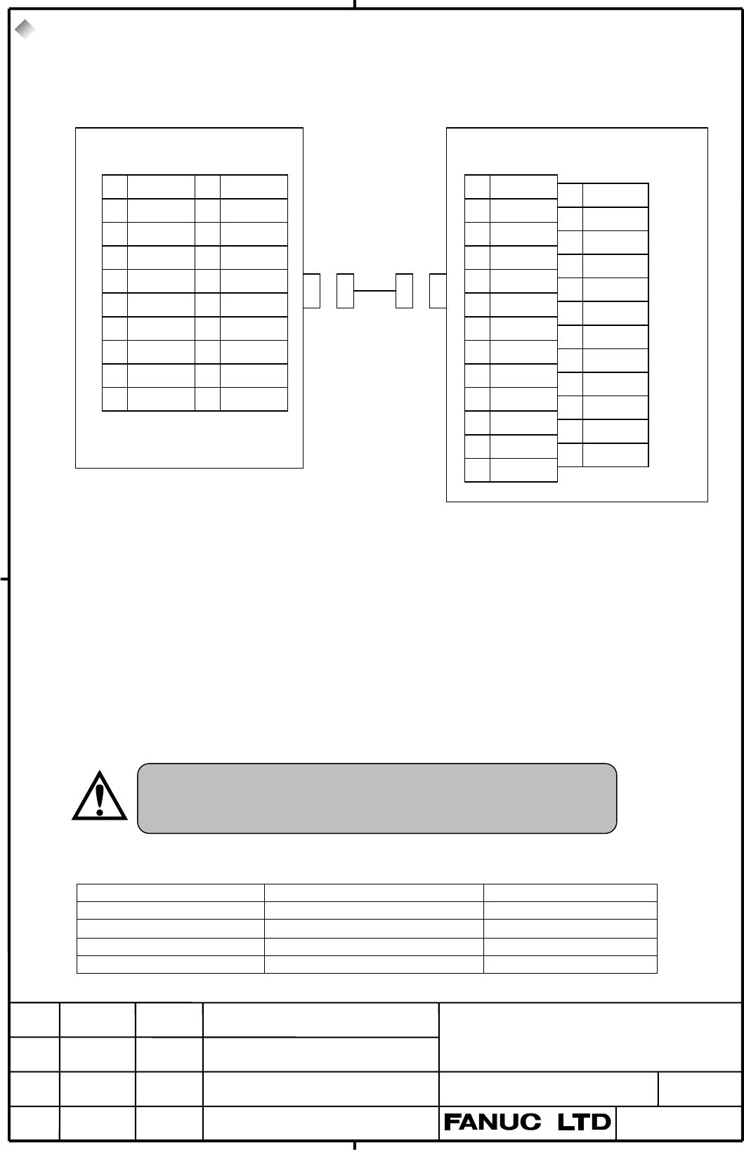
4.3. Serial Port 1
In case of PANEL i with the TOUCH-PANEL, Serial Port 1 is not available. Because the TOUCH-
PANEL CONTROLLER uses the 1st port of RS-232-C.
Note 1) The figure shows a sample host computer interface. Design the cable to suit the interface
of the actual device to be connected.
Note 2) The +24V pins of the interface for PANEL i shown above can be used only with the
FANUC I/O unit. Do not use these pins for other purposes. Also, do not attempt to
simultaneously connect two or more FANUC I/O units to one PANEL i.
1) RECOMMENDED CABLE MATERIAL
A66L-0001-0284#10P・・・0.08mm
2
X 10 pairs
2) RECOMMENDED PUNCH PANEL
A02B-0236-C191 (1m), A02B-0236-C192 (2m), A02B-0236-C193 (5m)
3) RECOMMENDED CONNECTOR FOR CABLE and HOUSING(JD33 side)
CONNECTOR HOUSING MAKER
PCR-E20FA PCR-V20LA/PCS-E20LA (Honda Tsushin Kogyo)
FI30-20S FI-20-CV2/FI-20-CV7 (Hirose Electric)
FCN-247J020-G/E FCN-240C020-Y/S (Fujitsu)
52622-2011 52624-2015 (Molex Japan)
The other punch panel (A02B-0120-C191 – C193) for CNC
cannot be used on PANEL i. If inappropriate punch panel is
used, a system can’t run or serious failure may happen.
1RD 11SD
20V 120V
3DR 13ER
40V 140V
5CS 15RS
6 (Reserve) 16 (Reserve)
7CD 17(Reserve)
8 (Reserve) 18 (Reserve)
9 RI 19 (+24V)
10 (+24V) 20 (Reserve)
( ):Used with FANUC
I/O device.
1FG
2SD
3RD
4RS
5CS
6DR
7SG
8CD
9
10
11
12
13
14
15
16
17
18
19
20 ER
21
22 RI
23
24
25
*(Reserve) pins must not connect.
ex.)Host Computer
PANEL
i
JD33 (PCR-E20MD) (DBM-25S)
04 01.04.01 Sugitani All page changed
Contents Summary of Connecting and Maintenance Manual for Fanuc Panel I Additional Manual
- Page 1TECHNICAL REPORT (MANUAL) NO. TMN 02/034 Date: 22. March 2002 General Manager of Hardware Laboratory Connecting and Maintenance Manual for FANUC PANEL i 1. Communicate this report to: O Your information only O GE Fanuc-N, GE Fanuc-E FANUC Robotics CINCINNATI MILACRON O Machine tool builder Sales age
- Page 2Introduction 5 This manual describes mounting information of the FANUC PANEL i or CNC display unit with Peasonal Computer function (Old name: Intelligent Terminal with PCI Bus) with the following FANUC CNC to the machine tools. In case of using the FANUC PANEL i with FANUC CNC, refer to manuals for
- Page 3ATTENTION - The copyright of Windows R 2000, Windows NT R 4.0, Windows R 95, Windows R 98 and other software provided with the PANEL i is owned by Microsoft Corporation (USA), NeoMagic Inc., Phoenix Technologies Ltd., PFU Co.,Ltd, and FANUC LTD. - No part of the software described above, or its manu
- Page 4Connecting and Maintenance Manual for FANUC PANEL i CONNECTING TITLE Connecting and Maintenance Manual for FANUC PANEL i DRAW. NO. CUST 04 01.04.01 Sugitani All page changed A-81000E SHEET EDIT DATE DESIG. DESCRIPTION 3 / 79�
- Page 5INDEX I. CONNECTING Page 1. Total Connection 5 1.1. Without Soft-Key & Touch-Panel 5 1.2. With Soft-Key, Without Touch-Panel 6 1.3. With Touch-Panel, Without Soft-Key 7 1.4. With Soft-Key and Touch-Panel 9 2. Specifications 11 2.1. Hardware specifications 11 2.2. Environment 13 2.3. Power Specificat
- Page 61. Total Connection 1.1. Without Soft-Key & Touch-Panel : Optical link Module & Cable CNC Control : AMP(Dynamic) : AMP(mini-DIN6pins) POWER SUPPLY : HONDA TSUSHIN(PCR 20pins) HSSB I/F BOARD : HIROSE DENKI(Flat Cable34pins) HSSB(COP7) : HIROSE DENKI(Flat Cable40pins) THE OTHER PCB : AMP(EI Series 4pi
- Page 71.2. With Soft-Key, Without Touch-Panel : Optical link Module & Cable : AMP(Dynamic) CNC Control : AMP(mini-DIN6pins) POWER SUPPLY : HONDA TSUSHIN(PCR 20pins) HSSB I/F BOARD : HIROSE DENKI(Flat Cable34pins) HSSB(COP7) : HIROSE DENKI(Flat Cable40pins) THE OTHER PCB : AMP(EI Series 4pins) In case of 1
- Page 81.3. With Touch-Panel, Without Soft-Key : Optical link Module & Cable CNC Control Unit : AMP(Dynamic) : AMP(mini-DIN6pins) POWER SUPPLY : HONDA TSUSHIN(PCR 20pins) HSSB I/F BOARD HSSB(COP7) : HIROSE DENKI(Flat Cable34pins) THE OTHER PCB : HIROSE DENKI(Flat Cable40pins) In case of 150i (JA2) : AMP(EI
- Page 9For connections other than those illustrated above, refer to the connecting manual for the CNC main unit. 04 01.04.01 Sugitani All page changed TITLE Connecting and Maintenance Manual for FANUC PANEL i DRAW. NO. CUST A-81000E SHEET EDIT DATE DESIG. DESCRIPTION 8 / 79�
- Page 101.4. With Soft-Key and Touch-Panel : Optical link Module & Cable : AMP(Dynamic) CNC Control : AMP(mini-DIN6pins) POWER SUPPLY : HONDA TSUSHIN(PCR 20pins) HSSB I/F BOARD : HIROSE DENKI(Flat Cable34pins) HSSB(COP7) : HIROSE DENKI(Flat Cable40pins) THE OTHER PCB In case of 150i (JA2) : AMP(EI Series 4p
- Page 112. Specifications 2.1. Hardware specifications Item Specification CPU Pentium III 500MHz or Celeron 400MHz or MMX-Pentium 233MHz (Celeron 400MHz is succession of PentiumII 333MHz) Memory 32MB, 64MB or 128MB (32MB can be specified only in case of MMX-Pentium) LCD 10.4” color LCD (640x480dots, 65536 c
- Page 12Item Specification for 10.4” LCD type3.6kg (PANEL i) 3.5kg (FA Full-keyboard with 3.5”HDD unit for vertical) 2.9kg (MDI with 3.5”HDD unit for vertical) 2.7kg (MDI with 3.5”HDD unit for horizontal) Weight for 12.1” LCD type 4.5kg (PANEL i) 3.7kg (FA Full-keyboard with 3.5”HDD unit for vertical) 3.2kg
- Page 132.2. Environment When PANEL i is used, the following environmental conditions (as measured top of the PANEL i inside the cabinet) must be ensured for the PANEL i unit installation. Ambient temperature Operating : +5~ +45°C Non-operating : - 20~ +60°C Change in temperature Up to 20 degrees/hour Ambie
- Page 142.3. Power Specification 1) Power Supply Requirement A) Specification When the PANEL i is used, the following power supply is required. Input Voltage DC +24V ± 10% Current (In case of A08B-0082-B001~4, B011~4, Max. 7A capacity B031~4) (In case of A08B-0082-B021~4, B041~4, Max. 10A B051~4) Note: If H
- Page 152.4. Shutdown operation Be sure to finish the OS and the applications through the proper operation of shutdown before turning the power off. Without the above-mentioned operation, there is no assurance of the following action. At worst, the command of initializing the HDD will not work 04 01.04.01 S
- Page 163. Mounting Space The following three spaces are required around the PANEL i. A: Space for connecting cables. Also, If you wish to exchange a battery or a fuse without removing PANEL i from the machine panel, this space A is required and it is necessary to be able to access to the battery or the fus
- Page 173.2. Basic Unit 12.1” LCD Type 60 In case that PCI Extension Board Fitting Plate is ordered. 20 C C A A 57 B X B Fuse Battery Refer to APPENDIX about outline dimensions of the basic unit. Unit: mm 3.3. Basic Unit 15.0” LCD Type 60 In case that PCI Extension Board Fitting 0 Plate is ordered. C C A A
- Page 183.4. HDD Unit The HDD unit is mounted on the backside of the MDI or the FA Full-Keyboard. FA Full Keyboard FAN HDD Unit or MDI Unit C C 30 20 Refer to APPENDIX about outline dimensions of the FA full keyboard and the position of the HDD unit. Unit: mm Reserve space C in the above figure. And reserve
- Page 194. Connection to Peripheral 4.1. Connector Location PCMCIA Card slot (Display side) View from The back side CNP1 CNP2 JD33 JD46 JD9 CN2B CN2 CD32B CD32A CP5 COP7 CNH3 CD34 CN7 Soft-key (Connect to separate MDI) Connector Connector Name Function Reference Number CP5 +24V INPUT Main Power Input to Sec
- Page 204.2. Main Power Input PANEL i CP5 1 +24V 2 0V DC+24V 3 AMP 2-178288-3 (CASE) 1-175218-5 (CONTACT) 1) Cable Wiring 1 +24 +24 2 0V 0V 2) Recommended Cable Material Use wire of AWG#16 (1.3mm2)or thicker. Note 1) Please wire this cable separately from the other cables connected to PANEL i. TITLE Connect
- Page 214.3. Serial Port 1 In case of PANEL i with the TOUCH-PANEL, Serial Port 1 is not available. Because the TOUCH- PANEL CONTROLLER uses the 1st port of RS-232-C. PANEL i ex.)Host Computer JD33 (PCR-E20MD) (DBM-25S) 1 RD 11 SD 1 FG 14 2 0V 12 0V 2 SD 15 3 DR 13 ER 3 RD 16 4 0V 14 0V 4 RS 17 5 CS 15 RS 5
- Page 224.4. Serial Port 2 +USB PANEL i ex.)Host C JD46 (PCR-E20MD) (Dsub 9 i ) 1 RD 1 SD 1 CD 1 6 DR 2 RD 2 0V 1 USB1_0V 7 RS 3 SD 2 8 CS 4 ER 3 DR 1 ER 9 RI 5 SG 3 4 0V 1 USB2_0V 4 5 CS 1 RS 5 6 USB1+ 1 USB2+ 6 7 CD 1 USB2- Note 1) The figure shows a sample host computer interface and USB. Design the cabl
- Page 231) RECOMMENDED CABLE MATERIAL SPEC. For RS232-C : A66L-0001-0284#10P・・・0.08mm2 10 pairs For USB : Please use special wire for USB 2) RECOMMENDED PUNCH PANEL A02B-0236-C191 (1m), A02B-0236-C192 (2m), A02B-0236-C193 (5m) The other punch panel (A02B-0120-C191 – C193) for CNC cannot be used on PANEL i.
- Page 244.5. Parallel Port PANEL i ex.)PRINTER JD9 (PCR-E20MD) 1 STD0 11 *STB 1 *STB 19 0V 2 STD1 12 0V 2 STD0 20 0V 3 STD2 13 *AFD 3 STD1 21 0V 4 STD3 14 0V 4 STD2 22 0V 5 STD4 15 *INIT 5 STD3 23 0V 6 STD5 16 0V 6 STD4 24 0V 7 STD6 17 *SLIN 7 STD5 25 0V 8 STD7 18 *ACK 8 STD6 26 0V 9 PE 19 *ERROR 9 STD7 27
- Page 254.6. High Speed Serial Bus (HSSB) HSSB Interface Board (CNC side) PANEL i Optical Fiber Cable COP7 COP7 1) RECOMMENDED CABLE(Optical Fiber Cable) A66L-6001-0026#L1R003・・・Cable Length = 1 m A66L-6001-0026#L3R003・・・Cable Length = 3 m A66L-6001-0026#L5R003・・・Cable Length = 5 m A66L-6001-0026#L7R003・・・C
- Page 264.7. Mouse PANEL i Mouse (in the market) CD32B (mini-DIN6) 6 5 MSCLK 4 +5V 3 0V MS 2 1 MSDATA or FA Full Keyboard Mouse (in the market) Note 1) Some kinds of Mouse may not work properly with PANEL i, so careful checking by the customer will be required. And please be aware that Mouse in the market i
- Page 274.8. Full Keyboard PANEL i Full Keyboard (in the market) CD32A (mini-DIN6) 6 5 KEYCLK 4 +5V 3 0V KB 2 1 KEYDATA or FA Full Keyboard Note 1) Some kinds of Full Keyboard may not work properly with PANEL i, so careful checking by the customer will be required. And please be aware that Full Keyboard in
- Page 284.9. Hard Disk Drive 1) Cable Connection Connect HDD Signal cable to CNH3. Connect HDD Power cable to CN2B. Connect FAN cable to CN7. Each cables are connected to HDD unit at exfactory. 2) Cable Length HDD Power Cable: 50cm HDD Signal Cable: 40cm HDD FAN Cable: 65cm PANEL i CNH3 CN2B CN7 HDD Signal
- Page 294.10. Floppy Disk Drive (Signal & Power) PANEL i 3.5” F loppy Disk Dr ive A CD34 1 0V 2 DE NSEL 1 0V 2 DE NSEL 3 0V 4 3 0V 4 5 0V 6 5 0V 6 7 0V 8 *INDE X 7 0V 8 *INDE X 9 0V 10 *MT0 9 0V 10 *DS0 11 0V 12 *DS1 11 0V 12 *DS1 3.5”F loppy Disk 13 0V 14 *DS0 Dr ive B 13 0V 14 (Reser ve) 15 0V 16 *MT1 15
- Page 301) Cable Wiring CD34 J1 1 1 1 0V 0V 2 2 2 DE NSE L DE NSE L 3 3 3 0V 0V 4 4 4 (NC) (NC) 5 5 5 0V 0V 6 6 6 (NC) (NC) 7 7 7 0V 0V 8 8 8 *INDE X *INDE X 9 9 9 0V 0V 10 10 16 *MT0 *DS0 11 11 15 0V 0V 12 12 14 *DS1 *DS1 13 13 13 0V 0V 14 14 12 *DS0 (Reser ve) 15 15 11 0V 0V 16 *MTRON P a n n el Mou n t T
- Page 314.11. Soft-Key Separate MDI PANEL i CNK2 1) Cable Length: 50 cm 4.12. PCMCIA Card PANEL i Door PCMCIA Card slot Back side PCMCIA card (Type I, Type II) Note 1) Only Type I or Type II PCMCIA card is usable. The following card cannot be used. - Card-bus card - Dual mode card (Card-bus mode/ 16bit PC C
- Page 325. Method of Mounting PCI Extension Board 5.1 Usable Board The size of usable board on the PANEL i is defined as below figure, and one or two boards can be mounting on the PANEL i. P a r t s h eigh t of ba ck side : u p t o 3m m P a r t s h eigh t of fr on t side : u p t o 13m m Fix by screw Up t o
- Page 335.2 Method of mounting PCI extension board ○1 Release vibration-proof fittings by loosening the screw at point (B). ○2 Push the board fully into the PCI connector. ○3 Tighten the screw at point (A). ○4 Press down vibration-proof fittings to the PCI extension board and tighten the screw at point (B).
- Page 34MANTENANCE If an operation error or mishap occurs, the data on the hard disk may be lost, even if all the installation conditions are satisfied. Therefore, always maintain a backup copy of the data on the hard disk in case the stored data is lost or damaged. Especially, the power-off on accessing th
- Page 35INDEX II. MAINTENANCE page 1. System Block Diagram 33 2. List of the PCBs, Units, Maintenance Supplies and 35 Tools 2.1. List of PCBs 35 2.2. List of Units 36 2.3. List of CardPC and Memory 38 2.4. List of Maintenance Supplies 38 2.5. List of Maintenance Tools 39 3. Configuration of the PCB 40 3.1.
- Page 361. System Block Diagram In case that Touch Panel is mounted. CP1 CD37 Touch Panel Control PCB Main PCB FDD SIGNAL CD34 FDD POWER CN4 CN2 LCD CENTRO Signal CN1 PC JD9 CN1B Card DV/RV RS232-2/USB JD46 15.0”LCD only RS232-1 DV/RV JD33 KEYBOARD BAT1 CD32A MOUSE CD32B 10.4” LCD, 12.1” LCD, or 15.0”LCD Ba
- Page 37*1 : Detail of Inverter section In case of A08B-0082-B001~4, B011~4 or B021~4 Main PCB of In case of 10.4”LCD PANEL i 10.4”LCD Inverter (A20B-2100- Unit CN2 CN1 0690~3) CN3 In case of 12.1”LCD 12.1”LCD Inverter Unit CP1 CP2 CP31 In case of 15.0”LCD 15.0”LCD Inverter Unit CN02 CN01 CN03 CN04 CN05 In
- Page 382. List of the PCBs, Units, Maintenance Supplies and Tools 2.1. List of PCBs Name Spec. Main PCB For Windows For 10.4”/12.1 LCD A20B-2100-0690 (for basic unit A08B- 95 type 0082-B001~4, B011~4 For 15.0” LCD type A20B-2100-0691 or B021~4) For not For 10.4”/12.1 LCD A20B-2100-0692 Windows 95 type For
- Page 392.2. List of Units Name Specification of Specification of Base Unit Touch Master Unit LCD Type SoftKey Maintenance Unit (Not Panel (Basic Unit) including 10.4” LCD A08B-0082-D001 A08B-0082-B001, X X Main PCB) A13B-0193-B001 A08B-0082-D002 A08B-0082-B002, O X A13B-0193-B002 A08B-0082-D003 A08B-0082-B
- Page 40Name Specification of Specification of Base Unit LCD Touch Master Unit O/S SoftKey Maintenance Unit (Not Type Panel (Basic Unit) including 10.4 not X X A08B-0082-D031 A08B-0082-B031 Main PCB) ” Windows O X A08B-0082-D032 A08B-0082-B032 LCD 95 X O A08B-0082-D033 A08B-0082-B033 O O A08B-0082-D034 A08B
- Page 412.3. List of Card PC & Memory Name Specification of Specification of Maintenance Unit Master Unit PC MMX-Pentium 10.4” LCD A08B-0082-H500#6132 A08B-0082-H010, Card 233MHz Type A08B-0082-H500#6141 A13B-0193-H010 12.1” LCD A08B-0082-H500#6133 A08B-0082-H011, Type A08B-0082-H500#6142 A13B-0193-H011 15.
- Page 422.4. List of Maintenance Supplies Name Spec. Fuse (for basic unit A08B-0082-B001~4, B011~4 or A02B-0236-K101 B031~4) Fuse A08B-0082-K001 (for basic unit A08B-0082-B021~4, B041~4 or B051~4) Battery A02B-0200-K102 Fan for Basic Unit A08B-0082-K010 Fan for HDD A13B-0178-K001 LCD Backlight for 10.4” LCD
- Page 433. Configuration of the PCB 3.1. Parts Layout *4 CN1B (LCD) (Unit Fan CN6 Power) CN1 (LCD) Power Controller PCMCIA Controlle r Peripheral Controller TM10 CN5 (PCMCIA) CNP1 ( PCI ) CNP2 ( PCI ) CN4 *4 (Inverter) (Card PC) CN3 HSSB (7.5A) Controller *4 (FDD (10A) CN2B CN2 FUSE-1 CD32B CD32A Power) (HD
- Page 44*5 CN1B (LCD) (Unit Fan CN6 Power) CN1 (LCD) Power Controller PCMCIA Controlle r Peripheral Controller TM10 CN5 (PCMCIA) CNP1 ( PCI ) CNP2 ( PCI ) *5 CN4 *5 (Inverter) (Card PC) CN3 CN3B HSSB (7.5A) Controller *5 (FDD (10A) CN2B CN2 FUSE-1 CD32B CD32A Power) CN7 (HDD Fan MOUSE Keyboar d JD46 BAT1 (H
- Page 453.2. Adjustment (1) Settings of Short Plugs Name Meaning Settings SW5 Reserved Default on SW5 : Open SW7 manufacture. (A20B- : Short 2100-069*) Never change. : If Option for Non- SW7 Connecting with CNC is ordered, SW5 is SW5 Reserved Default on SW5 short. But it is not TM7 manufacture. (A20B- order
- Page 464. BIOS SET-UP 4.1. What is “BIOS SET-UP” “BIOS Set-up” is a program to set up BIOS settings, and operating environment for the PANEL i is defined by these BIOS settings. It is unnecessary to run the set-up program normally because default BIOS settings are set at shipping. And use PANEL i with this
- Page 474.3. How to Begin the “BIOS SET-UP” 1. Finish to work and store the data. 2. Turn off the power, and connect a full-keyboard, and turn on the power again. 3. BIOS set-up will run with pressi ng “F2” key from completing memory check till loading OS as of 22.Aug.2000. If battery is not supplied in suc
- Page 484.5. BIOS Diagnostic Message After turn on the system, POST (Power On Self Test) is executed. Diagnosis messages as the following table may be displayed. Marks in item “To be solved” represent as bellow. O: Something of hardware is failure. Exchanging PC card or etc. is required. 1 : When battery su
- Page 495. Maintenance Supplies 5.1. Method of Exchanging Battery The time from disconnecting the cable of old battery to connecting the cable of new battery should be shorter than 5 minutes. BIOS settings are not erased when bellow procedures are done correctly. But if BIOS settings are erased, following m
- Page 505.2. Method of Exchanging Fuse Investigate the cause that fuse is blown out at first, then remove it. Fuse is blown out when power lines are shorted in PANEL i. If the fuse is blown out, check bellow points. - Any conductor is shorted to the main board. - Failure of PCI extended card or error at ins
- Page 515.3. Method of Exchanging FAN 5.3.1. Method of Exchange FAN of the Basic Unit (1) Make sure that PANEL i is turned off the power. (2) Prepare a new Fan (A08B-0082-K010). (3) Screw off at 2 points (A) then remove holding plate of the FAN. (4) Pull out the connector of fan power. This connector has a
- Page 52Holding plate of the fan Wire cable as below figure. fan A08B-0082-K010 confirm the direction Pay attention to the direction of Air Flow this cable 2 points of screw (B) In case of A08B-0082-B031~4, B041~4 or B051~4 TITLE Connecting and Maintenance Manual for FANUC Intelligent Terminal DRAW. NO. CUS
- Page 535.3.2. Method of Exchanging FAN for the HDD unit (1) Make sure that PANEL i is turned off the power. (2) Prepare a new Fan (A13B-0178-K001). The connector is latched, and disconnect with raising upward the connector a little. (3) Disconnect the Fan connector from CN7 (4) Screw off at 2 points fixing
- Page 545.4. Method of Exchanging LCD Backlight Note) It is not possible to exchange only backlight of 15.0”LCD. Exchanging of LCD panel is available in case of 15.0”LCD. Please exchange the backlight after taking off the basic unit from the cabinet or operation panel for prevention of dropping LCD unit or
- Page 55(3) Screw off at 4 points and take off the plastic panel. Plastic Panel Plastic Panel In case of 12.1” LCD In case of 10.4”LCD (4) Pull out cable(s) of the LCD backlight and LCD signal connecotr CN1. CN1 LCD In case of 12.1” LCD In case of 10.4”LCD TITLE Connecting and Maintenance Manual for FANUC I
- Page 56(5) Screwed off at 4 points and remove LCD. LCD LCD In case of 12.1”LCD In case of 10.4”LCD TITLE Connecting and Maintenance Manual for FANUC Intelligent Terminal DRAW. NO. CUST A-81000E 04 01.04.01 Sugitani All pages changed. SHEET EDIT DATE DESIG. DESCRIPTION 53 /
- Page 57(5a) In case of 10.4”LCD type , Unlock like the below figure, pull out the case with the backlight, and exchange. Locked here CP1 Pull up her softly and pull out the backlight (detail is below figure) Rear of LCD Lock Pull up here Do not pull the cable when pull out the backlight. TITLE Connecting a
- Page 58(5b) In case of 12.1”LCD type , screw off at 2 points. And slide and pull out the LCD Backlights as below figure, and exchange them. Connector 2. Pull out 1. Slide CP31 EJECT CN1 The backside of LCD Panel Connector CP1 EJECT Back light (upper) Back light (lowwer) Do not pull the cable when pull out
- Page 595.5. Method of Exchanging Touch Panel Protection Sheet PANEL i has a T ouch Panel Protection Sheet on the face of Touch Panel to protect the Touch Panel. When the screen cannot be watched clearly because of some damages or stains, exchange the Touch Panel Protection Sheet. Please prepare the followi
- Page 606. Trouble Shooting Trouble Measure 1 Power supply is good, - Are LED all off? Yes Go to 11 but nothing displayed. No - Is Option for Independently Use ordered? No Yes - Is RE1 (Red, Refer to Maintenance 3.3) on? Go to 2. Yes No - Is RE2 on? It is not in proper temperature. Are LED displaying Yes (R
- Page 61No Cause Measure 5 Boot up from CD-ROM. When CD-ROM drive is connected to PANEL i and bootable CD- ROM is inserted to the drive, PANEL i starts up from CD-ROM. Please remove CD-ROM at starting up. (There is no item about boot device in BIOS settings). 11 Power is not good. - Is the fuse blown out? E
- Page 62APPENDIX Index III APPENDIX Page 1. Outline Table 60 1.1 Outline Table Basic Unit 60 1.2 Outline Table FA full keyboard/MDI unit 61 2. Basic Unit 63 2.1 Basic Unit 10.4” LCD 63 2.2 Basic Unit 12.1” LCD 64 2.3 Basic Unit 15.0” LCD 65 3. FA Full Keyboard 66 3.1 FA Full Keyboard 10.4” LCD 66 3.2 FA Ful
- Page 636. Keyboard / Mouse 76 6.1 Full Keyboard 101/106 key 76 6. Keyboard / Mouse 76 6.1 Full Keyboard 101/106 key 76 6.2 Mouse 77 7. Hard disk drive unit 77 7.1 Hard disk drive unit 77 8. Panel Cutting 79 APPENDIX II 5 Method of exchanging Touch Panel Protection Sheet 79 (A02B-0236-K130) TITLE Connecting
- Page 641. Outline Table 1.1 Outline Table Basic Unit Name Specification Remark Outline A08B-0082-B001, 10.4” color LCD, without Touch Panel, without Softkey A13B-0193-B001 A08B-0082-B002, 10.4” color LCD, without Touch Panel, with Softkey A13B-0193-B002 2.1 A08B-0082-B003, 10.4” color LCD, with Touch Panel
- Page 651.2 Outline Table FA Full Keyboard/ MDI Unit Name Specification Remark Outlin e FA Full Keyboard #EC English, 220x290 1 A02B-0236-C131 3.1 FA Full Keyboard #JC Japanese,220x290 2 FA Full Keyboard #EC English, 220x340 3 A02B-0236-C132 3.2 FA Full Keyboard #JC Japanese,220x340 4 FA Full Keyboard #EC E
- Page 66Separate type MDI 32 #MCS For 150i, 61key, Symbol, Horizon, 280x230 For 160i/180i/210i-B Standard key, English, Separate type MDI 33 #TBR Horizon,220x230,T Separate type MDI 34 #MBR For 160i/180i/210i-B Standard key, English, Horizon,220x230,M A02B-0281-C320 4.5 For 160i/180i/210i-B Standard key, Sy
- Page 672. Basic Unit 2.1 Basic Unit 10.4” LCD Type 125 (With PCI Extension Board Fitting Plate) 60 (Without PCI Extension Board Fitting Plate) 25 2 20 Upper Paint Masking View (Mounting side of this plate is unpainted in 4-Ø4 8mm width from the edge 290 5 ) Maximum PCI card defined at Connecting 5. 220 210
- Page 682.2 Basic Unit 12.1” LCD Type 125 (With PCI Extension Board Fitting Plate ) 60 (Without PCI Extension Board Fitting Plate ) 30 2 25 Upper Paint Masking View (Mounting side of this 340 plate is unpainted in 5 8mm width from the edge.) 270 280 (From the outside of the plate) 6-Ø4 57 5 5 165 165 5 Side
- Page 692.3 Basic Unit 15.0” LCD Type 125 (With PCI Extension Board Fitting Plate ) 60 (Without PCI Extension Board Fitting Plate ) 35 2 30 Paint Masking Upper (Mounting side of this View plate is unpainted in 400 8mm width from the 5 edge ) 155 (From the outside of the plate) 320 155 77 8-Ø4 5 5 195 195 5
- Page 703. FA Full Keyboard 3.1 FA Full Keyboard 10.4” LCD Type Specification: A02B-0236-C131#JC,A02B-0236-C131#EC 1550±40 250±40 2 60.6 29 2 0 0 22 0 1 6 5 0 4-Ø4 32 a 5 a Refer to section 8 about panel cutting. 60 56 a: M5 M4 x 10mm b: M5 M4 x 10mm(Frame GND) 5 a 30 b Weight : 3.5 kg 40 a (Unit :mm) 20 TI
- Page 713.2 FA Full Keyboard 12.1” LCD Type Specification: A02B-0236-C132#JC,A02B-0236-C132#EC 1550±40 250±40 2 34 20 60.6 0 220 10 6 5 6-Ø4 32 a 5 a Refer to section 8 about panel cutting. 110 a: M5 M4 x 10mm 54 b: M5 M4 x 10mm a 5(Frame GND) 30 b a 40 Weight : 3.7 kg (Unit : mm) 20 TITLE Connecting and Ma
- Page 723.3 FA Full Keyboard 15.0” LCD Type Specification: A08B-0082-C150#JC, A08B-0082-C150#EC 1550±40 250±40 2 40 60.6 0 20 220 6-Ø4 26 34 5 35 5.5 13 5 4-R5 Blank Panel 140 155 86 Hole of Connector 168 179 27 Panel 59 b 20 80 Refer to section 8 about 5.5 panel cutting. 2-ø5 Weight :3.9 kg Unpaint rear b:
- Page 734. MDI Unit 4.1 MDI Unit 10.4”LCD Type Vertical 2 10 29 20 0 44.6 22 0 36.1 40 4 0 2 4-Ø4 9 70 0max 11 5 5 a a 10 Refer to section 8 about 107 panel cutting. a: M5 M4 x 10mm b: M5 M4 x 10mm a (Frame GND) 5 83 b 30 Weight :2.9 kg 87 (Unit :mm) 60 a 68. 79. 20 7 0 Note: Arrangement of key top is case
- Page 74Refer to section 8 about panel cutting. 4.2 MDI Unit 12.1”LCD Type Vertical a: M5 M4 x 10mm b: M5 M4 x 10mm Blank Panel (Frame GND) 7 5 Weight : 3.2 kg (Unit :mm) 2 Connector Panel 340 10 20 44.6 220 36. 1 40 4 20 0 5 70 6-Ø4 11 4 9 26 7 35 5.5 5 a a Blank 4-R5 101 Panel 66 Hole of 155 Connector 168
- Page 754.3 MDI Unit 10.4” LCD Type Horizon 2 10 20 230 44.6 220 36.1 40 40 20 11 5 70 max 4-Ø4 9 5 a a 11 Refer to section 8 about panel cutting. 10 a: M5 M4 x 10mm 46 b: M5 M4 x 10mm a (Frame GND) 5 a Weight : 2.7 kg 53 (Unit : mm) 20 57 60 a b 39 79.0 28 Note: Arrangement of key top is case of standard k
- Page 76Refer to section 8 about 4.4 MDI Unit 12.1” LCD Type Horizon panel cutting. a: M5 M4 x 10mm 7 5 b: M5 M4 x 10mm (Frame GND) 2 10 230 20 Weight : 3.1 44. kg 6 (Unit : mm) 280 36. 1 Connector Panel 40 100 79 69 70 11 5 4-Ø4 a 5 35 a 1 Blank Panel 0 101 a Hole of Connector Panel 53 179 14 a b 57 100 79
- Page 774.5 MDI Unit 10.4” LCD Type Horizon for i series model B Refer to section 8 about panel cutting. b: M5 M4 x 10mm 5 (Frame GND) 2 10.7 50.5 230 43.5 220 40 24.5 45.5 14.5 4-F 4 9 42. 4 5 9 70max. 5 35 21.8 57.6 53.1 63 b 16 24 177 18 39 79 TITLE Connecting and Maintenance Manual for FANUC PANEL i 05
- Page 784.6 MDI Unit 10.4” LCD Type Vertical for i series model B Refer to section 8 about panel cutting. b: M5 M4 x 10mm (Frame GND) 5 2 10.7 50.5 290 43.5 220 40 24.5 45.5 14.5 9 42. 4 70max. 5 9 5 65 51.8 87.6 83.1 63 b 34 54 177 35 69 79 TITLE Connecting and Maintenance Manual 05 02.03.07 Sugitani Marke
- Page 795. Floppy Diskette Drive 5.1 Floppy Diskette Drive Specification: A02B-0207-C008 5 4-ø3.6 FDD J2 150 140 ACRYLIC WINDOW 104 J1 5 5 70 5 145 80 (Unit : mm) Front Side View View 4-M3 134 5 140 64 Weight : 0.8kg (HOLE) 70 Panel Cutting TITLE Connecting and Maintenance Manual 05 02.03.07 Sugitani Marked
- Page 806. Keyboard / Mouse 6.1 Full Keyboard 101/106 key 205 (Unit : mm) Full Keyboard 101key( A86L-0001-0210) 200 (Unit : mm) Full Keyboard 106key( A86L-0001-0211) Note: This unit can be used only during application development and maintenance ,and this is not dust proof. Ambient temperature during operat
- Page 816.2 Mouse Specification: A86L-0001-0212 Cap Ball 1800±190 Name Plate of Unit (Unit : mm) Note: This unit can be used only during application development and maintenance ,and this is not dust proof. .Ambient temperature during operation is 0°C-40°C. TITLE Connecting and Maintenance Manual for FANUC P
- Page 827. Hard disk drive unit 7.1 Hard disk drive unit Specification: A08B-0082-C100 44.6 37.6 6 66 136 42 40 3 6 28 25 83 9 TITLE Connecting and Maintenance Manual for FANUC PANEL i DRAW. NO. CUST 04 01.04.01 Sugitani All pages changed. A-81000E SHEET EDIT DATE DESIG. DESCRIPTION 78 / 79�
- Page 83Method of exchanging Touch Panel Protection Sheet (A02B-0236-K130) 1. At first, strip the old Touch Panel Protection Sheet off. Tab for exchange 2. Clean the face of the LCD well. 3. Strip the film on the back of the new Touch Panel Protection Sheet (this side is to stick on the LCD face.) off. 4. P