Order Specification for Servo HRV3 Function Additional Manual Page 8
Additional Manual
Edit. DATE Design
Description
DRAW. NO.
A-65428E
CUST.
01 00/08/22
New issue
SATOU
FANUC Series 15i
Order specification for Servo
HRV3
SHEET
7 /
17
TITLE
CNC Main CPU
or Additional axes board
Servo control card
COP10A-2
COP10A-1
COP10B (1)
COP10A
COP10B (2)
COP10A
COP10B (3)
COP10A
COP10B
COP10A
CP11A
CNF1
COP10B (4)
COP10A
DC24V
COP10B (5)
COP10A
COP10B (6)
COP10A
COP10B (7)
COP10A
COP10B
COP10A
CP11A
CNF1
COP10B (8)
COP10A
DC24V
•
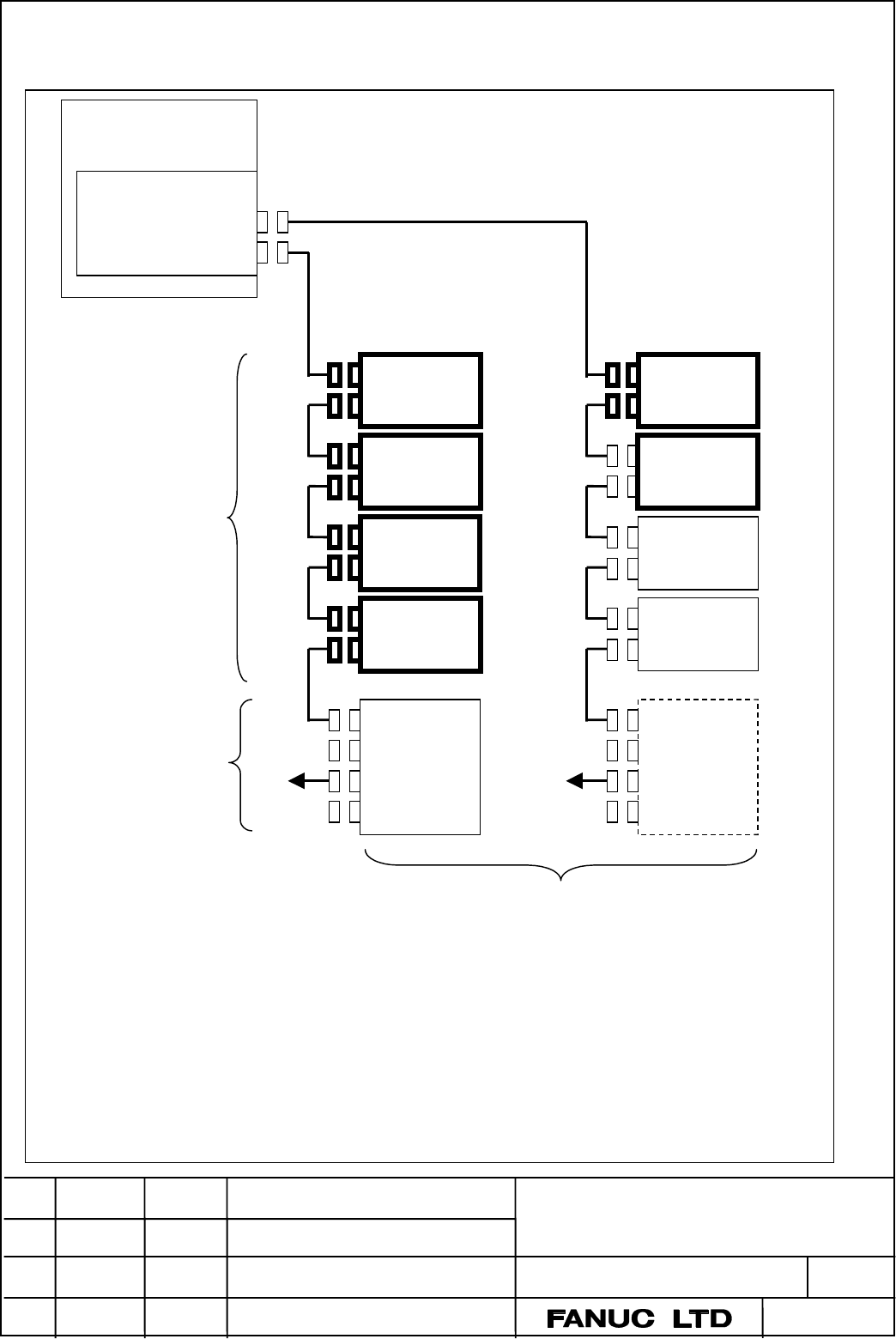
The maximum total number of axis in High speed HRV current control line is 4.
•
The maximum total number of axis and Separate Detector I/F unit in High speed HRV current control line is 5.
•
When the total number of axis and Separate Detector I/F unit in high speed HRV current control line is 5. The Separate
Detector I/F unit should be terminal unit.
•
The maximum total number of axis, which is controlled by one servo card, is 8.
•
The maximum total number of axis and Separate Detector I/F unit, which are controlled by one servo control card, is 10.
•
The servo amplifier from (1) to (2) can be connected to the axis control card for two axes.
•
The servo amplifier from (1) to (4) can be connected to the axis control card for four axes.
•
The servo amplifier from (1) to (6) can be connected to the axis control card for six axes.
•
The servo control card for two and four axes is type A, and the servo control card for six and eight axes are type B.
Servo amplifier:
In this case, all axes are
controlled by the single
axis amplifiers for servo
HRV3
or for high speed HRV
current control.
The total axis number is 8.
The High speed HRV
current control is set the
axes with bold frame.
The amplifier of these axes
should be the one for High
speed HRV current control.
The figures with () are axis
number.
Separate detector I/F
unit
•
This unit should be the
one for Servo HRV3.
It is possible that this
unit is connected to 1st
line or 2nd
line.
4-1 Example. In case of using High-speed HRV current control, the all units in FSSB line are
the available for HRV3
High speed
HRV current
control
Contents Summary of Order Specification for Servo HRV3 Function Additional Manual
- Page 1TECHNICAL REPORT (MANUAL) NO.TMN 00/127E N o. HLB2-00/8153 Date 22.Aug.2000 General Manager of Hardware Laboratory FANUC Series 15i-MA Order specification for Servo HRV3 function 1. Communicate this report to : Your information ! GE Fanuc-N, GE Fanuc-E FANUC Robotics CINCINNATI MILACRON ! Machine to
- Page 2FANUC Series 15i-MODEL Order specification for Servo HRV3 function 1.Outline This document is described the order specification for Servo HRV3 function and the conditions to specify. Generally in case the Servo HRV3 function is used, only Servo amplifier for Servo HRV3 is used. The document is expla
- Page 3Separate Detector I/F unit (Basic 4 axes) (1) For Servo HRV3: All functions of Servo HRV3 can be used. (2) The present unit: This unit cannot be used for Servo HRV3. This unit cannot be used with the servo control card for Servo HRV3. Note) The unit for additional 4 axes can be connected to both the
- Page 43. Condition of FSSB line in case of using high speed HRV current control 3-1.The amplifier for high speed HRV current control is necessary in case of using high speed HRV current control. And it is necessary that the all amplifiers and the Separate Detector I/F units which, are connected in a FSSB
- Page 53-3.It is necessary to connect Separate Detector I/F unit with the end of the FSSB line when the controlled axes on one FSSB lines is four. However, connected position of Separate Detector I/F unit is not limited if the control axis is below three axes. Separate Detector Separate Detector Servo cont
- Page 63-5-1. For example, in case three amplifiers which are set the high speed HRV current control and one present one is used, the pair axis (3rd axis and 4th axis) must be connected to the same FSSB line. Therefor this present amplifier must be set 5th axis and type B servo control card for six axes is
- Page 74. Connection Two optical connectors for FSSB line is mounted on the type B servo control card. The connector of 1st FSSB line is COP10A-1 The connector of 2nd FSSB line is COP10A-2 One optical connector for one FSSB line is mounted on the type A servo control card. The connector of 1st FSSB line is
- Page 84-1 Example. In case of using High-speed HRV current control, the all units in FSSB line are the available for HRV3 CNC Main CPU or Additional axes board Servo control card COP10A-2 COP10A-1 Servo amplifier: In this case, all axes are controlled by the single axis amplifiers for servo HRV3 COP10B (1
- Page 94-2. Example. In case of using high speed HRV present control with the present unit CNC Main CPU or Additional axis board This line include current unit . Therefore, the axis 2nd, 4th, 6th FSSB line optical fiber in this line can not be Type B Servo control card cable adopted to High speed COP10A2 H
- Page 104-3. Example. In case of high speed HRV current control is not used CNC Main CPU Servo control or Additional axis card board COP10A2 COP10A1 COP10B (1) Servo amplifier• COP10A In this case, all axes are controlled by the one axis amplifiers. The total axis number COP10B (2) is 8. The figures with ()
- Page 115.Specification 5-1 Axis control card for Servo HRV3 5-1-1 Axis control card for the Main CPU board (for 3 – 8 axes) Name Specification High speed Type Remark HRV current control Servo control card for B4 A02B-0261-H072 Max. •axes TYPE A ( 1 FSSB note • servo HRV3 for 3 or 4axes line) C4 A02B-0261-H
- Page 12Note 1. Please specify the axis control card for 8 axis for the Main CPU board. In case of high speed HRV current control is used. Please specify the type B axis control card for the Main CPU, and the type A or B card for Additional axis board according to the necessity. In case of high speed HRV cu
- Page 135-1-3 Combination of the axis control card on the Main CPU board and the Additional axis board ( 9-16 axes) •CASE1 In case of High speed HRV current control adapted to more than 13 axes .• Main CPU Type B Axis control High speed HRV current control can be used in four FSSB lines. (Total 16 axes) car
- Page 145-1-4 Axis control card for Additional axis board (for 17-24 axis• Note 1 Specification High speed Type Refer to HRV current 4-1-5 control Additional axis board B10 A02B-0261-J315 Not available Type A+A (2 FSSB CASE 3,4 servo control card for lines) servo HRV3 for 9 or 10 C10 A02B-0261-J325 Max 10ax
- Page 15•CASE2 (In case of High speed HRV current control adapted to 9-20 axes) Main CPU Type B servo control High speed HRV current control can be used in five card 4 axes FSSB lines. (Total 20 axes) COP10A-2 2nd FSSB line If more than five axes are connected to 5th FSSB line, COP10A-1 high speed HRV curre
- Page 16• CASE 4 (In case of High speed HRV current control is not used.) Main CPU Type A servo control card High speed HRV current control cannot be used in COP10A-2 all of FSSB line. COP10A-1 1st FSSB line 8 axes Pleases refer to item 4. Type A servo control card COP10A-2 COP10A-1 5th FSSB line 1-8axes Ty
- Page 175-4. Servo amplifier for Servo HRV3 Name Specification for high Speed for Servo HRV3 HRV current control Alpha servo SVM1-12 A06B-6096-H101#H NG OK Single axis Under 20Ap SVM1-20 A06B-6096-H102#H NG OK SVM1-40S A06B-6096-H103#H OK OK Alpha servo SVM1-40L A06B-6096-H104#H OK OK Single axis SVM1-80 A0
- Page 186.Maintenance 6-1. Axis control P.C.B for Servo HRV3 Name Specification Remark Axis control card A20B-3300-0243 A02B-0261-J311, J315, J325 type A for 2 axes Axis control card A20B-3300-0242 A02B-0261-H072, J312, J316, J336 Type A for 4 axes A20B-3300-0248 A02B-0261-H076, J322, J326 Type B Axis contr