ALPHA Series Servo Amplifier Module (SVM) With FSSB Startup Guide Page 47
Startup Guide
4 - 6 Alpha Series servo Amplifier Module (SVM) with FSSB - April 1998 GFK-1546
4
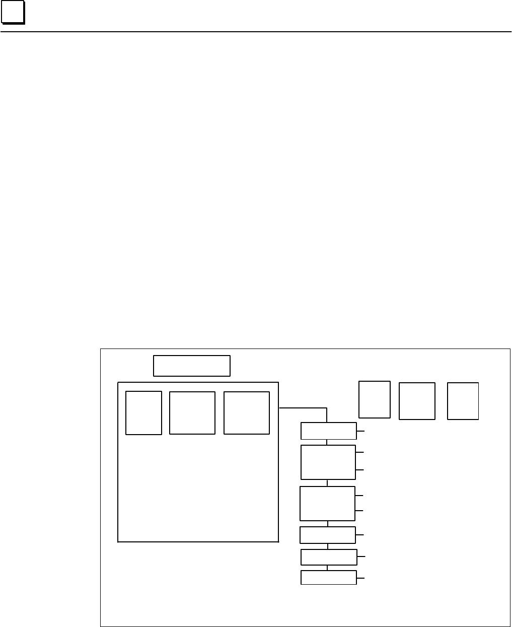
The ATR for each slave must be set. A slave consists of a servo amplifier and pulse module
connected to the CNC by an optical cable. A 2-axis amplifier has two slaves, and a 3-axis
amplifier has three slaves. Each slave is assigned a number, from 1 to 10, according to its
distance from the CNC.
• For an amplifier, set the value which is one less than the value of parameter No. 1023.
• For a pulse module, set 16 for the first pulse module (closest to the CNC) and 48 for the
second pulse module (farthest from the CNC).
• If there is no slave, set 40.
• For the Electric Gear Box function, the EGB dummy axis, designated in parameter No. 7771,
does not require an amplifier. However, do not set 40. Instead, set the values which is one
smaller than the value of parameter No. 1023 for the EGB axis.
Note
When parameter No. 1902#0=0, these bits are set automatically. When
parameter No. 1902#0=1, these bits must be set manually.
Examples of Axis Configuration and Parameter Settings
CNC
L
2-Axis AMP
M
M1
L
2-Axis AMP
M
1-Axis AMP
Axis No.
Servo Axis
No. 1023
Axis Name
No. 1020
X
Y
Z
A
B
C
1
2
3
4
5
6
1
3
4
2
5
6
1 Axis AMP
M2
Slave
No.
Axis
ATR No.
1910-
1919
1
2
3
4
5
6
7
8
9
10
0
1
2
3
4
16
5
48
40
40
X
A
Y
Z
B
M1
C
M2
no slave
no slave
M1/M2 = 1st/2nd pulse module
Contents Summary of ALPHA Series Servo Amplifier Module (SVM) With FSSB Startup Guide
- Page 1GE Fanuc Automation Computer Numerical Control Products α Series Servo Amplifier Module (SVM) With FSSB Servo Setup Manual GFK-1546 April 1998
- Page 2GFL-001 Warnings, Cautions, and Notes as Used in this Publication Warning Warning notices are used in this publication to emphasize that hazardous voltages, currents, temperatures, or other conditions that could cause personal injury exist in this equipment or may be associated with its use. In situ
- Page 3Contents Chapter 1 Descriptions........................................................................................................... 1-1 Chapter 2 FSSB Setting Screens............................................................................................ 2-1 Displaying the FSSB Setting Sc
- Page 4Chapter Descriptions 1 Chapter 1 contains B-65162E/02-25, Alpha Series Servo Amplifier Module (SVM) with FSSB Supplemental Descriptions Manual. GFK-1546 1-1�
- Page 51 This page intentionally left blank. 1-2 Alpha Series Servo Amplifier Module (SVM) with FSSB - April 1998 GFK-1546�
- Page 6I I I I I SERVO AMPLIFIER MODULE WITH _ TITLE FSSB DESCRIPTIONS 01 97.07.11 g@ FIRST EDITION s &;,:’ B-65162E/O2-25 :DIT. D.4TE DESIG. DESCRIPTION FANUC LTD SHEET 001 110 I
- Page 7Table of contents 1. GENERAL . . . 003 2. SPECIFICATIONS . . . 003 2. 1 DES I GNAT IONS . . m003 2.2 SPECIFICATIONS . . . 004 2.2.1 CONNECTION FOR OPTICAL CABLE OF FSSB . . * 004 2.2.2 OVERALL CONNECT I ON D I AGRAM . . . DO5 2.2.3 DETA I LED CONNECTOR . . . 007 2.2.4 ALARM . . * 010 2.2.5 STANDARD
- Page 8The cy series SERVO AMPLIFIER MODULE with FSSB is used with the new optical interface FSSB. The specifications of this SVM is same that of the current SVM except for the interface. The interchangeable current SVM and SVM for FSSB have ident ica I model names in the drawing numbers. The middle nibble
- Page 92.2 SPECIFICATIONS The differences between SVM with FSSB and the current SVM are shown below. As for the other specifications, refer to FANUC CONTROL MOTOR AMPLIFIER LY series DESCRIPTIONS (B-6516ZEiO2). 2.2.1 CONNECTION OF OPT I CAL CABLE 0 Connect the opt i cal cable from COPlOA on CNC to COPlOB o
- Page 102.2.2 OVERALL CONNECT I ON D I AGRAM (a) Except for SVMl-240,360 SERVO AMPLIFIER MODULE WITH TITLE FSSB DESCRIPTIONS DR.4K. No. B-651 62E/02-25 DIT. D_4TE DESIG. DESCRIPTION FANUC LTD SHEET 005 /lo�
- Page 11(b) SVMl-240,360 SERVO AMPLIFIER MODULE WITH TITLE FSSB DESCRIPTIONS “EY B-651 62E/02-25 DIT. DA4TE DESIG. DESCRIPTION FANUC LTD SHEET 006 110
- Page 12I 2.2.3 DETAILED CONNECTI ON _..._ Indication @ Si gnat check connector JX5 0 Input connector for interface between modules JXl A @ Output connector for interface between modu I es JXlB @ Pulse coder connector:L-axis JFl @ Pulse coder connector:M-axis JF2 @ Input connector for FSSB interface COP1OB
- Page 13(b) 3 AXES SVM Tab. 3 Connectors SERVO AMPLIFIER MODULE WITH - TITLE FSSB DESCRIPTIONS DRAW. No. B-651 62E/02-25 :DIT. DATE DESIG. DESCRIPTION FANUC LTD SHEET 008 110�
- Page 14(c) SVMl-240,360 m a m I 1 I 0 0 I m 0 El @Hj$ 8 Tab. 4 Connectors SERVO AMPLIFIER MODULE WITH TITLE FSSB DESCRIPTIONS “Fc? B-65162E/02--26 DIT. DATE DESIG. DESCRIPTION FANUC LTD SHEET 009 A0
- Page 15.. 2.2.4 ALARM Alarms in the table below are added to the current SVM. Those alarms are related with FSSB. Type Description LED (Note 1) FSSB disconnection The disconnection of COPlOA side. (See Fig.2 ) (Type 1) (There is the failure in the connector or the ootical cable.) FSSB disconnection The dis
- Page 16Chapter FSSB Setting Screens 2 Information pertaining to the amplifiers and axes connected to the CNC through Serial Servo Bus (FSSB) optical cables are set on the FSSB Setting screens. There are three FSSB Setting screens: • Amplifier Setting screen. • Axis Setting screen. • Amplifier Maintenance s
- Page 172 Amplifier Setting Screen Information on each slave (amplifier or pulse module) is displayed on the Amplifier Setting screen. AMPLIFIER SETTING 01000 N00001 NO. AMP SERIES UNIT CUR. [AXIS] NAME 1 A1-L α SVM-HV 40AL [ 1 ] X 2 A1-M α SVM 12A 2 Y 3 A2-L β SVU 20A 3 Z 4 A3-L α SVM 20A 4 A 5 A3-M α SVM
- Page 182 The following information is displayed on the Amplifier Setting screen: Table 2 - 1. Amplifier Setting Screen Information Item Name Description NO. Slave Number Each slave is assigned a number from 1 to 10, according to its distance from the CNC. AMP Amplifier Type The amplifier type consists of t
- Page 192 Axis Setting Screen Information on each axis is displayed on the Axis Setting screen. AXIS SETTING 01000 N00001 AXIS NAME AMP M1 M2 1-DSP Cs TNDM 1 X A1-L [0] 0 0 0 1 2 Y A1-M 1 0 1 1 0 3 Z A2-L 0 0 0 0 0 4 A A3-L 0 0 0 0 2 5 B A3-M 0 0 0 0 0 6 C A4-L 0 0 0 0 0 > MDI **** *** *** 13:11:56 [ AMP ]
- Page 202 Amplifier Maintenance Screen There are two Amplifier Maintenance screens. Information on each amplifier is displayed on these screens. Use the Page Up and Page Down keys to move from one screen to the other. AMPLIFIER MAINTENANCE 01000 N00001 AXIS NAME AMP SERIES UNIT AXES CUR. 1 X A1-L α SVM-HV 2
- Page 212 The following information is displayed on the Amplifier Maintenance screens: Table 2 - 3. Amplifier Maintenance Screens Information Item Name Description AXIS Axis Number Axis number. NAME Axis Name Axis name. AMP Amplifier Type Type of amplifier connected to each axis. SERIES Series Series of amp
- Page 222 Settings When the [(OPRT)] soft key is pressed on the Amplifier Setting or Axis Setting screen, the following soft keys are displayed: [SETING] [CANCEL] [INPUT ] [ ] [ ] To set the parameters, move the cursor to each item in MDI mode or Emergency Stop condition, enter a number, and press the [INPU
- Page 232 Axis Setting Screen The following item can be set on the Amplifier Setting screen: Item Name Description M1 Connector Number of the 1st Enter the connector number for the axis using the first pulse Pulse Module module. The data range is from 1 to the maximum number of the first pulse module connec
- Page 24Chapter Setting Parameters 3 The FANUC Serial Servo Bus (FSSB) system requires you to set the following parameters: • Parameter No. 1023. • Parameter No. 1905. • Parameter No. 1910 – No. 1919. • Parameter No. 1936 and 1937. Setting Parameters There are three ways to set these parameters: 1. Default
- Page 253 Automatic Setting By using the FSSB Setting screen to enter the amplifier and axis information, the CNC automatically calculates the values of parameters No. 1905, 1910 –1919, 1936, and 1937, and sets these values in the parameters. Manual Setting Parameter No. 1905, 1910 – 1919, 1936, and 1937 ca
- Page 263 Default Setting When the following parameters are set, the Default setting is in effect: No. 1902#0 = 0 No. 1902#1 = 0 No. 1910 to 1919 = 0 (all parameters are 0) In the Default setting, the value of parameter No. 1023 is set as the slave number. For example, an axis whose value of parameter No. 1
- Page 273 The following functions and settings cannot be used in the Default setting: • The separate detector interface cannot be used. • Values which are not consecutive cannot be set in parameter No. 1023. For example, the following setting is not allowed because 2 does not exist. Axis No. 1023 X 1 Y 3 Z
- Page 283 Automatic Setting Under the following conditions, you can use the FSSB Setting screen to set the parameters automatically: No. 1902#0=0 No. 1902#1=0 To set the parameters automatically using the FSSB Setting screen, follow this procedure: 1. Set servo axis No. 1023. Then, set the number of the axi
- Page 293 7. Press the [SETING] soft key. If a warning occurs, go back to Step 5 and re-enter the information on the Amplifier Setting screen. 8. Press the SYSTEM function key. 9. Press the > key several times to display the [FSSB] soft key. Then, press the [FSSB] soft key to change the Amplifier Setting sc
- Page 303 Examples Semi-Closed Loop Example A1-L A2-L A3-L A3-M 3 Servo Amplifiers Machine Side CNC A A A Z Axis A Axis X Axis Y Axis 1. Set parameter No. 1023 as follows: X : 1 Y : 2 Z : 3 A : 4 2. Set the servo initial setting for each axis. 3. Turn power to the CNC OFF and then ON. GFK-1546 Chapter 3 Set
- Page 313 4. Enter the axis number on the Amplifier Setting screen. AMPLIFIER SETTING NO. AMP SERIES UNIT CUR. [AXIS] NAME 1 A1-L α SVM 40A [ 2 ] Y 2 A2-L α SVM 40A [ 1 ] X 3 A3-L α SVM 40A [ 4 ] A 4 A3-M α SVM 80A [ 3 ] Z NO. EXTRA TYPE PCB ID > MDI **** *** *** 13:11:56 [ AMP ] [ AXIS ] [MAINTE ] [ ] [(OP
- Page 323 Fully Closed Loop Example A1-L A2-L A3-L A3-M M1 CN1 3 Servo Amplifiers PM CN2 CNC A A A Z Axis Scale A Axis X Axis Scale Y Axis Machine Side 1. Set parameter No. 1023 as follows: X : 1 Y : 2 Z : 3 A : 4 2. Set the servo initial setting for each axis. 3. Turn power to the CNC OFF and then ON. 4. E
- Page 333 5. Press the [SETING] soft key. 6. Press the SYSTEM function key. 7. Press the > key several times to display the [FSSB] soft key. Then, press the [FSSB] soft key to change the Amplifier Setting screen. 8. Press the [AXIS] soft key to display the Axis Setting screen. AXIS SETTING AXIS NAME AMP M1
- Page 343 Cs Axis Example A1-L A2-L A3-L A3-M 3 Servo Amplifiers Machine Side CNC A A A Z Axis A Axis X Axis Y Axis 1. Set parameter No. 1023 as follows: X : 1 Y : 2 Z : 3 A : 4 C : -1 2. Set the servo initial setting for each axis. 3. Turn power to the CNC OFF and then ON. 4. Enter the axis number on the A
- Page 353 5. Press the [SETING] soft key. 6. Press the SYSTEM function key. 7. Press the > key several times to display the [FSSB] soft key. Then, press the [FSSB] soft key to change the Amplifier Setting screen. 8. Press the [AXIS] soft key. AXIS SETTING AXIS NAME AMP M1 M2 1-DSP Cs TNDM 1 X A2-L 0 0 0 0 0
- Page 363 Tandem Control Example (Master = X Axis; Slave = A Axis) A1-L A2-L A3-L A3-M A4--L 4 Servo Amplifiers Machine Side CNC B Axis A A A A Z Axis A Axis X Axis Y Axis 1. Set parameter No. 1023 as follows: X : 1 Y : 3 Z : 5 A : 2 B : 4 2. Set the servo initial setting for each axis. 3. Turn power to the
- Page 373 5. Press the [SETING] soft key. 6. Press the SYSTEM function key. 7. Press the > key several times to display the [FSSB] soft key. Then, press the [FSSB] soft key to change the Amplifier Setting screen. 8. Press the [AXIS] soft key. AXIS SETTING AXIS NAME AMP M1 M2 1-DSP Cs TNDM 1 X A2-L 0 0 0 0 1
- Page 383 Electrical Gear Box Function Example In this example, the Electrical Gear Box works the A axis, and the Electrical Gear Box dummy works the B Axis (Parameter No. 7771=5). Caution For the Electrical Gear Box Function, set parameter No. 7771 first. Then, proceed with the Automatic setting on the FSS
- Page 393 4. Enter the axis number on the Amplifier Setting screen. AMPLIFIER SETTING NO. AMP SERIES UNIT CUR. [AXIS] NAME 1 A1-L α SVM 40A [ 2 ] Y 2 A2-L α SVM 40A [ 1 ] X 3 A3-L α SVM 40A [ 4 ] A 4 A3-M α SVM 80A [ 3 ] Z NO. EXTRA TYPE PCB ID 5 M1 A 0008 DETECTOR(4AXES) > MDI **** *** *** 13:11:56 [ AMP ]
- Page 403 Manual Setting Parameter No. 1905, 1910 – 1919, 1936, and 1937 may be set manually. Refer to Chapter 4, "Description of Parameters," for information on each parameter before attempting to change or set a parameter manually. An example using the Manual setting is provided on the next page. GFK-1546
- Page 413 Example: Axis Configuration and Parameter Settings When parameter No. 1902 is set as shown below, you can then set the parameters for each axis manually: Parameter No. 1902#0=1 Parameter No. 1902#1=0 Note When parameter No. 1902 is set, parameter No. 1023, 1905, 1910 – 1919, 1936, and 1937 must be
- Page 42Chapter Description of Parameters 4 Parameter No. 1902 No. 7 6 5 4 3 2 1 0 1902 ASIGN FSBMD Data Type: Bit Parameter Setting Description FSBMD 0 Automatic setting mode. After the axis information is entered on the FSSB Setting screen, parameter No. 1023, 1905, 1910 - 1919, 1936, and 1937 are set aut
- Page 434 Parameter No. 1904 No. 7 6 5 4 3 2 1 0 1904 1DSP Data Type: Bit Axis Parameter Setting Description 1DSP 0 An axis uses a DSP with another axis. 1 An axis uses a DSP without any other axis (e.g., the learning control axis). Note Do not set this bit manually because this bit is set by the FSSB setti
- Page 444 Parameter No. 1905 No. 7 6 5 4 3 2 1 0 1905 FSBM2 FSBM1 FSBSL Data Type: Bit Axis Parameter Setting Description FSBSL 0 The servo data transmission interface is Fast type. 1 The servo data transmission interface is Slow type. FSBM1 0 The first pulse module is not used. 1 The first pulse module is
- Page 454 Example for Figure 1905 CNC Axis Name Servo Axis Interface Axis No. Type No. 1020 No. 1023 Fast/Slow X (Fast) 2-Axis AMP 1 X 1 F A (Slow) 2 Y 3 F 1-Axis AMP Y (Fast) 3 Z 4 S 4 A 2 S Z (Slow) 2-Axis AMP 5 B 5 F B (Fast) 6 C 6 S 1-Axis AMP C (Slow) 4-4 Alpha Series servo Amplifier Module (SVM) with
- Page 464 Parameter No. 1910 – 1919 No. 1910 The value of the Address Conversion Table (ATR) for Slave No. 1 1911 The value of the Address Conversion Table (ATR) for Slave No. 2 1912 The value of the Address Conversion Table (ATR) for Slave No. 3 1913 The value of the Address Conversion Table (ATR) for Slav
- Page 474 The ATR for each slave must be set. A slave consists of a servo amplifier and pulse module connected to the CNC by an optical cable. A 2-axis amplifier has two slaves, and a 3-axis amplifier has three slaves. Each slave is assigned a number, from 1 to 10, according to its distance from the CNC. •
- Page 484 CNC Slave ATR No. 1910- Axis Axis No. Axis Name Servo Axis No. No. 1020 No. 1023 1919 1-Axis AMP 1 0 X 1 X 1 2 Y 2 2 Y 3 2-Axis AMP 3 3 Z 3 Z 4 4 A 2 4 1 A 2-Axis AMP 5 B 5 5 4 B 6 C 6 M1 6 16 M1 1 Axis AMP 7 5 C M2 8 48 M2 9 40 no slave M1/M2 = 1st/2nd pulse module 10 40 no slave Example: Electro
- Page 494 Parameter No. 1920 – 1929 No. 1920 Axis number for Slave No. 1 (for the FSSB setting screens) 1921 Axis number for Slave No. 2 (for the FSSB setting screens) 1922 Axis number for Slave No. 3 (for the FSSB setting screens) 1923 Axis number for Slave No. 4 (for the FSSB setting screens) 1924 Axis nu
- Page 504 Parameter No. 1931 – 1932 No. 1931 Connector number for the first pulse module (for the FSSB setting screens) 1932 Connector number for the second pulse module (for the FSSB setting screens) Data Type: Byte Axis Data Range: 0 - the number of each pulse module connectors When the pulse module is us
- Page 514 Parameter No. 1933 No. 1933 Cs contour control axis (for the FSSB setting screens) Data Type: Byte Axis Data Range: 0, 1 When the Cs contour control is used, set 1 for the Cs contour control axis. Note Do not set these parameters manually because these parameters are set with the FSSB setting scre
- Page 524 Parameter No. 1934 No. 1934 Tandem control master/slave axis number (for the FSSB setting screens) Data Type: Byte Axis Data Range: 0-8 When tandem control is used, assign two consecutive numbers, one odd and the other even, to the master and slave axes. Note Do not set these parameters manually b
- Page 534 Parameter No. 1936 – 1937 No. 1936 Connector number for the first pulse module 1937 Connector number for the second pulse module Data Type: Byte Axis Data Range: 0-7 For a pulse module, set a value which is one less than the connector number for each axis. Use zero (0) for an axis where the pulse
- Page 54Chapter Troubleshooting 5 Pulse Coder Number of NC Message Meaning Alarms 360 n axis : abnormal checksum (int) Checksum alarm occurred in the pulse coder (int). 361 n axis : abnormal phase data (int) Abnormal phase data alarm occurred in the pulse coder (int). 362 n axis : abnormal rev. data (int) A
- Page 555 Servo Amplifier Number of NC Message Meaning Alarms 430 n axis : servo motor overheat Servo motor overheated. 431 n axis : cnv. overload (OH) Temperature of the converter (PSM) is abnormally high. 432 n axis : cnv. lowvolt con./powfault (LV) Control circuit power supply is abnormally low. 433 n ax
- Page 565 P/S Alarm Number of NC Message Meaning Alarms 5134 FSSB : open ready time out FSSB is not ready when power is turned ON. 5135 FSSB : error mode FSSB is abnormal. 5136 FSSB : number of amps is small The number of the amplifier is smaller than the setting number. 5137 b : configuration error FSSB ha
- Page 575 Frequently Asked Setup Questions Question / Problem Solution Cannot input the parameter in MDI Remember that you cannot input a parameter in MDI mode unless you cycle power , mode. OFF and ON. After turning power OFF and then ON and disconnecting the optical cable on the CNC side, check the follow
- Page 58Appendix Separate Type Detector Interface Unit A Appendix A contains A-73402E, Separate Type Detector Interface Unit Connecting Manual (Preliminary). GFK-1546 A-1�
- Page 59A This page intentionally left blank. A-2 Alpha Series Servo Amplifier Module (SVM) with FSSB - April 6, 1998 GFK-1546�
- Page 60.. I Separate type detector interface unit Connecting manual (PRELIMINARY) Contents 1. Outline. 2. Types of the separate type detector inteerface unit. 3. Supply Voltage and Current 4. Heat loss. 5. Connection diagram. 6. Details of connection. 6.1. Connection of power line 6.2. Linear scale interfa
- Page 61I 1.Outline. This material explains the method of connecting of the separate type detector interface unit for the FANUC serial servo bus (FSSB). P.Types of the separate type detector interface unit. Separate type detector interface unit 1 This unit is necessary when the machine (SDUl) is equipped wi
- Page 62. I 5Connection diagram. CONTROL UNrf AXIS #n (&at max) SERVO MOTOR detector interface unit 1 (SDUl1 Separatetypedetector interfa~ unit 2 (SDUZ) The SDU is connected to the CNC control unit via optical cable of “FANUC serial servo bus (FSSB)“. Another units like servo amplifiers are also connected t
- Page 63I 6.Detaiis of connection. 6.1.Connection of power line Supply power (24V DC) to the SDUl from an external source. SDUI External power supply CPllA 24VDC stabilized Power supply 1 +24V 24VDC f 10% 2 ov 3 wn Cable CPllA A@ Jwpn l-178288-3 (Housing) 1-175218-5 (Contact) External power supply This end
- Page 64.. I 6.2.Linear scale interface (Paaikl interface) Separatetypedetectorintedace unit Linearscale +6V and REQ are for the separate absolutepulse coders. Cable wiring PCA PCA *PCA *PCA PCB PCB *PCB *PCB PC2 PCZ *pcz *pcz f5V .f5V +5V +5v f5V f5V ov ov ov ov ov ov Groundirgplate Recomnended cable mateh
- Page 65.. I 6.3.Linear scale interface (Serial interface) sepalatelypedetectorintelfaceullt Linear sde (Serial intsdsce type) JF1012JF108 (PCR-EV20MDT) IO +6V is for the separate absolute pulse coders. Cable wiring .____._._.._._... SD SD *SD *SD REQ REQ *REQ *REQ +5V +5v f5V t5v f5V f5V ov ov ov ov ov ov
- Page 66I 6.4.Separate type pulse coder interface (Absolute type) Sepamtetypedetectorintehceunt Wa=de type W3e coder W=bte type) JFlOl-J.Fl08 (PCR-EV~~MD~ IIHI f I’ -MS3106B22-14s Cable wiring . .._.______...._. PCA PCA *PCA *PCA PCB PCB *PCB *PCB PC2 PCZ *PC2 *pcz +6V 46V REQ REQ tsv +SV t5V i5V ov ov ov o
- Page 67.. I 6b.Separate type pulse coder interfece (Incremental type) sqa-atelypetMectorinbsr$c8lmit Separate type pulse coder (Inamen tal type) JFlOl-JF108 Pulse alder (PCR-EV2OMDT) MS3102A-20-29P) llHl[ i”- / iMS3106B20-29SW +6V and REQ are not used. Cable wiring _.._____..-____.. PCA PCA *PCA *PCA PCB P
- Page 68.. I 6.6.lnput signal requirements (1) A and B phase signal input This is a method to input position information by the mutual 90 degree phase slip of A and B phase signals. Detection of the position is performed with the state in which the B phase is leading taken as a shift in the plus direction,
- Page 69I (3) 2 phase signal input For the 2 phase signal (1 rotation signal), a signal width of more than 1 cycle of the A phase or B phase signals is necessary. Z phase signal T,B 1 cyde of A phase or B phase (Tp) 6.7.Connecting the battery for the separate type absolute pulse coder r Separate typedetecto
- Page 70. I 6.8.Connecting SDUl and SDUZ SDUl and SDU2 are connected by a flat cable. The maximum length of the flat cable is 1OOmm. View from the upper side of the SDU. SDUI SDU2 Cabinet wall J Con\nector I , J Con\nector $ $ marking“V” ‘9 $ marking“7 L.-,J L.-,-j 2 LJ c The flat cable should be ordered to
- Page 71.. I 7.Assembly. I.l.Requirement on assembling the units (1) This unit should be installed in a cabinet that is always completely closed. (2) This unit should be fixed on the vertical wall in the cabinet. Clearances of 1OOmmor more both above and below the units are required. Equipment radiating too
- Page 72I 7.2.Size of the unit TITLE am. DRCJIm110.A-73402E 911. DATE DEGIG. DESCRIPTION FANUCLTD UQT 013/ I�
- Page 73.. 7.3.Connectot layout Connector layout of the SDUI CDPI DA COPI DE Connector layout of the SDU2 JFIOS JF 106 JF 107 JF 108 TITLE EDIT. DATE #SIG. mcRlPTlcN FANUCLTD SIEEET 014/ I�
- Page 74. I 7.4.Deteiis of screw hole -d [Unit: mm] -7GW80 r I Drilling works of screw hole When both SDUl and SDU2 are installed, the space between screw hole of two units should be 70 to 80 mm. TITLE FANUCLTD = DESIG. DESCRIPTIOW 0151 I�
- Page 75. I Note An enough maintenance area is necessary for both sides of the unit. Because, the space to insert the screw driver diagonally is necessary ( see the figure below). As guideline, when the depth of the neighbor units are same as or less than the SDU, the clearance of 20mm is required. When the
- Page 76GE Fanuc Automation North America, Inc., Charlottesville Virgini�