Series 30i-MODEL A, Rotary table dynamic fixture offset Additional Manual Page 9
Additional Manual
A-79359E
Title
Draw
No.
Ed. Date Design Description
Date Jan.07.’04 Design. Apprv.
7/15
page
FANUC Series 30i-MODEL A
Rotary table dynamic fixture offset
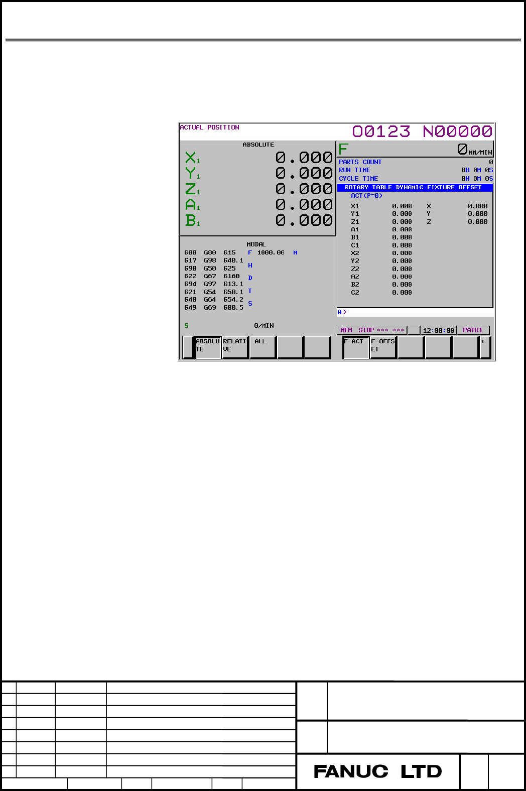
1.2 Fixture offset screen
The fixture offset screen is either a fixture offset (ACT) screen for verifying
the currently selected fixture offset value or a fixture offset screen for setting
and verifying eight fixture offset value sets.
・ Ative Fixture offset screen
・
1. Press the[OFFSET/SETTING]function key
2. Press the continuous menu key sevral times, until The [F-ACT] soft key
appears.
3. Press the [F-ACT] soft key.
The fixture offset (ACT) screen displays.
This screen displays the currently selected fixture offset number (P) and
fixture offset vector.
Contents Summary of Series 30i-MODEL A, Rotary table dynamic fixture offset Additional Manual
- Page 1TECHNICAL REPORT NO. TMN 04/020E Date :Mar .30, 2004 General Manager of Software Laboratory FANUC Series 30i-A Newly additional functions 1. Communicate this report to: Your information only GE Fanuc-N, GE Fanuc-E FANUC Robotics MILACRON Machine tool builder Sales agency End user 2. Summary for Sale
- Page 2FANUC Series30i –A newly additional functions Drawing number Functions 1 A-79227E External Data Input 2 A-79226E One Touch Macro call 3 A-79196E Temporary absolute coordinate setting 4 A-79354E System alarm 5 A-79349E Touch Panel Control 6 A-79253E Distance coded linear scale interface 7 A-79364E Li
- Page 3FANUC Series 30i-MODEL A Rotary table dynamic fixture offset Specifications FANUC Series 30i-MODEL A Title Rotary table dynamic fixture offset Draw A-79359E No. Ed. Date Design Description page 1/15 Date Jan.07.’04 Design. Apprv.
- Page 4GENERAL The rotary table dynamic fixture offset function saves the operator the trouble of resetting the workpiece coordinate system when the rotary table rotates before cutting is started. With this function the operator simply sets the position of a workpiece placed at a certain position on the ro
- Page 51.1 Explanation ・Fixture offset command When a command G54.2Pn is specified, a fixture offset value is calculated from the current rotation angle and the data specified with n, and enable the fixture offset value. If n = 0, the fixture offset value is disabled. ・When a move command is specified for
- Page 6If a machine has two or more rotation axes and the plane of rotation depends on the rotation about another rotation axis, the plane of rotation is set when the angular displacement about the rotation axis is 0. ② Setting the reference angle of the rotation axis and the corresponding reference fixtur
- Page 7n : Fixture offset number (1 to 8) (The current offset is used if n = 0.) m : Axis number (1 to number of controlled axes) NOTE The custom macro option is needed. ③ Reading and writing through the PMC window or open CNC The window function can be used to read/write a custom macro system variable hav
- Page 8O :Rotary table center W :Workpiece origin offset value F0 :Fixture offset value when B=θ0,C=φ0 FA :Fixture offset value (FAX,FAY,FAZ) when B=0,C=0 F :Fixture offset value (FX,FY,FZ) when B=θ,C=φ Then, the following expression is used for fixture offset calculation. FAX cos(− θ 0 ) 0 sin (− θ
- Page 91.2 Fixture offset screen The fixture offset screen is either a fixture offset (ACT) screen for verifying the currently selected fixture offset value or a fixture offset screen for setting and verifying eight fixture offset value sets. ・ Ative Fixture offset screen ・ 1. Press the[OFFSET/SETTING]func
- Page 10・ Fixture offset setting screen 1. Press the[OFFSET/SETTING]function key 2. Press the continuous menu key sevral times, until The [F-OFFSET] soft key appears. 3. Press the [F-ACT] soft key. The fixture offset (ACT) screen displays. The number of groups that are displayed on one screen is fixed 1 to
- Page 111.3 ・Limitation ・Command for suppressing fixture offset calculation If the following commands are specified for the rotation axis in the G54.2 mode, the fixture offset vector is not calculated: Command related to the machine coordinate system: G53 Command specifying a change of the work piece coordi
- Page 121.4 Notes ・When data is modified in G54.2 mode In the G54.2 mode, a change made to the setting of parameter or to the reference fixture offset becomes effective when the next G54.2Pn is specified. ・Movement due to a fixture offset vector change It depends on the current continuous–state code of the
- Page 131.5 Example Parameter Parameter 7580=4 (C–axis) Parameter 7581=1 (X–axis) Parameter 7582=2 (Y–axis) Parameter 7583~7588=0 7575#0(X)=1 (The offset is valid for the X–axis.) 7575#0(Y)=1 (The offset is valid for the Y–axis.) 7570#0=0 (When bit 0 of parameter 7570 is set to 1, the values in square brack
- Page 14Y C C=90° N4 C=180° N5 N3 N2 [N3] X Machine coordinate system zero point Table1.5 (b) Example of fixture offset When G54.2 P1 is specified in the N2 block, the fixture offset vector (0, 10.0) is calculated. The vector is handled in the same way as the offset from the workpiece reference point. The c
- Page 151.6 Parameter #7 #6 #5 #4 #3 #2 #1 #0 7570 CFA FTP [Input type] Parameter input [Data type] bit path FTP Specifies a fixture offset type, as follows: 0: Movement type (movement occurs if the fixture offset changes) 1: Shift type (movement does not occur even if the fixture offset changes) CFA When t
- Page 167585 Specifying linear axis 2 forming a plane to which fixture offset is to be applied ( second set ) 7586 Specifying rotation axis to which fixture offset is to be applied (third set) 7587 Specifying linear axis 1 forming a plane to which fixture offset is to be applied (third set) 7588 Specifying
- Page 171.7 Number Message Description PS5251 There is an error in the G54.2 The fixture offset parameter is incorrect (7580 to 7588). parameter. PS5252 There is an invalid P code The P value for specifying an offset number for the fixture specification in the G54.2 offset is too large. Correct the program.