CZi Sensor (with Serial Interface) Additional Manual Page 7
Additional Manual
Draw.
Title
Na
g
atomo 04.02.16 01
PAGE
7/14
FANUC LTD.
A-72587-0148EN
Descri
p
tionDesi
g
n Date Edit
.
CZi Sensor (with Serial Interface)
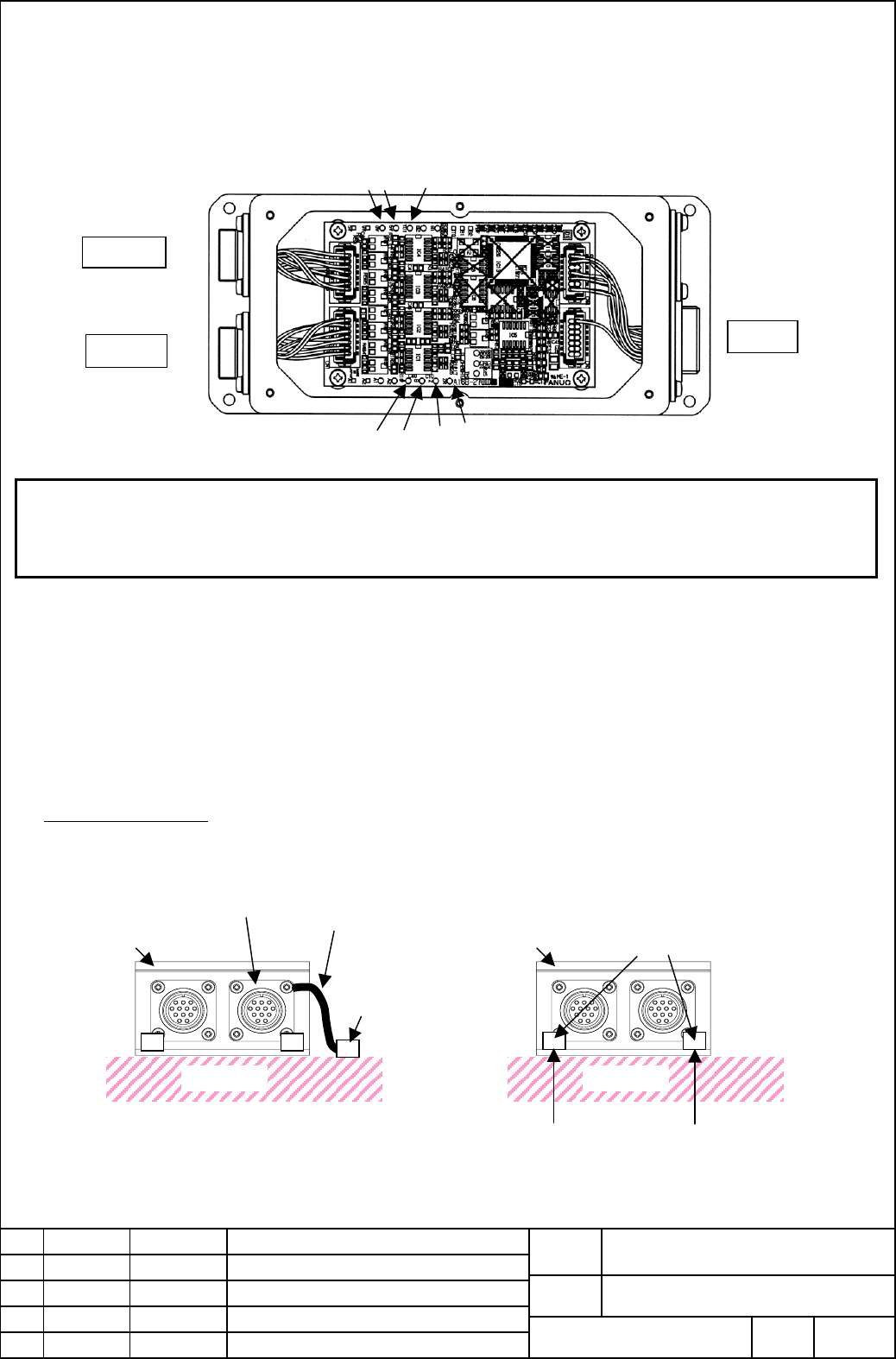
(5).3 In case of checking the output amplitude
・Please refer to the section 3 “electrial specification” in checking the output amplitude.
・Lissajous’ waveform of A /B phase signal is close to a true circle
・In checking the output amplitude without connecting SVM, please connect 5V and 0V check-pin to the power source.
NOTE
・The sensor, the preamplifier, and the detection ring are adjusted by the set. So use them by the set and do not touch the
variable resistance in a preamplifier.
・Sensor side connector part has the marking of "CN1”(black) and “CN2”(Blue)”. When connecting them to the preamplifier,
please check these marks on the connector.
(6) Connecting the preamplifier ground to the machine
The preamplifier should be connected to the grounded machine. Attach the preamplifier box to the machine with the
earth cable using the connector plate screw as shown in the example a) below, or remove the painting of the preamplifier
box in the area that the screw touches directly and fix the screw when attaching the preamplifier box to the machine as
shown in b) below.
T01
A
B
Z
0V
5V
CN1
CN2
To CZi Sensor
CN3
To SVM
(a) Connect the preamplifier to the machine by an
earth cable
Machine
Earth cable
Preamplifier
Screw
Machine
Preamplifier
Screw
(b) Remove the painting of the preamplifier in
the area that the screw touches when attaching
the preamplifier box.
A
rea that the screw touches
Examples of connection
RZ
connector plate
Contents Summary of CZi Sensor (with Serial Interface) Additional Manual
- Page 1CZi Sensor (with Serial Interface) 1.Type of applied technical documents Title CZi Sensor (with Serial Interface) Spec. No./Ver. A-72587-0148EN 2.Summary of change Group Name/Outline New・Add Applicable Correct・Del Date Basic Function Optional Function Unit Maintenance Parts Notice Correction Another
- Page 2CZi Sensor (with Serial Interface) (1) Names and Drawing Numbers Table (1) Names and Drawing Numbers Remarks Accuracy Number Maximum Name Drawing No. Resolution Detection ring (typ.) of teeth speed Inner Outer Function diameter diameter CZi Sensor 1/3600000 5/1000 A860-2141-T411 512 1200min-1 φ82 φ1
- Page 3(4) Outline Drawing (4).1 CZi Sensor 512S This bolt for fixing AB/Z ring. Fastened before shipment A860-2141-T411 For detection ring attachment 6-φ 5.5 drill, sensor P.C.D.φ 92 head Sensor mounting ring sensor head For the sensor Alignment track mounting ring attachment Sectional drawing Cable lengt
- Page 4(4).3 CZi Sensor 1024S This bolt for fixing AB/Z ring. A860-2141-T611 Fastened before shipment For detection ring attachment 6-φ 6.6 drill Sensor head P.C.D.φ 183 Sensor mounting ring Sensor For the sensor head mounting ring attachment Alignment track 4-φ 6.6 drill Sectional drawing of A-A’ P.C.D.φ
- Page 5(5) Mounting method of CZi Sensor (5).1 Mounting the detection ring Prepare a flange on the spindle shaft and fix the detection ring with screws to the spindle axis direction using the through holes on the detection ring. Adjust the detection ring so that the radial eccentricity of the alignment tra
- Page 6(5).2 Mounting the sensor mounting ring The spindle should be so designed that it will construct the clearance fit between the outer diameter of the sensor mounting ring and the fitting part of the spindle as shown in the diagram below (The error in the fitting size may cause the increase of the det
- Page 7(5).3 In case of checking the output amplitude ・Please refer to the section 3 “electrial specification” in checking the output amplitude. ・Lissajous’ waveform of A /B phase signal is close to a true circle ・In checking the output amplitude without connecting SVM, please connect 5V and 0V check-pin t
- Page 8(7) Rotational direction of CZi Sensor The CZi sensor rotates to the forward direction when the detection rings is rotated clockwise from the top side view of the sensor. Forward Please check the rotational derection of the motor by referring to the specification of Syncronous Built-in Motor Dis ser
- Page 9(8) Block diagram of connection (8).1 In case of connecting to SVM ( Position detection usage for the Synchronous Built-in Motor DiS Series) αi series SVM CNC Preamplifier FSSB FANUC Serial I/F CN3 K1 CZi sensor (8).2 In case of connecting to the Separate detector Interface Unit (Separete detector u
- Page 10(9) Specifications of connection (9).1 Cable K1 CZi Sensor(with Serial Interface) SVM preamplifier SS (5) RD (1) (6) *RD (2) (12, 14) 0V (9),(10),(11) ( 9,18, 5V (12),(13),(14) (7) 6V (7) (16) FG (15) 20half-pitch connector HIROSE RM21WTP-15S-( 8) Earth plate ※ 6V line is not connected inside of CZi
- Page 11(9).2 Cable K2 SVM or CZi Sensor(with Serial Interface) Separate Interface Unit SS Preamplifier (1) SD (3) (2) *SD (4) (5) REQ (1) (6) *REQ (2) (12, 14) 0V (9),(10),(11) (9,18, 20) 5V (12),(13),(14) (7) 6V (7) (16) FG (15) 20pin half-pitch connector HIROSE RM21WTP-15S-( 8) Earth plate ※ 6V line is n
- Page 12(9).3 Cable length of K1 and K2 Design the cable length so that the voltage drop in the cable is less than 0.2V. [Example] The voltage drop can be calculated as below when the number of 0V/5V lines are two with each other ,each line resistance is 38.7 Ω/km and the cable length is 10m. (Current consu
- Page 13(10)Setting of parameters The number of feedback pulse per 1 revolution differs along with the teeth number of CZi Sensor(with Serial Interface). Set parameters shown below. (10).1 Series and editions of applicable servo software 90B0/YA 90B1/01 and subsequent editions. (10).2 In case of using CZi S
- Page 14(10).3 In case of using CZi Sensor (with Serial Interface) as Separate Detector (CZi SENSOR1024S) Set parameters as rotary type encoder with FANUC Serial Interface F・FG (Necessary position FB pulses per detector revolution) / 1000000 Position pulses 12500×(reduction ratio from motor to table) Refere