SERIES 21-210i MODEL A Maintenance manual Page 337
Maintenance manual
7. TROUBLESHOOTING
B−63085EN/02
318
When the spindle amplifier does not become normal state immediately
after power is turned on in the serial spindle system, this alarm is
informed.
This alarm does not occur once the system becomes ready including the
spindle system .
This alarm occurs during power on sequence before the system becomes
ready.
After the system becomes ready, serial spindle alarm is issued by alarm
749.
(1)Cable is in poor contact or spindle amplifier power is off.
(2)When display of spindle amplifier shows SU−01or an alarm other than
AL−24 is displayed, power to the NC is turned on.
In this case, this alarm usually occurs when the NC’s power is turned
off while the serial spindle is operating. Turn off the power of serial
spindle once, then turn it on and starts the system.
(3)Combination of hardware is wrong.
(4)When the 2nd spindle is at the state of (1) to (3).
When the 2nd spindle is used, parameter is set as follows :
Bit 4 of parameter no.3701 is 1: No. of serial spindles connected is 2.
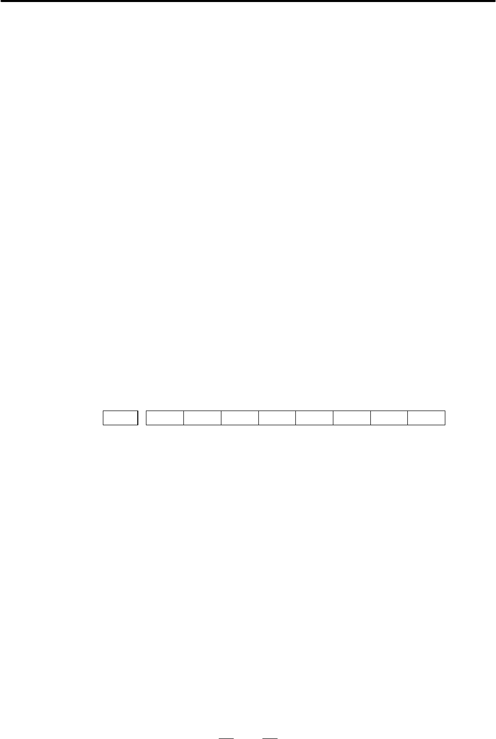
Confirm the details of troubles on diagnostic 409.
#7
0409
#6 #5 #4 #3
SPE
#2
S2E
#1
S1E
#0
SHE
DGN
#0(SHE) 0 : Serial communication module on the CNC side is normal.
1 : Serial communication module was detected to be abnormal on the
CNC side.
#1(S1E) 0 : The serial communication module of the CNC side is normal.
1 : The serial communication module of the CNC side is abnormal.
#2(S2E) 0 : At the start of spindle serial control, the spindle is normal.
1 : At the start of spindle serial control, the spindle is abnormal.
#3(SPE) 0 : In spindle serial control, the serial spindle parameters satisfies the
starting conditions for spindle amplifier.
1 : In spindle serial control, the serial spindle parameters do not satisfy
the starting conditions for spindle amplifier.
7.14
ALARM 750
(SPINDLE SERIAL
LINK CANNOT BE
STARTED)
Points
Causes
Details of Alarms
Contents Summary of SERIES 21-210i MODEL A Maintenance manual
- Page 1FANUC Series 21i−MODEL A FANUC Series 210i−MODEL A MAINTENANCE MANUAL B−63085EN/02 ã FANUC LTD, 1997
- Page 2D No part of this manual may be reproduced in any form. D All specifications and designs are subject to change without notice. In this manual we have tried as much as possible to describe all the various matters. However, we cannot describe all the matters which must not be done, or which cannot be
- Page 3SAFETY PRECAUTIONS This section describes the safety precautions related to the use of CNC units. It is essential that these precautions be observed by users to ensure the safe operation of machines equipped with a CNC unit (all descriptions in this section assume this configuration). CNC maintenanc
- Page 4SAFETY PRECAUTIONS B−63085EN/02 1 DEFINITION OF WARNING, CAUTION, AND NOTE This manual includes safety precautions for protecting the maintenance personnel (herein referred to as the user) and preventing damage to the machine. Precautions are classified into Warnings and Cautions according to their
- Page 5B−63085EN/02 SAFETY PRECAUTIONS 2 WARNINGS RELATED TO CHECK OPERATION WARNING 1. When checking the operation of the machine with the cover removed (1) The user’s clothing could become caught in the spindle or other components, thus presenting a danger of injury. When checking the operation, stand aw
- Page 6SAFETY PRECAUTIONS B−63085EN/02 WARNING 5. Ensure that the specified feedrate is appropriate for the intended operation. Generally, for each machine, there is a maximum allowable feedrate. The appropriate feedrate varies with the intended operation. Refer to the manual provided with the machine to d
- Page 7B−63085EN/02 SAFETY PRECAUTIONS 3 WARNINGS RELATED TO REPLACEMENT WARNING 1. Always turn off the power to the CNC and the main power to the power magnetics cabinet. If only the power to the CNC is turned off, power may continue to be supplied to the serve section. In such a case, replacing a unit ma
- Page 8SAFETY PRECAUTIONS B−63085EN/02 4 WARNINGS RELATED TO PARAMETERS WARNING 1. When machining a workpiece for the first time after modifying a parameter, close the machine cover. Never use the automatic operation function immediately after such a modification. Instead, confirm normal machine operation
- Page 9B−63085EN/02 SAFETY PRECAUTIONS 5 WARNINGS AND NOTES RELATED TO DAILY MAINTENANCE WARNING 1. Memory backup battery replacement When replacing the memory backup batteries, keep the power to the machine (CNC) turned on, and apply an emergency stop to the machine. Because this work is performed with th
- Page 10SAFETY PRECAUTIONS B−63085EN/02 WARNING 2. Absolute pulse coder battery replacement When replacing the memory backup batteries, keep the power to the machine (CNC) turned on, and apply an emergency stop to the machine. Because this work is performed with the power on and the cabinet open, only those
- Page 11B−63085EN/02 SAFETY PRECAUTIONS WARNING 3. Fuse replacement Before replacing a blown fuse, however, it is necessary to locate and remove the cause of the blown fuse. For this reason, only those personnel who have received approved safety and maintenance training may perform this work. When replacing
- Page 12B−63085EN/02 PREFACE PREFACE Description of 1.Display and operation this manual This chapter covers those items, displayed on the screen, that are related to maintenance. A list of all supported operations is also provided at the end of this chapter. 2.Hardware This chapter covers hardware−related i
- Page 13PREFACE B−63085EN/02 Applicable models Pruduct name Abbreviation FANUC Series 21i−TA 21i−TA T series FANUC Series 210i−TA 210i−TA FANUC Series 21i−MA 21i−MA M series FANUC Series 210i−MA 210i−MA NOTE Some function described in this manual may not be applied to some products. For details, refer to th
- Page 14B−63085EN/02 Table of Contents SAFETY PRECAUTIONS . . . . . . . . . . . . . . . . . . . . . . . . . . . . . . . . . . . . . . . . . . . . . . . . . . . . . s−1 PREFACE . . . . . . . . . . . . . . . . . . . . . . . . . . . . . . . . . . . . . . . . . . . . . . . . . . . . . . . . . . . . . . . . . .
- Page 15TABLE OF CONTENTS B−63085EN/02 1.11 OPERATING MONITOR . . . . . . . . . . . . . . . . . . . . . . . . . . . . . . . . . . . . . . . . . . . . . . . . . . . . . . . . . . . 68 1.11.1 Display Method . . . . . . . . . . . . . . . . . . . . . . . . . . . . . . . . . . . . . . . . . . . . . . . . . . . .
- Page 16B−63085EN/02 TABLE OF CONTENTS 2.10 REPLACING FAN MOTORS . . . . . . . . . . . . . . . . . . . . . . . . . . . . . . . . . . . . . . . . . . . . . . . . . . . . . . 146 2.11 REPLACING LCD BACKLIGHT . . . . . . . . . . . . . . . . . . . . . . . . . . . . . . . . . . . . . . . . . . . . . . . . . . .
- Page 17TABLE OF CONTENTS B−63085EN/02 3.8 DATA INPUT/OUTPUT USING A MEMORY CARD . . . . . . . . . . . . . . . . . . . . . . . . . . . . . . . . . . . 205 3.9 OUTPUTTING/INPUTTING MACHINING PROGRAMS . . . . . . . . . . . . . . . . . . . . . . . . . . . . . . . 215 3.9.1 Outputting Machining Programs . . . .
- Page 18B−63085EN/02 TABLE OF CONTENTS 6.2 AC SPINDLE (ANALOG INTERFACE) . . . . . . . . . . . . . . . . . . . . . . . . . . . . . . . . . . . . . . . . . . . . . 274 6.2.1 Outline of Spindle Control . . . . . . . . . . . . . . . . . . . . . . . . . . . . . . . . . . . . . . . . . . . . . . . . . . . . 274
- Page 19TABLE OF CONTENTS B−63085EN/02 C. BOOT SYSTEM . . . . . . . . . . . . . . . . . . . . . . . . . . . . . . . . . . . . . . . . . . . . . . . . . . . . . . . . . . . 375 C.1 OVERVIEW . . . . . . . . . . . . . . . . . . . . . . . . . . . . . . . . . . . . . . . . . . . . . . . . . . . . . . . . . . . .
- Page 20B−63085EN/02 1. DISPLAY AND OPERATION 1 DISPLAY AND OPERATION This chapter describes how to display various screens by the function keys. The screens used for maintenance are respectively displayed. 1.1 FUNCTION KEYS AND SOFT KEYS . . . . . . . . . . . . . 2 1.2 SCREEN DISPLAYED IMMEDIATELY AFTER PO
- Page 211. DISPLAY AND OPERATION B−63085EN/02 1.1 Operations and soft key display staturs for each function key are described below: FUNCTION KEYS AND SOFT KEYS 1.1.1 To display a more detailed screen, press a function key followed by a soft Soft Keys key. Soft keys are also used for actual operations. The
- Page 22B−63085EN/02 1. DISPLAY AND OPERATION POSITION SCREEN Soft key transition triggered by the function key POS POS Absolute coordinate display [ABS] [(OPRT)] [PTSPRE] [EXEC] [RUNPRE] [EXEC] Relative coordinate display [REL] [(OPRT)] (Axis or numeral) [PRESET] [ORIGIN] [ALLEXE] [Axis name] [EXEC] [PTSPR
- Page 231. DISPLAY AND OPERATION B−63085EN/02 PROGRAM SCREEN Soft key transition triggered by the function key PROG in the MEM mode 1/2 PROG Program display screen [PRGRM] [(OPRT)] [BG−EDT] See “When the soft key [BG−EDT] is pressed” [O number] [O SRH] (1) [N number] [N SRH] [REWIND] [P TYPE] [Q TYPE] [F SR
- Page 24B−63085EN/02 1. DISPLAY AND OPERATION 2/2 (2) [FL.SDL] [PRGRM] Return to (1) (Program display) File directory display screen [DIR] [(OPRT)] [SELECT] [File No. ] [F SET] [EXEC] Schedule operation display screen [SCHDUL] [(OPRT)] [CLEAR] [CAN] [EXEC] (Schedule data) [INPUT] 5
- Page 251. DISPLAY AND OPERATION B−63085EN/02 PROGRAM SCREEN Soft key transition triggered by the function key PROG in the EDIT mode 1/2 PROG Program display [PRGRM] [(OPRT)] [BG−EDT] See “When the soft key [BG−EDT] is pressed” (O number) [O SRH] (Address) [SRH¯] (Address) [SRH] [REWIND] [F SRH] [CAN] (N n
- Page 26B−63085EN/02 1. DISPLAY AND OPERATION 2/2 (1) Program directory display [LIB] [(OPRT)] [BG−EDT] See “When the soft key [BG−EDT] is pressed” (O number) [O SRH] Return to the program [READ] [CHAIN] [STOP] [CAN] (O number) [EXEC] [PUNCH] [STOP] [CAN] (O number) [EXEC] Floppy directory display [FLOPPY]
- Page 271. DISPLAY AND OPERATION B−63085EN/02 PROGRAM SCREEN Soft key transition triggered by the function key PROG in the MDI mode PROG Program display [PRGRM] [(OPRT)] [BG−EDT] See “When the soft key [BG−EDT] is pressed” Program input screen [MDI] [(OPRT)] [BG−EDT] See “When the soft key [BG−EDT] is press
- Page 28B−63085EN/02 1. DISPLAY AND OPERATION PROGRAM SCREEN Soft key transition triggered by the function key PROG in the HNDL, JOG, or REF mode PROG Program display [PRGRM] [(OPRT)] [BG−EDT] See “When the soft key [BG−EDT] is pressed” Current block display screen [CURRNT] [(OPRT)] [BG−EDT] See “When the s
- Page 291. DISPLAY AND OPERATION B−63085EN/02 PROG PROGRAM SCREEN Soft key transition triggered by the function key (When the soft key [BG−EDT] is pressed in all modes) 1/2 PROG Program display [PRGRM] [(OPRT)] [BG−END] (O number) [O SRH] (Address) [SRH¯] (Address) [SRH] [REWIND] [F SRH] [CAN] (N number) [
- Page 30B−63085EN/02 1. DISPLAY AND OPERATION 2/2 (1) Program directory display [LIB] [(OPRT)] [BG−EDT] (O number) [O SRH] Return to the program [READ] [CHAIN] [STOP] [CAN] (O number) [EXEC] [PUNCH] [STOP] [CAN] (O number) [EXEC] Floppy directory display [FLOPPY] [PRGRM] Return to the program [DIR] [(OPRT)]
- Page 311. DISPLAY AND OPERATION B−63085EN/02 Soft key transition triggered by the OFFSET/SETTING SCREEN (T series) function key OFFSET SETTING 1/2 OFFSET SETTING Tool offset screen [OFFSET] [WEAR] [(OPRT)] (Number) [NO SRH] [GEOM] (Axis name and numeral) [MEASUR] (Axis name) [INP.C.] (Numeral) [+INPUT] (Nu
- Page 32B−63085EN/02 1. DISPLAY AND OPERATION 2/2 (1) Pattern data input screen [MENU] [(OPRT)] (Number) [SELECT] Software operator’s panel screen [OPR] Tool life management setting screen [TOOLLF] [(OPRT)] (Number) [NO SRH] [CLEAR] [CAN] [EXEC] (Numeral) [INPUT] Y axis tool offset screen [OFST.2] [WEAR] [(
- Page 331. DISPLAY AND OPERATION B−63085EN/02 Soft key transition triggered by the OFFSET/SETTING SCREEN (M series) function key OFFSET SETTING 1/2 OFFSET SETTING Tool offset screen [OFFSET] [(OPRT)] (Number) [NO SRH] (Axis name) [INP.C.] (Numeral) [+INPUT] (Numeral) [INPUT] [CLEAR] [ALL] [WEAR] [GEOM] [REA
- Page 34B−63085EN/02 1. DISPLAY AND OPERATION 2/2 (1) Pattern data input screen [MENU] [(OPRT)] (Number) [SELECT] Software operator’s panel screen [OPR] Tool life management setting screen [TOOLLF] [(OPRT)] (Number) [NO SRH] [CLEAR] [CAN] [EXEC] (Numeral) [INPUT] 15
- Page 351. DISPLAY AND OPERATION B−63085EN/02 SYSTEM SCREEN Soft key transition triggered by the function key SYSTEM 1/3 SYSTEM Parameter screen [PARAM] [(OPRT)] (Number) [NO SRH] [ON:1] [OFF:0] (Numeral) [+INPUT] (Numeral) [INPUT] [READ] [CAN] [EXEC] [PUNCH] [CAN] [EXEC] Diagnosis screen [DGNOS] [(OPRT)] (
- Page 36B−63085EN/02 1. DISPLAY AND OPERATION (1) (2) (3) 2/3 [DUMP] [SEARCH] [BYTE] [WORD] [D.WORD] [DRARA]/[NDPARA] [PMCDGN] [TITLE] [STATUS] [SEARCH] [ALARM] [TRACE] [T.DISP]/[TRCPRM] [EXEC] [PMCPRM] [TIMER] [COUNTR] [KEEPRL] [DATA] [G.DATA] [C.DATA] [G.CONT] [G−SRCH] [NO.SRH] [SEARCH] [INIT] [SETTING] [
- Page 371. DISPLAY AND OPERATION B−63085EN/02 (4) 3/3 Servo parameter screen [SV.PRM] [SV.SET] [ON:1] [(OPRT)] [SV.TUN] [OFF:0] (Numeral) [INPUT] [TRACE] [SV.TRC] [(OPRT)] [TRNSF] Spindle parameter screen [SP.PRM] [SP.SET] [ON:1] [(OPRT)] [SP.TUN] [OFF:0] [SP.MON] [INPUT] Waveform diagnosis screen [W.DGNS]
- Page 38B−63085EN/02 1. DISPLAY AND OPERATION MESSAGE SCREEN Soft key transition triggered by the function key MESSAGE MESSAGE Alarm display screen [ALARM] Message display screen [MSG] Alarm history screen [HISTRY] [(OPRT)] [CLEAR] HELP SCREEN Soft key transition triggered by the function key HELP HELP Alar
- Page 391. DISPLAY AND OPERATION B−63085EN/02 GRAPHIC SCREEN (T series) Soft key transition triggered by the function key GRAPH Tool path graphics Mode 0 GRAPH Tool path graphics [G.PRM] [(OPRT)] [NORMAL] [GRAPH] [(OPRT)] [HEAD] [ERASE] [PROCES] [EXEC] [STOP] [ZOOM] [(OPRT)] [ACT] [HI/LO] GRAPHIC SCREEN (M
- Page 40B−63085EN/02 1. DISPLAY AND OPERATION 1.2 SCREEN DISPLAYED IMMEDIATELY AFTER POWER IS TURNED ON 1.2.1 Types of PCBs mounted on the slots are displayed. Slot Status Display If a hardware trouble or an incorrect mounting is found, this screen is displayed. D Slot state screen SLOT CONFIGURATION DISPLA
- Page 411. DISPLAY AND OPERATION B−63085EN/02 1.2.2 Setting Module Screen END : Setting DDF1−01 completed SLOT 01 (3046) : END Space : SLOT 02 (0050) : Setting incom- pleted Module ID Slot number 1.2.3 Configuration Display of Software DDF1−01 CNC control software SERVO : 9090−01 Digital servo SUB : xxxx−xx
- Page 42B−63085EN/02 1. DISPLAY AND OPERATION 1.3 After the system has been installed correctly, you can find the PCBs installed and the softwares integrated on the system configuration screen. SYSTEM CONFIGURATION SCREEN 1.3.1 (1) Press SYSTEM key. Display Method (2) Press soft key [system],then the system
- Page 431. DISPLAY AND OPERATION B−63085EN/02 1.3.3 Kind of software Software Configuration Software series Screen SYSTEM CONFIG (SOFTWARE) 01234 N12345 PAGE:02 SYSTEM DDF1 0001 Software version BASIC+OPTION−A1 Software SERVO 9090 0001 configuration PMC(SYS) 406A 0001 406B 0001 4099 0001 PMC(LAD) FS21 0001
- Page 44B−63085EN/02 1. DISPLAY AND OPERATION 1.4 ALARM HISTORY SCREEN 1.4.1 Alarms generated in the NC are recorded. The latest 25 alarms generated General are recorded. The 26th and former alarms are deleted. 1.4.2 (1) Press MESSAGE key . Screen Display (2) Press soft key [HISTRY] and an alarm history scr
- Page 451. DISPLAY AND OPERATION B−63085EN/02 1.5 This function enables the saving of external operator messages as a record. EXTERNAL The record can be viewed on the external operator message history screen. OPERATOR MESSAGES RECORD 1.5.1 (1) Press the MESSAGE function key. Screen Display (2) Press the rig
- Page 46B−63085EN/02 1. DISPLAY AND OPERATION 1.5.3 Parameter #7 #6 #5 #4 #3 #2 #1 #0 3113 MS1 MS0 MHC #0 (MHC) The records of an external operator message: 0 : Cannot be erased. 1 : Can be erased. #6, #7 (MS0,MS1) These bits set the number of characters to be retained in each record of an external operator
- Page 471. DISPLAY AND OPERATION B−63085EN/02 1.6 This function displays the key and signal operations performed by the operator upon the occurrence of a fault or the output of an alarm, together OPERATION with the corresponding alarms. HISTORY This function records the following data: (1) MDI key operation
- Page 48B−63085EN/02 1. DISPLAY AND OPERATION 1.6.2 Screen Display D Displaying the operation (1) Press the SYSTEM function key. history (2) Press the continue menu key [ ]. The [OPEHIS] [(OPRT)] soft key are displayed. (3) Press the [OPEHIS] soft key twice. The operation history screen is displayed. OPERAT
- Page 491. DISPLAY AND OPERATION B−63085EN/02 Data displayed on the operation history screen (1) MDI keys Address and numeric keys are displayed after a single space. Soft keys are displayed in square brackets ([]). Other keys (RESET/INPUT, for example) are displayed in angle brackets (<>). A key pressed at
- Page 50B−63085EN/02 1. DISPLAY AND OPERATION Mode selection signals and rapid traverse override signals are displayed as indicated below: Input signal Name displayed MD1 MD2 MD4 REF DNC1 0 0 0 0 0 MDI 1 0 0 0 0 MEM 1 0 0 0 1 RMT 0 1 0 0 0 NOMODE 1 1 0 0 0 EDT 0 0 1 0 0 H/INC 1 0 1 0 0 JOG 1 0 1 1 0 REF 0 1
- Page 511. DISPLAY AND OPERATION B−63085EN/02 1) The power−on time is displayed as shown below: 97/01/20 ==== Year/Month/Day 09:15:30 ==== Hour:Minute:Second 2) The power−off time and the time when an NC alarm occurred are displayed in reverse video. 97/01/20 ==== Year/Month/Day 09:15:30 ==== Hour:Minute:Se
- Page 52B−63085EN/02 1. DISPLAY AND OPERATION 1.6.3 (1) On the operation history signal selection screen, press the [(OPE)] soft Setting the Input Signal key. or Output Signal to be OP_HIS SIGNAL SELECT O1000 N02000 Recorded in the Operation History No. ADDRES SIGNAL No. ADDRES SIGNAL 01 G0004 00000010 11 *
- Page 531. DISPLAY AND OPERATION B−63085EN/02 (8) Pressing the return menu key [ ] causes the [OPEHIS] (OPE) soft key to be displayed again. D Input signals and output signals to be recorded in the history NOTE 1 A cross (´) indicates that a signal will not be recorded. Also, any signal for which an address
- Page 54B−63085EN/02 1. DISPLAY AND OPERATION #7 #6 #5 #4 #3 #2 #1 #0 G020 f f f f f f f f G042 f f f f f f f f G043 f ´ f ´ ´ f f f G044 f f f f f f MLK BDT1 G045 BDT9 BDT8 BDT7 BDT6 BDT5 BDT4 BDT3 BDT2 G046 DRN KEY4 KEY3 KEY2 KEY1 f SBK f G047 f f f f f f f f G060 f f f f f f f f G061 f f f f f f f RGTA G
- Page 551. DISPLAY AND OPERATION B−63085EN/02 #7 #6 #5 #4 #3 #2 #1 #0 G115 f f f f f f f f G116 f f f f *−L4 *−L3 *−L2 *−L1 G117 f f f f f f f f G118 f f f f *+ED4 *+ED3 *+ED2 *+ED1 G119 f f f f f f f f G120 f f f f *−ED4 *−ED3 *−ED2 *−ED1 G121 f f f f f f f f G125 f f f f f f f f G126 f f f f SVF4 SVF3 SVF
- Page 56B−63085EN/02 1. DISPLAY AND OPERATION 1.6.4 Recorded data can be output to an input/output unit connected via a Inputting and reader/punch interface. An output record can be input from the input/output unit. Outputting the Set the input/output unit to be used in setting parameters No. 0020 and Opera
- Page 571. DISPLAY AND OPERATION B−63085EN/02 1) Header T 0 C O P E R A T I O N H I S T O R Y ; C: Data word 2) MDI/soft key T 5 0 P 0 to 1 H * * ; P0: Usually P1: At power−on H **: Key code (See the following table.) 3) Signal T 5 1 P 0 to 6 N 0 to 255 H * * , * * ; New data Old data P0: X0000 and above P2
- Page 58B−63085EN/02 1. DISPLAY AND OPERATION 4) Alarm T 5 2 P 0 to 10 N * * * * ; P0: P/S No. 100 P1: P/S No. 000 P2: P/S No. 101 P3: P/S No. 0001 to 254 P4: Overtravel alarm P5: Overheat alarm P6: Servo alarm P7: System alarm P8: APC alarm P9: Spindle alarm P10: P/S alarm No. 5000 to 5999 P15: External al
- Page 591. DISPLAY AND OPERATION B−63085EN/02 Key codes (MDI/soft key) (00H to 7FH) 0 1 2 3 4 5 6 7 0 Space 0 @ P 1 ! 1 A Q 2 ² 2 B R 3 # 3 C S 4 $ 4 D T 5 % 5 E U 6 & 6 F V 7 ’ 7 G W 8 ( 8 H X 9 ) 9 I Y A ; * : J Z (EOB) B + K [ C ’ < L ¥ D − = M ] E . > N F / ? O − 40
- Page 60B−63085EN/02 1. DISPLAY AND OPERATION (80H to FFH) 8 9 A B C D E F 0 Reset F0 * * 1 MMC F1 * * 2 CNC F2 * * 3 F3 * 4 Shift Insert F4 * * 5 Delete F5 * * 6 CAN Alter F6 * * 7 F7 * 8 Cur® Input POS F8 * * * * 9 Cur¬ PROG F9 * * * A Cur¯ Help OFFSET * * SETTING * B Cur SYSTEM * * C MESSAGE * D CUSTOM
- Page 611. DISPLAY AND OPERATION B−63085EN/02 1.6.5 (1) While the operation history screen is displayed, no information can be Notes recorded to the history. (2) An input signal having an on/off width of up to 16 msec is not recorded in the history. Some signals are not recorded in the history. See Appendix
- Page 62B−63085EN/02 1. DISPLAY AND OPERATION 1.7 HELP FUNCTION 1.7.1 The help function displays alarm information, operation method and a General table of contents for parameters. This function is used as a handbook. 1.7.2 Press HELP key on any screen other than PMC screen, then a help screen Display Metho
- Page 631. DISPLAY AND OPERATION B−63085EN/02 D Help for operation (1) Press [2 OPR], then a menu for operation method is displayed. HELP (OPERATION METHOD) O1234 N12345 1. PROGRAM EDIT 2. SEARCH 3. RESET 4. DATA INPUT WITH MDI 5. DATA INPUT WITH TAPE 6. OUTPUT 7. INPUT WITH FANUC CASSETTE 8. OUTPUT WITH FA
- Page 64B−63085EN/02 1. DISPLAY AND OPERATION 1.8 DISPLAYING DIAGNOSTIC PAGE 1.8.1 (1) Press SYSTEM key. Displaying Diagnostic (2) Press soft key [DGNOS], then a diagnostic screen is displayed. Page 1.8.2 Contents Displayed D Causes when the 000 WAITING FOR FIN SIGNAL An auxiliary function is being machine
- Page 651. DISPLAY AND OPERATION B−63085EN/02 D Cause of the cycle start LED turned off 020 CUT SPEED UP/DOWN 1 0 0 0 1 0 0 021 RESET BUTTON ON 022 RESET AND REWIND ON 0 0 1 0 0 0 0 023 EMERGENCY STOP ON 0 0 0 1 0 0 0 024 RESET ON 1 0 0 0 0 0 0 025 STOP MOTION OR DWELL 1 1 1 1 0 0 0 1 1 1 1 1 1 0 Input of e
- Page 66B−63085EN/02 1. DISPLAY AND OPERATION D Details of digital servo alarm #7 #6 #5 #4 #3 #2 #1 #0 DGN 0200 OVL LV OVC HCA HVA DCA FBA OFA #0(OFA): Overflow alarm #1(FBA): Disconnection alarm #2(DCA): Discharge alarm #3(HVA): Overvoltage alarm #4(HCA): Abnormal current alarm #5(OVC): Over current alarm
- Page 671. DISPLAY AND OPERATION B−63085EN/02 D Position error amount DGN 0300 Position error of an axis in detection unit Feed rate [mm/min] 1 Position error= ´ 60×servo loop gain [1/sec] Detection unit D Machine position DGN 0301 Distance from reference position of an axis in detection unit D Reference po
- Page 68B−63085EN/02 1. DISPLAY AND OPERATION D Diagnostic data related to the Inductosyn absolute position detector DGN 380 Difference between the absolute position of the motor and offset data M (absolute position of the motor) − S (offset data) l(pitch interval) The remainder resulting from the division
- Page 691. DISPLAY AND OPERATION B−63085EN/02 #7 #6 #5 #4 #3 #2 #1 #0 DGN 0408 SSA SCA CME CER SNE FRE CRE #0 (CRE): A CRC error occurred. (Warning) #1 (FRE): A framing error occurred. (Warning) #2 (SNE): The transmission/reception target is invalid. #3 (CER): An error occurred during reception. #4 (CME): N
- Page 70B−63085EN/02 1. DISPLAY AND OPERATION DGN 0420 Feedback information of 2nd spindle position coder D Diagnostic data related to rigid tapping DGN 450 Spindle position error during rigid tapping [Data type] Word [Unit of data] Detection units DGN 451 Spindle distribution during rigid tapping [Data typ
- Page 711. DISPLAY AND OPERATION B−63085EN/02 D State of remote buffer (protocol A) DGN 0500 Send command 1: SYN 2: RDY 3: RST 4: ALM 5: SAT 6: GTD 7: RTY 8: SDI DGN 0501 Receive command 1: SYN 2: RDY 3: ARS 4: AAL 5: CLB 6: SET 7: DAT 8: EOD 9: WAT 10: RTY 11:RDI 12: SDO DGN 0502 State of remote buffer 0:
- Page 72B−63085EN/02 1. DISPLAY AND OPERATION D Diagnostic data related to a small−diameter peck drilling cycle (M series only) DGN 520 Total number of retractions during cutting after G83 is specified Executing the G83 command clears the value to zero. DGN 521 Total number of retractions made by receiving
- Page 731. DISPLAY AND OPERATION B−63085EN/02 D Diagnostic data related to the dual position feedback function 0550 Closed loop error [Data type] 2−word axis [Unit of data] Detection units [Valid data range] −99999999 to +99999999 0551 Semi−closed loop error [Data type] 2−word axis [Unit of data] Detection
- Page 74B−63085EN/02 1. DISPLAY AND OPERATION 1.9 CNC STATUS ACTUAL POSITION (ABSOLUTE) O1000 N00010 DISPLAY X 217.940 Y 363.233 Z 0.000 PART COUNT 5 RUN TIME 0H15M CYCLE TIME 0H 0M38S ACT.F 3000MM/M S 0 T0000 MEM STRT MTN *** 09:06:35 [ ABS ] [ REL ] [ ALL ] [ HNDL ] [(OPRT)] MEM STRT MTN *** ALM/BAT (Alar
- Page 751. DISPLAY AND OPERATION B−63085EN/02 1.10 Tuning becomes easier by graphically displaying servo error amount and torque command, etc. (Graphic option is required). WAVEFORM DIAGNOSTIC The following two types of waveform diagnosis functions are supported: FUNCTION (1) One−shot type The one−shot type
- Page 76B−63085EN/02 1. DISPLAY AND OPERATION 1.10.2 1. Press the SYSTEM key to display a system screen such as aparameter. Waveform Diagnostic Parameter Screen 2. Press the continuous menu key several times, and the soft key [W.DGNS] is displayed. 3. Press [W.DGNS], then the parameter screen for the wavefo
- Page 771. DISPLAY AND OPERATION B−63085EN/02 (4) Data number: The table below lists the numbers of the data items for which a waveform can be displayed (n = 1 to 4). Data No. Description Units 00 Does not display a waveform. − 0n Servo error (8 ms) for the n−th axis (positional devi- Pulses ation) (detecti
- Page 78B−63085EN/02 1. DISPLAY AND OPERATION D Waveform diagnosis (1) Display start condition parameters (storage 100 : Draws a waveform for the stored data. type) (2) Sampling period: Invalid (3) Trigger: Invalid (4) Data number: The table below lists the numbers of the data items for which a waveform can
- Page 791. DISPLAY AND OPERATION B−63085EN/02 1.10.3 1. Press soft key [W.GRPH], then graph of waveform diagnosis is Graphic of Wave displayed. Diagnosis Data WAVE DIAGNOSE (GRAPHIC) CH1 CH2 1.0 1.0 0.5 0.5 0 0 −0. −0. 5 5 −1. −1. 0 0 [START] [TIME→] [←TIME] [H−DOBL] [H−HALF] 2. Press soft key [(OPRT)], the
- Page 80B−63085EN/02 1. DISPLAY AND OPERATION Pressing the [SATART] soft key starts data sampling. While sampling is being performed, SAMPLING blinks at the top of the screen. Once data sampling has been completed, a waveform is automatically displayed. WAVE DIAGNOS. (GRAPHIC) O1234 N12345 CH1 CH2 EDIT ****
- Page 811. DISPLAY AND OPERATION B−63085EN/02 1.10.4 (1) Press the SYSTEM function key. Pressing the menu continuation key [ ] Data Sampling for displays the [W.DGNS] soft key. Press this soft key to display the Storage Type WAVE DIAGNOS. (PARAMETER) screen. Waveform Diagnosis (2) Press the [W.MEM] soft key
- Page 82B−63085EN/02 1. DISPLAY AND OPERATION CAUTION 1 Data items for which ***** is displayed cannot be set. 2 To change the sampling axes, enter new axis names then press the [SELECT] soft key. Pressing the [SLELCT] soft key without entering an axis name results in no sampling axis being set. 3 If the sa
- Page 831. DISPLAY AND OPERATION B−63085EN/02 1.10.5 Waveform diagnosis data of servo alarm format can be output to an I/O Outputting Waveform device, as follows: Diagnosis Data 1) Select EDIT mode. (Storage Type) 2) Press the SYSTEM key, then display the WAVE DIAGNOS. (MEMORY) screen. 3) Press the [W.MEM],
- Page 84B−63085EN/02 1. DISPLAY AND OPERATION D Directory display The directory in the cassette or card is displayed by means of the following procedure: 1) Select EDIT mode. 2) Press the PROG function key to select the program screen. 3) Press the continuous menu key , then press [FLOPPY]. 4) Press page ke
- Page 851. DISPLAY AND OPERATION B−63085EN/02 D Output format In the servo alarm format, the header, date and time, selected axes, and waveform diagnosis data are output in this order. Data items are identified by nine identifier words. Output data other than the identifier words varies with the data type.
- Page 86B−63085EN/02 1. DISPLAY AND OPERATION 4) Waveform diagnosis data T 6 0 D * * , * * , * * , ~ * * , T 6 1 D * * , * * , * * , ~ * * , T 6 2 D * * , * * , * * , ~ * * , T 6 3 D * * , * * , * * , ~ * * , T 6 4 D * * , * * , * * , ~ * * , T 6 5 D * * , * * , * * , ~ * * , D *..*: Waveform diagnosis data
- Page 871. DISPLAY AND OPERATION B−63085EN/02 1.11 Load meter of the servo axis and the serial spindle and the speed meter can be displayed. OPERATING MONITOR 1.11.1 1. Set a parameter to display operating monitor. (Bit 5 (OPM) of Display Method parameter No.3111) 2. Press the POS key to display the positio
- Page 88B−63085EN/02 1. DISPLAY AND OPERATION 1.11.2 Parameters #7 #6 #5 #4 #3 #2 #1 #0 3111 OPS OPM [Data type] Bit #5(OPM) Operating monitor display is: 0 : Disabled 1 : Enabled #6(OPS) The speed meter on the operating monitor screen displays: 0 : Spindle motor speed 1 : Spindle speed 3151 Axis number for
- Page 891. DISPLAY AND OPERATION B−63085EN/02 1.12 LIST OF OPERATIONS Reset Data Param- Func- protec- Function eter Mode tion Operation tion write=1 button key Resetting run hour [(OPRT)] [RUNPRE]®[EXEC] − POS Resetting no. of [(OPRT)] [PTSPRE]®[EXEC] machined parts − POS Resetting OT alarm At Pow- er ON −
- Page 90B−63085EN/02 1. DISPLAY AND OPERATION Input/Output with FANUC Cassette Data Param- Func- protec- Function eter Mode tion Operation tion write=1 button key Heading a file EDIT PROG N ®File no.®[ ]®[F SRH]®[EXEC] Deleting a file OFF EDIT PROG N ®File no.®[ ]®[DELETE®[EXEC] Collating a program EDIT PRO
- Page 911. DISPLAY AND OPERATION B−63085EN/02 Output to FANUC Cassette Data Param- Func- protec- Function eter Mode tion Operation tion write=1 button key [(OPRT)]®[ ]®[PUNCH]®[EXEC] SYSTEM Output of EDIT parameter (PA- RAM) [ ]®[I/O]®(CANNEL NO) 1 INPUT ®(DEVICE Output of PMC SYSTEM EDIT NAME) [FDCAS] ®(KI
- Page 92B−63085EN/02 1. DISPLAY AND OPERATION Edit Data Param- Func- protec- Function eter Mode tion Operation tion write=1 button key Display of memory [LIB] EDIT PROG capacity used Deleting all OFF programs EDIT PROG O ®−9999® DELETE OFF Deleting a program EDIT PROG O ®Program no.® DELETE Deleting several
- Page 931. DISPLAY AND OPERATION B−63085EN/02 Clear Data Param- Func- prote- Function eter Mode tion Operation ction write=1 key key Memory all clear At M/T : RESET AND DELETE power ON Loader is controlled : CAN AND 5 Parameter/offset clear M/T : RESET At f Power ON Loader is controlled : RESET AND 5 (Param
- Page 94B−63085EN/02 1. DISPLAY AND OPERATION 1.13 WARNING SCREEN DISPLAYED WHEN AN OPTION IS CHANGED D Warning screen This CNC displays a warning screen when the configuration of the options using the SRAM area is changed. The data for the function indicated on the screen is cleared the next time the syste
- Page 951. DISPLAY AND OPERATION B−63085EN/02 D Allocation error screen When an option which uses the SRAM area is added, the system software may require more SRAM than is currently installed in the system. In this case, an allocation error screen appears the first time the system is turned on after the add
- Page 96B−63085EN/02 1. DISPLAY AND OPERATION 1.14 System software can be replaced only with compatible system software. Otherwise, the first time the CNC is turned on after the system software WARNING SCREEN is replaced, the following screen will be displayed and the system will not DISPLAYED WHEN be activ
- Page 971. DISPLAY AND OPERATION B−63085EN/02 1.15 The maintenance information screen is provided to record the history of maintenance performed by a service person of FANUC or machine tool MAINTENANCE builder. INFORMATION The screen has the following features: SCREEN D MDI alphabetical input is allowed. D
- Page 98B−63085EN/02 1. DISPLAY AND OPERATION A02B−0247−J841 : 1 A02B−0247−J850 : 1 A02B−0247−J853 : 1 A02B−0247−J873 : 1 A02B−0247−J876 : 1 A02B−0247−J888 : 1 A02B−0247−J890 : 1 A02B−0247−J894 : 1 A02B−0247−J900 : 1 A02B−0247−J911 : 1 A02B−0247−J926 : 1 A02B−0247−J931 : 1 A02B−0247−J935 : 1 A02B−0247−J937
- Page 991. DISPLAY AND OPERATION B−63085EN/02 1.15.1 Screen Display and Operation D Screen display 1. Press the SYSTEM function key. 2. Press the continuous menu key several times. [M−INFO] soft key appears. 3. Press the [M−INFO] soft key. The maintenance information screen appears. When selected, the maint
- Page 100B−63085EN/02 1. DISPLAY AND OPERATION D Screen operation The maintenance information screen has view mode and edit mode, which are selected by pressing the [END] or [EDIT] soft key. Initially, view mode is selected. To start editing, select edit mode by pressing the [(OPRT)] and [EDIT] keys. When th
- Page 1011. DISPLAY AND OPERATION B−63085EN/02 (1) View mode Edit Jump (2) (5) (2) Edit mode END I/O ALLDEL Jump (3) (4) (6) (5) (3) Edit saving MAINTE- NANCE IGNORE CANCEL (1) (1) (2) (4) I/O READ PUNCH CANCEL (6) (6) (2) (5) Jump BEGIN- END CANCEL ING (1) (2) (1) (2) (1) (2) (6) Execution EXEC CANCEL (2) (
- Page 102B−63085EN/02 1. DISPLAY AND OPERATION 1.15.2 The maintenance information can be read and punched. Maintenance When the maintenance information is input from or output to a memory card, a file name MAINTINF.DAT is used. Information (1) Format Input/Output %% Data (2) Reading When a MAINTINF.DAT file
- Page 1031. DISPLAY AND OPERATION B−63085EN/02 1.16 When VGA screen display is selected (NVG bit (bit 7 of parameter 3119) is set to 0), the color scheme of the VGA screen can be set on the color COLOR SETTING setting screen. SCREEN 1.16.1 1. Press the SYSTEM function key. Screen Display 2. Press the continu
- Page 104B−63085EN/02 1. DISPLAY AND OPERATION 4. Press the [LIGHT] or [DARK] operation soft key to change the luminance of the selected color element. D Storing colors A specified color palette value can be stored. (color palette values) STORE CALL COLOR1 COLOR2 COLOR3 + 1. Select a desired storage area by
- Page 1051. DISPLAY AND OPERATION B−63085EN/02 1.16.3 Parameters #7 #6 #5 #4 #3 #2 #1 #0 3119 NVG [Data type] Bit NVG When a color display unit is used, the VGA screen display is: 0 : Selected. 1 : Not selected. (Conventional display) 6561 Standard color data of graphic color 1 6562 Standard color data of gr
- Page 106B−63085EN/02 1. DISPLAY AND OPERATION 6590 Standard color data of text color 10 6591 Standard color data of text color 11 6592 Standard color data of text color 12 6593 Standard color data of text color 13 6594 Standard color data of text color 14 6595 Standard color data of text color 15 [Data type
- Page 1071. DISPLAY AND OPERATION B−63085EN/02 1.17 The LCD screen display appears dim at low ambient temperatures, particularly immediately after power−up. This is not a failure but a CONTRAST characteristic of the LCD screen. As the ambient temperature rises, the ADJUSTMENT LCD screen display brightens. 1.
- Page 108B−63085EN/02 1. DISPLAY AND OPERATION 1.18 When the Power Mate CNC series is used as an additional axis (slave) of the CNC, the Power Mate CNC manager allows the slave data to be POWER MATE CNC displayed and set by the CNC. MANAGER The Power Mate CNC manager enables the following display and setting
- Page 1091. DISPLAY AND OPERATION B−63085EN/02 1.18.2 1. Press the SYSTEM function key. Screen Display 2. Press the continuous menu key several times. The [PMM] soft key appears. 3. Press the [PMM] soft key. The system configuration screen, which is the initial screen of the Power Mate CNC manager, appears.
- Page 110B−63085EN/02 1. DISPLAY AND OPERATION D System configuration This screen displays the system software information of the slave. The screen screen is displayed first when the Power Mate CNC manager function is selected. 1. Press the [SYSTEM] function selection soft key. The following soft keys are di
- Page 1111. DISPLAY AND OPERATION B−63085EN/02 D Parameter screen The parameters necessary for the functions of the slave must be specified in advance. 1. Press the [SYSTEM] function selection soft key. The following soft keys appear. [ PARAM ][ DGNOS ][ ][SYSTEM][ ] 2. Press the [PARAM] soft key. The parame
- Page 112B−63085EN/02 1. DISPLAY AND OPERATION 3. Move the cursor to the parameter to be set. 4. Enter desired data in the key−in buffer by using MDI numeric keys. Then, press the [INPUT] soft key. Alternatively, press the MDI INPUT key. D Diagnosis screen This screen shows the current status of the slave. 1
- Page 1131. DISPLAY AND OPERATION B−63085EN/02 D Alarm screen If an alarm is issued during operation, the group number of the slave causing the alarm is indicated at the right end of the message field on the screen. Check the details on the alarm screen. For example, (13) means that the first and third Power
- Page 114B−63085EN/02 1. DISPLAY AND OPERATION POWER MATE CNC MANAGER/ SYSTEM CONFIGURATION 1.GROUP0 / b O12345678 N12345 2.GROUP1 / b SYSTEM 88A1¾01 SYSTEM 88A1¾01 3.GROUP2 / b 4.GROUP3 / b SYSTEM 88A1¾01 SYSTEM 88A1¾01 PARAM DGNOS SYSTEM (OPRT) The figure above shows a sample four−slave display screen on a
- Page 1151. DISPLAY AND OPERATION B−63085EN/02 D Guidance message While the following soft keys are being displayed, a guidance message is displayed in the message field. [ POS ][ ][ ][SYSTEM][ MSG ] [ WORK ][ ][MACHIN ][ ][ ] [ PARAM ][ DGNOS ][ ][SYSTEM][(OPRT) ] When the soft keys are displayed as shown a
- Page 116B−63085EN/02 1. DISPLAY AND OPERATION 1. Select the active slave. 2. Press the [(OPRT)] soft key. The following soft keys appear: [ NO.SRC ][ ][ ][ ][ INPUT ] 3. Press the continuous menu key . The following soft keys appear: [ ][ READ ][ PUNCH ][ ][ ] 4. Press the [READ] soft key. The following sof
- Page 1171. DISPLAY AND OPERATION B−63085EN/02 1.18.4 Notes D Connecting an I/O Link When the Power Mate CNC series is used as a slave of an I/O Link, the CNC assigns I/O addresses. The salve data is input and output in units of 16 bytes. Therefore, 128 input/output points are necessary. Up to eight slaves c
- Page 118B−63085EN/02 2. HARDWARE 2 HARDWARE This chapter describes structure of CNC control section, connection of units and the functions of PCBs and modules mounted on PCBs. 2.1 STRUCTURE . . . . . . . . . . . . . . . . . . . . . . . . . . . . . . . 100 2.2 OVERVIEW OF HARDWARE . . . . . . . . . . . . . .
- Page 1192. HARDWARE B−63085EN/02 2.1 STRUCTURE Control/LCD unit MDI unit Optical cable Servo motor Servo amplifier I/O Link I/O module, I/O unit MODEL−A Machine operator’s panel/ Power magnetic circuit etc. 100
- Page 120B−63085EN/02 2. HARDWARE 2.2 OVERVIEW OF HARDWARE 2.2.1 Series 21i/210i Motherboard CPU for CNC control × Power supply × 2−axes to 4−axes control × Spindle control × LCD/MDI × I/O link × PMC−SA1/SA5 × Analog output/high−speed DI Serial communication board × RS−232C x 2 × Memory card interface Remote
- Page 1212. HARDWARE B−63085EN/02 2.3 CONFIGURATION OF PRINTED CIRCUIT BOARD CONNECTORS AND CARDS 2.3.1 FS21i Motherboard D Specification Name Specification Series 21i PMC−SA1 A20B−8100−0137 Series 21i PMC−SA5 A20B−8100−0136 102
- Page 122B−63085EN/02 2. HARDWARE D Connector mounting location Inverter PCB Fan motor Fan motor Battery Rear of unit COP10A (COP10A is a connector installed on the servo card.) CA55 JD36A JA40 JA41 CP1A CP1B CA54 JD36B JD1A Motherboard CN3 CN8B JNA MCRD1 Motherboard CA55 JD36A JA40 JA41 CP1A CP1B CA54 JD36B
- Page 1232. HARDWARE B−63085EN/02 Connector number Application COP10A Servo motor (FSSB) CA55 MDI CA54 Servo check JD36A RS−232C serial port JD36B RS−232C serial port JA40 Analog output/high−speed DI JD1A I/O link JA41 Serial spindle/position coder CP1B DC24V−OUT CP1A DC24V−IN JNA F−bus interface CN8B Video
- Page 124B−63085EN/02 2. HARDWARE D Card mounting location (1) (2) (3) Axis control card Display control card CPU card Connector Connector Connector DIMM DIMM module module socket socket JD36A JA40 JA41 CA55 CA54 JD36B JD1A Motherboard No. Name Specification Function Remarks (1) Axis control card A20B−3300−0
- Page 1252. HARDWARE B−63085EN/02 D DIMM module mounting location (1) (2) FROM module SRAM module Connector Connector Connector DIMM module socket DIMM module socket JD36A JA40 JA41 CA55 CA54 JD36B JD1A Motherboard No. Name Specification Function Remarks (1) FROM module A20B−3900−0071 CNC system 12M Servo sy
- Page 126B−63085EN/02 2. HARDWARE D DIMM module mounting location (continued) (3) DRAM module Connector DIMM module socket CPU card Side−B No. Name Specification Function Remarks (3) DRAM module A20B−3900−0040 CNC system 12M RAM A20B−3900−0041 8M A20B−3900−0042 4M A20B−3900−0030 2M 107
- Page 1272. HARDWARE B−63085EN/02 2.3.2 FS210i Motherboard with the PC Function D Specification Name Specification Series 210i PMC−SA1 A20B−8100−0148 (For PC using 486 DX4 processor) Series 210i PMC−SA5 A20B−8100−0147 (For PC using 486 DX4 processor) Series 210i PMC−SA1 A20B−8100−0149 (For PC using Pentium p
- Page 128B−63085EN/02 2. HARDWARE D Connector mounting location Inverter PCB Fan motor Fan motor Battery Rear of unit COP10A (COP10A is a connector installed on the servo card.) CA54 JD36A JA40 JA41 JD33 CA55 CN2 CP1A CD32B CP1B CD32A CNY1 CD34 CNH1 JD36B JD1A Motherbord Soft key cable CN3 CN8B JNA PCMCIA2 M
- Page 1292. HARDWARE B−63085EN/02 Connector number Application JD33 RS−232C on the PC side COP10A Servo motor (FSSB) CA55 MDI CA54 Servo check JD36A RS−232C serial port JD36B RS−232C serial port JA40 Analog output/high−speed DI JD1A I/O link JA41 Serial spindle/position coder CP1B DC24V−OUT CP1A DC24V−IN CNY
- Page 130B−63085EN/02 2. HARDWARE D Card mounting location (1) (2) (3) Axis control card Personal computer card CPU card Connector Connector Connector DIMM DIMM module module socket socket JD33 JD36A CA55 CA54 CD32 Motherboard No. Name Specification Function Remarks (1) Axis control card A20B−3300−0030 Axis
- Page 1312. HARDWARE B−63085EN/02 D DIMM module mounting location (1) (2) FROM module SRAM module Connector Connector Connector DIMM module socket JD33 JD36A DIMM module socket CA55 CA54 CD32 Motherboard No. Name Specification Function Remarks (1) FROM module A20B−3900−0071 CNC system ser- 12M vo system A20B
- Page 132B−63085EN/02 2. HARDWARE D DIMM module mounting location (continued) (3) (4) DRAM module DRAM module Connector Connector DIMM module DIMM module socket socket CPU card Personal computer card Side−B Side−A No. Name Specification Function Remarks (3) DRAM module A20B−3900−0040 CNC system 12M RAM A20B−
- Page 1332. HARDWARE B−63085EN/02 2.3.3 Inverter P.C.B D Specification Name Specification Inverter 10.4², color, for 2 slots A20B−2002−0500 8.4², color, for 2 slots A20B−2002−0501 7.2², 9.5², monochrome, for 2 slots A20B−2002−0480 D Connector mounting location Inverter P.C.B CP8 Fan motor Fan motor Battery C
- Page 134B−63085EN/02 2. HARDWARE D Connector mounting location (single printed circuit board) CN39A CN39B CP8 CP1 CN3 Connector number Application CN39A Power supply for fans CN39B CP8 Battery CP1 Power supply for LCD backlight CN3 Power supply for inverter PCB 115
- Page 1352. HARDWARE B−63085EN/02 2.3.4 PMC C Board, Serial Communication Board, Symbol CAP iT Board D Codes Name Code PMC C board A20B−8100−0151 A20B−8100−0261 Serial communication board A Remote buffer/DNC2 A20B−8100−0152 A20B−8100−0262 Serial communication board B DNC1 A20B−8100−0153 A20B−8100−0263 Symbol
- Page 136B−63085EN/02 2. HARDWARE 3) Serial communication board B, DNC1 JNA F−bus backplane connector JD28A JD6A 4) Symbol CAP iT board JNA F−BUS backplane connector CP8B Connector No. Description JD28A Used as an RS−232C serial port JD6A Used as an RS−422 serial port CP8B Used to connect an SRAM backup batt
- Page 1372. HARDWARE B−63085EN/02 D Card position 1) CPU card Connector DIMM module Socket CP8B JD28A JD6A PMC C board, serial communication board, Symbol CAP iT board No. Name Code Function Remarks (1) CPU card A20B−3300−0070 PMC,communication, 486DX2 conversational control (2) DRAM module A20B−3900−0030 2M
- Page 138B−63085EN/02 2. HARDWARE 2.3.5 Loader Control Board D Specification Name Specification Loader control board A20B−8100−0190 D Connector mounting location JNA F−bus backplane connector CA54 JD1A Connector number Application CA54 Servo check JD1A I/O link D Card mounting location (1) (2) Axis control c
- Page 1392. HARDWARE B−63085EN/02 2.3.6 HSSB Interface Board D Specification Name Specification HSSB interface board A20B−8001−0640 A20B−8001−0641 D Connector mounting location JNA F−bus backplane connector COP7 Connector number Application COP7 High−speed serial bus interface D Card mounting location No car
- Page 140B−63085EN/02 2. HARDWARE 2.4 LIST OF UNITS AND PRINTED CIRCUIT BOARDS 2.4.1 Basic Unit Model Name Drawing Remarks number FS21i,, 8.4² color basic unit A1 No slot A02B−0247−B501 SA1 with soft keys (5 + 2) 210i/ 8.4² color basic unit A2 2 slots A02B−0247−B502 SA1 with soft keys (5 + 2) (With HSSB)) 10
- Page 1412. HARDWARE B−63085EN/02 Drawing Model Name Remarks number FS210i 10.4² color basic unit B1 No slot A02B−0247−B771 SA1 without soft key with ith 10.4² color basic unit B2 2 slots A02B−0247−B572 SA1 without soft key PC function 10.4² color basic unit B3 No slot A02B−0247−B751 SA1 with soft keys (10 +
- Page 142B−63085EN/02 2. HARDWARE 2.4.2 MDI Unit Model Name Drawing number Remarks FS21i Separate−type MDI, T A02B−0236−C120#TBR English keys small keys For 8.4²/7.2² LCD A02B−0236−C120#TBS Symbolickeys (horizontal type) M A02B−0236−C120#MBR English keys A02B−0236−C120#MBS Symbolickeys Separate−type MDI, T A
- Page 1432. HARDWARE B−63085EN/02 2.4.3 Printed Circuit Boards Type Item Drawing No. Remarks of the Control Unit Main PCB Mother Without A20B−8100−0136 21i PMC−SA5 board PC A20B−8100−0137 21i PMC−SA1 With PC A20B−8100−0147 210i PMC−SA5 (For 486DX processor) A20B−8100−0148 210i PMC−SA1 (For 486DX processor) A
- Page 144B−63085EN/02 2. HARDWARE Type Item Drawing No. Remarks DIMM FROM 2M A20B−3900−0015 module module A20B−3900−0075 4M A20B−3900−0014 A20B−3900−0074 6M A20B−3900−0013 A20B−3900−0073 8M A20B−3900−0012 A20B−3900−0072 12M A20B−3900−00171 Back panel For 2 slots A20B−2100−0220 PCB Touch A20B−8001−0620 panel
- Page 1452. HARDWARE B−63085EN/02 Type Item Drawing No. Remarks Other PCB FS0 type A20B−8001−0721 PCB for standard A20B−8001−0720 Old PCB machine operator’s operator s panel A16B−2300−0210 Old PCB Connection unit (64/32) A16B−2200−0661 Sink DO Connection unit (96/64) A16B−2200−0660 Sink DO Connection unit (6
- Page 146B−63085EN/02 2. HARDWARE 2.5 REPLACING THE MOTHERBOARD WARNING Only those personnel who have received approved safety and maintenance training may perform this replacement work. When opening the cabinet and replacing the board, be careful not to touch the high−voltage circuits (marked and fitted wit
- Page 1472. HARDWARE B−63085EN/02 2) Unplug the connectors MCRD1 (or PCMCIA2), CN3, and CN8 from the printed circuit board, then replace the motherboard. PCB CP1 CN3 CN3 CN8 Motherboard MCRD1 or PCMCIA2 Flat cable for soft keys Note) The screws enclosed in dotted boxes are provided only on the 10.4² LCD unit
- Page 148B−63085EN/02 2. HARDWARE 2.6 MOUNTING AND WARNING DEMOUNTING CARD Only those personnel who have received approved safety PCBS and maintenance training may perform this replacement work. When opening the cabinet and replacing a card PCB, be careful not to touch the high−voltage circuits (marked and f
- Page 1492. HARDWARE B−63085EN/02 2.6.1 1) Pull outward the claw of each of the four spacers used to secure the Demounting a Card card PCB, then release each latch. (See Fig. a.) PCB 2) Extract the card PCB upward. (See Fig. b.) Card PCB Card PCB Card PCB Fig. a Spacer Connector Card PCB Fig. b Spacer Connec
- Page 150B−63085EN/02 2. HARDWARE 2.6.2 1) Check that the claw of each of the four spacers is latched outward, then Mounting a Card PCB insert the card PCB into the connector. (See Fig. c.) 2) Push the claw of each spacer downward to secure the card PCB. (See Fig. d.) Card PCB Fig. c Spacer Connector Card PC
- Page 1512. HARDWARE B−63085EN/02 2.7 MOUNTING AND WARNING DEMOUNTING DIMM Only those personnel who have received approved safety MODULES and maintenance training may perform this replacement work. When opening the cabinet and replacing a module, be careful not to touch the high−voltage circuits (marked and
- Page 152B−63085EN/02 2. HARDWARE 2.7.1 1) Open the claw of the socket outward. (See Fig. a.) Demounting a DIMM 2) Extract the module slantly upward. (See Fig. b.) Module 2.7.2 1) Insert the module slantly into the module socket, with side B facing Mounting a DIMM upward. (See Fig. b.) Module 2) Push the mod
- Page 1532. HARDWARE B−63085EN/02 2.8 REPLACING FUSE WARNING ON CONTROL UNIT Before replacing a blown fuse, locate and remove the cause of the blown fuse. For this reason, only those personnel who have received approved safety and maintenance training may perform this replacement work. When opening the cabin
- Page 154B−63085EN/02 2. HARDWARE D Fuse mounting location of the FS210i with the PC function Rear of unit CP1A CP1B FUSE Fuse 135
- Page 1552. HARDWARE B−63085EN/02 D Fuse in the connector panel I/O module Fuse Expansion module 3 Expansion module 2 Expansion module 1 Basic module (A03B−0815−C001) Cable for I/O Link Cable for manual pulse generator NOTE Expansion modules have no fuse. Only the basic module is provided with a fuse. 136
- Page 156B−63085EN/02 2. HARDWARE D Fuse in the operator’s panel I/O module I/O connector JD1A JD1B JA3 Fuse Power connector The example shown is applicable to the A20B−2002−0470, A20B−2002−0520, and A02B−2002−0521. D Fuse in the operator’s panel connection 4−F5MM CP1 15mm 336mm 50mm 10 MM 12 12 3.2A FUSE CP
- Page 1572. HARDWARE B−63085EN/02 D Fuse in the machine operator’s panel interface unit CM26 FU1 CPD1 FU3 FU2 CM17 CM16 JD1A JD1B CM15 FU1: +24 V fuse (for protecting the general purpose DO and power supply of this printed circuit board) FU2: +5 V fuse (for protecting the IC power supply and manual pulse gen
- Page 158B−63085EN/02 2. HARDWARE D Fuse in the separate detector interface unit Power connector Optical connector Fuse The example shown is applicable to the A02B−0236−C203. 139
- Page 1592. HARDWARE B−63085EN/02 2.9 REPLACING BATTERY D Memory backup battery The CNC uses a battery for maintaining programs, offset values, parameters, and other data that is held in memory. When the battery nears the end of its service life, BAT appears on the screen. Replace the battery within one week
- Page 160B−63085EN/02 2. HARDWARE Battery case Connector Lithium battery A02B−0200−K102 WARNING Using other than the recommended battery may result in the battery exploding. Replace the battery only with the specified battery (A02B−0200−K102). CAUTION Steps 1) to 3) should be completed within 30 minutes (or
- Page 1612. HARDWARE B−63085EN/02 Dispose used batteries as described below. (1) Small quantities (several batteries) Discharge the batteries and dispose of them as ordinary unburnable waste. (2) Large quantities Contact FANUC for the method of disposal. When using commercial alkaline dry cells (size D) D Me
- Page 162B−63085EN/02 2. HARDWARE Replacing 1) Prepare two alkaline dry cells (size D) commercially available. commercial alkaline dry 2) Turn on the power to the Series 21i/210i. cells (size D) 3) Remove the battery case cover. 4) Replace the cells, paying careful attention to their orientation. 5) Reinstal
- Page 1632. HARDWARE B−63085EN/02 Replacing the battery for (1) Prepare four commercially available D−size alkaline dry cells. separate absolute pulse (2) Turn on the CNC. coder If the battery is replaced while the CNC is off, the stored absolute position of the machine will be lost. Subsequently, a referenc
- Page 164B−63085EN/02 2. HARDWARE Replacing the battery of absolute pulse coder Procedure 1 Turn on the machine (CNC). Apply appropriate safety measures to disable the machine while performing the replacement work. For instance, place the machine in the emergency stop state. Note, however, that if the batter
- Page 1652. HARDWARE B−63085EN/02 2.10 REPLACING FAN WARNING MOTORS When opening the cabinet and replacing a fan motor, be careful not to touch the high−voltage circuits (marked and fitted with an insulating cover). Touching the uncovered high−voltage circuits presents an extremely dangerous electric shock h
- Page 166B−63085EN/02 2. HARDWARE 2.11 REPLACING LCD WARNING BACKLIGHT Only those personnel who have received approved safety and maintenance training may perform this replacement work. When opening the cabinet and replacing a unit, be careful not to touch the high−voltage circuits (marked and fitted with an
- Page 1672. HARDWARE B−63085EN/02 D Replacement procedure 1) Detach the escutcheon from the CNC. Escutcheon Flat cable for soft keys 2) As shown below, unplug the connectors CP1 and CN8 to detach the LCD unit from the CNC unit. LCD unit CP1 CN8 CN8 148
- Page 168B−63085EN/02 2. HARDWARE 3)−1 For the 8.4² LCD unit (color) Remove the three screws from the left part on the rear of the LCD unit, and remove the cover. Then, the backlight is exposed. Replace the backlight with a new one. Rear of LCD unit CN8 Backlight 3)−2 For the 10.4² LCD unit (color) As shown
- Page 1692. HARDWARE B−63085EN/02 3)−3 For the 7.2² and 9.5² LCD units (monochrome) manufactured by Hitachi Remove the three brackets from the left part on the front of the LCD unit, and remove the cover. Then, the backlight is exposed. Replace the backlight with a new one. Connector Bracket Display surface
- Page 170B−63085EN/02 2. HARDWARE 2.12 The performance of the heat exchanger degrades due to a buildup of dirt. Clean the heat exchanger periodically. The cleaning interval depends on MAINTENANCE OF the installation environment. So, clean the heat exchanger at appropriate HEAT EXCHANGER intervals according t
- Page 1712. HARDWARE B−63085EN/02 Cleaning and replacing the air filter Procedure for cleaning and replacing the air filter 1 Before cleaning and replacing the air filter, turn off the fan power supply. 2 Remove the filter cover, then demount the filter. When removing the cover, press the claw placed in the
- Page 172B−63085EN/02 2. HARDWARE Cleaning the heat exchanger Procedure for cleaning the heat exchanger 1 Before cleaning the heat exchanger, turn off the fan power supply. 2 Demount the external fan unit from the main body of the heat exchanger. Main body of the heat exchanger Fan power cable (Unplug the co
- Page 1732. HARDWARE B−63085EN/02 D Cleaning the fan of the heat exchanger Procedure for cleaning the fan of the heat exchanger 1 Demount the heat exchanger from the unit, then remove dust and mist from the fan by blowing air or by using a dry waste cloth or brush. When the fan is dirty extremely 1 Detach th
- Page 174B−63085EN/02 2. HARDWARE 2.13 The control units and various peripheral units provided by FANUC are designed to be accommodated in closed cabinets. Usable cabinets are as ENVIRONMENTAL follows: CONDITIONS D Cabinets manufactured by machine tool builders to accommodate a OUTSIDE CABINET control unit a
- Page 1752. HARDWARE B−63085EN/02 2.14 POWER Unit Power consumption (W) CONSUMPTION OF Series 21i Control unit 33W Including the LCD display and MDI unit EACH UNIT No optional slot Series 21i 37W Control unit Including the LCD display and MDI unit 2 optional slots Series 210i 45W Control unit Including the L
- Page 176B−63085EN/02 2. HARDWARE 2.15 The CNC is becoming increasingly smaller as the surface mount technology and custom LSI technology advance. COUNTERMEASURES AGAINST NOISE In many cases, as the CNC becomes more compact, the mounting locations of its constituent units become closer to a noise source in t
- Page 1772. HARDWARE B−63085EN/02 NOTE 1 Separate binding is to separate the bound cables of one group at least 10 cm from the bound cables of another group. 2 Electromagnetic shielding is to shield the bound cables of one group from the bound cables of another group with a grounded metal (iron) plate. 3 If
- Page 178B−63085EN/02 2. HARDWARE 2.15.2 With a CNC machine tool, three ground systems are used. Grounding (1) Signal ground system (SG) Signal ground (SG) provides a reference voltage (0 V) for the electric signal system. (2) Frame ground system (FG) The purposes of frame ground (FG) are to ensure safety an
- Page 1792. HARDWARE B−63085EN/02 2.15.3 Signal Ground (SG) Connection of Control Unit M4 stud Ground cable Wire of 2 mm2 or more Connect the 0 V line inside the control unit to the ground plate of the cabinet through the signal ground (SG) terminal (shown above). 160
- Page 180B−63085EN/02 2. HARDWARE 2.15.4 With a power magnetics cabinet, components such as an AC/DC solenoid Noise Suppressor and AC/DC relay are used. When turned on and off, these components generate a high−energy pulse voltage due to coil inductance. Such a pulse voltage is induced into cables, for examp
- Page 1812. HARDWARE B−63085EN/02 2.15.5 According to the figure below, clamp all cables that require shielding and Cable Clamping and are run to the CNC, servo amplifier, spindle amplifier, and so forth. This clamping method not only secures cables, but also shields cables. Cable Shielding clamping and shie
- Page 182B−63085EN/02 2. HARDWARE Mounting plate of the machine Control unit Ground plate Clamp Shield cover Fig. 2.15.5 (b) Cable clamp (2) Prepare a ground plate as shown below. Ground terminal (to be connected to ground) Clamp mounting hole Mounting hole Fig. 2.15.5 (c) Ground plate For a ground plate, us
- Page 1832. HARDWARE B−63085EN/02 Ground plate 8mm 12mm 20mm Fig. 2.15.5 (d) Ground plate hole diagram Reference: Outline drawing of the clamp 55 mm maximum 28mm 6mm 17mm Fig. 2.15.5 (e) Outline drawing of clamp Ordering code of the clamp: A02B−0124−K001 (set of 8 clamps) 164
- Page 184B−63085EN/02 2. HARDWARE 2.16 LIQUID CRYSTAL DISPLAY (LCD) Brightness of The LCD screen display appears dim at low ambient temperatures, monochrome LCD particularly immediately after power−up. This is not a failure but a characteristic of the LCD screen. As the ambient temperature rises, the LCD scr
- Page 1852. HARDWARE B−63085EN/02 Old protective sheet White protective film on the back of replacement (new) protective sheet 166
- Page 186B−63085EN/02 2. HARDWARE 2.17 One or two expansion modules can be left unconnected, as shown below, by setting the rotary switch on the expansion module accordingly. DISTRIBUTED I/O SETTING Expansion module 1 Expansion module 2 Expansion module 3 Expansion module 1 Expansion module 2 Expansion modul
- Page 1872. HARDWARE B−63085EN/02 The rotary switch has the following settings: Setting Reading Description 0 0 Factory−set standard setting. All expansion modules are connected. 1 — Setting indicating that a preceding expansion module is not connected. Select this setting on an expansion mod- ule after one
- Page 188B−63085EN/02 2. HARDWARE This feature has not always been incorporated. The incorporation timing differs depending on the module, as listed below: Expansion module B A03B−0815−C003 Starting with those models (DI/DO = 24/16, without MPG I/F) delivered in June, 1998 Expansion module C A03B−0815−C004 S
- Page 1893. INPUT AND OUTPUT OF DATA B−63085EN/02 3 INPUT AND OUTPUT OF DATA After you change a SRAM module, you must set various data again. This chapter describes the procedures to input and output the parameters, the part programs and the tool offset values. 3.1 SETTING PARAMETERS FOR INPUT/OUTPUT . . . .
- Page 190B−63085EN/02 3. INPUT AND OUTPUT OF DATA 3.1 SETTING PARAMETERS FOR INPUT/OUTPUT D Setting procedure of 1. Set to MDI mode or emergency stop state. parameters 2. Press OFFSET SETTING key several times or press soft key [SETING] to display SETTING (HANDY) screen. 3. Set the cursor to PARAMETER WRITE
- Page 1913. INPUT AND OUTPUT OF DATA B−63085EN/02 7. Convenient method 1) To change parameters in bit unit, press cursor key or , then the cursor becomes bit length and you can set parameters bit by bit (Bit parameter only). 2) To set data consecutively, use EOB key. (Ex.1) 1 2 3 4 EOB 4 5 6 7 EOB 9 9 9 9 IN
- Page 192B−63085EN/02 3. INPUT AND OUTPUT OF DATA 3.2 The main CPU memorized the following data. Outputting the data 1/O device while the CNC is rurnning normally INPUTTING/ (1) CNC paramter OUTPUTTING DATA (2) PMC parameter (3) Pitch error compensation amount (4) Custom macro variable values (5) Tool compen
- Page 1933. INPUT AND OUTPUT OF DATA B−63085EN/02 0102 Specification number of input/output device 0 RS−232−C (control codes DC1 to DC4 used) 1 FANUC bubble cassette B1/B2 2 FANUC Floppy cassette adapter F1 3 PROGRAM FILE Mate. FANUC FA card adapter ,FANUC Floppy cassette adapter, FSP−H 4 Not used 5 Portable
- Page 194B−63085EN/02 3. INPUT AND OUTPUT OF DATA 3.2.3 1. Select MDI mode. Outputting PMC 2. Press OFFSET SETTING key then soft key [SETTING] to select a setting screen. Parameters 3. Set the cursor to PARAMETER WRITE and input 1 and INPUT . At this time, alarm 100 will be generated. 4. Press SYSTEM key and
- Page 1953. INPUT AND OUTPUT OF DATA B−63085EN/02 3.2.5 When custom macro function is equipped, values of variable no. 500 and Outputting Custom later are output. Macro Variable Values 1. Press OFFSET SETTING key. 2. Press key and soft key [MACRO] to select custom macro variable screen. 3. Press soft key [(O
- Page 196B−63085EN/02 3. INPUT AND OUTPUT OF DATA 3) Press SYSTEM key to select the parameter screen. 4) 0020 Selectionof I/O channel l 0 : Channel 1 (JD36A of mother board) 1 : Channel 1 (JD36A of mother board) 2 : Channel 2 (JD36B of mother board) 3 : Channel 3 (JD38A of serial communication board) 5) #7 #
- Page 1973. INPUT AND OUTPUT OF DATA B−63085EN/02 3.2.9 Set the emergency stop state. Inputting PMC Operation of 12 is not required when PPR is used. Parameters 1. Turn off (KEY4=1) the program protect key. 2. Press OFFSET SETTING key and soft key [SETTING] to select the SETTING screen. 3. Confirm that PARAM
- Page 198B−63085EN/02 3. INPUT AND OUTPUT OF DATA 3.2.11 If the system is equipped with the custom macro fucntion, input the Inputting Custom Macro variable values. For PPR, item 4 is not required. Variable Values 1. Confirm that EDIT mode is selected. 2. Turn off the program protect key (KEY2=1). 3. Press P
- Page 1993. INPUT AND OUTPUT OF DATA B−63085EN/02 6. Press soft key [(OPRT)] and key. 7. Press [READ] key and [EXEC] key and data input is started. 3.2.13 Confirm the following parameters. If 1 is set, set it to 0. Inputting Part Programs (Change it in MDI mode). #7 #6 #5 #4 #3 #2 #1 #0 3201 NPE RAL #1 (RAL)
- Page 200B−63085EN/02 3. INPUT AND OUTPUT OF DATA 3.3 INPUT/OUTPUT SUPER CAPi T DATA 3.3.1 The following operation allows all the data used for Super CAPi M to be Input/Output of input and output in a lump. Conversational Data in a 1. Confirm the parameters shown below: Lump (Super CAPi M) P0020: I/O CHANNEL
- Page 2013. INPUT AND OUTPUT OF DATA B−63085EN/02 Series 21i Conversational Data Screen DATA I/O ⋅ READ DATA I/O PARA GUIDE READ I/O CHANNEL =0 ⋅ PUNCH EXEC I/O DEVICE NO. =3 OR ⋅ ALL CAP DATA PUNCH ⋅ DEFAULT DATA EXEC ⋅ PRE−TOOL LIST ⋅ TOOL FILE ⋅ CUT COND FILE SELECT FROM SOFT−KEY < FLOPPY READ PUNCH ALL D
- Page 202B−63085EN/02 3. INPUT AND OUTPUT OF DATA 3.3.2 You can input and output files individually. Input and Output of Execute the same operations from step 1 to 6 in the previous section 3.3.1. Each File (1) Reading or Punching default files (Super CAPi M) 7 Press [DEF. FILE]. 8 ⋅ For reading, input a fil
- Page 2033. INPUT AND OUTPUT OF DATA B−63085EN/02 When [EXEC] is pressed, punch−out of the specified program starts. When [CAN] is pressed, punch−out operation is canceled and the previous state is restored. To output all the machining programs, specify −9999 for the program number. When the output device is
- Page 204B−63085EN/02 3. INPUT AND OUTPUT OF DATA NOTE Only a machining program created with the conversational input function can be input by applying the above procedure. A machining program created using the NC program screen cannot be input by applying the above procedure. Output of conversational The to
- Page 2053. INPUT AND OUTPUT OF DATA B−63085EN/02 3.4 To input/output a particular type of data, the corresponding screen is usually selected. For example, the parameter screen is used for parameter DATA INPUT/OUTPUT input from or output to an external input/output unit, while the program ON THE ALL IO scree
- Page 206B−63085EN/02 3. INPUT AND OUTPUT OF DATA 3.4.1 Input/output−related parameters can be set on the ALL IO screen. Setting Parameters can be set, regardless of the mode. Input/Output−related Parameters Setting input/output−related parameters Procedure 1 Press function key SYSTEM . 2 Press the rightmost
- Page 2073. INPUT AND OUTPUT OF DATA B−63085EN/02 5 Set the parameters corresponding to the type of input/output unit to be used. (Parameter setting is possible regardless of the mode.) 3.4.2 A program can be input and output using the ALL IO screen. Inputting and When entering a program using a cassette or
- Page 208B−63085EN/02 3. INPUT AND OUTPUT OF DATA This state is canceled by specifying N0, N1 to N9999, or N−9999, or upon a reset. 6 Press soft keys [F SRH] and [EXEC]. CAN EXEC The specified file is found. Inputting a program Procedure 1 Press soft key [PRGRM] on the ALL IO screen, described in Section 3.4
- Page 2093. INPUT AND OUTPUT OF DATA B−63085EN/02 Outputting programs Procedure 1 Press soft key [PRGRM] on the ALL IO screen, described in Section 3.4.1. 2 Select EDIT mode. A program directory is displayed. 3 Press soft key [(OPRT)]. The screen and soft keys change as shown below. × A program directory is
- Page 210B−63085EN/02 3. INPUT AND OUTPUT OF DATA Deleting files Procedure 1 Press soft key [PRGRM] on the ALL IO screen, described in Section 3.4.1. 2 Select EDIT mode. A program directory is displayed. 3 Press soft key [(OPRT)]. The screen and soft keys change as shown below. × A program directory is displ
- Page 2113. INPUT AND OUTPUT OF DATA B−63085EN/02 3.4.3 Parameters can be input and output using the ALL IO screen. Inputting and Outputting Parameters Inputting parameters Procedure 1 Press soft key [PARAM] on the ALL IO screen, described in Section 3.4.1. 2 Select EDIT mode. 3 Press soft key [(OPRT)]. Soft
- Page 212B−63085EN/02 3. INPUT AND OUTPUT OF DATA 3.4.4 Offset data can be input and output using the ALL IO screen. Inputting and Outputting Offset Data Inputting offset data Procedure 1 Press soft key [OFFSET] on the ALL IO screen, described in Section 3.4.1. 2 Select EDIT mode. 3 Press soft key [(OPRT)].
- Page 2133. INPUT AND OUTPUT OF DATA B−63085EN/02 3.4.5 Custom macro common variables can be output using the ALL IO screen. Outputting Custom Macro Common Variables Outputting custom macro common variables Procedure 1 Press soft key [MACRO] on the ALL IO screen, described in Section 3.4.1. 2 Select EDIT mod
- Page 214B−63085EN/02 3. INPUT AND OUTPUT OF DATA 3.4.6 The ALL IO screen supports the display of a directory of floppy files, as Inputting and well as the input and output of floppy files. Outputting Floppy Files Displaying a file directory Procedure 1 Press the rightmost soft key (continuous menu key) on t
- Page 2153. INPUT AND OUTPUT OF DATA B−63085EN/02 READ/PUNCH (FLOPPY) O1234 N12345 No. FILE NAME (Meter) VOL 0001 PARAMETER 46.1 0002 ALL.PROGRAM 12.3 0003 O0001 11.9 0004 O0002 11.9 0005 O0003 11.9 0006 O0004 0007 O0005 11.9 0008 O0010 11.9 0009 O0020 11.9 11.9 F SRH File No.=2 >2_ EDIT * * * * * * * *** **
- Page 216B−63085EN/02 3. INPUT AND OUTPUT OF DATA Inputting a file Procedure 1 Press the rightmost soft key (continuous menu key) on the ALL IO screen, described in Section 3.4.1. 2 Press soft key [FLOPPY]. 3 Select EDIT mode. The floppy screen is displayed. 4 Press soft key [(OPRT)]. The screen and soft key
- Page 2173. INPUT AND OUTPUT OF DATA B−63085EN/02 Outputting a file Procedure 1 Press the rightmost soft key (continuous menu key) on the ALL IO screen, described in Section 3.4.1. 2 Press soft key [FLOPPY]. 3 Select EDIT mode. The floppy screen is displayed. 4 Press soft key [(OPRT)]. The screen and soft ke
- Page 218B−63085EN/02 3. INPUT AND OUTPUT OF DATA Deleting a file Procedure 1 Press the rightmost soft key (continuous menu key) on the ALL IO screen, described in Section 3.4.1. 2 Press soft key [FLOPPY]. 3 Select EDIT mode. The floppy screen is displayed. 4 Press soft key [(OPRT)]. The screen and soft keys
- Page 2193. INPUT AND OUTPUT OF DATA B−63085EN/02 3.5 INITIAL SCREEN INPUTTING/ Symbolic OUTPUTTING FAPT TURN SYMBOL CAPi T DATA PRESS [FAMILY PRESS [DATA PROGRAM] SET] KEY **FAMILY PROGRAM** **PARAMETER & DATA SET** 1. FAMILY PROGRAM OUTPUT 1. SYSTEM DATA SETTING 2. FAMILY PROGRAM INPUT 2. SETTING DATA CORR
- Page 220B−63085EN/02 3. INPUT AND OUTPUT OF DATA [TABLE 1] Input/Output of Family Program I/O Item Operation on I/O Remarks device Input Family program 2, n [INPUT] n=PÞFANUC PPR n B FANUC Cassette n=BÞFANUC Sub cycle 5, n [INPUT] n=CÞSub Memory Output Family program 1, n [INPUT] *When When n is omitted, pa
- Page 2213. INPUT AND OUTPUT OF DATA B−63085EN/02 3.6 The sub memory is stored in RAM module on the Option 3 board (board for Symbol CAPi T). The procedure below describes a method to input DUMP/RESTORE OF and output the data in sub memory, which is used when Option 3 board SYMBOL CAPi T or RAM module is rep
- Page 222B−63085EN/02 3. INPUT AND OUTPUT OF DATA 3.7 CLEARING SYMBOL CAPi T DATA 3.7.1 Deleting File Name and Symbolic FAPT TURN Files (Initial screen) Press [Family program] Press [DATA SET] key key ”Family program” menu PARAMETER & DATASET” screen menu key Press [FILE NAME] key Not only file names of fami
- Page 2233. INPUT AND OUTPUT OF DATA B−63085EN/02 3.7.2 Press SP while turning on power. Clearing Symbol CAPi T Memory 204
- Page 224B−63085EN/02 3. INPUT AND OUTPUT OF DATA 3.8 By setting the I/O channel (parameter No. 20) to 4, files on a memory card can be referenced, and different types of data such as part programs, DATA INPUT/OUTPUT parameters, and offset data on a memory card can be input and output in USING A MEMORY text
- Page 2253. INPUT AND OUTPUT OF DATA B−63085EN/02 Displaying a directory of stored files Procedure 1 Press the EDIT switch on the machine operator’s panel. 2 Press function key PROG . 3 Press the rightmost soft key (continuous menu key). 4 Press soft key [CARD]. The screen shown below is displayed. Using pag
- Page 226B−63085EN/02 3. INPUT AND OUTPUT OF DATA Searching for a file Procedure 1 Press the EDIT switch on the machine operator’s panel. 2 Press function key PROG . 3 Press the rightmost soft key (continuous menu key). 4 Press soft key [CARD]. The screen shown below is displayed. DIRECTORY (M−CARD) O0034 N0
- Page 2273. INPUT AND OUTPUT OF DATA B−63085EN/02 Reading a file Procedure 1 Press the EDIT switch on the machine operator’s panel. 2 Press function key PROG. 3 Press the rightmost soft key (continuous menu key). 4 Press soft key [CARD]. Then, the screen shown below is displayed. DIRECTORY (M−CARD) O0034 N00
- Page 228B−63085EN/02 3. INPUT AND OUTPUT OF DATA 8 To specify a file with its file name, press soft key [N READ] in step 6 above. The screen shown below is displayed. DIRECTORY (M−CARD) O0001 N00010 No. FILE NAME COMMENT 0012 O0050 (MAIN PROGRAM) 0013 TESTPRO (SUB PROGRAM−1) 0014 O0060 (MACRO PROGRAM) ~ ~ R
- Page 2293. INPUT AND OUTPUT OF DATA B−63085EN/02 Writing a file Procedure 1 Press the EDIT switch on the machine operator’s panel. 2 Press function key PROG . 3 Press the rightmost soft key (continuous menu key). 4 Press soft key [CARD]. The screen shown below is displayed. DIRECTORY (M−CARD) O0034 N00045 N
- Page 230B−63085EN/02 3. INPUT AND OUTPUT OF DATA Deleting a file Procedure 1 Press the EDIT switch on the machine operator’s panel. 2 Press function key PROG . 3 Press the rightmost soft key (continuous menu key). 4 Press soft key [CARD]. The screen shown below is displayed. DIRECTORY (M−CARD) O0034 N00045
- Page 2313. INPUT AND OUTPUT OF DATA B−63085EN/02 Batch input/output with a memory card On the ALL IO screen, different types of data including part programs, parameters, offset data, pitch error data, custom macros, and workpiece coordinate system data can be input and output using a memory card; the screen
- Page 232B−63085EN/02 3. INPUT AND OUTPUT OF DATA 6 With page keys and , scroll through the file directory or program directory. 7 When this screen is displayed, the program data item is selected. The soft keys for other screens are displayed by pressing the rightmost soft key (continuous menu key). Soft key
- Page 2333. INPUT AND OUTPUT OF DATA B−63085EN/02 Error codes Memory card error codes Code Meaning 102 The memory card does not have sufficient free space. 105 No memory card is mounted. 106 A memory card is already mounted. 110 The specified directory cannot be found. 111 There are too many files under the
- Page 234B−63085EN/02 3. INPUT AND OUTPUT OF DATA 3.9 A manual guide format program can be outputted to an external memory unit via the reader/puncher interface, and it can be inputted similarly. OUTPUTTING/ INPUTTING NOTE MACHINING These outputting and inputting can be done under only PROGRAMS EDIT mode, bu
- Page 2354. INTERFACE BETWEEN NC AND PMC B−63085EN/02 4 INTERFACE BETWEEN NC AND PMC This chapter describes the signals between the machine operator’s panel, magnetics cabinet and the PMC, connection of the signals between PMC and CNC, and confirmation method of on/off state of these signals. It also describ
- Page 2364.1 GENERAL OF B−63085EN/02 High−speed processing signal PMCDGN Input Contacts *DEC α *ESP, SKIP, ESKIP, XAE, YAE, ZAE (M series) [0] . . 0V Open *DEC α *ESP, SKIP, ESKIP, XAE, ZAE, +MITα (T series) [1] . . 24V Close INTERFACE NC PMCDGN PMCDGN * DI/DO PMC−RB/RC MT (Machine Tool builder) G 0000 ~ 019
- Page 2374. INTERFACE BETWEEN NC AND PMC B−63085EN/02 4.2 SPECIFICATION OF PMC 4.2.1 Specification Series 21i−MODEL A/Series 210i−MODEL A Model PMC−SA1 PMC−SA5 Programming method language Ladder Ladder Number of ladder level 2 2 Level−1 Cycle Time 8 ms 8 ms Basic Instruction Execution Time 0.085 0.085 (us/st
- Page 238B−63085EN/02 4.INTERFACE BETWEEN NC AND PMC 4.2.2 Address Model Series 21i−MODEL A Character Signal description /Series 210i−MODEL A PMC−SA1 PMC−SA5 Input signal from the machine to X X0 to X127 the PMC (MT to PMC) Output signal from the PMC to the Y Y0 to Y127 machine (PMC to MT) F Input signal fro
- Page 2394. INTERFACE BETWEEN NC AND PMC B−63085EN/02 4.2.4 (1) R9000 (Operation output register for the ADD, SUB, MULB, DIVB, System Reserve Area and COMPB functional instructions) of Internal Relay #7 #6 #5 #4 #3 #2 #1 #0 R9000 V N Z Operation result register Zero Sign is minus Overflow (2) R9000 (Error ou
- Page 240B−63085EN/02 4.INTERFACE BETWEEN NC AND PMC (4) R9100 to R9117 (Interface area for the FNC9x functional instruction) The area is provided as an interface between the FNC9x functional instruction to be executed and a desired function. #7 #6 #5 #4 #3 #2 #1 #0 Contents of the com- R9100 97 96 95 94 93
- Page 2414. INTERFACE BETWEEN NC AND PMC B−63085EN/02 R9091.5 104ms 96ms 200ms R9091.6 504ms 496ms 1s 4.2.5 Execution Period of PMC Sequence program 1st level From NC (High−speed se- (1) quence) END1 2nd level (Normal sequence) (2)−1 Synchronized buffer (2)−2 Head of 2nd level (2)−n From MT END2 8msec Period
- Page 242B−63085EN/02 4.INTERFACE BETWEEN NC AND PMC 4.3 PMC SCREEN 4.3.1 1. Press SYSTEM . Display Method 2. Press soft key [PMC], then PMC screen is displayed and the following soft keys are displayed: PMC CONTROL SYSTEM MENU MONIT RUN SELECT ONE OF FOLLOWING SOFT KEYS PMCLAD : DYNAMIC LADDER DISPLAY PMCDG
- Page 2434. INTERFACE BETWEEN NC AND PMC B−63085EN/02 4.3.2 Press soft key [PMCLAD], and a sequence program is displayed PMCLAD Screen dynamically and operation monitoring can be confirmed : Number of net displayed Ladder display RUN/STOP status LADDER NET 0001−0004 MONIT RUN Comment LOG1 LOG1 ALWAYS1 LOG1 X
- Page 244B−63085EN/02 4.INTERFACE BETWEEN NC AND PMC [Remarks] × The search function searches a signal in the forward direction and displays the ladder with the searched signal at its head. Because there may exist plural contacts, repeat the search operation to find plural locations, repeat the search operat
- Page 2454. INTERFACE BETWEEN NC AND PMC B−63085EN/02 D Display of setting trigger The setting address, condition and counter are displayed at the title line. “MODE:ON : X0000. 0 : 0 : 0001 ” COUNT: Trigger checking number (default 1) POINT: Trigger checking number (default 0) 0 : the top of the 1st level 1
- Page 246B−63085EN/02 4.INTERFACE BETWEEN NC AND PMC D Divided display of ladder This function is used for displaying the divided screen. It can display diagram max. six division. For this operation, depress [WINDOW] soft key to bring the following menu. SEARCH ADRESS TRIGER WINDOW RET DIVIDE CANCEL DELETE S
- Page 2474. INTERFACE BETWEEN NC AND PMC B−63085EN/02 4.3.3 Press soft key [PMCDGN] then PMC’s diagnostic screen is displayed. PMCDGN Screen D TITLE screen The title data registered when a ladder program is prepared is displayed. Page number PMC TITLE DATA #1 MONIT RUN PMC PROGRAM NO. : EDITION NO. : PMC CON
- Page 248B−63085EN/02 4.INTERFACE BETWEEN NC AND PMC D STATUS screen On/Off state of input/output signals and internal relay is displayed. PMC SIGNAL STATUS MONIT RUN ADDRESS 7 6 5 4 3 2 1 0 ED7 ED6 ED5 ED4 ED3 ED2 ED1 ED0 Signal G0000 0 0 0 0 1 0 1 0 name ED15 ED14 ED13 ED12 ED11 ED10 ED9 ED8 Signal state G
- Page 2494. INTERFACE BETWEEN NC AND PMC B−63085EN/02 D TRACE screen Every time a specified signal changes, the signal status is memorized in the trace memory. This function is useful for identifying intermittent troubles. 1 Trace parameter screen PMC SIGNAL TRACE MONIT RUN TRACE MODE : (0:1BYTE/1:2BYTE/2:WO
- Page 250B−63085EN/02 4.INTERFACE BETWEEN NC AND PMC 2 Trace memory contents display screen PMC SIGNAL TRACE MONIT RUN 1ST ADDRESS=X008(E1) 2ND ADDRESS=G000(FF) Trace address NO. 7 6 5 4 3 2 1 0 7 6 5 4 3 2 1 0 and mask 0000 . . . . . . . . . . . . . . . . data(in pa- rentheses) 0001 I * * * * * * * * * * *
- Page 2514. INTERFACE BETWEEN NC AND PMC B−63085EN/02 4.3.4 Memory Display (M.SRCH) D Display of Screen and 1) Pressing the [M.SRCH] soft key changes the screen to that shown in Operation Fig. 3.5. The displayed soft keys also change. 2) Enter a physical address in hexadecimal from which the contents of the
- Page 252B−63085EN/02 4.INTERFACE BETWEEN NC AND PMC D ANALYS screen Change of signals is displayed as the same display as that on the (Ladder editing card is oscilloscope. required) 1 Parameter setting screen (1st page) PMC SIGNAL ANALYSIS(PARAM) MONIT RUN SAMPLING TIME : 10 (1−10 SEC) (a) TRIGGER ADDRESS :
- Page 2534. INTERFACE BETWEEN NC AND PMC B−63085EN/02 2 Parameter setting screen (2nd page) PMC SIGNAL ANALYSIS(PARAM) MONIT RUN SIGNAL ADDRESS 1 : X0000.0 9 : Y0000.0 2 : X0000.1 10 : R0000.1 3 : X0002.0 11 : Up to 16 4 : X0005.0 12 : signals 5 : 13 : 6 : 14 : 7 : 15 : 8 : 16 : SCOPE DELETE INIT ADDRESS a.
- Page 254B−63085EN/02 4.INTERFACE BETWEEN NC AND PMC 3 SCOPE screen PMC SIGNAL ANALYSIS(PARAM) MONIT RUN SAMPLING TIME : 10 CONDITION : 1 TRIGGER ADDRESS : G0007.2 TRIGGER MODE : 0 +−−−−−−−−−+−−−−−−−−−+−−−−−−−−−+−−−−−− X0000.0 X0000.1 X0002.0 X0005.0 +−−−−−−−−−+−−−−−−−−−+−−−−−−−−−+−−−−−− 0 256(MSEC) SGNPRM S
- Page 2554. INTERFACE BETWEEN NC AND PMC B−63085EN/02 4.3.5 PMCPRM Screen D Inputting PMC 1 Set to MDI mode or emergency stop state. parameters from the MDI 2 Set PARAMETER WRITE (on setting screen) to 1 or set the program protect signal (KEY4) to 1. PWE KEY4 Timer f − Counter f f Either one Keep relay f − D
- Page 256B−63085EN/02 4.INTERFACE BETWEEN NC AND PMC D COUNTER screen This screen sets and displays max. value of counter and current value of the counter instruction (SUB 4). Page no. (screen is scrolled by page key) Max. value of counter (Minimum value is specified by counter ins.) Current value of counter
- Page 2574. INTERFACE BETWEEN NC AND PMC B−63085EN/02 1 Nonvolatile memory control #7 #6 #5 #4 #3 #2 #1 #0 K016 #6(MWRTF1): Writing status in nonvolatile memory #7(MWRTF2): For checking the writing status in nonvolatile memory 2 PMC system parameter The following keep relays are used by the system, therefore
- Page 258B−63085EN/02 4.INTERFACE BETWEEN NC AND PMC #7 #6 #5 #4 #3 #2 #1 #0 K018 #0(IGNKEY) 0 : Function keys are enabled when a user program displays the user screen. 1 : Function keys are disabled when a user program displays the user screen. #1(DBGSTAT) 0: In the C language debug function, the automatic
- Page 2594. INTERFACE BETWEEN NC AND PMC B−63085EN/02 D DATA TABLE screen 1 Data table setting screen No. of screen PMC DATA TBL CONTROL #001 MONIT RUN GROUP TABLE COUNT = 2 No. of data table NO. ADDRESS PARAMETER TYPE NO.OF DATA groups 001 D0000 00000000 0 10 002 D0020 00000011 1 20 003 004 No. of 005 data
- Page 260B−63085EN/02 4.INTERFACE BETWEEN NC AND PMC 2 Data display screen Group number Page number PMC PRM (DATA) 001/001 MONIT RUN NO. ADDRESS DATA 000 D0000 0 001 D0001 0 002 D0002 0 003 D0003 0 004 D0004 0 005 D0005 0 006 D0006 0 007 D0007 0 008 D0008 0 009 D0009 0 C.DATA G−SRCH SEARCH a. Soft key [C.DAT
- Page 2614. INTERFACE BETWEEN NC AND PMC B−63085EN/02 4.4 LIST OF SIGNALS BY EACH MODE D Automatic operation MODE INPUT/OUTPUT SIGNAL FEED RATE, ETC EDIT [PMC Þ CNC] KEY3(Program protect key) [PMC Þ CNC) [PMC Þ CNC] ST (Cycle start) *FV0 to 7 *SP (Feed hold) (Feed rate over- SBK (Single block) ride) DRN (Dry
- Page 262B−63085EN/02 4.INTERFACE BETWEEN NC AND PMC D Manual operation MODE INPUT/OUTPUT SIGNAL FEED RATE, ETC Handle/ [PMC Þ CNC] [PMC Þ CNC] incremental HSnA to D (Axis selection) n:1 to 3(No. of MP1, MP2 M MPGs) (Multiplier) A +a, −a (Jog feed) N U JOG [PMC Þ CNC] [PMC Þ CNC] A RT (Rapid traverse) *JV0 t
- Page 2635. DIGITAL SERVO B−63085EN/02 5 DIGITAL SERVO This chapter describes servo tuning screen required for maintenance of digital servo and adjustment of reference position. 5.1 INITIAL SETTING SERVO PARAMETERS . . . . . . 245 5.2 SERVO TUNING SCREEN . . . . . . . . . . . . . . . . . . . . 254 5.3 ADJUST
- Page 264B−63085EN/02 5. DIGITAL SERVO 5.1 This section describes how to set initial servo parameters, which is used for field adjustment of machine tool. INITIAL SETTING 1. Turn on power at the emergency stop condition. SERVO 2. Set the parameter to display the servo tuning screen. PARAMETERS #7 #6 #5 #4 #3
- Page 2655. DIGITAL SERVO B−63085EN/02 (2) Motor number For the motor drawing numbers and motor catalog numbers of the motor models, refer to the “FANUC AC SERVO MOTOR a Series Parameter Manual” (B−65150E). (3) Arbitrary AMR function #7 #6 #5 #4 #3 #2 #1 #0 PRM 2001 AMR7 AMR6 AMR5 AMR4 AMR4 AMR3 AMR2 AMR1 Fo
- Page 266B−63085EN/02 5. DIGITAL SERVO (9) Reference counter PRM 1821 Reference counter capacity for each axis (0 to 99999999) 6. Turn off the power then back on. (10) FSSB display and setting screen Connecting the CNC control unit to servo amplifiers via a high−speed serial bus (FANUC Serial Servo Bus, or F
- Page 2675. DIGITAL SERVO B−63085EN/02 1) Amplifier setting screen The amplifier setting screen consists of two sections: the first section displays information about the slave, while the second section displays information about the pulse modules. AMPLIFIER SETTING O1000 N00001 NO. AMP SERIES UNIT CUR. AXIS
- Page 268B−63085EN/02 5. DIGITAL SERVO × TYPE This display is a letter indicating the type of the pulse module. × PCB ID This display consists of four digits indicating the pulse module ID (hexadecimal). The pulse module ID is followed by DETECTOR (4 AXES) for the eight−axis separate detector module or DETEC
- Page 2695. DIGITAL SERVO B−63085EN/02 3) Amplifier maintenance screen The amplifier maintenance screen displays maintenance information for servo amplifiers. This screen consists of the following two pages, either of which can be selected by pressing the or key. AMPLIFIER MAINTENANCE O1000 N00001 AXIS NAME
- Page 270B−63085EN/02 5. DIGITAL SERVO D MAINTENANCE NO. (engineering change number for an amplifier connected to each axis) D Setting On an FSSB setting screen (other than the amplifier maintenance screen), pressing soft key [(OPRT)] displays the following soft keys: SET READ INPUT To enter data, place the
- Page 2715. DIGITAL SERVO B−63085EN/02 The amplifier setting screen displays the following items: D AXIS NO. (controlled axis number) For this item, enter a value of between 1 and the maximum number of controlled axes. If a number that falls outside this range is entered, the warning message “INVALID FORMAT”
- Page 272B−63085EN/02 5. DIGITAL SERVO D Cs (Cs contour controlled axis) Enter 1 for the Cs contour controlled axis. If a number other than 0 or 1 is entered, the warning message “INVALID FORMAT” is displayed. When soft key [SET] is pressed on the axis setting screen after data entry, the warning message “SP
- Page 2735. DIGITAL SERVO B−63085EN/02 5.2 SERVO TUNING SCREEN 5.2.1 Set a parameter to display the servo tuning screen. Parameter Setting #7 #6 #5 #4 #3 #2 #1 #0 3111 SVS #0 (SVS) 0 : Servo tuning screen is not displayed. 1 : Servo tuning screen is displayed. 5.2.2 1. Press SYSTEM key and soft key [SV. PARA
- Page 274B−63085EN/02 5. DIGITAL SERVO #7 #6 #5 #4 #3 #2 #1 #0 Alarm1 OVL LV OVC HCA HVA DCA FBA OFA DGN (200) : #0 (OFA) : Overflow alarm #1 (FBA) : Disconnection alarm #2 (DCA) : Discharge alarm #3 (HVA) : Excessive voltage alarm #4 (HCA) : Abnormal current alarm #5 (OVC) : Overcurrent alarm #6 (LV) : Insu
- Page 2755. DIGITAL SERVO B−63085EN/02 #7 #6 #5 #4 #3 #2 #1 #0 Alarm4 DTE CRC STB PRM DGN (203) : #4 (PRM) : Parameter detected by the Digital servo is invalid. #5 (STB) : Communication error of serial pulse coder. Transmitted data is in error. #6 (CRC) : Communication error of serial pulse coder. Transmitte
- Page 276B−63085EN/02 5. DIGITAL SERVO 5.3 ADJUSTING REFERENCE POSITION (DOG METHOD) 5.3.1 General Speed Rapid traverse (PRM1420a) FL rate (PRM1425 a ) Time Rapid traverse acc./dec. time constant (PRM1620 a ) *DECa PCZ Grid Grid shift amount Reference counter capacity (PRM1850) (PRM1821) 10mm/rev 10000P + Er
- Page 2775. DIGITAL SERVO B−63085EN/02 PRM 1850 Grid shift amount per axis [P] When the resolution is 0.0001mm, set the value in the unit ten times the detection unit. #7 #6 #5 #4 #3 #2 #1 #0 PRM 1815 APC APZ OPT #1(OPT) 0 : Position detection is performed by the pulse coder built in the motor. 1 : Separate
- Page 278B−63085EN/02 5. DIGITAL SERVO 5.4 When there are no dog nor limit switch for reference position return, this function enables the tool to return the reference position that is set by DOGLESS MTB. REFERENCE When the absolute position detector is used, the reference position once POSITION SETTING set
- Page 2795. DIGITAL SERVO B−63085EN/02 5.4.3 Associated Parameters #7 #6 #5 #4 #3 #2 #1 #0 PRM 1002 DLZ #1(DLZ) 0 : Dog is used for reference position return l 1 : Dogless reference position setting #7 #6 #5 #4 #3 #2 #1 #0 PRM 1006 ZMI #5(ZMI) 0 : Reference position return and backlash initial direction is +
- Page 280B−63085EN/02 6. AC SPINDLE (SERIAL INTERFACE) 6 AC SPINDLE (SERIAL INTERFACE) This chapter outlines the serial interface and analog interface spindle amplifiers and explains related parameters. 6.1 AC SPINDLE (SERIAL INTERFACE) . . . . . . . . . . . 262 6.1.1 Outline of Spindle Control . . . . . . .
- Page 2816. AC SPINDLE (SERIAL INTERFACE) B−63085EN/02 6.1 AC SPINDLE (SERIAL INTERFACE) 6.1.1 Outline of Spindle Control 262
- Page 282B−63085EN/02 6. AC SPINDLE (SERIAL INTERFACE) S instruction M instruction NC PMC M03,M04,M05,M19 FIN *SSTP(Spindle stop) Motor speed SOVx( Spindle override) SF,GR10,GR20,GR30 (For machining center) GR1,GR2 (For lathe) S SOR( Orientation) (PRM 3735 to 3752) 0 1 R010 to R120 Orientation speed (PRM 370
- Page 2836. AC SPINDLE (SERIAL INTERFACE) B−63085EN/02 6.1.1.1 Method A of gear change Output Motor speed for machining center 4095 Max Gear 2 PRM 3736 Gear 3 Gear 1 PRM 3735 0 0 PRM 3741 PRM 3742 PRM 3743 S code 6.1.1.2 Method B of gear change Output Motor speed for machining center (PRM 3705#2=1) 4095 Max
- Page 284B−63085EN/02 6. AC SPINDLE (SERIAL INTERFACE) 6.1.2 Spindle Setting and Tuning Screen 6.1.2.1 (1) Confirm the parameters Display method #7 #6 #5 #4 #3 #2 #1 #0 3111 SPS Bit1 (SPS) 0 : The spindle tuning screen is not displayed. l 1 : The spindle tuning screen is displayed. (2) Press the SYSTEM key t
- Page 2856. AC SPINDLE (SERIAL INTERFACE) B−63085EN/02 D Parameters S11:1st Main S12:1st Sub S21:2nd Main S22:2nd Sub Gear ratio(HIGH) 4056 4056 4216 4216 Gear ratio(MIDIUM HIGH) 4057 4057 Gear ratio(MIDIUM LOW) 4058 4058 4217 4217 Gear ratio(LOW) 4059 4059 Max. spindle speed 3741 3741 (gear1) Max. spindle s
- Page 286B−63085EN/02 6. AC SPINDLE (SERIAL INTERFACE) D Displayed parameters The displayed parameters vary depending on the operation mode. Spindle position- Normal Orientation Synchronization Rigid tapping Cs contour ing control operation control control Proportional gain Proportional gain Proportional gai
- Page 2876. AC SPINDLE (SERIAL INTERFACE) B−63085EN/02 6.1.2.4 Spindle monitor screen SPINDLE MONITOR SCREEN ALARM : AL−27(POSITION CODER DIS.) OPERATION : Cs AXIS OONTROL SPINDLE SPEED : 100 DEG/MIN MOTOR SPEED : 150 RPM 0 50 100 150 200 LOAD METER (%) JJJJJ CONTROL INPUT : ORCM MRDY *ESP CONTROL OUTPUT : S
- Page 288B−63085EN/02 6. AC SPINDLE (SERIAL INTERFACE) D Operation Following 6 modes are available: a. Normal operation b. Orientation c. Synchronous operation d. Rigid tapping e. Cs contour cotrol f. Spindle positioning control D Load meter The load meter displays spindle load in a unit of 10%. 1) Load mete
- Page 2896. AC SPINDLE (SERIAL INTERFACE) B−63085EN/02 6.1.2.5 Correspondence between operation mode and parameters on spindle tuning screen D Normal operation mode S11: S12: S21: S22: 1st Main 1st Sub 2nd Main 2nd Sub Proportional gain(HIGH) 4040 4206 4040 4206 Proportional gain (LOW) 4041 4207 4041 4207 In
- Page 290B−63085EN/02 6. AC SPINDLE (SERIAL INTERFACE) D Synchronization control Numerals are parameter numbers : mode S11: S12: S21: S22: 1st Main 1st Sub 2nd Main 2nd Sub Proportional gain(HIGH) 4044 4210 4044 4210 Proportional gain(LOW) 4045 4211 4045 4211 Integral gain(HIGH) 4052 4052 4214 4214 Integral
- Page 2916. AC SPINDLE (SERIAL INTERFACE) B−63085EN/02 D Spindle contouring Numerals are parameter numbers : control mode (Cs axis control) S11: S12: S21: S22: 1st Main 1st Sub 2nd Main 2nd Sub Proportional gain(HIGH) 4046 4046 Proportional gain (LOW) 4047 4047 Integral gain(HIGH) 4054 4054 Integral gain(LOW
- Page 292B−63085EN/02 6. AC SPINDLE (SERIAL INTERFACE) 6.1.3 The standard parameters related to each motor model can be set Automatic Setting of automatically. Standard Parameters D The specifications for controlling a motor depend on the specifications defined by the machine tool builder. The parameters def
- Page 2936. AC SPINDLE (SERIAL INTERFACE) B−63085EN/02 6.2 AC SPINDLE (ANALOG INTERFACE) 6.2.1 Outline of Spindle Control 274
- Page 294B−63085EN/02 6. AC SPINDLE (SERIAL INTERFACE) 6.2.1.1 Block diagram S command M command PMC NC M03 A M05, M06, M19 CW/CCW command, Spindle speed orientation, etc. conversion FIN Miscellaneous function end Motor speed *SSTP Gear 1 Gear 2 Spindle stop GR1O, GR2O, GR3O Gear selection (16M/18M) GR1, GR2
- Page 2956. AC SPINDLE (SERIAL INTERFACE) B−63085EN/02 6.2.1.2 Calculation of S analog voltage and related parameters [M series] 1 Gear change method A (bit 2 of parameter 3705 = 0) SVC Motor speed Gear 1 Gear 2 Gear 3 (4095) 10V Max PRM 3736 PRM 3742 PRM 3743 (RPM) PRM 3735 0V S code 0 PRM 3741 PRM 3742 PRM
- Page 296B−63085EN/02 6. AC SPINDLE (SERIAL INTERFACE) #7 #6 #5 #4 #3 #2 #1 #0 3706 TCW CWM TCW CWM Sign of output voltage 0 0 Analog voltage (+) with both M03 and M04 0 1 Analog voltage (−) with both M03 and M04 1 0 (+) with M03, (−) with M04 1 1 (−) with M03, (+) with M04 [M series] #7 #6 #5 #4 #3 #2 #1 #0
- Page 2976. AC SPINDLE (SERIAL INTERFACE) B−63085EN/02 (2) Tuning the D/A converter offset Specify zero as the spindle speed. Then, by using a digital multimeter, adjust the following parameter so that the voltage at the test pin DA2 on the spindle amplifier printed circuit board is 0 mV. 1 For M series S0;
- Page 298B−63085EN/02 7.TROUBLESHOOTING 7 TROUBLESHOOTING This chapter describes troubleshooting procedure. 7.1 CORRECTIVE ACTION FOR FAILURES . . . . . . . . 280 7.2 NO MANUAL OPERATION NOR AUTOMATIC OPERATION CAN BE EXECUTED . . . . . . . . . . . . 282 7.3 JOG OPERATION CANNOT BE DONE . . . . . . . . . 286
- Page 2997. TROUBLESHOOTING B−63085EN/02 7.1 When a failure occurs, it is important to correctly grasp what kind of failure occured and take appropriate action, to promptly recover the CORRECTIVE machine. ACTION FOR Check for the failure according to the following procedure : FAILURES When? With what What fa
- Page 300B−63085EN/02 7.TROUBLESHOOTING For a failure related to spindles When did the failure occur ? (during power−on, acceleration, deceleration, or constant rotation) 3 What failure occurred ? Which alarm was displayed on the alarm display screen on the CRT? (Check the axis along which an alarm has occur
- Page 3017. TROUBLESHOOTING B−63085EN/02 7.2 NO MANUAL OPERATION NOR AUTOMATIC OPERATION CAN BE EXECUTED Points (1) Execute the following procedure when no manual nor automatic operation is done (2) Check whether position display shows correct position (3) Check CNC status display (4) Check CNC internal stat
- Page 302B−63085EN/02 7.TROUBLESHOOTING (Example of display) JOG : Manual operation (JOG) mode HND : Manual handle (MPG) mode MDI : Manual data input (MDI) mode MEM : Automatic operation (Memory) mode EDIT: EDIT (Memory edit) mode
#7 #6 #5 #4 #3 #2 #1 #0 G0043 MD4 MD2 MD1 ¯ ¯ ¯ Manual op - Page 3037. TROUBLESHOOTING B−63085EN/02 b. Interlock or start lock There are a plural interlock signals. Check at first which interlock signal signal is input is used by the machine tool builder at the parameters shown below. #7 #6 #5 #4 #3 #2 #1 #0 3003 DIT ITX ITL #0 ITL=0 shows interlock signal *IT is ef
- Page 304B−63085EN/02 7.TROUBLESHOOTING d. NC is in a reset state In this case, RESET is also displayed on the status display. Check it using the procedure of 1 above. 2. When machine (1) Machine lock signal (MLK) is input. coordinate value does not update on position display #7 #6 #5 #4 #3 #2 #1 #0 G0044 ML
- Page 3057. TROUBLESHOOTING B−63085EN/02 7.3 JOG OPERATION CANNOT BE DONE Points (1) Check whether position display is operating. (2) Check CNC status display. (3) Check internal status using Diagnostic funciton. Causes and Remedies 1. Position display (1) Check mode selection status (JOG mode is not selecte
- Page 306B−63085EN/02 7.TROUBLESHOOTING (3) Check CNC’s diagnostic function 000 to 015. Check the items for which 1 is displayed at right side. No. Message Display 000 WAITING FOR FIN SIGNAL :0 001 MOTION :0 002 DWELL :0 a. 003 IN−POSITION CHECK :0 004 FEEDRATE OVERRIDE 0% :0 b. 005 INTERLOCK / START LOCK :
- Page 3077. TROUBLESHOOTING B−63085EN/02 a. In−position check is It shows that positioning is not yet completed. Check the contents of the being done following diagnostic number. (It is 1 in the following condition) DGN 0300 Position Error >PARAM 1826 In−positio width 1) Check the parameters according to the
- Page 308B−63085EN/02 7.TROUBLESHOOTING c. Jog feedrate override is Check the signals using PMC’s diagnostic function (PMCDGN) 0% #7 #6 #5 #4 #3 #2 #1 #0 G0010 *JV7 *JV6 *JV5 *JV4 *JV3 *JV2 *JV1 *JV0 G0011 *JV15 *JV14 *JV13 *JV12 *JV11 *JV10 *JV9 *JV8 When the override is 0% all bits of the above address bec
- Page 3097. TROUBLESHOOTING B−63085EN/02 7.4 HANDLE OPERATION CANNOT BE DONE Points (1) Check another manual operation (JOG) is accepted. (2) Check CNC status display. Causes and Countermeasure 1 JOG operation is not Consult with item 7.2 and 7.3. acceptable, either 2 When only handle (1) Check CNC status di
- Page 310B−63085EN/02 7.TROUBLESHOOTING (3) Manual handle feed multiplication is not correct Check the following signals using PMC’s PCDGN. Also confirm the following parameters based on the parameter list. #7 #6 #5 #4 #3 #2 #1 #0 G0019 MP2 MP1 ¯ ¯ MP2 MP1 Multiplication 0 0 ×1 1 0 ×10 0 1 ×m 1 1 ×n 7113 Mag
- Page 3117. TROUBLESHOOTING B−63085EN/02 CNC Distributed I/O Manual (Mother board) I/O card for operator’s panel Pulse Generator JD1A shield JD1B JA3 shield SIN(01) (03)SOUT HA1(01) HA1 *SIN(02) (04)*SOUT HB1(02) HB1 SOUT(03) (01)SIN +5V(09) +5V 1st *SOUT(04) (02)*SIN 0V(12) 0V 0V(11) (11)0V 0V(12) (12)0V HA
- Page 312B−63085EN/02 7.TROUBLESHOOTING 7.5 AUTOMATIC OPERATION CANNOT BE DONE Points (1) Check manual operation is possible. (2) Check the status of cycle start LED on machine operator’s manual. (3) Check status of CNC. Causes and Remedies When manual operation is either impossible, perform countermeasure,
- Page 3137. TROUBLESHOOTING B−63085EN/02 2. When an automatic CNC’s status display shows “STRT” on the screen. operation is in progress (1) Check the contents of diagnostic nos. 000 to 015. (Cycle start LED is lit) No. Message Display a. 000 WAITING FOR FIN SIGNAL : 1(Example) b. 001 MOTION :0 c. 002 DWELL :
- Page 314B−63085EN/02 7.TROUBLESHOOTING
#7 #6 #5 #4 #3 #2 #1 #0 G0005 BFIN TFIN SFIN MFIN #0(MFIN) : M function finish signal #2(SFIN) : S function finish signal #3(TFIN) : T function finish signal #4(BFIN) : 2nd auxiliary function finish signal #7 #6 #5 #4 #3 #2 #1 #0 F0007 BF TF SF MF #0(MF) : M - Page 3157. TROUBLESHOOTING B−63085EN/02 Signal End state Finish signal 0 1 store signal 0 1 b. Travel command is being CNC is reading an axis command (X,Y,Z,...) in a program and giving the executed command to the axis. c. A dwell command is CNC is reading a dwell command (G04) in a program and is executing
- Page 316B−63085EN/02 7.TROUBLESHOOTING f. Interlock signal or start
lock signal is input Start lock signal is input #7 #6 #5 #4 #3 #2 #1 #0 G0007 STLK #1 (STLK) With this signal being 1, start lock signal is input. There are a plural number of interlock func - Page 3177. TROUBLESHOOTING B−63085EN/02 1) The control axis detach signal (DTCHn) is input. #7 #6 #5 #4 #3 #2 #1 #0 G0124 DTCH4 DTCH3 DTCH2 DTCH1 If it is 1, the corresponding axis is detached. 2) The following parameter enables the control axis detach function to the corresponding axis. #7 #6 #5 #4 #3 #2 #
- Page 318B−63085EN/02 7.TROUBLESHOOTING i. NC is in a reset state In this case, the CNC’s status display shows RESET. Refer to item 1. (2) Only rapid traverse in positioning (G00) does not function Confirm the following parameter and signals from the PMC. (a) Setting value of rapid traverse rate 1420 Rapid t
- Page 3197. TROUBLESHOOTING B−63085EN/02
Whether A/B phase signals from the position coder are read correctly, can be judged also by the spindle speed display on the screen (position screen). (However, it is not displayed when PARAM 3105#2=0). <= series spindle amplifier> CNC Position coder JA7B J - Page 320B−63085EN/02 7.TROUBLESHOOTING 7.6 CYCLE START LED SIGNAL HAS TURNED OFF Points (1) After cycle operation is started, then stopped, check as follows: (2) Confirm cycle start LED on machine operator’s panel. (3) Confirm CNC’s diagnostic function. Causes and Remedies The reason why cycle start LED sig
- Page 3217. TROUBLESHOOTING B−63085EN/02 d. Reset & rewind signal is input #7 #6 #5 #4 #3 #2 #1 #0 G0008 RRW #6(RRW) : When this signal is 1, the reset & rewind signal is input. This signal is usually used for a confirmation signal of M30 when an M30 is specified in a program as the end of a program. Therefo
- Page 322B−63085EN/02 7.TROUBLESHOOTING 7.7 NO DISPLAY APPEARS AT POWER−UP Points Check whether this problem is caused by (1) a trouble in the display system or (2) a system failure. Determining the point Check that the LEDs on the motherboard are in the status shown below. For Series 21i ( :On :Off ) Rear o
- Page 3237. TROUBLESHOOTING B−63085EN/02 For Series 21i with a personal computer function ( : On : Off ) LED positions Rear of the unit JD33 CA54 CA55 LED LED8 LED9 LED10 LED11 LED12 LED13 LED14 LED1 LED2 LED3 LED4 LED5 LED6 LED7 STATUS(green) ALARM (orange) If the LED status indicated above is observed, the
- Page 324B−63085EN/02 7.TROUBLESHOOTING 7.8 ALARM 85 TO 87 (START) (READER/PUNCHER INTERFACE ALARM) YES Alarm 85? NO · Check baud rate and other I/O pa rameters YES · I/O device is Alarm 86? faulty NO Is I/O NO parameter correct? YES Set correct parameters OFF Is power of I/O ? ON Turn on I/O device Is cable
- Page 3257. TROUBLESHOOTING B−63085EN/02
Value of parame ter 0020 0 1 2 3 Function Feed 0101#7 0111#7 0121#7 0131#7 Data input code 0101#3 0111#3 0121#3 0131#3 Stop bit 0101#0 0111#0 0121#0 0131#0 Type of I/O device 102 112 122 132 Baud rate 103 113 123 133 Commu- 0135#3 − − − 0 1 nication method - Page 326B−63085EN/02 7.TROUBLESHOOTING 0102 Type of I/O device 0112 0122 Value TYPE OF I/O DEVICE 0132 0 RS−232−C (control codes DC1 to DC4 are used) 1 FANUC CASSETTE B1/B2 (bubble cassette) 2 FANUC CASSETTE F1 (Old type FLOPPY CASSETTE ADAP- TOR) 3 FANUC PROGRAM FILE Mate, FANUC FA CARD ADAPTOR FANUC FLOPP
- Page 3277. TROUBLESHOOTING B−63085EN/02 #7 #6 #5 #4 #3 #2 #1 #0 0135 RMS R42 PRA ETX ASC #0(ASC) 0 : All the communication codes except for NC data is ISO code. 1 : All the communication codes except for NC data is ASCII code. #1(ETX) 0 : End code of protocol A or extended protocol A is CR of ASCII/ISO. 1 :
- Page 328B−63085EN/02 7.TROUBLESHOOTING (c) Spindle module or communication control module is faulty (i) When parameter no.0020 is 0 or 1 or 2 (JD36A,JD36B of Main CPU board) Replace the module since spindle module may be faulty. (ii) When parameter no. 0020 is 3 (JD28A,JD6A of option 1 board) Because commun
- Page 3297. TROUBLESHOOTING B−63085EN/02 < Cable connection> R232C (JD36A) Punch panel R232C (JD36B) RD (01) (03) RD 0V (02) DR (03) (06) DR 0V (04) CS (05) (05) CS 0V (06) CD (07) (08) CD 0V (08) (09) +24V (10) SD (11) (02) SD 0V (12) ER (13) (20) ER 0V (14) RS (15) (04) RS 0V (16) (07) SG (17) (18) +24V (1
- Page 330B−63085EN/02 7.TROUBLESHOOTING CAUTION 1 When CS is not used, connect it to RS. 2 For protocol A or extended protocol A: When DR is not used, connect it to ER. Always connect CD to ER. RS422(JD6A) Host computer RD (01) (04) RD *RD (02) (22) *RD RT (03) (17) TT *RT (04) (35) *TT CS (05) (07) RS *CS (
- Page 3317. TROUBLESHOOTING B−63085EN/02 7.9 ALARM 90 (REFERENCE POSITION RETURN IS ABNORMAL) Contents Reference position return was executed when the following condition is not satisfied: The CNC received one rotation signal at least one time when the axis is moving to the reference position at a speed high
- Page 332B−63085EN/02 7.TROUBLESHOOTING (1) Check whether the motor ratated more than one rota- tion (one rotation signal is issued ) at faster than 128 pulses of position error amount. NO Return start position is too close Rotated ? · Chagne the return start position. YES · Move the machine at faster that 1
- Page 3337. TROUBLESHOOTING B−63085EN/02 7.10 Absolute position data in the serial pulse coder was lost. (This alarm will be generated when serial pulse coder is exchanged or ALARM 300 position feedback signal cable of the serial pulse coder is disconnected). (REQUEST FOR REFERENCE POSITION RETURN) Remedies
- Page 334B−63085EN/02 7.TROUBLESHOOTING 7.11 Digital servo parameters are abnormal. (Digital servo parameters are set incorrectly.) ALARM 417 (DIGITAL SERVO SYSTEM IS ABNORMAL) D Causes 1 Confirm the setting value of the following parameters: PRM 2020 : Motor format number PRM 2022 : Motor rotation direction
- Page 3357. TROUBLESHOOTING B−63085EN/02 7.12 Spindle speed changes abnormally due to load. ALARM 704 (SPINDLE SPEED FLUCTUATION DETECTION ALARM) Remedies Check whether spindle speed is constant by view of the speed meter on CRT. YES Constant ? NO Is a heavy cutting being per- formed ? Confirm spindle load o
- Page 336B−63085EN/02 7.TROUBLESHOOTING 7.13 Communication error has generated in serial spindle ALARM 749 (SERIAL SPINDLE COMMUNICATION ERROR) Causes and Remedies Improper connection between the mother board and the serial spindle. The following reason is considered. Main CPU ROM Spindle RAM Spindle control
- Page 3377. TROUBLESHOOTING B−63085EN/02 7.14 When the spindle amplifier does not become normal state immediately after power is turned on in the serial spindle system, this alarm is ALARM 750 informed. (SPINDLE SERIAL LINK CANNOT BE STARTED) Points This alarm does not occur once the system becomes ready inc
- Page 338B−63085EN/02 7.TROUBLESHOOTING Remedies Reform the following countermeasures based on the above configurations: (1) #3(SPE)1: In spindle serial control, the serial spindle parameters does not satisfy the starting conditions for spindle amplifier. ¯ Confirm the settings of parameters 4000s. Especiall
- Page 3397. TROUBLESHOOTING B−63085EN/02 7.15 Because an ambient temperature of the control unit becomes high, a thermostat mounted on the back panel of CNC functions and informs an ALARM 700 alarm. (OVERHEAT AT CONTROL SIDE) Remedies (START) Check fan on the top of the control unit is oper- ating when power
- Page 340B−63085EN/02 7.TROUBLESHOOTING 7.16 ROM parity error occurred. ALARM 900 (ROM PARITY ERROR) Causes and Remedies (1) ROM module mounted on the mother board or ROM is defective. SYSTEM ALARM B0F1−02 900 ROM PARITY CNC ROM MODULE : FC0 Defective file or ROM is displayed MACRO ROM MODULE SERVO ROM Confi
- Page 3417. TROUBLESHOOTING B−63085EN/02 D Mounting position of the
FROM/ROM module (1) (2) (3) Axis control card Display control card CPU card Motherboard The FROM module is mounted below the axis control card. Remove the axis control card ac- cording to Section 2.6. FROM module Connector DIMM - Page 342B−63085EN/02 7.TROUBLESHOOTING 7.17 A parity error occurred in the RAM module for workpieces. ALARM 910, 911 (SRAM PARITY ERROR) Causes and countermeasures D SRAM module is faulty. If the alarm is issued immediately after the power is turned on, turn off Stored data is faulty. the power, then turn i
- Page 3437. TROUBLESHOOTING B−63085EN/02 D Mounting position of the
SRAM module (1) (2) (3) Axis control card Display control card CPU card Motherboard The SRAM module is mounted below the display control card. Remove the axis control card ac- cording to Section 2.6. SRAM module Connector DIMM - Page 344B−63085EN/02 7.TROUBLESHOOTING 7.18 A parity error occurred in the DRAM module. ALARM 912 TO 919 (DRAM PARITY ERROR) Cause and The DRAM module on the CPU card may be faulty. Replace the DRAM countermeasure module. D Mounting position of the
DRAM module The DRAM module is mounted on the - Page 3457. TROUBLESHOOTING B−63085EN/02 7.19 920: Watch dog alarm or RAM parity in servo control module has occurred in servo control module on the mother board ALARM 920 (WATCH DOG OR RAM PARITY) points D Watch dog timer alarm The timer used to monitor the operation of CPU is called the watch dog timer. Th
- Page 346B−63085EN/02 7.TROUBLESHOOTING D Mounting positions of
the axis control card, CPU card, and FROM (1) (2) (3) module Axis control card Display control card CPU card Motherboard The FROM module is mounted be- low the axis control card. Remove the axis control card ac- cording to Section - Page 3477. TROUBLESHOOTING B−63085EN/02 7.20 The digital servo module is not mounted. ALARM 924 CAUTION (SERVO MODULE This alarm may not occur during normal operaion. MOUNTING ERROR) This alarm may be generated when a PCB is changed for maintenance. D Causes and remedies Check installation of servo module o
- Page 348B−63085EN/02 7.TROUBLESHOOTING 7.22 An error occurred when RAM test is being executed. ALARM 950 (PMC SYSTEM ALARM) Causes and Remedies The following causes are considered : D For PMC−SA without C Fault on mother board language function × CPU card is faulty × DRAM module is faulty × FROM module is f
- Page 3497. TROUBLESHOOTING B−63085EN/02 7.23 A watch dog alarm has generated in PMC. ALARM 951 (PMC WATCH DOG ALARM) Causes and Remedies Mother board is falty. 7.24 An abnormality occurred in the PMC−SA1 control circuit on the motherboard. ALARM 970 (ABNORMALITY IN THE PMC CONTROL CIRCUIT) Cause and action
- Page 350B−63085EN/02 7.TROUBLESHOOTING 7.26 NMI has generated in a board other than the main CPU board. ALARM 972 (NMI ALARM) Causes and Remedies 1) Any of option boards shown below may be faulty. × Serial communication board × Loader control board SYSTEM ALARM DDF1−02 972 NMI OCUURRED IN OTHER MODULE SLOT
- Page 351
- Page 352APPENDI
- Page 353
- Page 354B−63085EN/02 APPENDIX A. ALARM LIST A ALARM LIST A.1 LIST OF ALARM CODES . . . . . . . . . . . . . . . . . . . . 336 A.2 LIST OF ALARMS (PMC) . . . . . . . . . . . . . . . . . . . . 357 A.3 SPINDLE OF ALARMS (SERIAL SPINDLE) . . . . . 367 335
- Page 355A. ALARM LIST APPENDIX B−63085EN/02 A.1 LIST OF ALARM CODES (1) Program errors /Alarms on program and operation (P/S alarm) Number Message Contents 000 PLEASE TURN OFF POWER A parameter which requires the power off was input, turn off power. 001 TH PARITY ALARM TH alarm (A character with incorrect p
- Page 356B−63085EN/02 APPENDIX A. ALARM LIST Number Message Contents 023 ILLEGAL RADIUS COMMAND In circular interpolation by radius designation, negative value was com- (T series) manded for address R. Modify the program. 025 CANNOT COMMAND F0 IN G02/G03 F0 (fast feed) was instructed by F1−digit column feed
- Page 357A. ALARM LIST APPENDIX B−63085EN/02 Number Message Contents 040 INTERFERENCE IN G90/G94 Overcutting will occur in tool nose radius compensation in canned cycle BLOCK (T series) G90 or G94. Modify the program. INTERFERENCE IN CRC Overcutting will occur in cutter compensation C. Two or more blocks are
- Page 358B−63085EN/02 APPENDIX A. ALARM LIST Number Message Contents 059 PROGRAM NUMBER NOT FOUND In an external program number search, a specified program number was not found. Otherwise, a program specified for searching is being edited in background processing. Check the program number and ex- ternal sign
- Page 359A. ALARM LIST APPENDIX B−63085EN/02 Number Message Contents 075 PROTECT An attempt was made to register a program whose number was pro- tected. 076 ADDRESS P NOT DEFINED Address P (program number) was not commanded in the block which includes an M98, G65, or G66 command. Modify the program. 077 SUB
- Page 360B−63085EN/02 APPENDIX A. ALARM LIST Number Message Contents 091 REFERENCE RETURN Manual reference position return cannot be performed when automatic INCOMPLETE operation is halted. 092 AXES NOT ON THE REFERENCE The commanded axis by G27 (Reference position return check) did not POINT return to the r
- Page 361A. ALARM LIST APPENDIX B−63085EN/02 Number Message Contents 119 ILLEGAL ARGUMENT The SQRT argument is negative. Or BCD argument is negative, and other values than 0 to 9 are present on each line of BIN argument. Modify the program. 122 FOUR FOLD MACRO MODAL−CALL The macro modal call is specified fou
- Page 362B−63085EN/02 APPENDIX A. ALARM LIST Number Message Contents 145 ILLEGAL CONDITIONS IN POLAR The conditions are incorrect when the polar coordinate interpolation COORDINATE INTERPOLATION starts or it is canceled. 1) In modes other than G40, G12.1/G13.1 was specified. 2) An error is found in the plane
- Page 363A. ALARM LIST APPENDIX B−63085EN/02 Number Message Contents 180 COMMUNICATION ERROR Remote buffer connection alarm has generated. Confirm the number of (REMOTE BUF) cables, parameters and I/O device. 190 ILLEGAL AXIS SELECT In the constant surface speed control, the axis specification is wrong. (M s
- Page 364B−63085EN/02 APPENDIX A. ALARM LIST Number Message Contents 213 ILLEGAL COMMAND IN Movement is commanded for the axis to be synchronously controlled. SYNCHRO−MODE Any of the following alarms occurred in the operation with the simple synchronization control. 1) The program issued the move command to
- Page 365A. ALARM LIST APPENDIX B−63085EN/02 Number Message Contents 253 G05 IS NOT AVAILABLE Alarm details (M series) Binary input operation using high to speed remote buffer (G05) or high to speed cycle machining (G05) has been specified in advance control mode (G08P1). Execute G08P0; to cancel advance con
- Page 366B−63085EN/02 APPENDIX A. ALARM LIST Number Message Contents 5138 FSSB : AXIS SETTING NOT COM- In automatic setting mode, axis setting has not been made yet. PLETE Perform axis setting on the FSSB setting screen. 5197 FSSB : OPEN TIME OUT The CNC permitted FSSB to open, but FSSB was not opened. 5198
- Page 367A. ALARM LIST APPENDIX B−63085EN/02 (4) Serial pulse coder (SPC) alarms No. Message Description 360 n AXIS : ABNORMAL CHECKSUM A checksum error occurred in the built to in pulse coder. (INT) 361 n AXIS : ABNORMAL PHASE DATA A phase data error occurred in the built to in pulse coder. (INT) 362 n AXIS
- Page 368B−63085EN/02 APPENDIX A. ALARM LIST #7 #6 #5 #4 #3 #2 #1 #0 203 DTE CRC STB PRM #4 (PRM) : An invalid parameter was found. Alarm No. 417 (invalid servo parameter) is also issued. #5 (STB) : The serial pulse coder encountered a communication error. The pulse coder, feedback cable, or feedback receive
- Page 369A. ALARM LIST APPENDIX B−63085EN/02 Number Message Contents 417 SERVO ALARM: n−TH AXIS to PA- This alarm occurs when the n−th axis (axis 1 to 4) is in one of the condi- RAMETER INCORRECT tions listed below. (Digital servo system alarm) 1) The value set in Parameter No. 2020 (motor form) is out of th
- Page 370B−63085EN/02 APPENDIX A. ALARM LIST Number Message Contents 439 n AXIS : CNV. OVERVOLT POWER 1) PSM: The DC link voltage is too high. 2) PSMR: The DC link voltage is too high. 3) a series SVU: The C link voltage is too high. 4) b series SVU: The link voltage is too high. 440 n AXIS : CNV. EX DECELER
- Page 371A. ALARM LIST APPENDIX B−63085EN/02 D Details of servo alarm The details of servo alarm are displayed in the diagnosis display (No. 200 and No.204) as shown below. #7 #6 #5 #4 #3 #2 #1 #0 200 OVL LV OVC HCA HVA DCA FBA OFA #0 (OFA) : An overflow alarm is being generated inside of digital servo. #1 (
- Page 372B−63085EN/02 APPENDIX A. ALARM LIST (6) Over travel alarms Number Message Contents 500 OVER TRAVEL : +n Exceeded the n−th axis + side stored stroke limit I. (Parameter No.1320 or 1326 NOTE) 501 OVER TRAVEL : −n Exceeded the n−th axis −side stored stroke limit I. (Parameter No.1321 or 1327 NOTE) 502
- Page 373A. ALARM LIST APPENDIX B−63085EN/02 (9) Serial spindle alarms Number Message Contents 749 S−SPINDLE LSI ERROR It is serial communication error while system is executing after power supply on. Following reasons can be considered. 1) Optical cable connection is fault or cable is not connected or cable
- Page 374B−63085EN/02 APPENDIX A. ALARM LIST D The details of spindle The details of spindle alarm No. 750 are displayed in the diagnosis display alarm No.750 (No. 409) as shown below. #7 #6 #5 #4 #3 #2 #1 #0 409 SPE S2E S1E SHE #0 (SHE) 0 : The serial communications module in the CNC is normal. 1 : The seri
- Page 375A. ALARM LIST APPENDIX B−63085EN/02 (10) System alarms (These alarms cannot be reset with reset key.) Number Message Description 900 ROM PARITY A parity error occurred in the CNC, macro, or servo ROM. Correct the contents of the flash ROM having the displayed number. 910 SRAM PARITY : (BYTE 0) A RAM
- Page 376B−63085EN/02 APPENDIX A. ALARM LIST A.2 LIST OF ALARMS (PMC) (1) Alarm messages (PMC) Message Contents and solution ALARM NOTHING Normal status ER00 PROGRAM DATA The sequence program in the ROM is not written correctly. ERROR(ROM) (solution) Please exchange ROM for the sequence program. ER01 PROGRAM
- Page 377A. ALARM LIST APPENDIX B−63085EN/02 Message Contents and solution ER17 PROGRAM PARITY The parity error occurred on ROM for sequence program or the debugging RAM. (solution) ROM: The deterioration of ROM may be deteriorated Please exchange ROM for the sequence program RAM: Please edit the sequence pr
- Page 378B−63085EN/02 APPENDIX A. ALARM LIST Message Contents and solution ER35 TOO MUCH OUTPUT The number of the output data in the xx group exceeded the max. The data, which DATA IN GROUP(xx) exceed 32 bytes, become ineffective. (solution) Please refer to the following for the number of the data for each g
- Page 379A. ALARM LIST APPENDIX B−63085EN/02 Message Contents and solution WN21 COMMON MEN. ENTRY in GDT for common memory falls outside the allowable range. ENTRY ERROR (solution) Correct the common memory GDT ENTRY setting in the link control state- ment. WN22 LADDER 3 PRIORITY ER- The value set for the pr
- Page 380B−63085EN/02 APPENDIX A. ALARM LIST Message Contents and solution WN34 LOAD MODULE COUNT There are more than eight independent load modules. OVER (solution) Reduce the number of independent load modules to eight or less. WN35 CODE AREA OUT OF The code segment area is not within the RAM range. RANGE
- Page 381A. ALARM LIST APPENDIX B−63085EN/02 (2) System alarm messages (PMC to SB) Message Contents and solution 1 PC004 CPU ERR A CPU error occurred in the PMC. xxxxxxxx:yyyyyyyy xxxxxxxx and yyyyyyyy indicate internal error code. PC006 CPU ERR xxxxxxxx:yyyyyyyy If this error occurs, the motherboard may be
- Page 382B−63085EN/02 APPENDIX A. ALARM LIST Message Contents and solution 5 PC070 SUB65 CALL (STACK) A stack error occurred during execution of ladder function instruction CALL/CALLU. Solution) Check the correspondence between the CALL/CALLU instruction and SPE instruction. If the error cannot be located, r
- Page 383A. ALARM LIST APPENDIX B−63085EN/02 Message Contents and solution 11 PC150 NMI SLC aa cc A communication error occurred in the I/O link. aa, cc: I/O link error information (Make a written record of this information; it will be required when an investigation is made by FANUC.) Possible causes of this
- Page 384B−63085EN/02 APPENDIX A. ALARM LIST Message Contents and solution ERROR NET FOUND There is an error net. ILLEGAL FUNCTION NO. The wrong number of the functional instruction is searched. FUNCTION LINE ILLEGAL The functional instruction is not correctly connected. HORIZONTAL LINE ILLEGAL The horizonta
- Page 385A. ALARM LIST APPENDIX B−63085EN/02 Message Contents and solution SYMBOL DATA OVERFLOW The symbol data area was filled. (solution) Please reduce the number of the symbol. VERTICAL LINE ILLEGAL There is an incorrect vertical line of the net. MESSAGE DATA OVERFLOW The message data area was filled. (so
- Page 386B−63085EN/02 APPENDIX A. ALARM LIST A.3 SPINDLE ALARMS (SERIAL SPINDLE) NOTE Er−xx is not displayed on the screen. Message Contents Countermeasure Er−01 *Although ESP (there are 2 types : connection signal and *Confirm the sequence of ESP and MRDY. PMC®CNC) and MRDY (machine ready signal) are not in
- Page 387A. ALARM LIST APPENDIX B−63085EN/02 Message Contents Countermeasure Er−16 Differential mode command (DEFMDA) is entered when Check parameter setting and control input signal. differential speed function is disabled by parameter set- ting (No.6500#5=1). Er−17 Parameter setting (No.6511#0,1,2) for spe
- Page 388B−63085EN/02 APPENDIX A. ALARM LIST Alarm No. Message Meaning Description Remedy No. 7n07 SPN_n_ : OVERSPEED AL−07 Excessive Detects that motor rotation has Reset alarm. speed exceeded 115% of its rated speed. 7n08 SPN_n_ : HIGH VOLT IN- AL−08 High input volt- Detects that switch is flipped to Flip
- Page 389A. ALARM LIST APPENDIX B−63085EN/02 Alarm No. Message Meaning Description Remedy No. 7n26 SPN_n_ : DISCONNECT AL−26 Disconnection Detects abnormality in position Remove cause, then reset C−VELO DE- of speed coder signal(such as uncon- alarm. TECT detection sig- nected cable and parameter nal for Cs
- Page 390B−63085EN/02 APPENDIX A. ALARM LIST Alarm No. Message Meaning Description Remedy No. 7n35 SPN_n_ : EX SETTING AL−35 Excessive Detects gear ratio data set be- Set correct data. GEAR RATIO gear ratio data yond allowable range of val- setting ues. 7n36 SPN_n_ : OVERFLOW AL−36 Error counter Detects erro
- Page 391A. ALARM LIST APPENDIX B−63085EN/02 Alarm No. Message Meaning Description Remedy No. 7n47 SPN_n_ : POS−CODER AL−47 Position coder Detects incorrect position cod- Make signal adjustment for SIGNAL AB- signal ab- er signal count operation. signal conversion circuit. NORMAL normality Check cable shield
- Page 392B−63085EN/02 APPENDIX B. LIST OF MAINTENANCE PARTS B LIST OF MAINTENANCE PARTS B.1 MAINTENANCE PARTS . . . . . . . . . . . . . . . . . . . . . 374 373
- Page 393B. LIST OF MAINTENANCE PARTS APPENDIX B−63085EN/02 B.1 MAINTENANCE PARTS Product name Ordering Remarks information Fuse For power supply of 21i control A02B−0236−K100 unit For power supply of 210i con- A02B−0236−K101 trol unit For I/O module of distribution A03B−0815−K002 panel (for A03B−0815−C001)
- Page 394B−63085EN/02 APPENDIX C. BOOT SYSTEM C BOOT SYSTEM C.1 OVERVIEW . . . . . . . . . . . . . . . . . . . . . . . . . . . . . . . . 376 C.2 SCREEN CONFIGURATION AND OPERATING PROCEDURE . . . . . . . . . . . . . . . . . . . . . . . . . . . . . . 378 C.3 ERROR MESSAGES AND REQUIRED ACTIONS . . . . . . . .
- Page 395C. BOOT SYSTEM APPENDIX B−63085EN/02 C.1 The boot system load the CNC system software (flash RAM®DRAM), then starts it so that software can be executed. OVERVIEW The boot system provides the following maintenance functions for the CNC: (1) Registering a file in flash ROM × Reads a file from a memory
- Page 396B−63085EN/02 APPENDIX C. BOOT SYSTEM 2 When the flash memory does not contain a file required to start the CNC Immediately after the CNC is turned on, the boot system starts transferring files from flash ROM to DRAM. If, for some reason, a file required to start the CNC (NC basic) is not in flash RO
- Page 397C. BOOT SYSTEM APPENDIX B−63085EN/02 C.2 When the boot system is first started, the MAIN MENU screen is displayed. This screen is described below : SCREEN CONFIGURATION AND OPERATING PROCEDURE D MAIN MENU screen (1) SYSTEM MONITOR MAIN MENU 60M1-01 (2) 1. SYSTEM DATA LOADING (3) 2. SYSTEM DATA CHECK
- Page 398B−63085EN/02 APPENDIX C. BOOT SYSTEM C.2.1 System Data Loading Screen D Description This screen is used to read a system or user file from a memory card into flash ROM. D Screen configuration (1) SYSTEM DATA LOADING 1/1 FILE DIRECTORY (2) DDF1A_B.MEM DDF1A_A1.MEM (3) END *** MESSAGE *** (4) SELECT F
- Page 399C. BOOT SYSTEM APPENDIX B−63085EN/02 3 To start loading, press the [YES] soft key. To cancel, press the [NO] key. *** MESSAGE *** LOADING FROM MEMORY CARD. 4 When loading terminates normally, the system displays the following message. Press the [SELECT] soft key. If an error occurs, see D.3 *** MESS
- Page 400B−63085EN/02 APPENDIX C. BOOT SYSTEM C.2.2 System Data Check Screen D Description This screen is used to list files in flash ROM, together with the corresponding numbers of 128−KBmanagement units in each file and the series and edition of the software. D Screen configuration (1) SYSTEM DATA CHECK 1/
- Page 401C. BOOT SYSTEM APPENDIX B−63085EN/02 D Operating procedure 1 Select the file whose details are required. For example, select “1 NC BASIC (10).” 2 The numbers of management units in the selected file are listed, together with the series and edition of the software in each management unit. After check
- Page 402B−63085EN/02 APPENDIX C. BOOT SYSTEM C.2.3 System Data Delete Screen D Description This screen is used to delete a user file from flash ROM. D Screen configuration (1) SYSTEM DATA CHECK 1/1 (2) [BOARD:MAIN] FILE DIRECTORY (FLASH ROM : 4MB) (3) 1 NC BASIC ( 10) 2 DG SERVO ( 1) 3 PMC0BSC ( 2) 4 PMC−RA
- Page 403C. BOOT SYSTEM APPENDIX B−63085EN/02 D Others 1 System files and user files on SYSTEM DATA DELETE screen The system files are protected from accidental deletion. User files, however, are not protected. Protected system files can be overwritten from the SYSTEM DATA LOADING screen. C.2.4 SYSTEM DATA S
- Page 404B−63085EN/02 APPENDIX C. BOOT SYSTEM D Operating procedure 1 Position the cursor to the name of the file to be deleted. Press the [SELECT] soft key. 2 The system displays the following confirmation message : *** MESSAGE *** SAVE OK ? HIT YES OR NO. 3 To start saving, press the [YES] key. To cancel,
- Page 405C. BOOT SYSTEM APPENDIX B−63085EN/02 C.2.5 SRAM DATA BACKUP Screen D Description This screen is used to collectively save and restore parameters, programs, and other data, retained after the CNC power in SRAM is turned off, to and from a memory card. D Screen configuration Select “4 SRAM DATA BACKUP
- Page 406B−63085EN/02 APPENDIX C. BOOT SYSTEM D Operating procedure [Backing up data] 1 Select “1. SRAM BACKUP.” The following confirmation message is displayed. The backup file name may be displayed according to the SRAM capacity. 2 Press [YES] to start backup. *** MESSAGE *** BACKUP SRAM DATA OK ? HIT YES
- Page 407C. BOOT SYSTEM APPENDIX B−63085EN/02 D Others 1 Name of backup file The name of the backup file written to the memory card by the SRAM backup function depends on the size of the SRAM installed in the CNC. When the size of SRAM is 1MB or larger, backup files are created in units of 512 KB. Number of
- Page 408B−63085EN/02 APPENDIX C. BOOT SYSTEM C.2.6 MEMORY CARD FILE DELETE Screen D Description This screen is used to delete a file from a memory card. D Screen configuration (1) SRAM DATA LOADING 1/1 FILE DIRECTORY (2) DDF1A_B.MEM DDF1A_A1.MEM (3) END *** MESSAGE *** (4) SELECT FILE AND HIT SELECT KEY. [
- Page 409C. BOOT SYSTEM APPENDIX B−63085EN/02 C.2.7 MEMORY CARD FORMAT Function D Description This function is used to format a memory card. Memory cards must be formatted before they can be used for the first time or before they can be re−usedafter their data has been destroyed or lost because of, for examp
- Page 410B−63085EN/02 APPENDIX C. BOOT SYSTEM C.2.8 LOAD BASIC SYSTEM Function D Description The function is used to terminate the boot system and activate the CNC. D Operating procedure From the MAIN MENU screen, select “9. END.” The system displays the “ARE YOU SURE? HIT YES OR NO” message. To terminate th
- Page 411C. BOOT SYSTEM APPENDIX B−63085EN/02 2 If the [NO] soft key is pressed, the system returns to the processing selection state as shown below : SYSTEM MONITOR MAIN MENU 60M1-01 1. SYSTEM DATA LOADING 2. SYSTEM DATA CHECK 3. SYSTEM DATA DELETE 4. SYSTEM DATA SAVE 5. SRAM DATA BACKUP 6. MEMORY CARD FILE
- Page 412B−63085EN/02 APPENDIX C. BOOT SYSTEM C.3 The following table lists and explains error messages in alphabetical order. ERROR MESSAGES AND REQUIRED ACTIONS Message Description and required action B BOOT ROM PARITY. The contents of flash memory containing boot software was de- PLEASE POWER OFF. stroyed
- Page 413C. BOOT SYSTEM APPENDIX B−63085EN/02 Message Description and required action M MAX EXTENSION OVER. The extension number added to a file name exceeds 031. Delete any HIT SELECT KEY. unnecessary backup files from the memory card. MEMORY CARD BATTERY ALARM. The memory card’s battery is exhausted. Repla
- Page 414B−63085EN/02 APPENDIX C. BOOT SYSTEM CAUTION Action to be taken when an SRAM parity error is detected during backup of SRAM in the boot system The SRAM area of each CNC shipped from the factory is cleared and is free of parity errors. However, shock applied to the CNC during transportation may cause
- Page 415D. MEMORY CARD INTERFACE APPENDIX B−63085EN/02 D MEMORY CARD INTERFACE Overview Data can be input/output to and from the CNC through the memory card interface located to the left of the LCD. The memory card interface also allows remote diagnosis to be performed using a MODEM card. This section descr
- Page 416B−63085EN/02 APPENDIX D. MEMORY CARD INTERFACE Memory card capacity A memory card is capacity normally refers to the unformatted capacity. When a memory card is formatted, the amount of space on the card that can actually be used decreases slightly. Therefore, a memory card must have a capacity larg
- Page 417D. MEMORY CARD INTERFACE APPENDIX B−63085EN/02 NOTE 1 RAMZO is a memory card reader/writer manufactured by Ad Tech System Science Corporation. 2 CardPro is a memory card reader/writer manufactured by Data IO Corporation. Part names and functions Write−protect switch Battery case Name Function (1) Wr
- Page 418B−63085EN/02 APPENDIX D. MEMORY CARD INTERFACE Battery The SRAM memory cards supplied by FANUC used CR2325 or BR2325 batteries. These batteries are not easily available. In May 1997, therefore, FANUC changed the battery used in the SRAM memory card to the CR2025. This type easily available. When an
- Page 419B−63085EN/02 Index Color setting screen, 84 ≪A≫ Configuration display of software, 22 AC spindle (analog interface), 274 Configuration of PCBs, 23 AC spindle (serial interface), 261, 262 Configuration of printed circuit board connectors and cards, Address, 219 102 Adjusting reference position (dog m
- Page 420INDEX B−63085EN/02 List of signals by each mode, 242 ≪H≫ List of units and printed circuit boards, 121 Handle operation cannot be done, 290 LOAD BASIC SYSTEM function, 391 Hardware, 99 Loader control board, 119 Help function, 43 HSSB interface board, 120 ≪M≫ Maintenance information input/output, 83
- Page 421B−63085EN/02 INDEX Setting the input signal or output signal to be recorded in the ≪P≫ operation history, 33 Parameter, 27, 89 Signal ground (SG) connection of control unit, 160 Parameter input/output, 96 Slot status display, 21 Parameter setting, 28, 254 Soft keys, 2 Parameters, 69, 86 Software con
- Page 422Revision Record FANUC Series 21i/210i−MODEL A MAINTENANCE MANUAL (B−63085EN) 02 Nov., ’98 Symbol CAPi was added. 01 May, ’97 Edition Date Contents Edition Date Contents
- Page 423Nov., 1998 FANUC LTD Printed in Japan