FS 16/18-MB/TB/MC/TC Additional Manual Page 3
Additional Manual
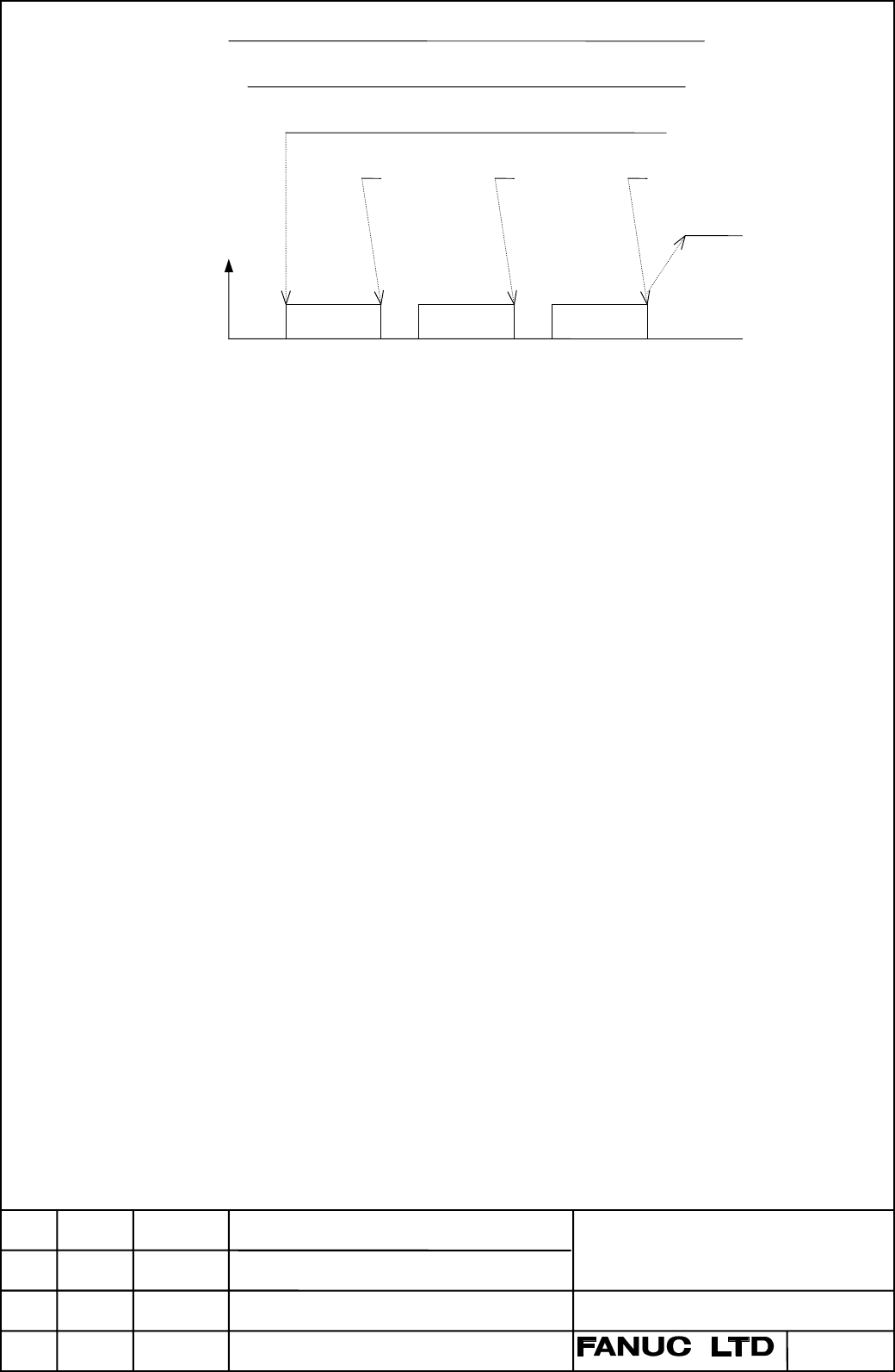
JOG
ZRN
+J1
Reference mark
ZRF1
Feedrate
FL rate
FL rate FL rate
Fig.2 Timing chart for reference position establishment
2.2 This function for simple synchronous axis
09
13
09
09
09
09
09
09
09
09
09
09
The function is available for only FS16i/18i-MA/MB
When the function is applied for simple synchronous axis, the following condition
should be kept.
(1) Distance coded linear scale with the same reference marks at intervals should
be applied for the master axis and the slave axis.
(2) The master axis scale and the slave axis scale should be installed in parallel
direction. (The zero positions should be faced the same direction.)
(3) To the parameters, which relates to this function (except No.1883, No.1884),
the same value must be set for the master axis and for the slave axis.
(4) During operating the establishment of reference position, the state of
synchronous control selection signal (SYNCJn<G0140>) should be kept.
Procedure for Reference Position Establishment by synchronous axis is as follows.
09
09
09
09
09
09
09
09
- When either reference mark of the master axis or the slave axis is detected, the
both axes stop. And the both axes are fed again at a Reference Position Return
FL Feedrate.
- The above mentioned operations are repeated until the master axis and the slave
axis detect enough (3 or 4) reference marks.
- Absolute position of both axes are calculated and Reference Position
Establishment Signal (ZRF1,ZRF2,...) turns to "1".
3/15
A- 61209EN
DRAW.No.
FANUC Series 16/18-MB/TB/MC/TC
FANUC Series 16i/18i/21i-MA/TA/MB/TB
Specifications of Distance Coded
Linear Scale Interface
Title
Descriptions of products are altered.
Straightness compensation is supported.
First edition
DESCRIPTION
A.Fukumoto
A.Fukumoto
DESIGNE
02.09.24
00.06.20
95.11.14
DATE
13
12
01
EDIT.
T.Endo
H.Kochiya
Contents Summary of FS 16/18-MB/TB/MC/TC Additional Manual
- Page 1FANUC Series 16/18-MB/TB/MC/TC FANUC Series 16i/18i/21i-MA/TA/MB/TB Distance Coded Linear Scale Interface Specifications CONTENTS 1. Outline .............................................. 2 2. Specifications ................................... 2 3. Parameter .........................................
- Page 21. Outline The interval of each reference marks of distance coded linear scale are variable. Accordingly, if the interval is determined, the absolute position can be determined. The CNC measures the interval of reference marks by axis moving of short distance and determines the absolute position. Co
- Page 3JOG ZRN +J1 Reference mark ZRF1 Feedrate FL rate FL rate FL rate Fig.2 Timing chart for reference position establishment 2.2 This function for simple synchronous axis 09 The function is available for only FS16i/18i-MA/MB 13 When the function is applied for simple synchronous axis, the following cond
- Page 4(Example of 3 points measurement system) Scale end Reference mark Master axis (1) (2) (3) Start point End Point Slave axis (a) (b) (c) In the above example, the following sequence is executed. 09 a. When the reference mark (1) of the master axis is detected, both master axis 09 and slave axis stop.
- Page 52.4 Note (1) In the following cases, the reference position establishment described in "2.1 09 Procedure for Reference Position Establishment" is not executed and the axis 09 moves to reference position. 09 (a) The reference position is already established and REF mode is selected and 09 feed axis d
- Page 6(4) In the following cases, this function does not perform. (a) Parameter No.1821(mark1 interval) or No.1882(mark2 interval) is "0". (b) The setting value of parameter No.1821 and No.1882 are the same. (c) Parameter No.1821 value ≥ No.1882 value*2 or No.1882 value ≥ No.1821 value*2 (5) Distance code
- Page 7(6) A difference of parameter No.1821 and No.1882 must be more than 4. 08 Example) 08 When the scale, which is that mark1 interval is 20.000mm and mark2 interval is 08 20.004mm, is used on IS-B machine : 08 When the detection unit of 0.001mm is selected, parameter No.1821 and No.1882 08 must be set
- Page 8(9) Straightness compensation function 12 When the reference point establishment of moving axis is executed after the 12 establishment of compensation axis, the compensation axis is moved by 12 straightness compensation amount when the reference point of moving axis is 12 established. 12 * The simul
- Page 93. Parameters #7 #6 #5 #4 #3 #2 #1 #0 1815 DCRx DCLx OPTx Data type : Bit axis type OPTx Position detector 0 : A separate pulse coder is not used. 1 : A separate pulse coder is used. (When a distance coded linear scale use, set "1".) DCLx Separate pulse coder 0 : A distance coded linear scale is not
- Page 10#7 #6 #5 #4 #3 #2 #1 #0 1818 RF2x RFSx Data type : Bit axis type RFSx When the conditions are as follows, the axis moves until the 09 reference position is established and : 09 0 : the axis moves to the reference point. 09 1 : sequence complete without moving to the reference point. 09 (Conditions)
- Page 111821 Reference counter size for each axis Data type : Two-word axis Unit of data : Detection unit Valid data range : 0 to 99999999 Set the interval of reference mark 1 of distance coded linear scale. 1882 Interval of reference mark 2 Data type : Two-word axis Unit of data : Detection unit Valid data
- Page 121883 Distance between scale zero and reference position (1) Data type : Two-word axis Unit of data : Detection unit Valid data range : -99999999 to 99999999 06 1884 Distance between scale zero and reference position (2) Data type : word axis 06 Unit of data : Detection unit*100,000,000 06 Valid data
- Page 13[ Example of parameter setting ] When IS-B and millimeter machine and using a scale figured below : Scale zero Plus direction Reference point Minus direction A B Mark1=Mark2 Mark1 Mark2 Mark1 Mark1 Mark2 Mark1 Mark2 Mark1 Mark2 Mark1 20.000 19.980 9.940 10.060 9.960 10.040 9.980 10.020 5.000 20.000m
- Page 14#7 #6 #5 #4 #3 #2 #1 #0 1817 SCPx 11 Data type : Bit axis type 11 SCP The direction of scale zero. 11 0: Minus side (reference point is located on the plus side based on the 11 scale zero) 11 1: Plus side (reference point is located on the minus side based on the 11 scale zero) 11 This parameter is
- Page 154. Alarm Number Message Contents 090 REFERENCE RETURN INCOMPLETE In case of distance coded linear scale I/F, the actual interval of reference marks is different from parameter (No.1821,1882) setting value. 5220 REFERENCE POINT ADJUSTMENT In case of distance coded linear scale I/F, 06 MODE the refere