Panel i, Maintenance Manual Additional Manual Page 17
Additional Manual
EDIT.
SHEET
DRAW. NO.
CUST.
TITLE
17
/
30
DESCRIPTION DESIG. DATE
FANUC PANEL i
Maintenance Manual
A
-83138E
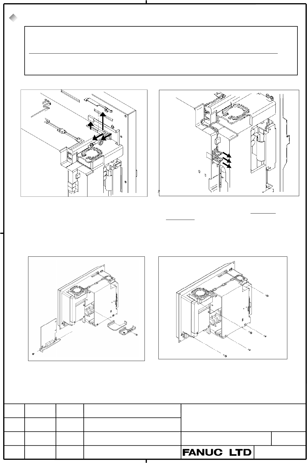
5.2. Method of Removing Case Cover
(1)Pull out LCD Connector (In case of 15.0” LCD) (2) Pull out FAN/Battery Cable Connectors
(3) Remove PCI cards (4) Remove screws for cover.
1
2
1. Screw off at right upper corner.
2. Remove a cable clamp.
3. Remove a plate holding connector.
4. Pull out LCD cable connector.
Pull out two FAN connectors. FAN
connector has a latch with tab. So press it by
screwdriver etc.
Pull out battery connector.
1. Screw off at right upper corner in case o
f
10.4” or 12.0” LCD.
2. Screw off other four screws.
1
2
1
2
3 4
1. Remove PCI holding parts.
2. Screw PCI cards off.
If this operating takes more than 5 minutes, BIOS settings may be erased because battery cable is pulled out.
In that case “251: System CMOS checksum bad – Default configuration used.” & “Press <F2> to enter SETUP”
are displayed after next turning on.
Therefore in case of usage with changing BIOS settings, confirm changed items before this operating.
If the
messages are displayed, change BIOS settings as before.
In case of usage without changing BIOS setting (setting on manufacture), exit BIOS setting if the message is
displayed.
Contents Summary of Panel i, Maintenance Manual Additional Manual
- Page 1FANUC PANEL i Maintenance Manual INTRODUCTION This manual describes maintenance information of the FANUC PANEL i with Celeron 733MHz / Pentium III 866MHz / Pentium III 1.26GHz. ATTENTION - The copyright of Windows R 2000, Windows R XP and other software provided with PANEL i is owned by Microsoft Co
- Page 2FANUC PANEL i Maintenance Manual INDEX Page 1. System Block Diagram 3 2. List of the PCBs, Units, Maintenance Supplies and Tools 5 2.1. List of PCBs 5 2.2 List of Maintenance Units 6 2.3. List of CPU and Memory 8 2.4. List of Maintenance Parts 8 2.5. List of Maintenance Tools 8 3. Configuration of t
- Page 31. System Block Diagram USB Keyboard and Controller CP1 In case of Touch Panel Touch Panel Controller PCB CN4 CD37 PCMCIA I/F PCMCIA Clock CA82 Controller Generator JA63 CRT USB I/F FDD SIGNAL CD46L CPU CD34 Memory CD32L KEYBOARD LCD DIMM CNA1 Signal Chipset CA85 LVDS DV (GMCH) CD32U MOUSE CA79 LVDS
- Page 4*1 : Detail of Inverter In case of 10.4” Main Board Inverter (A20B-8100-093X) 10.4”LCD Unit CN2 CN1 CPC11 In case of 12.1”LCD 12.1”LCD Inverter Unit CP1 CP2 CP31 In case of 15.0”LCD 15.0”LCD Inverter Unit CN02 CN01 CN03 CN04 CN05 TITLE FANUC PANEL i Maintenance Manual DRAW. NO. CUST. A-83138E SHEET
- Page 52. List of the PCBs, Units, Maintenance Supplies and Tools 2.1. List of PCBs (1) Main PCB. CNC Unit LCD type Specification of Applied Basic Unit Main PCB 160 i 10.4”/12.1” A20B-8100-0930 A08B-0084-B001~4, -B011~4 /180 i PANEL i A13B-0196-B001~4, -B011~4 /210 i 15.0” A20B-8100-0931 A08B-0084-B021, -B
- Page 6(4) Touchpanel PCB CNC Unit Specification of Applied Basic Unit Touchpanel PCB 160 i PANEL I A20B-8001-0620 A08B-0084-B003~4 A13B-0196-B003~4 /180 i A08B-0084-B013~4 A13B-0196-B013~4 /210 i A08B-0084-B023 A13B-0196-B023 PANEL i A20B-8002-0310 A08B-0084-B401, -B403 A13B-0196-B401, -B403 for Automotiv
- Page 7(2) Base Unit Unit CNC LCD I/O Link Softk Touch Specification of Applied Unit type Adapter ey panel Base Unit *3 PANEL i 160 i 10.4” None X X A08B-0084-D001 A08B-0084-B001 A13B-0196-B001 /180 i LCD O X A08B-0084-D002 A08B-0084-B002 A13B-0196-B002 /210 i X O A08B-0084-D003 A08B-0084-B003 A13B-0196-B0
- Page 82.3. List of CPU and Memory Name Specification of Applied Order Maintenance Parts Specification CPU Celeron733MHz A08B-0084-C210 A08B-0084-H010 PentiumIII 866MHz A08B-0084-C220 A08B-0084-H020 PentiumIII 1260MHz A08B-0084-C230 A08B-0084-H030 Memory 128MB A76L-0500-0020 A08B-0084-H001 256MB A76L-0500-
- Page 93. Configuration of the PCB 3.1. Parts Layout CA85 VR1 CPU CA79 Socket G/A PCMCIA (GMCH) Controller DIMM Socket (SD-RAM) JA64 CA82 CK22 CPD12 CK23 BIOS Chipset2 Chipset3 (ICH2) SIO CD46L ROM CD37 CPC11 CD41M CD41L JD33 JD46 JD9 JA61 JA63 CD34 CD32U (MS) CK21 CA81A CD38U CD32L CA86 CK20 (KB) CA81B TM
- Page 10CA78B PCI Slot 2 LED2A LED1A CA78A PCI Slot 1 Peripheral HSSB COP7 Controller Controller JA64 PC Extension I/F Backplane for 160i/180i/210i ( A20B-8002-0250) Parts Layout CA78B PCI Slot 2 LED2A LED1A CA78A PCI Slot 1 HSSB PCI I/F COP21M Controller JA64 PC Extension I/F Backplane for 300i (A20B-8002-
- Page 113.2. Adjustment (1) Setting of Short Plug Name Meaning Settings Remark TM1 FDD Mode Short Setting for designated FDD. TM1 Default on manufacture. Open Setting for old FANUC FDD. TM1 TM2(TM18) Reserved PWB revision is 03 or less. Default on manufacture. TM3 TM2 Never change. TM4 TM3 : Open (TM4 will
- Page 123.3. LED Display (1) LED on Main Board GR5 RE2 GR4 RE3 GR6 RE1 CD41M CD32 GR3 GR2 GR1 Name1 Name2 Color Status RE1 TRM Red Thermal Alarm. Thermal is not in regulated range. RE2 BAT Red Battery alarm. The battery on PANEL i is exhausted. Please exchange it. RE3 FAN Red FANs for basic unit or FAN for
- Page 134. BIOS Setup 4.1. What is ‘BIOS SET-UP’ “BIOS Set-up” is a program to set up BIOS settings, and operating environment for the PANEL i is defined by these BIOS settings. It is unnecessary to run the set-up program normally because default BIOS settings are set at shipping. Use PANEL i with this defa
- Page 144.3. How to Begin the ‘BIOS SET-UP’ 1. Finish working and store the data. 2. Turn off and connect a full-keyboard, and turn on again. 3. BIOS set-up will run with pressing “F2” key while “Press
to enter SETUP.” is displayed. 4. Menu screen is displayed. Change parameters if it is necessary. Pho - Page 154.5. BIOS Diagnostic Message After turning on the system POST (Power On Self Test) is executed. Diagnosis messages in the following table may be displayed. Marks in item “To be solved” represent as bellow. O : Something of hardware may be failure. Solve these troubles. 1 : When battery supply is sto
- Page 165. Maintenance Supplies 5.1. Method of Exchanging a Battery The time from disconnecting the cable of old battery to connecting the cable of new battery should be shorter than 5 minutes. BIOS settings will be not erased when bellow procedures are done correctly. But if following massage are displayed
- Page 175.2. Method of Removing Case Cover If this operating takes more than 5 minutes, BIOS settings may be erased because battery cable is pulled out. In that case “251: System CMOS checksum bad – Default configuration used.” & “Press
to enter SETUP” are displayed after next turning on. Therefore in - Page 18(5) Confirm a Type of PCI Holding plate (6) Remove PCI Holding Plate -1- (In only case of old type) 1. Old Type 2. New Type 1. In case of old type remove it at (6). Screw off two screws. 2. In case of new type loosen marked screw. Then remove case cover at (8). (7) Remove PCI Holding Plate -2- (In o
- Page 195.3 Method of Attaching Case Cover (1)Attach Case Cover after Adjusting Upper Side This point is tight in case of 300i. Never push DIMM latch. Set PCB of Backplane and power PCB to holding parts. (2) Set PCI Holding Plate, Then Screw Case Cover On with 4 or 5 screws. (3) Insert PCI Cards, then Hold
- Page 205.4. Method of Exchanging Fuse Investigate the cause that fuse is blown out at first, then remove it. Fuse is blown out when power lines are shorted in PANEL i. If the fuse is blown out, check bellow points. - Any conductor is shorted to the main board. - Failure of PCI extended card or error at ins
- Page 215.5. Method of Exchanging FAN 5.5.1. Method of Exchange FAN of the Basic Unit (1) Make sure that PANEL i is turned off. (2) Prepare a new FAN . (3) Pull out the connector of fan power. This connector has a latch, therefore release the latch and pull out it as below figure. (4) Exchange a fan. Attent
- Page 225.3.2. Method of Exchanging FAN for the HDD unit (1) Make sure that PANEL i is turned off. (2) Prepare a new fan. (3) Disconnect the fan connector from CPE11C. The connector has a latch, therefore disconnect it while raising upward it a little. (4) Screw the old fan off. (5) Screw a new fan on, and
- Page 235.6. Method of Exchanging CPU Unit (1) Make sure that PANEL i is turned off. (2) Remove case cover (Refer to 5.2). (3) Screw off 2 screws, then remove holding plate of the CPU(A). (4) Pull up the CPU socket lever, then remove CPU unit (B). (5) Set new CPU unit. Mount parts in a reverse order. B A Ho
- Page 245.7. Method of Exchanging LCD Backlight Note) It is not possible to exchange a backlight of 15.0”LCD. Exchanging of Base Unit for maintenance (A08B-0084-Dxxx) is available in case of 15.0”LCD. 5.7.1 Exchanging 10.4”LCD Backlight (1) Make sure that PANEL i is turned off. (2) Remove case cover (Refer
- Page 25(6) Remove Plastic panel and 4 screws. 4 Screws Figure: Exchanging LCD Backlight at 10.4”LCD -3- (7) Remove LCD unit and 4 screws. 4 Screws Figure: Exchanging LCD Backlight at 10.4”LCD -4- TITLE FANUC PANEL i Maintenance Manual DRAW. NO. CUST. A-83138E SHEET EDIT. DATE DESIG. DESCRIPTION 25/30
- Page 26(8) Unlock like the below figure, pull out the case with the backlight, and exchange. Locked here CP1 Pull up this softly and pull out the backlight (detail is below figure) Rear of LCD Lock Pull up here Do not pull the cable when pull out the backlight. TITLE FANUC PANEL i Maintenance Manual DRAW.
- Page 275.7.2 Exchanging 12.1”LCD Backlight (1)-(7) Remove LCD unit in the same way as 5.7.1(1)-(7). Note that LCD backlight cable is two in case of 12.1” LCD. (8) In case of 12.1”LCD type, screw off at 2 points. And slide and pull out the LCD Backlights as below figure, and exchange them. Connector 2. Pull
- Page 285.8. Method of Exchanging Touch Panel Protection Sheet PANEL i has a Touch Panel Protection Sheet on the face of Touch Panel to protect the Touch Panel. When the screen cannot be watched clearly because of some damages or stains, exchange the Touch Panel Protection Sheet. Please prepare the followin
- Page 29Method of exchanging Touch Panel Protection Sheet (A02B-0236-K130) 1. At first, strip the old Touch Panel Protection Sheet off. Tab for exchange 2. Clean the face of the LCD well. 3. Strip the film on the back of the new Touch Panel Protection Sheet (this side is to stick on the LCD face.) 4. Put th
- Page 306. Trouble Shooting Status Measure 1 Power supply is good, but - LED all off? Power is not supplied, or fuse may be blown out. Yes nothing displayed. No After new device or cable is installed? Remove it and Yes check again. No After case cover attached? DIMM latch may be unlocked. Yes Check DIMM is