FANUC Series 16i/18i/21i Additional Manual Page 4
Additional Manual
2002/08/09 T.Inagaki E.Genma
2. Specifications (Linear scale I/F with absolute address
referenced mark (A/B phase))
2.1 Procedure for Reference Position Establishment
(1) Select the JOG mode, and set the manual reference position return selection signal
ZRN to "1".
(2) Set a direction selection signal(+J1,-J1,+J2,-J2,…) for a target axis.
(3) The axis is fed at a constant low speed (reference position return FL feedrate specified
by parameter (No.1425) setting).
(4) When a reference mark is detected, the axis stops, then the axis is fed at a constant low
speed again.
(5) Above (4) is executed repeatedly until two or three or four reference marks are
detected. And absolute position is determined and reference position establishment
signal (ZRF1,ZRF2,ZRF3,+ _…) turns to "1". The number of reference marks to be
detected is defined by parameter No.1802.
The axis does not stop and reference position establishment is proceeded even if the feed
axis direction selection signal (+J1,-J1,+J2,-J2,…) turns to "0" between step (2) and (5).
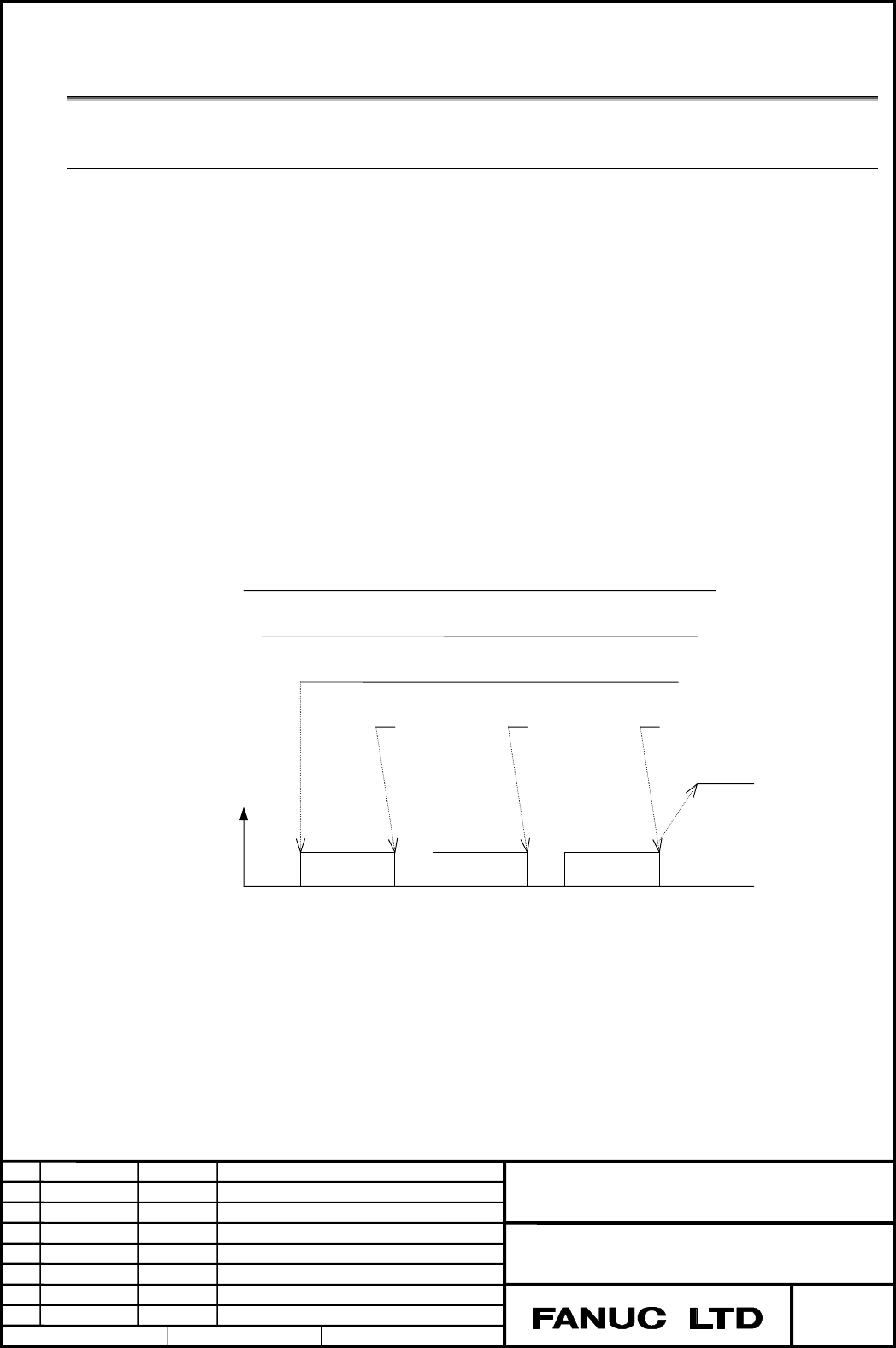
The timing chart for this procedures is given below.
Title
JOG
ZRN
+J1
Reference mark
ZRF1
Feedrate
FL rate FL rate
FL rate
Fig.2 Timing chart for reference position establishment
A-78754EN
FANUC Series 16i/18i/21i –B, 0i –B/C
Linear scale I/F with absolute address referenced
mark / Distance coded scale
Drawing No.
Page
Descri
p
tionDate Edit
4/32
03 2004/11/30 T,Inagaki (3) is added or altered.
02 2002/11/18 T
,
Ina
g
aki
(
2
)
is added or altered. E.Genma
Contents Summary of FANUC Series 16i/18i/21i Additional Manual
- Page 1FANUC Series 16i/18i/21i-B, 0i-B/C Linear scale I/F with absolute address referenced mark (A/B phase) / Linear scale with distance-coded reference marks (serial) Specifications 1. Outline ................................................................................................................
- Page 21. Outline By using optional function "Linear scale I/F with absolute address referenced mark", we can use "Linear scale I/F with absolute address referenced mark (A/B phase)", and "Linear scale with distance-coded reference marks (serial)" 1.1 Linear scale I/F with absolute address referenced mark
- Page 31.2 Linear scale with distance-coded reference marks (serial) The basic structure of Linear scale with distance-coded reference marks (serial) is same as A/B-phase scale (Linear scale with absolute address referenced mark). But this scale differs from A/B-phase in point of circuit. High-resolution s
- Page 42. Specifications (Linear scale I/F with absolute address referenced mark (A/B phase)) 2.1 Procedure for Reference Position Establishment (1) Select the JOG mode, and set the manual reference position return selection signal ZRN to "1". (2) Set a direction selection signal(+J1,-J1,+J2,-J2,…) for a t
- Page 52.2 Simple synchronous axis The function is available for only FS16i/18i/21i-MB,18i-MB5. When the function is applied for simple synchronous axis, the following condition should be kept. (1) Linear scale I/F with absolute address referenced mark (A/B phase) with the same reference marks at intervals
- Page 6【Synchronization compensation function】 (2) By setting parameter 8301#7(in case that only one master/slave axis pair is in sync) or 8303#7(in case that more than one master/slave axis pair is in sync) is set to '1', compensation pulses are outputted to the slave axis to adjust its position such that
- Page 72.4 Note (1) In the following case, P/S090 alarm occurs. (a) The actual interval of reference marks is different from parameter setting value. (2) In this procedure, the axis does not stop until three or four reference marks are detected. If this procedure is started at the position near the scale e
- Page 8(5) Rotary encoder with absolute address referenced mark (A/B phase) (a) When the rotary encoder with absolute address referenced mark (A/B phase) is used, please set a parameter No.1815#3 (DCR) to “1”. In case of rotary encoder with absolute address referenced mark (A/B phase), the marker interval
- Page 9(6) A difference of parameter No.1821 and No.1882 must be more than 4. Example) When the scale, which is that mark1 interval is 20.000mm and mark2 interval is 20.004mm, is used on IS-B machine : When the detection unit of 0.001mm is selected, parameter No.1821 and No.1882 must be set "20000" and "20
- Page 10(8) Measurement of two point (parameter No.1802#2(DC2)=1) (a) Please set the direction of the scale zero point in the parameter (No.1817#4 (SCP)) correctly at two point measurement. Because an incorrect coordinate system will be established when a wrong value is set in parameter SCP. It is very dang
- Page 113. Specifications (Linear scale with distance-coded reference marks (serial)) 3.1 Procedure for Reference Position Establishment (1) Select the JOG mode, and set the manual reference position return selection signal ZRN to "1". (2) Set a direction selection signal(+J1,-J1,+J2,-J2,…) for a target axi
- Page 123.2 Simple synchronous axis The function is available for only FS16i/18i/21i-MB,18i-MB5. When the function is applied for simple synchronous axis, the following condition should be kept. (1) Linear scale with distance-coded reference marks (serial) with the same reference marks at intervals should b
- Page 133.3 Reference Position Return (1) When the reference position is not established and the axis moved by turning the feed axis direction signal (+J1,-J1,+J2,-J2,...) to “1” in REF mode, the reference position establishment procedure is executed. (2) When the reference position is already established a
- Page 143.4 Note (1) When the Linear scale with distance-coded reference marks (serial) is used, please don't forget to set parameter No.1818#3(NSD) to 1. And distance coded rotary encoder (3) (serial type) is unavailable. (2) On the Linear scale with distance-coded reference marks (serial), the axis does n
- Page 15(5) Straightness compensation function When the reference point establishment of moving axis is executed after the establishment of compensation axis, the compensation axis is moved by straightness compensation amount when the reference point of moving axis is established. (6) The linear scale with
- Page 16(7) Rotary encoder with distance-coded reference marks (serial output circuit C) (3) (a) When the rotary encoder with distance-coded reference marks (serial) is used, the parameter setting is as same as the normal linear type of distance-coded reference marks (serial). In case of rotary encoder with
- Page 17[The setting of reference position on rotation axis B-type with movable range under a (3) rotation] In the case of a rotary axis whose movable range is under one rotation, it is possible to know its position under one rotation, even if a rotary scale without rotary data (the number of rotation) is u
- Page 184. Parameter #7 #6 #5 #4 #3 #2 #1 #0 1815 DCRx DCLx OPTx [Data type] Bit axis OPTx Position detector 0: A separate pulse coder is not used. 1: A separate pulse coder is used. DCLx As a separate position detector, the linear scale with reference absolute addressing mark (A/B phase) / the Linear scale
- Page 19#7 #6 #5 #4 #3 #2 #1 #0 1802 DC2 DC4 [Data type] Bit DC4 When the reference position is established on the linear scale with reference marks: 0: An absolute position is established by detecting three reference marks. 1: An absolute position is established by detecting four reference marks. Caution T
- Page 20#7 #6 #5 #4 #3 #2 #1 #0 1818 SDCx RF2x RFSx [Data type] Bit axis RFSx If an automatic reference position return (G28) is made before the reference position is established, the reference position is established first then, 0: A movement to reference position is made. 1: A movement to reference positi
- Page 211821 Reference counter size for each axis [Data type] 2-word axis [Unit of data] Detection unit [Data range] 0 to 99999999 Sets the intervals of mark 1 of the linear scale with abssolute addressing referenced marks. Caution On the linear scale with distance-coded reference marks (A/B phase), this pa
- Page 221867 threshold value converting scale data (all axes) (3) [Data type] 2-word [Unit of data] Increment system IS-A IS-B IS-C Unit Rotation axis 0.01 0.001 0.0001 deg [Data range] 0 to 99999999 In the case that scale data is larger than this parameter value, it is converted to be continuous data in mo
- Page 23[The method to investigate the discontinuous point of scale data] (3) Before using this function, it is necessary to know a discontinuous point in following process. But before executing following operation, parameter No.1818#2 should be set to ‘0’. (Reference position return by JOG feed or rapid tr
- Page 24By this process it is possible to know approximate position of a discontinuous (3) point. In the case of the figure (page17) 1. A reference position return finishing 2. Move to machine coordinate value –45.000 3. Turn CNC off and on. Move to machine coordinate value 45.000 (the other side) and move
- Page 251883 Distance from the zero point of the linear scale with absolute addressing reference marks (A/B phase) to the reference position / (3) Distance from the standard point of the linear scale I/F with absolute address referenced mark (serial) to the reference position [Data type] 2-word axis [Unit o
- Page 26[ In case of linear scale with absolute addressing reference mark (A/B phase)] (3) The scale zero means a point where reference mark 1 and reference mark 2 are equal. Generally, this is a virtual point that exists on the out of scale stroke.( Refer to following figure ) When a reference point is loc
- Page 27[ Example of parameter setting ] (Linear scale with absolute addressing reference mark (A/B (3) phase)) When IS-B and millimeter machine and using a scale figured below : Scale zero Plus direction Reference point Minus direction A B Mark1=Mark Mark1 Mark2 Mark1 Mark1 Mark2 Mark1 Mark2 Mark1 Mark2 Ma
- Page 28[The setting method of parameter No.1883] (Linear scale with absolute addressing reference mark (A/B phase)) When the measurement of a parameter No.1883 (Distance between scale zero and reference position) is difficult, you can determine the setting value by the following procedure. (1)Set "1" to pa
- Page 29[The setting method of parameter No.1883] (Linear scale with distance-coded reference marks (serial)) You can determine the setting value by the following procedure. (1)Set "1" to parameter No.1815#2 to make this function available. Set "0" to parameter No.1240. Set "0" to parameter No.1883,1884. (2
- Page 30#7 #6 #5 #4 #3 #2 #1 #0 1817 SCPx [Data type] Bit axis SCPx If DC2x (Paramete No.1802#2) is set to '1', the scale-zero point of the linear scale with absolute addressing referenced mark is: 0: On the negative direction side. (Viewed from the scale zero point, the reference position is on the positiv
- Page 31#7 #6 #5 #4 #3 #2 #1 #0 (2) 8301 SOF [Data type] Bit SOF The synchronization function of simple synchronous control (one pair) is 0: Not used. 1: Used. #7 #6 #5 #4 #3 #2 #1 #0 8303 SOFx [Data type] Bit axis SOF The synchronization function of simple synchronous control (plural pair) is 0: Not used.
- Page 325. Alarm Number Message Contents 090 REFERENCE RETURN INCOMPLETE In case of Linear scale I/F with absolute address referenced mark (A/B phase), the actual interval of reference marks is different from parameter (No.1821,1882) setting value. 5220 REFERENCE POINT ADJUSTMENT In case of Linear scale I/F