Laser C-Series Operators manual Page 79
Operators manual
Contents Summary of Laser C-Series Operators manual
- Page 1GE Fanuc Automation Europe Computer Numerical Controls Laser C Series Operator‘s Manual B-70114EN/04 TECHNOLOGY AND MORE
- Page 2
- Page 3B–70114EN/04 PREFACE PREFACE This document describes the following models. Model Abbreviation FANUC LASER–MODEL C1500B C1500B FANUC LASER–MODEL C2000B C2000B FANUC LASER–MODEL C2000C C2000C FANUC LASER–MODEL C3000C C3000C FANUC LASER–MODEL C3000D C3000D FANUC LASER–MODEL C4000A C4000A FANUC LASER–MO
- Page 4PREFACE B–70114EN/04 And, these models conform with EMC Directive 89/336/EEC. 401-0597 Japan 401-0597 Japan p–2
- Page 5B–70114EN/04 PREFACE 401-0597 Japan 401-0597 Japan p–3
- Page 6PREFACE B–70114EN/04 401-0597 Japan 401-0597 Japan p–4
- Page 7B–70114EN/04 PREFACE p–5
- Page 8PREFACE B–70114EN/04 p–6
- Page 9B–70114EN/04 Table of Contents PREFACE . . . . . . . . . . . . . . . . . . . . . . . . . . . . . . . . . . . . . . . . . . . . . . . . . . . . . . . . . . . . . . . . . . . p–1 1. OVERVIEW . . . . . . . . . . . . . . . . . . . . . . . . . . . . . . . . . . . . . . . . . . . . . . . . . . . . . . . .
- Page 10TABLE OF CONTENTS B–70114EN/04 3.8 LASER BEAM . . . . . . . . . . . . . . . . . . . . . . . . . . . . . . . . . . . . . . . . . . . . . . . . . . . . . . . . . . . . . . . . . . . 76 3.8.1 Position and Tolerance of Laser Beam Exit . . . . . . . . . . . . . . . . . . . . . . . . . . . . . . . . . . .
- Page 11B–70114EN/04 1. OVERVIEW 1 OVERVIEW In this manual, we have tried as for as possible to address all issues. However, space restrictions prevent us from describing everything that must not be done, or which cannot be done, because there are so many possibilities. Therefore, all matters which are not
- Page 121. OVERVIEW B–70114EN/04 1.1 This manual consists of the following chapters and appendixes: MANUAL CONTENTS 1. OVERVIEW Chapter 1 covers the configuration of the manual, applicable models, related manuals, and provides notes on reading the manual. 2. SAFETY Chapter 2 covers the warnings and precauti
- Page 13B–70114EN/04 1. OVERVIEW 1.2 This manual covers the following models: APPLICABLE Model Abbreviation MODELS FANUC LASER–MODEL C1500B C1500B FANUC LASER–MODEL C2000B C2000B FANUC LASER–MODEL C2000C C2000C FANUC LASER–MODEL C3000C C3000C FANUC LASER–MODEL C3000D C3000D FANUC LASER–MODEL C4000A C4000A F
- Page 141. OVERVIEW B–70114EN/04 1.4 This manual contains precautions which must be observed during operation of the laser oscillator, to ensure the operator’s safety and prevent FOR SAFE damage to the oscillator. Each precaution is indicated by “Warning” or OPERATION “Caution” according to its severity. Su
- Page 15B–70114EN/04 2. SAFETY 2 SAFETY C1500B, C2000C (C2000B), C3000D (C3000C), C4000A, C6000B produce the rated laser output power of 1500W, 2000W, 3000W, 4000W, 6000W. The CO2 laser beam is the wavelength of 10.6 mm, far infrared, and is invisible to human eyes. The adequate care must be taken, therefor
- Page 162. SAFETY B–70114EN/04 2.1 1) Potential hazards Laser oscillator emits CO2 laser beam(10.6 mm), which is high power LASER BEAM and invisible. D Being directly exposed to the CO2 beam could severely burn you. D The CO2 beam could bource off your workpiece and burn your eyes or skin. FANUC LASER C ser
- Page 17B–70114EN/04 2. SAFETY Fig. 2.1 (f) is the position of panel that laser beam exposure is occurred without panel in C4000A, when your maintenance. Fig. 2.1 (g) is the position of panel that laser beam exposure is occurred without panel in C6000B, when your maintenance. Fig. 2.1 (a) The position of la
- Page 182. SAFETY B–70114EN/04 Fig. 2.1 (c) The position of laser beam delivery (C4000A) Fig. 2.1 (d) The position of laser beam delivery (C6000B) 8
- Page 19B–70114EN/04 2. SAFETY Fig. 2.1 (e) Laser beam exposure position without panel as operating (C1500B, C2000B, C2000C, C3000C, C3000D) Fig. 2.1 (f) Laser beam exposure position without panel as operating (C4000A) 9
- Page 202. SAFETY B–70114EN/04 Fig. 2.1 (g) Laser beam exposure position without panel as operating (C6000B) 10
- Page 21B–70114EN/04 2. SAFETY 2.2 1) Potential hazards There is RF voltage of 3 to 4kVo–p in the cabinet of the laser oscillator. HIGH VOLTAGE There is 200 VAC power in the relay panel, be careful not to touch the high voltage. 2) Safety recommendations When it checks the oscillator and exchange the unit,
- Page 222. SAFETY B–70114EN/04 Front side Back side Fig. 2.2 (a) The position of high voltage in C1500B (Front side, Back side) 12
- Page 23B–70114EN/04 2. SAFETY Front side Back side Fig. 2.2 (b) The position of high voltage in C2000B (Front side, Back side) 13
- Page 242. SAFETY B–70114EN/04 Front side Back side Fig. 2.2 (c) The position of high voltage in C2000C (Front side, Back side) 14
- Page 25B–70114EN/04 2. SAFETY Front side Back side Auxiliary unit Fig. 2.2 (d) The position of high voltage in C3000C (Front, Back, AUX) 15
- Page 262. SAFETY B–70114EN/04 Front side Back side Fig. 2.2 (e) The position of high voltage in C3000D (Front side, Back side) 16
- Page 27B–70114EN/04 2. SAFETY Front side Back side Fig. 2.2 (f) The position of high voltage in C4000A (Front side, Back side) 17
- Page 282. SAFETY B–70114EN/04 Front side Back side Fig. 2.2 (g) The position of high voltage in C6000B (Front side, Back side) 18
- Page 29B–70114EN/04 2. SAFETY 2.3 1) Potential hazards CO2 beam is delivery from oscillator. Direct or scattered beam is SAFETY exposed. ENCLOSURE (AT 2) Safety recommendations YOUR WORK Mount the safety enclosure made of acrylic resin which can absorb the STATION) laser beam around the working environment
- Page 302. SAFETY B–70114EN/04 2.6 1) Potential hazards When you touch a part of high temperature, your skin burn. HIGH TEMPERATURE 2) Safety recommendations The pipes of the gas circular system are very a high temperature. Do not touch pipes, heat exchanger and turbo blower because it does not do the burn.
- Page 31B–70114EN/04 2. SAFETY Front side Back side Fig. 2.6 (a) The position of high temperature in C1500B (Front side, Back side) 21
- Page 322. SAFETY B–70114EN/04 Front side Back side Fig. 2.6 (b) The position of high temperature in C2000B (Front side, Back side) 22
- Page 33B–70114EN/04 2. SAFETY Front side Back side Fig. 2.6 (c) The position of high temperature in C2000C (Front side, Back side) 23
- Page 342. SAFETY B–70114EN/04 Front side Back side Auxiliary unit Fig. 2.6 (d) The position of high temperature in C3000C (Front , Back, Aux) 24
- Page 35B–70114EN/04 2. SAFETY Front side Back side Fig. 2.6 (e) The position of high temperature in C3000D (Front side, Back side) 25
- Page 362. SAFETY B–70114EN/04 Front side Back side Fig. 2.6 (f) The position of high temperature in C4000A (Front side, Back side) 26
- Page 37B–70114EN/04 2. SAFETY Front side Back side Fig. 2.6 (g) The position of high temperature in C6000B (Front side, Back side) 27
- Page 382. SAFETY B–70114EN/04 2.7 Fig. 2.7 (a)–(g) show the location of the warning labels indicating the high voltage and laser beam path. WARNING LABELS Fig. 2.7 (a) is the location of the warning sticker at front side. (C1500B, C2000B, C2000C, C3000C, C3000D) Fig. 2.7 (b) is the location of the warning
- Page 39B–70114EN/04 2. SAFETY Fig. 2.7 (b) The location of warning sticker at back side (C1500B, C2000B, C2000C, C3000C, C3000D) Fig. 2.7 (c) The location of the warning sticker (Auxiliary unit of C3000C) 29
- Page 402. SAFETY B–70114EN/04 Fig. 2.7 (d) The location of warning sticker at front side. (C4000A) Fig. 2.7 (e) The location of warning sticker at back side. (C4000A) 30
- Page 41B–70114EN/04 2. SAFETY Fig. 2.7 (f) The location of warning sticker at front side. (C6000B) Fig. 2.7 (g) The location of the warning sticker at back side. (C6000B) 31
- Page 422. SAFETY B–70114EN/04 D Detail of warning sticker Warning logotype 7000W 32
- Page 43B–70114EN/04 2. SAFETY Warning logotype Label for defeasible non–interlocked protective housing Label for defeasible non–interlocked protective housing 33
- Page 442. SAFETY B–70114EN/04 Caution label for lifting Aperture label Label of non–interlocked protective panel 34
- Page 45B–70114EN/04 2. SAFETY Identification label 80 110 110 150 150 190 300 Address label High voltage warning label 35
- Page 462. SAFETY B–70114EN/04 Supply voltage label Label of over–current protective 36
- Page 47B–70114EN/04 2. SAFETY Label of motor and transformer (C1500B,C2000B,C2000C) Label of motor and transformer (C3000C) 37
- Page 482. SAFETY B–70114EN/04 Label of motor and transformer (C3000D) Label of motor and transformer (C4000A) 38
- Page 49B–70114EN/04 2. SAFETY Label of motor and transformer (C6000B) Label of warning light Maintenance label 39
- Page 502. SAFETY B–70114EN/04 Certification label Short–circuit interrupting capacity of main breaker Caution label for lifting 40
- Page 51B–70114EN/04 2. SAFETY 2.8 All the laser products have to comply with the various kinds of laser safety regulations, which include the use of key control. For instance, FDA KEY CONTROL PART 1040 PERFORMANCE STANDARDS FOR LIGHT–EMITTING PRODUCTS, Sec 1040. 10 (f), (4) states: “Each laser system class
- Page 522. SAFETY B–70114EN/04 2.10 Press the emergency stop button when it is dangerous and breaks down. The oscillator is stopped discharging, gas pressure control and stand by EMERGENCY STOP purge state. BUTTON Use the one with the compulsion dissociation mechanism for the relay used for the emergency st
- Page 53B–70114EN/04 2. SAFETY 2.12 Inapposite use and the result are described in each explanation place. Inapposite major use are described in the following. INAPPOSITE USE OF LASER OSCILLATOR (1) The gas with different composition and purity from the specification is connected with the oscillator. The os
- Page 543. INSTALLATION B–70114EN/04 3 INSTALLATION 44
- Page 55B–70114EN/04 3. INSTALLATION 3.1 CONDITION 3.1.1 (1) Ambient temperature Environmental +5 to 30°C Conditions (2) Temperature drift Max 1.1°C/min (3) Humidity <75% (relative) (4) Vibration Acceleration <0.05G Amplitude <5µm (5) Atmosphere Free from dust and volatile vapor 3.1.2 (1) Input power and ma
- Page 563. INSTALLATION B–70114EN/04 3.1.4 (1) Cooling water specification Cooling Water The quality of cooling water is specified in the table below. If tap water is used, it should be treated in an ion exchanger. Refrigerator/air–conditioner cooling water quality standard (JRA–9001–1980) pH (25°C) 6.0 to
- Page 57B–70114EN/04 3. INSTALLATION Caution In winter or in a cold district, when the oscillator is at a rest and the ambient temperature gets to or below the freezing point, the cooling water in the oscillator freezes, possibly breaking the water pipe or damaging the chilling unit. When the oscillator is
- Page 583. INSTALLATION B–70114EN/04 3.2 TRANSPORTATION 3.2.1 In lifting the FANUC LASER C series, be sure to use the four eyebolts Lifting Laser Oscillator screwed into the top surface of the cabinet as shown in the figure. Never lift using only the two bolts. The weight is shown following tables. The perm
- Page 59B–70114EN/04 3. INSTALLATION 3.2.2 1) Clamp Packing When shipped from FANUC, the two components of the laser listed below are in the clamped position. Because this is for shipment only, remove the clamp during the installation. Be sure to use the clamp, when the machine is shipped again. (1) Optical
- Page 603. INSTALLATION B–70114EN/04 Fig. 3.2.2 (b) Clamp layout (C4000A) 50
- Page 61B–70114EN/04 3. INSTALLATION Fig. 3.2.2 (c) Clamp layout (C6000B) 51
- Page 623. INSTALLATION B–70114EN/04 Fig. 3.2.2 (d) Clamp layout (C6000B) CAUTION If the machine is not clamped during transportation, the optical resonator may cause distortion or may be damaged. 52
- Page 63B–70114EN/04 3. INSTALLATION 2) Water Be sure to drain water in the oscillator at shipment. Refer to the maintenance manual for draining. CAUTION If water remains in the oscillator, internal water pipes may be damaged in cold climates. 3.2.3 (1) Temperature –20 to 50°C Environmental Condition CAUTIO
- Page 643. INSTALLATION B–70114EN/04 3.4 In FANUC LASER C series, the two type of that is the four taps and hole are prepared in the base as shown in the figure for fixing the laser cabinet BASE OF against the machine base. OSCILLATOR Fig. 3.4 (a) Mounting (A) Fig. 3.4 (b) Mounting (B) 54
- Page 65B–70114EN/04 3. INSTALLATION Fig. 3.4 (c) Cabinet base (C1500B, C2000B, C2000C, C3000C, C3000D, C4000A) Fig. 3.4 (d) Cabinet base (C6000B) 55
- Page 663. INSTALLATION B–70114EN/04 3.5 The maintenance areas of FANUC LASER C series are shown in the figures below. The customer is requested to prepare adequate space MAINTENANCE AREA around the laser even for the sides, which are not requested in the figures. Fig. 3.5 (a) Maintenace area (C1500B: Short
- Page 67B–70114EN/04 3. INSTALLATION Fig. 3.5 (b) Maintenace area (C1500B: Long type) 57
- Page 683. INSTALLATION B–70114EN/04 Fig. 3.5 (c) Maintenace area (C2000B, C3000C, C3000D: Short type) 58
- Page 69B–70114EN/04 3. INSTALLATION Fig. 3.5 (d) Maintenace area (C2000B, C3000C, C3000D: Long type) 59
- Page 703. INSTALLATION B–70114EN/04 Fig. 3.5 (e) Maintenance area (Auxiliary unit) 60
- Page 71B–70114EN/04 3. INSTALLATION Fig. 3.5 (f) Maintenace area (C2000C: Short type) 61
- Page 723. INSTALLATION B–70114EN/04 Fig. 3.5 (g) Maintenace area (C2000C: Long type) 62
- Page 73B–70114EN/04 3. INSTALLATION Fig. 3.5 (h) Maintenace area (C4000A: Short type) 63
- Page 743. INSTALLATION B–70114EN/04 Fig. 3.5 (i) Maintenace area (C4000A: Long type) 64
- Page 75B–70114EN/04 3. INSTALLATION Fig. 3.5 (j) Maintenace area (C6000B) 65
- Page 763. INSTALLATION B–70114EN/04 3.6 WATER CONNECTION 3.6.1 Make the cooling water re–circulate in the closed loop using a chiller unit. Chiller The cooling requirements of the chiller are as below. (1) Chiller capacity Type Capacity C1500B >15.7kW C2000B, C2000C >22kW C3000C, C3000D >33.7kW C4000A >44.
- Page 77B–70114EN/04 3. INSTALLATION 3.6.3 The flow rate should be chosen so that the temperature difference between Cooling Water Flow the inlet and outlet of the chiller becomes less than 3°C. The customer can refer to the following table. Rate Type Flow rate C1500B 50 liter/min C2000B, C2000C 75 liter/mi
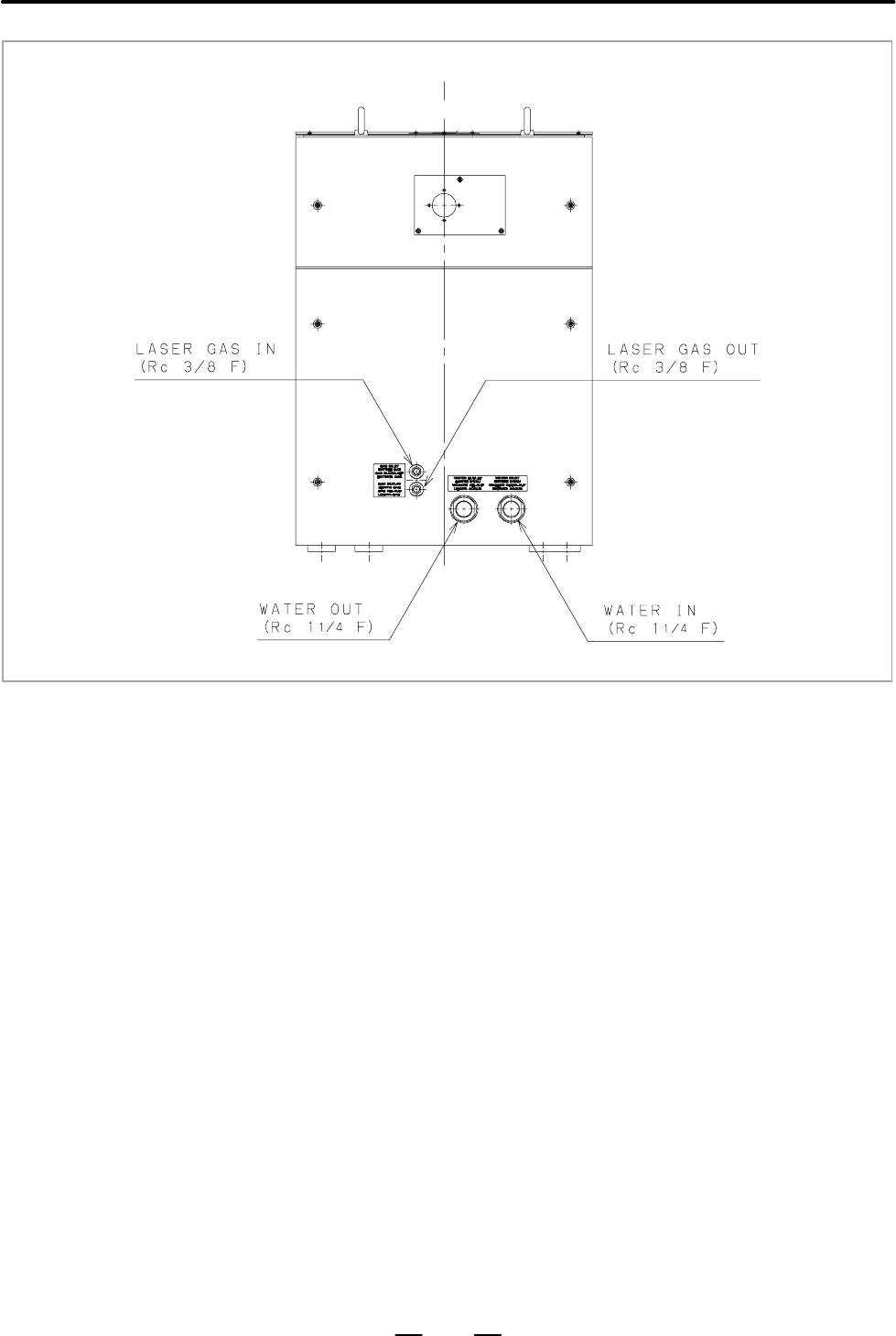
- Page 783. INSTALLATION B–70114EN/04 Fig. 3.6.4 (a) Water connection and gas connection (C1500B, C2000B) 68
- Page 79B–70114EN/04 3. INSTALLATION Fig. 3.6.4 (b) Water connection and gas connection (C2000C) 69
- Page 803. INSTALLATION B–70114EN/04 Fig. 3.6.4 (c) Water connection and gas connection (C3000C) 70
- Page 81B–70114EN/04 3. INSTALLATION Fig. 3.6.4 (d) Water connection and gas connection (C3000C) 71
- Page 823. INSTALLATION B–70114EN/04 Fig. 3.6.4 (e) Water connection and gas connection (C3000D) 72
- Page 83B–70114EN/04 3. INSTALLATION Fig. 3.6.4 (f) Water connection and gas connection (C4000A) 73
- Page 843. INSTALLATION B–70114EN/04 Fig. 3.6.4 (g) Water connection and gas connection (C6000B) 74
- Page 85B–70114EN/04 3. INSTALLATION 3.7 LASER GAS 3.7.1 Use the gas bottle of the volume of 7m3. Store the necessary number of Gas Bottle bottles according to the operation of the laser. 3.7.2 Drawing of last chapter 1 shown laser gas connection of inlet and outlet. Laser Gas Tubing Inlet and outlet fittin
- Page 863. INSTALLATION B–70114EN/04 3.8 Here explanation are given for the convenience of designing machines. LASER BEAM 3.8.1 The following figures and attached tables show the positions and Position and Tolerance tolerances of beam. of Laser Beam Exit Fig. 3.8.1 (a) Beam exit (C1500B, C2000B, C2000C, C30
- Page 87B–70114EN/04 3. INSTALLATION Fig. Position of laser beam exit Model W1 W2 W3 H C1500B, C2000B, C2000C 310"5 65 375 876"5 Short path length type C1500B, C2000B, C2000C 390"5 65 455 876"5 Long path length type C3000C, C3000D, C4000A 310"5 65 375 811"5 Short path length type C3000C, C3000D, C4000A 420"
- Page 883. INSTALLATION B–70114EN/04 3.9 The following cables should be connected to the laser. Refer to the Connecting Manual of the controller (CNC). ELECTRIC Cable connection point and clamp of cable refer to Fig. 3.9 (a) to (h). All CONNECTION cable must be used the cable inlet. Fig. 3.9 (a) Cable conne
- Page 89B–70114EN/04 3. INSTALLATION Fig. 3.9 (c) Cable connection (C2000C) Fig. 3.9 (d) Cable connection (C3000C) 79
- Page 903. INSTALLATION B–70114EN/04 Fig. 3.9 (e) Cable connection (C3000C) Fig. 3.9 (f) Cable connection (C3000D) 80
- Page 91B–70114EN/04 3. INSTALLATION Fig. 3.9 (g) Cable connection (C4000A) Fig. 3.9 (h) Cable connection (C6000B) 81
- Page 923. INSTALLATION B–70114EN/04 3.9.1 Use the cable with 4 cores. (C1500B, C2000B, C2000C, C3000C, Power Cable C3000D, C4000A) Conductor cross section must be more than 22mm2 (C1500B), 35mm2 (L1, L2, L3) (C2000B, C2000C, C3000C, C3000D, C4000A). Outer diameter of cable must be between f 22mm to f 32mm
- Page 93B–70114EN/04 3. INSTALLATION Fig. 3.9.4 (a) Detail of IF PCB 16–L Fig. 3.9.4 (b) Detail of 16i–L 83
- Page 943. INSTALLATION B–70114EN/04 D For 0–L 1) Fuse alarm signal (FAL1, FAL2) The warning signals contact of the thermal switch and circuit protector. When the contact is closed, turn off either the CNC power supply or the laser power supply ON/OFF signal. Contact capacity 220 VAC, 6A or 24VDC, 10A. 2) O
- Page 95B–70114EN/04 3. INSTALLATION 3.9.5 The diagram of safety interlock circuit is shown in Fig. (a) to (g). Terminal XT20 Terminal layout is shown in Fig. (h). Fig. 3.9.5 (a) Safety interlock circuit (C1500B) 85
- Page 963. INSTALLATION B–70114EN/04 Fig. 3.9.5 (b) Safety interlock circuit (C2000B) 86
- Page 97B–70114EN/04 3. INSTALLATION Fig. 3.9.5 (c) Safety interlock circuit (C2000C) 87
- Page 983. INSTALLATION B–70114EN/04 Fig. 3.9.5 (d) Safety interlock circuit (C3000C) 88
- Page 99B–70114EN/04 3. INSTALLATION Fig. 3.9.5 (e) Safety interlock circuit (C3000D) 89
- Page 1003. INSTALLATION B–70114EN/04 Fig. 3.9.5 (f) Safety interlock circuit (C4000A) 90
- Page 101B–70114EN/04 3. INSTALLATION Fig. 3.9.5 (g) Safety interlock circuit (C6000B) 91
- Page 1023. INSTALLATION B–70114EN/04 Fig. 3.9.5 (h) Detail of terminal XT20 1) PF1, PF2: These are the voltage release terminals of a main breaker (QF1). Impress the voltage of 24VDC. PF1: +24V PF2: 0V 2) SHL1, SHL2: When these terminals short, the shutter can be opened. It short of these terminals when shi
- Page 103B–70114EN/04 3. INSTALLATION 3.9.6 Cable shield EMC Countermeasure Install the appended Cable Shield (A04B–0811–D021) in power cable. Fig. 3.9.6 Cable shield Main power cable (AC220/200V 3f) is wrapped with CABLE SHIELD and the earth cable of CABLE SHIELD is grounded. In that case, there is no space
- Page 1044. FUNCTIONS B–70114EN/04 4 FUNCTIONS This chapter describes the internal structure, components, and operating sequence of the laser oscillator. Contents of this chapter 4.1 INTERNAL STRUCTURE . . . . . . . . . . . . . . . . . . . . . 95 4.2 COMPONENT DETAILS . . . . . . . . . . . . . . . . . . . .
- Page 105B–70114EN/04 4. FUNCTIONS 4.1 Fig. 4.1.1 (a) to (g) show the internal structure of the laser oscillator. INTERNAL STRUCTURE 4.1.1 The FANUC LASER C series consists of a laser resonator, laser excitation power supply, forced gas circulating system, pressure controller, exhaust Outline controller, CNC
- Page 1064. FUNCTIONS B–70114EN/04 Fig. 4.1.1 (a) Block diagram (C1500B) 96
- Page 107B–70114EN/04 4. FUNCTIONS Fig. 4.1.1 (b) Block diagram (C2000B) 97
- Page 1084. FUNCTIONS B–70114EN/04 Fig. 4.1.1 (c) Block diagram (C2000C) 98
- Page 109B–70114EN/04 4. FUNCTIONS Fig. 4.1.1 (d) Block diagram (C3000C) 99
- Page 1104. FUNCTIONS B–70114EN/04 Fig. 4.1.1 (e) Block diagram (C3000D) 100
- Page 111B–70114EN/04 4. FUNCTIONS Fig. 4.1.1 (f) Block diagram (C4000A) 101
- Page 1124. FUNCTIONS B–70114EN/04 Fig. 4.1.1 (g) Block diagram (C6000B) 102
- Page 113B–70114EN/04 4. FUNCTIONS 4.2 The following describes the details of each component of the FANUC LASER C series. Fig. 4.2 (a) to (l) show the internal structure. COMPONENT DETAILS (1) Resonator The resonator consists of an output mirror, rear mirror, folding mirrors, discharge tubes, power sensor un
- Page 1144. FUNCTIONS B–70114EN/04 (11) Pressure controller This unit constantly monitors the gas pressure in the discharge tubes and supplies fresh laser gas to the gas circulating system, thus maintaining a constant pressure in the discharge tubes. This unit also monitors the laser gas supply state and the
- Page 115B–70114EN/04 4. FUNCTIONS (19) Water distribution unit This unit distributes cooling water, supplied from either a chiller unit or a temperature–regulated external water supply, to each unit in the laser oscillator. For safety, the water distribution unit is equipped with a flow sensor which allows
- Page 1164. FUNCTIONS B–70114EN/04 (29) Control PCB This PCB sends the contractor open/close signal to the power magnetics cabinet, as directed by commands received from the CNC. It also notifies the CNC of the open/close status of the circuit breaker in the power magnetics cabinet. (30) Condensation sensor
- Page 117B–70114EN/04 4. FUNCTIONS Fig. 4.2 (a) C1500B internal structure (front) Fig. 4.2 (b) C1500B internal structure (rear) 107
- Page 1184. FUNCTIONS B–70114EN/04 Fig. 4.2 (c) C2000B internal structure (front) Fig. 4.2 (d) C2000B internal structure (rear) 108
- Page 119B–70114EN/04 4. FUNCTIONS Fig. 4.2 (e) C2000C internal structure (front) Fig. 4.2 (f) C2000C internal structure (rear) 109
- Page 1204. FUNCTIONS B–70114EN/04 Fig. 4.2 (g) C3000C internal structure (front) Fig. 4.2 (h) C3000C internal structure (rear) 110
- Page 121B–70114EN/04 4. FUNCTIONS Fig. 4.2 (i) Auxiliary unit internal structure (C3000C) 111
- Page 1224. FUNCTIONS B–70114EN/04 Fig. 4.2 (j) C3000D internal structure (front) Fig. 4.2 (k) C3000D internal structure (rear) 112
- Page 123B–70114EN/04 4. FUNCTIONS Fig. 4.2 (l) C4000A internal structure (front) Fig. 4.2 (m) C4000A internal structure (rear) 113
- Page 1244. FUNCTIONS B–70114EN/04 Fig. 4.2 (n) C6000B internal structure (front) Fig. 4.2 (o) C6000B internal structure (rear) 114
- Page 125B–70114EN/04 4. FUNCTION 4.3 FANUC LASER C series are controlled by CNC. When you turn on the start key (run key), start sequence and calibrate laser power automatically. OPERATION You make program of material processing only. When you turn off the SEQUENCE start key, stop sequence and oscillator st
- Page 1264. FUNCTION B–70114EN/04 After power is turned on, laser comes into PURGE=1 state. This signal is on when atmospheric pressure sensor monitors that the intra–tube pressure equals atmospheric pressure. Usually when this signal is on, purge completion lamp on operational board is lit. [SEQ20] READY OF
- Page 127B–70114EN/04 4. FUNCTION 4.4 The material processing machine using FANUC LASER C series is usually composed in the configuration shown in the figure. In the figure LASER PROCESSING the rectangular parts of the solid line are FANUC products. In the below MACHINE SYSTEM each component are explained. (
- Page 1284. FUNCTION B–70114EN/04 (4) Guide laser (Laser diode) A diode laser is used for coarse–control of the optical system axis after a light beam is output from the oscillator. This laser can also be used to identify the point to be machined. (5) Assist gas unit In laser material processing the injectio
- Page 129B–70114EN/04 5. MAINTENANCE 5 MAINTENANCE In FANUC LASER C series, periodic inspection items have been reduced, and adjustments have been made easy. To keep the oscillator in a satisfactory operating condition over a long period, however, it is necessary to carry out periodic maintenance (including
- Page 1305. MAINTENANCE B–70114EN/04 5.1 Table 5.1 lists daily inspection items. Inspect the FANUC LASER C series according to this table. When parts (including oil) have been used DAILY INSPECTION for a prescribed period, replace them quickly. Table 5.1 Daily inspection items for FANUC LASER C series Item P
- Page 131B–70114EN/04 5. MAINTENANCE 5.2 Table 5.2 shows the periodic maintenance items and the periods. The operation hour can be known from the indication of hour meter. When the PERIODIC indicated periods are more than one, employ the one whichever comes MAINTENANCE first. Table 5.2 (a) Periodic maintenan
- Page 1325. MAINTENANCE B–70114EN/04 Table 5.2 (b) Periodic maintenance items and periods Interval of maintenance (Operation hour) Item C4000A C6000B 1 Output mirror cleaning 800–2000h 800–1200h 2 Rear mirror cleaning 3 Folding mirror cleaning 3000–4000h 1000h or processing quality 4 0–shift mirror cleaning
- Page 133B–70114EN/04 5. MAINTENANCE 5.3 When opening the panels during maintenance, keep the power turn off. DETAILS OF MAINTENANCE 5.3.1 Be sure to open the panel indicated in Fig. 5.3.1 (a), (b), (c), or (d) before Maintenance Panels replacing oil or the filter during daily maintenance. and Oil Gauge Posi
- Page 1345. MAINTENANCE B–70114EN/04 Fig. 5.3.1 (c) Maintenance panel (C4000A) Fig. 5.3.1 (d) Maintenance panel (C6000B) 124
- Page 135B–70114EN/04 5. MAINTENANCE The locations of the oil gages are shown in Figs. 5.3.1 (e) to (l). These oil gages can be checked through a window without having to open the panel. Fig. 5.3.1 (e) Oil gauge of turbo blower and exhaust pump (C1500B) Fig. 5.3.1 (f) Oil gauge of turbo blower and exhaust pu
- Page 1365. MAINTENANCE B–70114EN/04 Fig. 5.3.1 (g) Oil gauge of turbo blower and exhaust pump (C2000C) Fig. 5.3.1 (h) Oil gauge of turbo blower (C3000C) 126
- Page 137B–70114EN/04 5. MAINTENANCE Fig. 5.3.1 (i) Oil gauge of exhaust pump (C3000C) Fig. 5.3.1 (j) Oil gauge of turbo blower and exhaust pump (C3000D) 127
- Page 1385. MAINTENANCE B–70114EN/04 Fig. 5.3.1 (k) Oil gauge of turbo blower and exhaust pump (C4000A) Fig. 5.3.1 (l) Oil gauge of turbo blower and exhaust pump (C6000B) 128
- Page 139B–70114EN/04 5. MAINTENANCE 5.3.2 Turbo Blower Oil D Check method Check the amount of oil in the turbo blower while referring to the figure below. The oil level should be between graduations H and L. Fig. 5.3.2 Turbo blower oil gauge Note This check should be made when the oscillator is at a rest. W
- Page 1405. MAINTENANCE B–70114EN/04 3. Clean the oil inlet, hexagonal–head screw, and O–ring by wiping with clean cloth or paper. Make sure that these parts are free of dust and lint. Put the O–ring in the groove around the hexagonal–head screw hole at the oil inlet correctly. Fit and tighten the hexagonal–
- Page 141B–70114EN/04 5. MAINTENANCE 5.3.3 Fig. 5.3.3 shows the location of the oil gauge. See also Fig. 5.3.4. Exhaust Pump Oil D Check method Watch the oil gauge, and check that the oil level is between graduations L and H. Also check whether the oil is dark. If the oil level is below L, add oil to the tur
- Page 1425. MAINTENANCE B–70114EN/04 5.3.4 Exhaust Pump Filter D Replacement method Replace the filter every 3000 hours of operation or every year of use, whichever is earlier. If the filter gets clogged, the pump output becomes low. Fig. 5.3.4 shows where the filter of a exhaust pump is located. SCREW KNOB
- Page 143B–70114EN/04 5. MAINTENANCE 5.3.5 Replace the filter every 1500 hours of operation or every 6 months of use, Exhaust System Filter whichever is earlier. Fig. 5.3.5 shows the exhaust pipe filter. None of the C1500B, C2000B, C3000C, C3000D, and C4000A is equipped with this filter. D Replacement method
- Page 1445. MAINTENANCE B–70114EN/04 10.Take out a new cartridge filter (A97L–0201–0211, AdvanTech Toyo TCG–045–SIFS) from its bag, and put a plate gasket (supplied together with the cartridge filter) on both ends of the filter. 11.Insert the cartridge filter into the housing head, and fasten it with the fas
- Page 145B–70114EN/04 5. MAINTENANCE 5.4 If the machine has not been unused for an extended period of time (three days or longer) or if the laser gas circulatory system is exposed to the AGING atmosphere (after, for example, turbo blower oil replacement), aging is required. Aging refers to heating the discha
- Page 1465. MAINTENANCE B–70114EN/04 (1) Change the settings of the following parameters. (Be sure to record the settings. The settings may differ from those in the data sheet.) To change the settings of parameters, enter MDI mode and change Parameter enable from 0 to 1 on the Setting Screen. This causes a w
- Page 147B–70114EN/04 5. MAINTENANCE D Manual method This method is possible if the machine operator’s panel provides a manual internal discharge switch. 1) From the setting screen, enter the output and the duty. 2) Press the internal discharge switch to start internal discharge. (5) When the prescribed time
- Page 1485. MAINTENANCE B–70114EN/04 5.5 To procure consumables, contact the machine builder or FANUC service center, and tell the applicable specification number listed below. MAINTENANCE PARTS 5.5.1 D Consumable parts Spare Parts Item Specification 1 Turbo blower oil kit A04B–0800–K326 2 Exhaust pump oil A
- Page 149B–70114EN/04 5. MAINTENANCE 5.5.2 Following tools are recommended for maintenance. Maintenance Tools (1) Equipment Equipment Condition Application AC voltmeter Accuracy: "2% For measuring AC power DC voltmeter Full scale: 10V, 30V For measuring DC power Accuracy: "2% Digital voltmeter Full scale: 10
- Page 1506. TROUBLESHOOTING B–70114EN/04 6 TROUBLESHOOTING The FANUC C series laser is provided with various sensors. They are always monitored by a CNC. If the oscillator becomes abnormal, the CNC promptly takes safety measures and brings the oscillator to a stop or stand–by. Contents of this chapter 6.1 CH
- Page 151B–70114EN/04 6. TROUBLESHOOTING 6.1 After identifying the following items, call the FANUC service center. In some cases, a symptom is not actually a fault in the oscillator, although CHECKING ON it looks like a fault. So, check it with the following sections. FAULTS 1. Symptoms 1 State of operation
- Page 1526. TROUBLESHOOTING B–70114EN/04 6.2 See a list of alarms in an appendix at the end of this manual. The alarm number, DGN, and parameter number (PRM NO.) vary with the CNC RESPONDING TO model. So, the FS–16L number comes first, and the FS–0L number is ALARM MESSAGES enclosed in parentheses. ON THE SC
- Page 153B–70114EN/04 6. TROUBLESHOOTING 2. Confirming operation Confirm the symptom, and call the FANUC service center. and investigating the No. Phenomenon Presumption cause cause of a fault 1 An alarm occurs before discharge The laser power supply is de- begins. fective. 2 The RF discharge current is smal
- Page 1546. TROUBLESHOOTING B–70114EN/04 3. Solution No. Cause of trouble Solution 1 External laser gas pipe ab- Improve the external pipe. The pipe normal should be installed in such a way that neither material chips nor impurities are released. There shall be no gas leak- age. 2 Gas composition ratio ab- R
- Page 155B–70114EN/04 6. TROUBLESHOOTING Alarm No. 4066 [666] Discharge anomaly (Refer to DGN = 909 to 914 [861 to 868] Pressing the HVON (start discharge) button causes the unit to start discharging. This alarm is issued, if at least one discharge tube fails to operate. No. Cause of trouble Solution 1 Anoma
- Page 1566. TROUBLESHOOTING B–70114EN/04 Alarm No. 4068 [668] Too much incident laser beam back to the resonator. (Refer to DGN = 906 [878]) This alarm is issued, if a workpiece reflects laser beam more than the rating to the laser oscillator. This can happen when the laser beam is used to drill, cut, or wel
- Page 157B–70114EN/04 6. TROUBLESHOOTING Alarm No. 4071 [671] Anomaly of assist gas (Refer to DGN = G221/bit 7 [145/bit7] When starting machining, the NC monitors for a ready signal from the assist gas supply unit in the machine. If this signal is not sent normally, the NC issues this alarm. Check the operat
- Page 1586. TROUBLESHOOTING B–70114EN/04 Alarm No. 4075 [675] Condensation (Refer to DGN = 961/bit 2 [840/bit 6]) There is a condensation sensor at the inlet of the water branch unit in the oscillator. This alarm is issued, when condensation is detected. If this alarm occurs, the alarm condition cannot be re
- Page 159B–70114EN/04 6. TROUBLESHOOTING Alarm No. 4077 [677] Overheat of beam absorber (Refer to DGN = 961/bit 7 [841/bit 3]) Laser beam is introduced into the beam absorber, when the oscillation takes place with shutter closed. This absorber is water–cooled and sends alarm when the temperature exceeds a cr
- Page 1606. TROUBLESHOOTING B–70114EN/04 Alarm No. 4080 [680] Leakage of gas tube/anomaly of exhaust pump (Refer to DGN = 905 [860]) When the RUN (pressure control start) button is pressed, the exhaust pump starts operating and expels gas from the gas circulating system to cause a low–pressure condition. Thi
- Page 161B–70114EN/04 6. TROUBLESHOOTING Alarm No. 4081 [681] Anomaly of gas pressure control (Refer to DGN = 905 [860] Pressing the RUN (pressure control start) button starts expelling air from the laser gas tube. When a specified degree of vacuum is attained, laser gas is supplied into the laser gas tube,
- Page 1626. TROUBLESHOOTING B–70114EN/04 Alarm No. 4083 [683] Shutter failure to open This alarm occurs when the shutter does not reach the correct position at a certain time (pre–flow time of assist gas) after the shutter open command. This alarm takes place in the following cases. No. Cause of trouble Solu
- Page 163B–70114EN/04 6. TROUBLESHOOTING Alarm No. 4087 [687] Shutter temperature abnormal (Refer to bit 6 of DGN 961 [bit 2 of 841].) This alarm is issued, if the temperature of the shutter mirror exceeds the limit, which is 80°C for C1500B, C2000B, C2000C, C3000C, C3000D, C4000A, or 90°C for C6000B. No. Ca
- Page 1646. TROUBLESHOOTING B–70114EN/04 Alarm No. 4089 [689] Assist gas not output (Refer to bits 0 to 2 of DGN F222 [bits 0 to 2 of 173].) This alarm is issued, if an attempt is made to radiate a laser beam, when no assist gas is selected, or an assist gas condition is not set up. Alarm No. 4090 [690] Lase
- Page 165B–70114EN/04 6. TROUBLESHOOTING Alarm No. Invertor frequency reached signal abnormal 4101, 4111 [– –] This alarm is issued, if a frequency reached signal (bit 1 of DGN 962, 963, and 964) is not received within 120 seconds after the turbo blower is started. No. Cause of trouble Solution 1 Cable conne
- Page 1666. TROUBLESHOOTING B–70114EN/04 Alarm No. 4107 [621] External reflecting mirror not installed This alarm is issued, if the beam reflecting unit is not attached with a mirror or mirror holder. No. Cause of trouble Solution 1 Reflecting mirror not Call the FANUC service center. installed 2 Switch abno
- Page 167APPENDI�
- Page 168
- Page 169B–70114EN/04 APPENDIX A. EXTERNAL VIEW A EXTERNAL VIEW Fig. A (a) C1500B (short optical path length type) Fig. A (b) C1500B (long optical path length type) 159
- Page 170A. EXTERNAL VIEW APPENDIX B–70114EN/04 Fig. A (c) C2000B (short optical path length type) Fig. A (d) C2000B (long optical path length type) 160
- Page 171B–70114EN/04 APPENDIX A. EXTERNAL VIEW Fig. A (e) C2000C (short optical path length type) Fig. A (f) C2000C (long optical path length type) 161
- Page 172A. EXTERNAL VIEW APPENDIX B–70114EN/04 Fig. A (g) C3000C (short optical path length type) Fig. A (h) C3000C (long optical path length A type) 162
- Page 173B–70114EN/04 APPENDIX A. EXTERNAL VIEW Fig. A (i) C3000C (long optical path length B type) Fig. A (j) C3000C (auxiliary unit) 163
- Page 174A. EXTERNAL VIEW APPENDIX B–70114EN/04 Fig. A (k) C3000D (short optical path length type) Fig. A (l) C3000D (long optical path length type) 164
- Page 175B–70114EN/04 APPENDIX A. EXTERNAL VIEW Fig. A (m) C4000A (short optical path length type) Fig. A (n) C4000A (long optical path length type B) 165
- Page 176A. EXTERNAL VIEW APPENDIX B–70114EN/04 Fig. A (o) C6000B 166
- Page 177B. FANUC LASER C SERIES B–70114EN/04 APPENDIX SPECIFICATIONS B FANUC LASER C SERIES SPECIFICATIONS 167
- Page 178B. FANUC LASER C SERIES SPECIFICATIONS APPENDIX B–70114EN/04 Item Contents Model C1500B C1500B C2000B C2000B C2000C C2000C (Short) (Long) (Short) (Long) (Short) (Long) Principle RF discharge excited fast axial flow CO2 laser Structure Oscillator and power source integrated Rated power 1,500W 2,000W
- Page 179B. FANUC LASER C SERIES B–70114EN/04 APPENDIX SPECIFICATIONS Item Contents Model C3000C C3000C C3000D C3000D (Short) (Long) (Short) (Long) Principle RF discharge excited fast axial flow CO2 laser Structure Oscillator and auxiliary unit separated Oscillator and power source integrated Rated power 3,0
- Page 180B. FANUC LASER C SERIES SPECIFICATIONS APPENDIX B–70114EN/04 Item Contents Model C4000A C4000A C6000B (Short) (Long) Principle RF discharge excited fast axial flow CO2 laser Structure Oscillator and power source integrated Rated power 4,000W 6,000W Max power 4,000W 6,000W Pulse power peak 5,000W (<5
- Page 181B–70114EN/04 APPENDIX C. ERROR CODE LIST C ERROR CODE LIST (1/2) Number FS–16L, FS–0L Contents Alarm level 16iL 4061 661 Anomaly in AD converter 1 ALARM 1 4062 662 Anomaly in AD converter 2 ALARM 1 4063 663 Anomaly in laser power supply unit ALARM 2 4065 665 Anomaly in shutter action ALARM 2 4066 66
- Page 182C. ERROR CODE LIST APPENDIX B–70114EN/04 (2/2) Number FS–16L, FS–0L Contents Alarm level 16iL 4085 685 Decrease of laser output A warning has occurred. It can be reset. 4087 687 Overheat in shutter mirror ALARM 2 4088 688 The discharge tube voltage is low. ALARM 1 4089 689 Selection signal of assist
- Page 183B–70114EN/04 APPENDIX D. FANUC SERVICE NETWORK D FANUC SERVICE NETWORK FANUC LTD Headquarters: Oshino–mura, Yamanashi Prefecture, 401–0597, Japan Phone 555–84–5555 Fax 555–84–5512 Country code 81 Service division: 5–1, Asahigaoka 3–Chome, Hino–shi, Tokyo 191, Japan Phone 425–84–1111 Fax 425–85–0954
- Page 184E. GLOSSARY APPENDIX B–70114EN/04 E GLOSSARY Name Meaning Access panel That protective component of a housing or enclosure which, when removed or shifted, can cause exposure to laser radiation. AEL Accessible emission level Maximum accessible emission level set up for each class of laser products Al
- Page 185B–70114EN/04 APPENDIX E. GLOSSARY Name Meaning Laser safety standard Standard to protect human bodies from hazards resulting from laser beams in view of use of lasers and about laser products for sale Linear Polarization in which a plain of polarization is at a constant angle with the axis Polarizat
- Page 186E. GLOSSARY APPENDIX B–70114EN/04 Name Meaning Sequence A succession of steps carried out in a prescribed order Stimulated emission Emission of light stimulated by incident light and having the same frequency, phase, and polarization state as the incident light Target Jig used to radiate and positio
- Page 187B–70114EN/04 Index ƠAơ ƠGơ Aging, 135 Gas bottle, 75 Aging method, 135 Gas pipe, 75 Applicable models, 3 Glossary, 174 Ground cable, 82 ƠBơ Base of oscillator, 54 ƠHơ High temperature, 20 Beam divergence, 77 High voltage, 11 Beam guide, 77 ƠIơ ƠCơ I/O signal cable, 82 Checking on faults, 141 Inappos
- Page 188INDEX B–70114EN/04 ƠPơ ƠTơ Packing, 49 Tolerance of beam direction, 77 Periodic maintenance, 121 Toxic fume, 19 Plumbing, 67 Transportation, 48 Position and tolerance of laser beam exit, 76 Troubleshooting, 140 Power cable (L1, L2, L3), 82 Turbo blower oil, 129 Power source, 45 ƠRơ ƠWơ Related manua
- Page 189Revision Record FANUC LASER C series OPERATOR’S MANUAL (B–70114EN) 04 Jun., 2000 D Addition of C2000C, C3000D, C4000A and C6000B D Addition of C3000C 03 Jul., 1996 D Correction of errors D Addition of C2000B 02 Apr., 1995 D Correction of errors 01 Dec., 1994 Edition Date Contents Edition Date Conten
- Page 190
- Page 191EUROPEAN HEADQUARTERS – BELGIUM / NETHERLANDS GRAND-DUCHÉ DE LUXEMBOURG GE Fanuc Automation Europe S.A. GE Fanuc Automation Europe S.A. - Netherlands Branch - Zone Industrielle Postbus 7230 - NL-4800 GE Breda L-6468 Echternach Minervum 1603A - NL-4817 ZL Breda ( (+352) 727979 - 1 ( (+31) 76-5783 201
- Page 192• No part of this manual may be reproduced in any form. • All specifications and designs are subject to change without prior notice. The export of this product is subject to the authorization of the government of the country from where the product is exported. In this manual we have tried as much as
- Page 193TECHNICAL REPORT NO.TML 01/005E Date. JUN. 11.2001 General Manager of Laser Laboratory Correction of the manual of FANUC LASER C series 1. Communicate this report to: ○ Your information ○ GE Fanuc-N, GE Fanuc-E FANUC Robotics CINCINNATI MILACRON ○ Machine tool builder Sales agency End user 2. Summar
- Page 194Corrections of the periodic maintenance 1.Type of applied technical documents Name FANUC LASER C series OPERATOR'S MANUAL Spec. No. / Ver. B-70114EN/04 2.Summary of change Group Name / Outline New, Add Applicable Correct, Del Date Basic Function Optional Function Unit Maintenance Parts Notice Correc
- Page 195In FANUC LASER C series OPERATOR’S MANUAL B-70114EN/04, interval of turbo blower oil change is corrected on page 121,122. Table 5.2(a) Periodic maintenance items and periods (Page 121) Interval of maintenance (Operation hour) C2000B C3000C C1500B C2000C C3000D True : 1000h or inferior turbo blower o
- Page 196Corrections of the periodic maintenance 1.Type of applied technical documents Name FANUC LASER C series MAINTENANCE MANUAL Spec. No. / Ver. B-70115EN/03 2.Summary of change Group Name / Outline New, Add Applicable Correct, Del Date Basic Function Optional Function Unit Maintenance Parts Notice Corre
- Page 197In FANUC LASER C series MAINTENANCE MANUAL B-70115EN/03, the interval of turbo blower oil change is corrected on page 112,113. Table 5.2(a) Periodic maintenance items and periods (Page 112) Interval of maintenance (Operation hour) C2000B C3000C C1500B C2000C C3000D True : 1000h or inferior turbo blo