Series 15i/150i-Model A Remote Buffer Descriptions Page 15
Descriptions
B-63322EN-1/01 3. ELECTRICAL INTERFACE
-9-
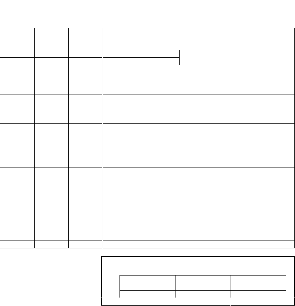
3) Signal description
Signal
name
RS-232-C
circuit
number
Input/
output
Description
SD 103 Output Send data
RD 104 Input Receive data
See “3.1” for the bit configuration.
RS 105 Output Request to send
It is used to inform whether the remote buffer is ready to receive data or not.
When the ER signal is on and this signal is on, the remote buffer is ready to
receive data.
CS 106 Input Clear to send
It is used to know the busy status at the host computer. When the DR signal
is on and this signal is on, the host computer is regarded as being ready to
receive data.
DR 107 Input Data set ready
When this signal is on, it is considered that the preparation at the host
computer has been completed. Generally, it is connected to the ER signal of
the host computer. When this signal is off during data transmission, an
alarm occurs.
Always connect it to the ER signal of CNC side when this signal is not used.
ER 108.2 Output Data terminal ready
When this signal is on, it is considered that the remote buffer is in ready
condition.
In general, it is connected to the ER signal at the host computer. If it is
turned off during transmission of data, an alarm occurs. If this signal is not
used, always connect this to the ER signal at the CNC side.
CD 109 Input Received line signal detector
This signal is not used for connection to the host computer. Thus, connect it
to the ER signal of remote buffer side.
SG 102 Grounding for signal
FG 101 Grounding for protection
NOTE
Turn on or off signal according to the following:
-3 V or less +3 V or more
Function OFF ON
Signal Condition Marking Spacing
Contents Summary of Series 15i/150i-Model A Remote Buffer Descriptions
- Page 1GE Fanuc Automation Computer Numerical Control Products Series 15i / 150i – Model A Remote Buffer Descriptions Manual B-6322EN-1/01 1999
- Page 2Warnings and notices for GFLE-003 this publication Warning In this manual we have tried as much as possible to describe all the various matters. However, we cannot describe all the matters which must not be done, or which cannot be done, because there are so many possibilities. Therefore, matters wh
- Page 3B-63322EN-1/01 PREFACE PREFACE Applicable product name The models covered by this manual, and their abbreviations are: Product name Abbreviations FANUC Series 15i-MA 15i-MA Series 15i FANUC Series 150i-MA 150i-MA Series 150i Related manuals The table below lists manuals related to MODEL A of Series
- Page 4B-63322EN-1/01 CONTENTS PREFACE ................................................................................................................ p-1 1. GENERAL............................................................................................................. 1 2. INTERFACE BETWEEN REMOTE B
- Page 5CONTENTS B-63322EN-1/01 8. DATA INTERFACE .......................................................................................... 51 8.1 DATA PART ............................................................................................................................ 52 8.2 INTERFACE OF DATA
- Page 6
- Page 7B-63322EN-1/01 1. GENERAL 1 GENERAL The remote buffer for FANUC Series 15i/150i-MODEL A is an option and is used to allow a large number of data to be continuously supplied to the CNC at high speed by connecting it to the host computer or I/O device through a serial interface. RS-232-C/RS-422 Host 1
- Page 82. INTERFACE BETWEEN REMOTE BUFFER AND HOST COMPUTER B-63322EN-1/01 2 INTERFACE BETWEEN REMOTE BUFFER AND HOST COMPUTER -2-�
- Page 9B-63322EN-1/01 2. INTERFACE BETWEEN REMOTE BUFFER AND HOST COMPUTER 2.1 ELECTRICAL INTERFACE The following which interfaces are provided as standard specifications. 1) RS-232-C interface 2) RS-422 interface (Note 1) RS-232-C RS-422 Interface Serial voltage interface Balance transmission serial (star
- Page 102. INTERFACE BETWEEN REMOTE BUFFER AND HOST COMPUTER B-63322EN-1/01 2.2 SOFTWARE INTERFACE The following four protocols for communication between the remote buffer and host computer are provided. The protocol meeting the requirement of specifications of connection device can be selected by setting a
- Page 11B-63322EN-1/01 3. ELECTRICAL INTERFACE 3 ELECTRICAL INTERFACE -5-�
- Page 123. ELECTRICAL INTERFACE B-63322EN-1/01 3.1 TRANSMISSION SYSTEM It is the start-stop system for adding the start bit before and stop bit after the information bits, respectively. The format for adding one parity bit to each byte of data to be transmitted is also allowed. 1) Format with no parity bit
- Page 13B-63322EN-1/01 3. ELECTRICAL INTERFACE 3.2 RS-232-C INTERFACE 1) Connection between devices CNC remote buffer board Host computer (example) (DBM-25S) JD5L 1 FG (PCR-E20LMDETZ-SL) 14 2 SD 15 1 RD 11 SD 3 RD 16 2 0V 12 0V 4 RS 17 3 DR 13 ER 5 CS 18 4 0V 14 0V 6 DR 19 5 CS 15 RS 7 SG 20 ER 6 0V 16 0V 8
- Page 143. ELECTRICAL INTERFACE B-63322EN-1/01 2) General diagram of signal connection CNC Host computer 11 Output SD SD 1 Input RD RD 15 RS RS 5 CS CS 13 ER ER 3 DR DR 7 CD CD 0V SG FG Note) When no CS is used, short-circuit it with the RS. However, when the protocol A or expansion protocol A is used, perf
- Page 15B-63322EN-1/01 3. ELECTRICAL INTERFACE 3) Signal description RS-232-C Signal Input/ circuit Description name output number SD 103 Output Send data See “3.1” for the bit configuration. RD 104 Input Receive data RS 105 Output Request to send It is used to inform whether the remote buffer is ready to r
- Page 163. ELECTRICAL INTERFACE B-63322EN-1/01 3.3 RS-422 INTERFACE 1) Connection between devices CNC remote buffer board Host computer (example) JD6L 1 FG (PCR-E20LMDETZ-SL) 20 2 21 1 RD 11 SD 3 22 *SD 2 *RD 12 *SD 4 SD 23 3 RT 13 TT 5 24 *RD 4 *RT 14 *TT 6 RD 25 *RS 5 CS 15 RS 7 RS 26 *RT 6 *CS 16 *RS 8 R
- Page 17B-63322EN-1/01 3. ELECTRICAL INTERFACE 2) General diagram of signal connection CNC Host computer 11 SD SD Output 12 *SD *SD 1 RD RD Input 2 *RD *RD 15 RS RS 16 *RS *RS 5 CS CS 6 *CS *CS 17 TR TR 18 *TR *TR 7 RR RR 9 *RR *RR 13 TT TT 14 *TT *TT 3 RT RT 4 *RT *RT 8 0V SG FG Note) NOTE Connect the FG p
- Page 183. ELECTRICAL INTERFACE B-63322EN-1/01 3) Signal description RS-232-C Signal Input/ circuit Description name output number SD 103 Output Transmission data See “3.1” for the bit configuration. RD 104 Input Reception data RS 105 Output Transmission request It is used to inform whether the remote buffe
- Page 19B-63322EN-1/01 4. PROTOCOL A 4 PROTOCOL A It is used for the handshake system where the communication between the remote buffer and host computer repeats transmission/reception each other. -13-�
- Page 204. PROTOCOL A B-63322EN-1/01 4.1 MESSAGE FORMAT The information (character-string) exchanged between the remote buffer and host computer is called “message”. The general type of message is shown as below: Message 2 byte 3 byte Variable length (it can be omitted.) 1 byte / Sum Command Data part ETX /
- Page 21B-63322EN-1/01 4. PROTOCOL A 4.3 COMMUNICATION SYSTEM It is used to perform communication between the remote buffer and host computer. When the both are ready to operate after power on, the communication starts from the transmission of remote buffer and reception of host computer and then the transm
- Page 224. PROTOCOL A B-63322EN-1/01 (4) Switching from reception to transmission The remote buffer waits for Tx msec (parameter setting time) and moves to the transmission process after completion of reception. When there is no transmission after waiting another parameter (Tp seconds), it is considered tha
- Page 23B-63322EN-1/01 4. PROTOCOL A 4.4 COMMAND 4.4.1 Command Table Commands used in the protocol A are described below: Origin station R: Remote buffer H: Hoast computer Origin Executed command Command Functions Data part station at CNC side SYN R Initialization command Meaningless SYN It is used to comma
- Page 244. PROTOCOL A B-63322EN-1/01 Origin Executed command Command Functions Data part station at CNC side EOD H Response corresponding to GTD Meaningless Transmit this command when the GTD has been received while the transmission of NC data has been completed. CLB H Buffer clear Meaningless It can be tra
- Page 25B-63322EN-1/01 4. PROTOCOL A 4.4.2 Description of Data Part Data part of message is of variable length. Up to 4096 and 72 bytes can be received/transmitted in the case of
and the others, respectively. 1) Data part of SAT Byte Default value Meaning and code position (hexadecimal) 1 Switching of - Page 264. PROTOCOL A B-63322EN-1/01 Byte Default value Meaning and code position (hexadecimal) 41 - 44 Unit for the boring time (four digits in 0000 hexadecimal) Setting parameter P2 to 1 sets the unit for the boring time to 0.1 seconds. 15 0 0 0 0 0 0 0 0 0 0 0 0 0 0 P2 0 0 45 - 46 Note) 00 Code to be con
- Page 27B-63322EN-1/01 4. PROTOCOL A a) Protocol A Section to be converted // SUM DAT Data ETX // b) Expansion protocol A Section to be converted // Data No SUM ETX //
The host computer handles an EOB code in an NC program as “;” and transmits it to the CNC as is. When ‘3’ and ‘B’ (= 3BH) a - Page 284. PROTOCOL A B-63322EN-1/01 4) Data part of SDI Byte Meaning position 1-2 2-byte hexadecimal display of 8-bit contents of DI (PMC address: G152) 3 - 72 Not used (it can be omitted.) 1) Data part of SDO Byte Meaning position 1-2 2-byte hexadecimal display of 8-bit contents of DO (PMC address: F152)
- Page 29B-63322EN-1/01 4. PROTOCOL A 4.5 PARAMETER TABLE Parameters which can be set in the data part of SET command are shown as below: On turning Parameter Meaning Unit Range on power Nb Number of bytes of minimum buffer empty area on transmission of Byte 1 - 4000 2000 GTD (Note 1) No Maximum amount of ov
- Page 304. PROTOCOL A B-63322EN-1/01 4.6 ERROR PROCESS 1) Open-line error When the following error occurs, it may be an open line error. Restart the initialization of remote buffer for recovering the line. When the line is recovered, it waits for transmission of SYN and is SYN wait status. The procedures ar
- Page 31B-63322EN-1/01 4. PROTOCOL A 4.7 STATUS TRANSITION The status transition diagram of remote buffer is shown as below: Turning on power Non-completed status of operation preparation 0 After 2 msec SYN reception RDY reception Line error Note 1 Reset status Open line status 1 4 NC reset NC reset Recepti
- Page 325. EXPANSION PROTOCOL A B-63322EN-1/01 5 EXPANSION PROTOCOL A It allows the NC data between the remote buffer and host computer to be efficiently transferred by adding the high-speed reception function to the protocol A. -26-�
- Page 33B-63322EN-1/01 5. EXPANSION PROTOCOL A 5.1 COMMUNICATION SYSTEM The expansion protocol A is the same as the protocol A excluding the transmission of NC data. The expansion protocol A mode is initiated after the
is output to the host computer by the remote buffer according to the data request f - Page 345. EXPANSION PROTOCOL A B-63322EN-1/01 5.2 DATA PACKET FORMAT The NC data is transferred to the remote buffer using the following format by the host computer after receiving the
. When the NC data transmitted becomes multiple packets, the packets can be transmitted in order without waiting the - Page 35B-63322EN-1/01 5. EXPANSION PROTOCOL A b) End packet : FFh The end packet is transmitted by setting the packet No. to FFh. The data part of end packet is considered to be the effective data. However, the end packet received after transmitting
ignores the data part. This allows the expansion pr - Page 365. EXPANSION PROTOCOL A B-63322EN-1/01 5.3 MONITOR PACKET FORMAT The monitor packets transmitted from the remote buffer to the host computer are shown as below. All packets have the fixed length consisting of 5 bytes. 1) Stop request CAN Meaningless Checksum End code ( 18h ) (20h ) ( 2 b y t e ) ( 0
- Page 37B-63322EN-1/01 5. EXPANSION PROTOCOL A 3) Interruption request DC3 Meaningless Checksum End code (93h ) ( 20h ) ( 2 b y t e ) ( 0Dh ) The interruption request is transmitted to the host computer by the remote buffer when the reception buffer may become overflown. The host computer should interrupt t
- Page 385. EXPANSION PROTOCOL A B-63322EN-1/01 5.4 COMMUNICATION EXAMPLE 1) Normal Remote buffer Host computer < GTD > Packet (0) (1 ) Packet (2 ) Packet (3 ) Packet Fh) c ket (0F End pa < SA T> T> < SE -32-�
- Page 39B-63322EN-1/01 5. EXPANSION PROTOCOL A 2) Stop request Remote buffer Host computer < GTD > (0) Packet ( 1) Packet RESET t (2) Pa cke "CAN " ) (0FFh acket En d P y data) (Dumm < RST > S> < AR < SAT > T> < SE -33-�
- Page 405. EXPANSION PROTOCOL A B-63322EN-1/01 3) Retransmission (i) Remote buffer Host computer < GTD > (0) Packet Checksum error (1) Packet detection (2) Packet "NAK" (1) Retransmit from (1) Packet the packet (1) (2) Packet (3) Packet h) ck et (0FF End pa < SA T> T> < SE -34-�
- Page 41B-63322EN-1/01 5. EXPANSION PROTOCOL A 3) Retransmission (ii) Remote buffer Host computer < GTD > (0) Packet e t (1) Pack (2) Packet (3) Packet Checksum error detection Fh) ac ke t (0 F End P "NAK" (4) h) ck et (0FF End Pa < SAT > T> < SE -35-�
- Page 425. EXPANSION PROTOCOL A B-63322EN-1/01 3) Retransmission (iii) Remote buffer Host computer < GTD > (1) Packet No. Packet Out-of-order detection (2) Packet " N AK" (0) (0) Packet (1) Packet Packet No. (3) Out-of-order Packet detection FFh) cket (0 End pa " N AK" (2) (2) Packet (3) Packet FFh) cket (0
- Page 43B-63322EN-1/01 5. EXPANSION PROTOCOL A 4) Interruption → Restart Remote buffer Host computer < GTD > (0) Packet (1) Packet (2) Empty buffer Packet Remaining less than 2 Packet s (3) Packet "DC3" Empty buffer Remaining more than 3 Packet s " DC 1" ) (0FFh acket End P < SAT > T> < SE -37-
- Page 445. EXPANSION PROTOCOL A B-63322EN-1/01 5) Interruption → Start Remote buffer Host computer < GTD > (0) Packet Empty buffer Remaining (1) Packet one block (3) Packet "DC3" RESET "CAN " Transmit the end packet for ending the expansion protocol A although (0 FFH) the DC3 is acket End P currently being
- Page 45B-63322EN-1/01 5. EXPANSION PROTOCOL A 6) Interruption → Retransmission Remote buffer Host computer < GTD > (0) Packet (1) Packet Empty buffer Remaining one block Transmit only an "DC3" error packet since Checksum error the DC3 is receiving data. detection e t ( 2) Pack Restart transmission of packe
- Page 465. EXPANSION PROTOCOL A B-63322EN-1/01 7) Time-out detection Remote buffer Host computer < GTD > (0) Packet Time-out detection < SYN > > < SYN < RDY > < RDY > < SAT > > < SET NOTE The time-out monitoring period lasts until the next one packet is received immediately after output of
. After that - Page 47B-63322EN-1/01 6. PROTOCOL B 6 PROTOCOL B The protocol B is used to control the communication between the remote buffer and host computer by the control code. -41-�
- Page 486. PROTOCOL B B-63322EN-1/01 6.1 COMMUNICATION SYSTEM The communication system can be in either of two settings, one in which the CNC reset/alarm state is posted to the host and the other in which it is not posted. When ETX (bit 3 of parameter No. 5000) is 1, the system is in the setting in which th
- Page 49B-63322EN-1/01 6. PROTOCOL B (7) The remote buffer transmits the DC3 code when the data read is completed. The end of data read is indicated by the detection of ER or NC reset. (8) The host computer stops transmission of data. 2) When the remote buffer sends data (punch-out) (Fig. A) 10 ms or more 1
- Page 506. PROTOCOL B B-63322EN-1/01 (1) The remote buffer transmits the DC2 code. (2) The remote buffer then transmits punch-out information. (3) If the processing speed of the host computer is not high enough to handle arriving data, perform one of the following: (a) Turn the CS signal of the remote buffe
- Page 51B-63322EN-1/01 6. PROTOCOL B 1) When the remote buffer is neither receiving nor transmitting data CNC power-on Reset or alarm Reset or alarm Reset or alarm ER (output) RS (output) SYN or NAK SD (output) RD (input) DR (input) CD (input) CS (input) Ignored period Valid period Ignored period The “SYN”
- Page 526. PROTOCOL B B-63322EN-1/01 (1) The remote buffer transmits the DC1 code. (2) Upon receiving the DC1 code, the host computer shall start transmitting data to the remote buffer. (3) Once the amount of free space in the remote buffer falls below the specified value, the remote buffer transmits the DC
- Page 53B-63322EN-1/01 6. PROTOCOL B (Fig. B) Reset or alarm ON ER (output) ON RS (output) DC2 DC4 (5) SYN or (1) (2) NAK SD (output) DC3 DC1 (3) (4) RD (input) DR (input) CS (input) (1) The remote buffer transmits the DC2 code. (2) The remote buffer starts transmitting punch-out data. (3) If data processin
- Page 546. PROTOCOL B B-63322EN-1/01 6.2 CONTROL CODE The control code is as shown below regardless of the ISO, EIA, and Binary data: Code (hexadecimal) Control Function Bit 2 of parameter Bit 2 of parameter code No. 5000 = 0 No. 5000 = 1 DC1 Starts host transmission. 11H 11H DC3 Stops host transmission. 93
- Page 55B-63322EN-1/01 6. PROTOCOL B 6.4 ALARM AND RESET OF CNC Once an alarm has been issued in the CNC, or upon the CNC being reset, the remote buffer transmits the DC3 code, then: (1) When the CNC reset/alarm state is not to be posted to the host (parameter No. 5003 bit 3 = 0) Turns off the ER signal, th
- Page 567. EXPANSION PROTOCOL B (RS-422) B-63322EN-1/01 7 EXPANSION PROTOCOL B (RS-422) The expansion protocol B is a protocol used to enable high-speed transmission with a simple protocol. The communication system is the same as that of protocol B. However, the overrun value after transmission of DC3 is li
- Page 57B-63322EN-1/01 8. DATA INTERFACE 8 DATA INTERFACE -51-�
- Page 588. DATA INTERFACE B-63322EN-1/01 8.1 DATA PART Data received from the host computer is largely classified into two parts, namely the control part and data part. With the protocol B/expansion protocol B, all data received from the host computer become the data part. See the following figure for the d
- Page 59B-63322EN-1/01 9. BINARY INPUT OPERATION FUNCTION 9 BINARY INPUT OPERATION FUNCTION -53-�
- Page 609. BINARY INPUT OPERATION FUNCTION B-63322EN-1/01 9.1 FUNCTION EXPLANATION Once a single "G05;" block is specified in normal NC command format, operation can be performed by specifying desired move data and auxiliary functions in the following format. By specifying zero for all of the travel distanc
- Page 61B-63322EN-1/01 9. BINARY INPUT OPERATION FUNCTION (4) The travel distance along each axis must be specified in the following units. (Negative travel distances must be in two’s- complement form.) IS_A IS_B IS_C IS_D IS_E Unit Millimeter 0.01 0.001 0.0001 0.00001 0.000001 mm machine Inch 0.001 0.0001
- Page 629. BINARY INPUT OPERATION FUNCTION B-63322EN-1/01 • Bit 3 of parameter No. 7609 = 1 ... Uses auxiliary functions. (The data length is [2 * N + 5] bytes.) (7) When the parameter is set to use auxiliary functions, specify the auxiliary functions to be used, using parameter No. 2034, as follows: • "0".
- Page 63B-63322EN-1/01 9. BINARY INPUT OPERATION FUNCTION 9.2 TRANSFER RATE After every unit time set for the appropriate parameter, the CNC extracts data of 2 * N + n bytes (where N is the number of axes, n is equal to 1 when auxiliary functions are not used and 5 when they are used.) from the remote buffe
- Page 649. BINARY INPUT OPERATION FUNCTION B-63322EN-1/01 9.3 NOTES NOTE 1 In binary input operation mode, any modal commands (such as G00, G02, G03, and G90) before the G05 block are disabled, and are executed as linear interpolation G01 based on the command data format (equivalent to linear incremental co
- Page 65B-63322EN-1/01 10. PARAMETER 10 PARAMETER The following describes the parameters related to the remote buffer. #7 #6 #5 #4 #3 #2 #1 #0 0000 XXX EIA NCR ISP CTV TVC [Input section] Setting input [Data type] Bit type #0 TVC Specifies whether TV check is performed. 0: Do not perform. 1: Perform. #1 CTV
- Page 6610. PARAMETER B-63322EN-1/01 10.1 INPUT DEVICE NUMBER 0020 Interface number of input device for foreground [Input type] Setting input [Data type] Integer [Valid data range] 0 to 16 Set the interface No. of an input device for the foreground. For the remote buffer, set a value of 10. 0021 Interface n
- Page 67B-63322EN-1/01 10. PARAMETER 10.2 EXCLUSIVE PARAMETER FOR REMOTE BUFFER #7 #6 #5 #4 #3 #2 #1 #0 5000 0 CDC ETX TCC ECH 422 [Input type] Parameter input [Data type] Bit NOTE When this parameter is specified, the power must be turned off and then on again for the parameter settings to take effect. #0
- Page 6810. PARAMETER B-63322EN-1/01 When this parameter is set to 1, the settings of the following parameters also became effective when the power is turned off, then back on: No. 5070, 5072, 5073, 5082, 5083 #4 CDC : CD (Signal quality detection) for RS-232-C interface 0 : is checked 1 : is not checked Mi
- Page 69B-63322EN-1/01 10. PARAMETER (2) The TT signal from the CNC is connected to the RT signal for the host, and the TT signal from the host is connected to the RT signal for the CNC, in both cases via cables. (3) A synchronizing clock, the same as the baud rate clock, is output from the TT pins. JIS ref
- Page 7010. PARAMETER B-63322EN-1/01 5072 RS-422 Number of stop bits (Remote buffer) [Input type] Setting input [Data type] Integer [Valid data range] 1 to 2 Set the number of stop bits of the RS-422 device of the remote buffer. NOTE When this stop bit is set to 1, the parity bit is also provided. 5073 RS-4
- Page 71B-63322EN-1/01 10. PARAMETER NOTE In the case when the protocol A/expansion protocol A were selected, if the following parameters are modified, they become valid after the power is turned off and then on. No. 5070, 5072, 5073 5081 RS-232-C Specification of I/O device (Remote buffer) [Input type] Set
- Page 7210. PARAMETER B-63322EN-1/01 Set the baud rate of the RS-232-C device of the remote buffer. Setting value baud rate Setting value baud rate 1 50 7 600 2 100 8 1200 3 110 9 2400 4 150 10 4800 5 200 11 9600 6 300 12 19200 5084 RS-232-C Selection of protocol (Remote buffer) NOTE When this parameter is
- Page 73B-63322EN-1/01 10. PARAMETER 10.3 PARAMETERS RELATED TO BINARY INPUT OPERATION 2010 Delay time of strobe signals MF, SF, TF, and BF [Input section] Parameter input [Data type] Integer type [Unit of data] msec [Valid data range] 0 to 32767 Set the time from the point an M, S, T, or B code is sent unt
- Page 7410. PARAMETER B-63322EN-1/01 #7 #6 #5 #4 #3 #2 #1 #0 7609 RAX RDS [Input section] Parameter input [Data type] Bit type #2 RDS The data format for the travel distance along an axis in remote buffer binary input operation mode is: 0: Special format 1: General format #3 RAX In remote buffer binary inpu
- Page 75B-63322EN-1/01 10. PARAMETER TM2 TM1 TM0 Unit time 1 0 0 1 msec 0 0 1 2 msec 0 1 0 4 msec 0 0 0 8 msec 0 1 1 16 msec 7635 Number of axes in a single block that can accept commands (remote buffer) [Input section] Parameter input [Data type] Integer type [Valid data range] 0 to number of controlled ax
- Page 7611. ALARM B-63322EN-1/01 11 Error code ALARM Message Description PS0010 IMPROPER G-CODE An unavailable G code is specified. PS0011 IMPROPER NC-ADDRESS An address that cannot be specified in an NC statement is specified. Or, parameter No. 1020 is not specified. PS0012 INVALID BREAK POINT OF Data that
- Page 77B-63322EN-1/01 12. MAINTENANCE 12 MAINTENANCE 12.1 LED INDICATIONS The arrangement of the LEDs on the R.B. board is as shown in the 1 figure on the right. STATUS LED : Green The upper two LEDs (green) 2 : Red indicate the current state of the A software. B ALARM LED The lower three LEDs (red) C indi
- Page 7812. MAINTENANCE B-63322EN-1/01 12.1.2 System Errors When the LEDs are in any of the statuses shown below, there is a system error. For recovery, the board must be turned off then on again. The hardware may have to be replaced in some causes. Table 12.1.2 (a) LED (green) indications and their meaning
- Page 79B-63322EN-1/01 12. MAINTENANCE Table 12.1.2 (b) LED (red) indications and their meanings (ALARM LED) No. LED (red) indication Meaning A 1 This board is reset. It is not activated by the main CPU. 2 3 B 1 L-BUS bus error An error occurred inside this printed circuit board. 2 The printed circuit board
- Page 8012. MAINTENANCE B-63322EN-1/01 12.2 MATERIAL FOR REMOTE BUFFER TROUBLESHOOTING NOTE For an explanation of the logical slot number of the R.B. (remote buffer) board, see "Determining the Logical Slot Number of the Remote Buffer Board," below. No. External phenomenon Investigation method 1 Operation d
- Page 81B-63322EN-1/01 12. MAINTENANCE No. External phenomenon Investigation method 3 (1) SR807 (1) A required parameter is out of range. PARAMETER SETTING ERROR 1 Baud rate: parameter 5073 = 1 to 15, 5083=1 to 12 2 Number of stop bits: parameter 5072 or 5082 = 1 or 2 3 Protocol type: parameter 5074 or 5084
- Page 8212. MAINTENANCE B-63322EN-1/01 12.3 DETERMINING THE LOGICAL SLOT NUMBER OF THE REMOTE BUFFER BOARD 12.3.1 Determining the Logical Slot Number on the Screen Displayed at the Time a System Alarm Occurs Display hardware information 1 (display of F-BUS slot information), 3$*( 3$*( shown below, using the
- Page 83B-63322EN-1/01 12. MAINTENANCE 12.3.2 Determining the Logical Slot Number on the System Configuration Screen Once the system has started normally, the logical slot number of the remote buffer printed circuit board can be determined by displaying the module configuration screen from the system config
- Page 84B-63322EN-1/01 INDEX Input device number 60 A Interface between remote buffer and host computer 2 Alarm 70 Interface of data part 52 Alarm and reset of CNC 49 L B LED indications 71 Binary input operation function 53 Buffer control 48 M Maintenance 71 C Material for remote buffer troubleshooting 74
- Page 85Revision Record FANUC Series 15i/150i-MODEL A Remote Buffer DESCRIPTIONS (B-63322EN-1) 01 Jul., ’99 Edition Date Contents Edition Date Contents