Power Mate H Startup Guide Page 54
Startup Guide
GFK-1383A Chapter 5 Configuring the Power Mate H 5 - 7
5
Identifying the Motor
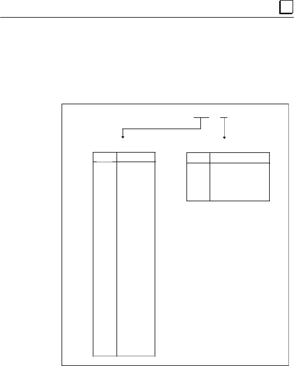
For proper setup, the Power Mate H requires information that is provided by the model number of
the motor. This model number is located on the tag affixed to each motor. Figure 5-1 breaks
down the motor number into components and identifies the elements required as setup parameters
(Parameter #2020 in Table 5-1).
Figure 5 - 1. Motor Type and Encoder Type Definition
Motor Model: A06B-xxxx-Byzz
Identifies the Motor Encoder Type
75
75
77
77
78
88
Serial Encoder Type
Alpha 64k Absolute
Beta 32k Absolute
Alpha 64k Incremental
Beta 32k Incremental
Beta 8k Absolute
Alpha 1M Absolute
zz
Motor Type
xxxx
0031
0032
0033
0034
0101
0102
0106
0113
0121
0123
0126
0127
0128
0142
0143
0145
0146
0147
0148
0151
0152
0153
0157
0158
0176
0177
0178
0371
0372
0373
0561
0562
0564
0571
0572
35
36
33
34
35
36
34
13
7
15
8
16
17
18
19
10
27
20
21
28
22
23
30
29
3
4
5
61
46
62
56
57
58
59
60
Identifies the Motor Type Number
Contents Summary of Power Mate H Startup Guide
- Page 1GE Fanuc Automation PowerMotion™ Products Power Mate H Startup Guide GFK - 1383A April 1997
- Page 2GFL-001 Warnings, Cautions, and Notes as Used in this Publication Warning Warning notices are used in this publication to emphasize that hazardous voltages, currents, temperatures, or other conditions that could cause personal injury exist in this equipment or may be associated with its use. In situ
- Page 3Preface This guide provides a quick, easy way to get the Power Mate H functioning, by leading you step- by-step through the process, beginning with unpacking the Power Mate H and ending with generating motion. Along the way, you will become familiar with the Power Mate H control and associated servo
- Page 4Preface Cabling Typical cables (when supplied by GE Fanuc) used with the Power Mate H are: FANUC Part GE Fanuc Part Connection Figure P-1 Cable Description Number Number Designations A02B-0124-K841 Same as FANUC I/O J49/50 Power Mate Built-in I/O/Terminal Board (50 cm) (44A736236-001) (See Table 3-1
- Page 5Preface Upper Control Unit a48018 Power Mate H Power supply P.C. board # DC+24V AMP3 F J30 INPUT (CP1) +24VDC Power Supply Base P.C. board N2 F Battery (BAT1) Battery 3V for RAM battery backup Memory CNMC Servo AMP (type B) Card J22 P20 J93 P20 AMP1 (JS1) JSnB Servo Motor P20 J94 P20 AMP2 (JS2) JSnB
- Page 6Preface What You Will Need You will need to provide the following items for this system setup: • 24 VDC Power Source, ± 10% sufficient to power all components in your system: o Power Mate H controller = 3.0 amp. o CRT/MDI Unit = 1.0 amp. o I/O Unit Model A (refer to GFZ-61813E, I/O Unit Model A Conn
- Page 7Contents Chapter 1 Overview ............................................................................................................... 1-1 Chapter 2 Unpacking the Power Mate H .............................................................................. 2-1 Unpacking the Power Mate H Unit ....
- Page 8Contents Appendix A Standard Ladder Interface..................................................................................A-1 viii Power Mate H Startup Guide - April 1997 GFK-1383A�
- Page 9Chapter Overview 1 A Power Mate H motion system consists of the Power Mate H control unit, motor(s), servo amplifiers, I/O, and a machine and its operator's interface (see Figure 1-1). The Power Mate H unit consists of two parts: the motion control and the machine control. The motion control transla
- Page 10Chapter Unpacking the Power Mate H 2 Carefully unpack the Power Mate H components. Keep all documentation and shipping papers that accompanied the Power Mate H motion system. Verify that all the items listed on the bill of material have been received. Occasionally, the same part may have two differe
- Page 112 During the integration of the Power Mate H motion system with your machine, you may also need the following manuals: Table 2 - 2. Additional Useful Documentation Publication Number Title Quantity GFH-001 β Series Servo Product Specification Guide 1 GFK-0720 Machine Control Station (Operator's Pane
- Page 122 Unpacking the Servo Amplifier Like the CRT unit, the servo amplifier is also shipped in a double-layered box. Remove the top layer of packing material covering the amplifier. This will expose two hand cutouts. Using these hand cutouts, carefully remove the inner box from the outer layer. Then, lif
- Page 13Chapter Assembling the Power Mate H 3 While assembling your Power Mate H motion system, please observe these guidelines: 1. Always make sure connectors lock into the sockets. 2. The Power Mate H control unit, CRT/MDI unit, Operator's Panel Connection Unit, and I/O Unit Model A require a regulated 24
- Page 143 a48020 F1 CNM C (Front Face) CP1 CB128 DI/DO M4 DPL/MDI AMP1 JS1 AMP2 JS2 AMP3 JS3 AMP4 JS4 AMP5 FAS1 JS5 Frame Ground AMP6 JS6 ENC JA12 JA24 SV/CHK1 I/O LINK JD1A1 CB129 DI/DO CRT/PM JD14 JA23 SV/CHK PM/TMNL JD15 I/O LINK JD1B Power Mate H (Bottom View) I/O LINK JD1A I/O JE1 RS232C JD5 Power Mate
- Page 153 Figure 3-3 locates the connection on the β Series Servo Amplifier DPL/MDI unit. a45678 SERVO AMPLIFIER UNIT FANUC RATED INPUT : 200-240V~ A06B - 6093 - H101 EA6550030 B 50Hz/60Hz 1-Ph/3-Ph Yamanashi 401-05 JAPAN 5.1A / (1-ph) / 2.3A (3-ph) at 200v MAX OUTPUT VOLAGE : 240V~ RATED OUTPUT CURRENT 3.2
- Page 163 Figures 3-4 and 3-5 describe the connectors for the α Series (SVU) servo unit and the I/O Unit Model A base unit. a48022 Front Face JV1B FANUC AC Servo Unit ALPHA Series JS1B JF1 Status JA4 CX3 CX4 (Bottom View) Figure 3 - 4. α Series Servo Amplifier Connector Locations The I/O Unit Model A consis
- Page 173 Connecting the DPL/MDI Follow these steps to connect the DPL/MDI (when not using a CRT/MDI). 1. Locate GE Fanuc Cable 44C741867-001 or FANUC Cable A02B-01180K820. Insert one end into the 15-Pin D shell socket located at the bottom of the DPL/MDI unit. 2. Locate the M4 socket on the bottom of the P
- Page 183 Connecting the CRT/MDI Follow these steps to connect the CRT/MDI (when not using a DPL/MDI). 1. Locate the cable that connects the CRT to the Power Mate. The cable is identified as GE Fanuc part number 44C741866-001 or FANUC part number A02B-0124-K815. 2. Connect one end of this cable to the conne
- Page 193 4. Locate the CRT/MDI power cable GE Fanuc part number 44C741911-004 or FANUC part number A02B-0124-K830. This cable is connected to the CRT at connector CPD1. The other end is connected to a regulated 24Vdc power source. The 24V line within the power cable is connected to the plus (+) terminal, a
- Page 203 3. If you are connecting an additional servo, insert this second connection into AMP2 JS2 and so on, up to six amplifiers. a48015 CX11-3 V U CX11 W 1 FANUC 13 2 AC Servo 14 3 3 Amplifier 15 4 ALPHA 16 JS1B JS1 5 Series 17 JS2 6 Status 18 JS3 7 19 JS4 8 U JS5 9 V JS6 10 11 W Series Amplifier G (Fro
- Page 213 Connecting Motor Power to the Servo Amplifier The cable used to connect the motor stator to the servo amplifier unit depends on the size of motor ordered with your system. Locate one of the following cables, and then proceed to Step A below if you have α Series amplifiers or Step B if you have β S
- Page 223 B. For β Series Amplifiers 1. One end of the cable has a four-terminal square plastic connector that plugs into connector CX11-3 on the front face of the β Series amplifier, as shown in Figure 3-8. Caution Be sure to sure to observe the markings on CX11-3 to insure proper connection. Inserting the
- Page 233 Note It is recommended that you label connector JF1, along with the axis with which it corresponds. For example, if this connection is to the X axis, place the letter X on the connector JF1. If you are connecting more than one motor, do not cross the amplifier and feedback connections. The first m
- Page 243 Caution Brakes are electrically released. You cannot command motion until the brake has been energized. Brakes are for holding stationary loads only. Using the brake to stop a moving load may cause damage or reduce the operating life of the brake. Connecting the Servo Amplifier to the Line Filter
- Page 253 Connecting the Machine Emergency Stop to the Servo Amplifier Figure 3-11, 3-12, and 3-13 illustrates the connection of the servo amplifier and the machine emergency stop (ESP). You must supply the cable for this connection. Connectors are supplied with the servo amplifier. This connection should b
- Page 263 a48006 CX11 JX5 EPS Series Amplifier (Front Face View) +24 20 JX5 Normally Closed Of First Machine E-STOP Device(s) Series 17 Amplifier 20 JX5 Of Second Series Amplifier 17 Up to 6 AMPS can be connected JX5 Connector in series Part of Kit - A02B-0120-K301 Figure 3 - 12. Machine Emergency Stop Conn
- Page 273 Connecting 24Vdc Power to the β Series Servo Amplifier To connect 24Vdc power to the β Series amplifier: 1. Locate prefabricated cable 44C742432 (if ordered), and insert the end with the connector into terminal CX11-4 on the β Series amplifier face (see Figure 3-3). 2. The other end of the cable m
- Page 283 Connecting Machine Input/Outputs The Power Mate H motion system is shipped with a standard machine interface (ladder logic program) stored in memory. The standard interface supports up to 4 axes. For systems with higher axis counts the standard ladder will have to be modified. The standard interfa
- Page 293 Table 3 - 3. Standard Interface Input Function Names and Definitions Input Name Definition *DEC1 Home reference switch input for axis 1. Used in a Home reference cycle. When Home switch is activated during a Home reference cycle, axis will slow down to the speed set by parameter number 1425, until
- Page 303 Table 3-3. Standard Interface Input Function Names and Definitions (continued) Input Name Definition FIN Miscellaneous (M-Code) function completed input. After an M-Code is processed, activate FIN so that the motion program will continue. JOG Sets Power Mate H into JOG mode when activated. Power M
- Page 313 Table 3 - 4. Standard Interface Output Function Names and Definitions Output Name Definition AL Alarm Signal output. Turns on at the occurrence of any alarm on the Power Mate H. DEN Distribution End Signal output. Turns on after an M-Code has been issued from the motion program and all axis motion
- Page 323 Connecting Machine I/O Using a Built-in I/O Card The addresses for the Built-in I/O card begin at X1000 for inputs and Y1000 for outputs. Signals in bold italics are dedicated inputs. The "B" suffix denotes signal names used by the standard ladder for configurations using Built-in I/O card. Termin
- Page 333 Table 3-5. Built-in I/O Card Terminal Block Connections and Address List (continued) Connector CB128 Connector CB129 Screw Screw Terminal Address Description Terminal Address Description Number Number 25 Y1000#4 OP-B 25 Y1002#4 M07-B 26 Y1000#5 SPR1B 26 Y1002#5 M08-B 27 Y1000#6 SPR2B 27 Y1002#6 M0
- Page 343 2. Locate the other cable A02B-0124-K841. Insert one end into CB129 located on the bottom of the Power Mate H and the other end into the Screw Terminal Adapter Board 44A736236- 001 (see Figure 3-15). a48013 (Front Face) To CB128 Machine Control I/O M4 DPL/MDI Cable: A02B-0124-K841 Connectors: MCF-
- Page 353 3. Wire your switches or pushbuttons to the other end of the cable, as shown in Figures 3-16 through 3-21. Note The Emergency Stop (*ESP) switch must be connected before proceeding to the next phase of the startup. If no Emergency Stop devices are included on the machine, a dummy jumper must be in
- Page 363 Power Mate H (CB128) a48008 Sample of CB128 Terminal Connection Block Number Source-type Example of Output Driver Regulated 12 DOC Connection Power Supply +24 0V Y1000.0 21 MF-B Y1000.1 22 AL-B Y1000.2 23 DEN-B Y1000.3 24 MA-B Y1000.4 25 OP-B Y1000.5 26 SPR1B Y1000.6 27 SPR2B Y1000.7 28 SPR3B Y100
- Page 373 Power Mate H (CB128) a48009 Sample of Pin Number Connection +24V 1, 2 Bit number Address number Filter and level SPARE/SKIP2B 3 Conversion circuit X1000.0 SPARE/SKIP3B 4 X1000.1 SPARE/SKIP4B 5 X1000.2 FIN-B 6 X1000.3 Emergency stop signal input * ESP 7 X1000.4 ERS-B 8 X1000.5 * SPARE/ RILK 11 X100
- Page 383 Power Mate H (CB128) a48016 Sample of Pin Number Connection +24V 1, 2 Bit number Address number Filter and level Conversion circuit X1001.0 EDT-B 13 AUT-B 14 X1001.1 JOG-B 15 X1001.2 ZRN-B 16 X1001.3 MLK-B 17 X1001.4 KEY-B 18 X1001.5 * SP-B 19 X1001.6 ST-B 20 X1001.7 DIC 9 0V 33, 34 Figure 3 - 18.
- Page 393 Power Mate H (CB129) a48011 Sample of CB129 Terminal Connection Block Number Source-type Example of Output Driver Regulated 11, 12 DOC Connection Power Supply +24 0V Y1002.0 21 M03-B Y1002.1 22 M04-B Y1002.2 23 M05-B Y1002.3 24 M06-B Y1002.4 25 M07-B Y1002.5 26 M08-B Y1002.6 27 M09-B Y1002.7 28 M1
- Page 403 Power Mate H (CB129) a48017 Sample of Pin Number Connection +24V 1, 2 Bit number Address number Filter and level * SPARE/ DEC1 3 Conversion circuit X1002.0 * SPARE/ DEC2 4 X1002.1 * SPARE/ DEC3 5 X1002.2 * DEC4 6 X1002.3 * SPARE/ DEC5 7 X1002.4 * SPARE/ DEC6 8 X1002.5 PN0-B 9 X1002.6 PN1-B 10 X100
- Page 413 Power Mate H (CB129) a48010 CB129 Terminal Sample of Input Block Number Switch Connection +24V 1, 2 Example of Connection Filter and level Conversion circuit X1003.0 +J1-B 13 -J1-B 14 X1003.1 +J2-B 15 X1003.2 -J2-B 16 X1003.3 +J3-B 17 X1003.4 -J3-B 18 X1003.5 +J4-B 19 X1003.6 -J4-B 20 X1003.7 Figu
- Page 423 Connecting Machine I/O Using I/O Unit Model A The addresses for the I/O Unit Model A or other I/O Link devices begin at X0000 for inputs and Y0000 for outputs. The signal address list is shown in Table 3-6 below. Signals in bold italics denote dedicated inputs. The "A" suffix denotes signal names
- Page 433 The Power Mate H may be connected to an I/O Link network as a master or a slave unit. If you have a standalone Power Mate H which is not connected to another host device on the network then your unit is a Master. The following sections show connection of both configurations. Power Mate H as an I/O
- Page 443 Power Mate H I/O Unit Model A a48028 PWR LINK BA0 BA1 GE Fanuc Cable: 44C741558-003 FANUC Cable: A1F01A A03B-0807-K801 JD1B JD1A CP32 JD2 I/O JD1A1 FANUC To Next I/O Unit Model A Source 24V 0V 24Vdc CP32 Connector (Burndy Japan Ltd.) 1 2 Power (Housing) SMS3PNS-5 Source (Contact) RC16M-SCT3 Figure
- Page 453 Power Mate H as an I/O Link Slave Unit For connection of the Power Mate H as a Slave unit with I/O Unit Model A: 1. Attach the I/O Link cable (GE Fanuc cable 44C741558-00x or FANUC cable A03B-0807- K801) connector labeled JD1B to the Power Mate connector labeled JD1B. 2. Attach the connector label
- Page 463 Grounding the Power Mate H Motion System The Power Mate System must be properly grounded. Many problems occur simply because this practice is not followed. Figure 3-24 shows the proper grounding practice. a48030 Power Servo Power Operator's Machine Magnetics Amplifiers Mate H Panel Unit FAS1/FG Cu
- Page 47Chapter Turning On the Power Mate H 4 Before turning on the power, please review these safety precautions: • Confirm that the supplied cables are properly attached to the appropriate connectors. • Confirm that all wiring to the power sources is correct (for example, Pin 1 = (+) and Pin 3 = (-) for 2
- Page 48Chapter Configuring the Power Mate H 5 The Power Mate H is a high-performance motion controller with an extensive set of features and can be adapted to many different applications. You can easily make adjustments to alter or improve your motion system using data registers in the Power Mate H. These
- Page 495 For example, when you see: SYSTEM + PARAMETER + OPRT + + 1234 + INPUT it indicates that you should press the SYSTEM key, then the PARAMETER softkey, followed by the OPRT softkey. Then, position the cursor on the desired item, type the string of characters 1234, and press the INPUT key. This will i
- Page 505 Setting a Parameter DGNOS PARAM + + value + INPUT Parameters are displayed with a & prefix. Press the DGNOS/PARAM key until the & symbol is displayed in front of the parameter numbers. Use the up/down arrows to search for a desired parameter, and enter the desired value. Searching for and Setting
- Page 515 Setting Parameters from the CRT/MDI Confirm that the operational mode of the Power Mate H is set to Manual Data Input (MDI) or that the Power Mate H is in the EMERGENCY STOP condition. In MDI mode, the letters MDI will be displayed in the lower left corner of the screen. MDI is the default mode fo
- Page 525 Resetting the PWE Bit OFFSET SETTING + SETTING + OPRT + + OFF:0 To clear the Alarm 100, EMERGENCY STOP must be cleared and then press RESET or cycle power to the Power Mate H. For more information, refer to the Appendixes in the Power Mate H Connection Manual, GFZ-62683EN. Required Parameter Setti
- Page 535 If your Power Mate motion system consists of more than one axis, remember to enter valid values for the axis-specific parameters for the other axes. Parameters which are axis specific use the form Parameter Name x, where x signifies the appropriate axis number (1-6 or X, Y, Z, A, B, C, U, V, W). T
- Page 545 Identifying the Motor For proper setup, the Power Mate H requires information that is provided by the model number of the motor. This model number is located on the tag affixed to each motor. Figure 5-1 breaks down the motor number into components and identifies the elements required as setup para
- Page 555 Step 1: Setting the Parameters Enter values for the parameters identified in Table 5-1 below. Table 5 - 1. Basic Parameter Settings Parameter Name Description 1001#0 INM Defines whether the input units for axis commands (machine setup) are English or metric: 0 = millimeters. 1 = inches. 1002#1 DLZ
- Page 565 Table 5-1 Basic Parameter Settings (continued) Parameter Name Description 1815#4 APZx Home reference for absolute encoder has been completed (per axis): 0 = Home reference cycle has not been completed. 1 = Home reference cycle has been completed. Note: This parameter is automatically changed to 1
- Page 575 Step 2. Cycle Power on the Power Mate H Controller This can be accomplished by removing and re-inserting the 24Vdc connector (CP1) on the front of the Power Mate H. Step 3. Enter Values for Additional Basic Parameters If you have more than two axes, be sure to enter values for all axes for the par
- Page 585 Table 5-2 Additional Basic Parameters (cont'inued) Parameter Name Description 1610#0 CTLx Sets ACC/DEC type: 0 = Exponential (also sets 1610#1=1 for bell-shaped ACC/DEC). 1 = Linear. 1610#1 CTBx Sets ACC/DEC type: 0 = Exponential. 1 = Bell-shaped (1610#0 must be set to 0). 1610#4 JGLx Selects ACC/
- Page 595 Step 4. Cycle Power on the Power Mate H Controller Now you should be able to start your Power Mate H motion system without generating any alarms or messages. If you do generate alarms and/or messages, refer to the troubleshooting information in Chapter 6, "Testing Your System." If everything seems
- Page 60Chapter Testing Your System 6 Generating Motion Warning Before generating motion, make sure that your motor is securely fastened down and is NOT connected to the load. Jogging the Motor The simplest way to generate motion is to manually move or jog an axis. Assuming no errors are present, you should
- Page 616 In order to enter this command , you must first set the Power Mate H to MDI mode. This mode is selected when the Auto, Edit, and Jog mode switches are all open. The letters MDI should appear in the lower left portion of the screen. Note You cannot change modes during an ESTOP condition. Mode chang
- Page 626 To enter your command from the DPL/MDI: PRGRM + G91 + INSERT + G94 + INSERT + G00 + INSERT + X600.0 + INSERT + F500. + INSERT + EOB + INSERT To execute this command, activate the Cycle Start input. Note The cycle start input must be turned on and then off in order to execute the command. Execution
- Page 636 To manually enter your program using the CRT/MDI: PROG + O0001 + INSERT + EOB + INSERT + G91 G94 G00 X600.0 F500. + EOB + INSERT + M30 + EOB + INSERT + PROG To execute a program from memory, switch from EDIT mode to AUTO mode by opening the Edit mode switch and closing the Auto mode switch. Then,
- Page 646 Troubleshooting Your Motion System The first step in correcting a problem is to determine if any alarms have occurred. On the CRT/MDI, press the MESSAGE key and then the ALARM softkey. From the DPL/MDI, press the OPR/ALARM button until the alarms are displayed. Refer to Appendix B in the Power Mat
- Page 656 Mission Accomplished - Closing Comments After successfully moving an axis, what’s next? This startup guide does not cover all aspects of the Power Mate H motion system. For this reason, you should review the information provided in the manuals. Additionally, GE Fanuc offers training courses on the
- Page 66Appendix Standard Ladder Interface A This appendix contains a printout of the standard ladder interface included with the Power Mate H. For more information about signal names and descriptions, refer to the information on "Connecting Machine Inputs/Outputs" in Chapter 3, "Assembling the Power Mate H
- Page 67
- Page 68
- Page 69
- Page 70
- Page 71
- Page 72
- Page 73
- Page 74
- Page 75
- Page 76
- Page 77
- Page 78
- Page 79
- Page 80
- Page 81
- Page 82
- Page 83
- Page 84
- Page 85
- Page 86
- Page 87
- Page 88
- Page 89
- Page 90
- Page 91
- Page 92
- Page 93
- Page 94
- Page 95
- Page 96
- Page 97
- Page 98
- Page 99
- Page 100
- Page 101
- Page 102
- Page 103
- Page 104
- Page 105
- Page 106
- Page 107
- Page 108GE Fanuc Automation North America, Inc., Charlottesville Virgini�