FANUC Series 15i/16i/18i/21i, Remote Diagnostic Function, Host Software (for Windows), Specifications Additional Manual Page 33
Additional Manual
Edit
32
/
66
Data Si
g
nature
Descri
p
tion
FANUC Series 15i/16i/18i/21i
Remote Diagnostic Function
Host Software (for Windows)
A
-63555EN
Drawing No.
Title
Page
3 1999.7.05 Y.Wakinotani 15i is added T.Ohtsuki
2 1999.3.09 N.Hatanaka Overall revision T.Kurokawa
15i
Receive Display To select data to be received from CNC
File > ( 0) Mainte Info
( 1) All Parameters
( 2) All Program
( 3) One Program
( 4) Operation History
( 5) Alarm History
( 6) Receive Signals
Send Input > To select data to be sent to CNC
File >
Others Setting comm To set up serial port
Folder setting To specify folders for file input, output and so on
Select Path > To select CNC path
AutoGetScreen > To select whether to forward the screen automatically
MDIkey > To input operation of the MDI key is done from the PC
Keyfree(Q) To select when the key operation becomes invalid
CNC MDI Key(C)> To select whether to prohibit the MDI operation of CNC.
Help Version info To display remote diagnostic software version
File Edit Phone Screen Receive Send Others Help
File Print To print the currently displayed screen.
US version > Switching the message language.
Japanese
version>
eXit Exit the host software
Contents Summary of FANUC Series 15i/16i/18i/21i, Remote Diagnostic Function, Host Software (for Windows), Specifications Additional Manual
- Page 1TECHNICAL REPORT (MANUAL) NO.TMN 99/105E Date 1999.Aug.05 Manager of Next Generation CNC System Development Office FANUC Series 15i–MA / 150i–MA Enhanced specifications for Step3 1. Communicate this report to: O Your information O GE Fanuc-N, GE Fanuc-E FANUC Robotics CINCINNATI MILACRON O Machine t
- Page 2FANUC Series 15i/16i/18i/21i Remote Diagnostic Function Host Software (for Windows) Specifications Title FANUC Series 15i/16i/18i/21i Remote Diagnostic Function Host Software (for Windows) Drawing No. A-63555EN 3 1999.7.05 Y.Wakinotani 15i is added T.Ohtsuki 2 1999.3.09 N.Hatanaka Overall revision T
- Page 3Table of Contents 1. OVERVIEW …………………………………………………………………………………… 3 1.1 Overview ………………………………………………………………………… 3 1.2 Features ………………………………………………………………………… 3 1.3 Supported Personal Computers ……………………………………………… 4 1.4 Function List …………………………………………………………………… 5 1.5 Example …………………………………………………………………………… 8 2.
- Page 41. OVERVIEW 1.1 Overview Remote Diagnostic Function enables Personal Computer(PC) as a service terminal to download/upload data to/from FANUC Series 15i/16i/18i/21i connected via telephone line. Modem Telephone line Host PC MODEM FS15i/16i/18i/21i (Note)In this description, modem card and digital da
- Page 51.3 Supported Personal Computers This software runs under IBM-PC/AT compatible computer, Windows 95, Windows 98 or Windows NT 4.0 (*1). *1 Microsoft Windows NT 4.0 Service Pack 3 or above version is necessary. 1.3.1 About This Software This software uses the following products, whose copyright is ow
- Page 61.4 Function list The following functions are available. 1.4.1 Download Function (CNC → Computer) (Refer to: 4.6 Receive Menu) a. Display ( 0) CNC Series, Edition (20) Current Sequence Number ( 1) Maintenance Information (21) Number of Tool Groups ( 2) Circuit Information(*1) (22) Number of Tools (
- Page 7b. File 16i/18i/21i ( 0) Mainte Info ( 4) Operation History ( 1) All Parameters ( 5) Alarm History ( 2) All Program ( 5) Receive Signals ( 3) One Program 15i ( 0) Mainte Information ( 4) Operation History/ Alarm History ( 1) All Parameters ( 5) Circuit Information ( 2) All Program ( 6) System Alarm
- Page 81.4.3 Functions about CNC Screen Display (Refer to: 4.5.1 Using Screen Switching Function) ( 1)Get CNC Screen Data ( 2)Switch CNC Screens ( 3)Operate Soft-keys ( 4)Operate PAGE UP/PAGE DOWN keys Title FANUC Series 15i/16i/18i/21i Remote Diagnostic Function Host Software (for Windows) Drawing No. A-6
- Page 91.5 Example Select “Phone” then “Dial” and input telephone number. Click [OK] button. And the following screen appears after the connection to telephone line is completed successfully. Title FANUC Series 15i/16i/18i/21i Remote Diagnostic Function Host Software (for Windows) Drawing No. A-63555EN 3 1
- Page 10Select “Receive”, “Display” then “(O)CNC Series, Edition” in this order. And the data is uploaded to host PC and displayed on the upper left side of the screen. Especially, the CNC series and edition are displayed on the lower left side, too. In case of 16i/18i/21i, this information is automatically
- Page 11Press [GET Screen] button. And the contents of the current CNC screen are uploaded to the PC. Select “Receive”, “Display” then “(1)Mainte Info” in this order. And the maintenance infor- mation data is uploaded to host PC and displayed on the upper left side of the screen. Title FANUC Series 15i/16i/
- Page 12Select “Phone” then “Hang” to hang up the telephone line. Select “Phone” then “Phone history”. And the communication history can be checked. Title FANUC Series 15i/16i/18i/21i Remote Diagnostic Function Host Software (for Windows) Drawing No. A-63555EN 3 1999.7.05 Y.Wakinotani 15i is added T.Ohtsuki
- Page 132. INSTALLATION 2.1 Before Installation - About 6.5MB free area is required for the software installation. - In the case of the software version-up, the already-installed older one must be deleted before installing the newer. If the newer one is installed while the older remains, the newly installed
- Page 14(2) For a little while, following message appears. Choose “Next” button according to the message. (3) Choose “Next” button according to the message. The installation directory can be changed by “Browse" button. (4) For a little while, the message like following is displayed, exchange the floppy disk
- Page 15(5) If installation has finished successfully, the following message appears. When“Finish" button is pushed, work is completed. (6) To start host program, choose menu like following. [start] -> [program] -> [FANUC Remote Diagnosis] Title FANUC Series 15i/16i/18i/21i Remote Diagnostic Function Host S
- Page 162.3 Uninstalling Host Software (1) Execute [ADD/Remove Programs] from Control Panel command. (2) Select “FANUC Remote Diagnosis” from the list and click [Add/Remove] button. Title FANUC Series 15i/16i/18i/21i Remote Diagnostic Function Host Software (for Windows) Drawing No. A-63555EN 3 1999.7.05 Y.
- Page 17(3) The message for verification appears. Choose “Yes”. (4) The following dialog box appears asking if the shared component files(e.g. DLL, OCX files) should be deleted. Follow the message in it and select one of the buttons. (5) If uninstallation has finished successfully, the following message app
- Page 183. CONNECTION 3.1 Connecting CNC to Telephone Line 3.1.1 Communication by Modem card. 16i/18i/21i - While CNC is powered OFF, insert Modem Card to the socket on the front side of CNC LCD unit. - The Modem Card is initialized automatically after the CNC is powered ON. - It can be checked as follows w
- Page 19then the soft-key
. Modem type is displayed at the modem setting screen in the case that the Modem Card is initialized successfully. In the case that the Modem Card is not initialized successfully, there can be a problem in the Modem Card, related connectors or so. For further details - Page 203.1.2 External Modem Communication by RS-232C 16i/18i/21i The external modem is connected with the reader puncher interface of CNC. PC and CNC can be connected via Reader/Puncher interface. The cable for the connection must be the one for modem connection (so-called “Straight cable”). Additionally,
- Page 21- Enable automatic answering - Disable all extended result codes - Use a fixed DTE speed - Carrier detect is always on - Ignore DTR - Enable software (XON/XOFF) flow control for transmitted data - Enable software (XON/XOFF) flow control for received data - Disable hardware flow control for received
- Page 22ATF1 : Turn online echo off ATQ1 : Do not display result codes AT&W0 : Save user profile 0 3.1.3 Direct Communication by RS-232C This method can use a remote diagnosis function without using the telephone line. PC and CNC can be connected via Reader/Puncher interface. The cable for the connection mu
- Page 233.3 CNC Setting 3.3.1 Communication by Modem Card. 16i/18i/21i There is no parameter setting required on CNC. The reader/puncher interface option is not necessary. 15i The following parameter setting is required. - No.0000#2(ISP) = 1 - No.0000#3(NCR) = 1 - No.0000#4(EIA) = 0 - No.0020-0023 = 12 - No
- Page 24Set No.0002#0(RDG) to 1 when starting the remote diagnosis and to 0 when ending it. During No.0002#0 = 1, the status of the telephone line can be checked as follows. Function key [MESSAGE] -> the next key < “>” > -> Soft-key
. In the case that CNC is working properly in data waiting status, - Page 253.4 PC Setting Select “Others” then “Setting comm”. And set up the communication condition. 16i/18i/21i Each condition should be specified to fit the PC, telephone line and the related CNC parameters. (Refer to: 4.9.1 Setting Comm) 15i Setting of Data Bit, Parity Bit and Flow Control must be set as
- Page 263.5 Line Connection / Disconnection 3.5.1 Line Connection (by Modem Card) a) Connection to a new target Select “Phone then “Dial”. And the following window appears. Input the telephone number and press [OK] button. And the connection to telephone line starts. b) Connection to registered(once-connect
- Page 273.5.3 Line Connection and Disconnection (by RS-232C with the External Modem) 16i/18i/21i The telephone line connection and disconnection are done by the operation same as the case connected with a modem card. (Refer to: 3.5.1 Line Connection (by Modem Card)) (Refer to: 3.5.2 Line Disconnection (by M
- Page 283.6 Access Privileges 3.6.1 Access Privileges If the access privileges are not got by using the password to access CNC which has the password to protect information on the CNC machine tool, information on CNC cannot be got. 3.6.2 Setting of the password on the CNC side About the method of setting th
- Page 29When the destination is registered, the password is registered as well as the name and the telephone number of the destination. Thereafter, the access privileges must be got by using the password registered here when the target displayed in Phone (P) menu is selected and connected. Title FANUC Serie
- Page 303.6.4 Passwords Password 1 : The password for all the remote diagnosis function services. The following dialog box is displayed when attempting to connect the line with incorrect password and it is not possible to connect CNC. Password 2 : The password to access the program. The following dialog box
- Page 314. OPERATION 4.1 Outline 4.1.1 Screen lay-out The following screen appears when starting up the Remote Diagnostic software. C A B E F D A. Diagnose Data Window : Diagnostic data received from CNC is displayed on this area. B. CNC screen data display : CNC screen data received from CNC is displayed o
- Page 324.1.2 Pull-down menu The pull-down menu is shown below. 16i/18i/21i File Edit Phone Screen Receive Send Others Help File Print To print the currently displayed screen. US version > Switching the message language and Screen type Japanese version> eXit Exit the host software Edit Copy Operations on Di
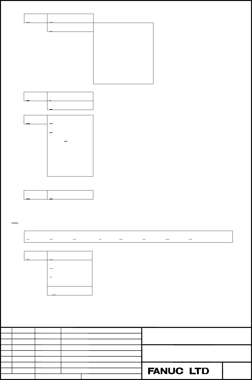
- Page 33Receive Display To select data to be received from CNC File > ( 0) Mainte Info ( 1) All Parameters ( 2) All Program ( 3) One Program ( 4) Operation History ( 5) Alarm History ( 6) Receive Signals Send Input > To select data to be sent to CNC File > Others Setting comm To set up serial port Folder se
- Page 34Edit Copy Operations on Diagnose Data Window Copy to file(I) select Range Find Find Next Mark Jump Select all Erase diag data Phone Phone List Operation for connecting CNC via telephone line Dial Hang comm List Phone history Screen ( 0) POSITION > To switch CNC screens by selecting menu ( 1) PROGRAM
- Page 35Send Input > To select data to be sent to CNC File > Others Setting comm To set up serial port Folder setting To specify folders for file input, output and so on Select Path > Disabled AutoGetScreen > To select whether to forward the screen automatically MDIkey > Disabled Keyfree(Q) To select when t
- Page 364.2 File Menu 4.2.1 Print To print the currently displayed screen on host PC. (Note) Printer setting must be completed on Windows. 4.2.2 US version/Japanese version Switching the message language. 16i/18i/21i The display type and the number of software keys for CNC screen data display is selected at
- Page 374.3 Edit Menu 4.3.1 Copy Selected contents are copied to Windows Clipboard. The equivalent operation can be done by clicking the right button of mouse with the contents selected. 4.3.2 Copy to file (I) Selected contents can be output to a file. Select a file name in File Select Dialog. And the selec
- Page 384.4 Phone Menu 4.4.1 Dial The following window appears. Input the telephone number and press [OK] button. And the connection to telephone line starts. (Note) The type of telephone line must be specified as the item “Tone/Pulse” in the “Setting comm” menu. (Refer to: 4.9.1 Setting Comm) 4.4.2 Hang Se
- Page 394.4.3 Phone list,comm List Easy connection can be done to the targets registered in “comm List”. At first, register the targets to “Phone list” by “comm List” menu. (1) Select “Phone list”. And the following dialog box appears. (2) To register a new target, press “New”. To modify the setting of an a
- Page 40(4) The registered targets’ names are displayed in the “Phone list” part of the “Phone” menu. Easy communication can be done by selecting the “Phone list”. Phone list (Note) Up to 10 names are displayed in the menu out of all registered ones. The order of the names can be sorted by “UP/DOWN” button
- Page 414.4.4 Phone history Communication history can be checked. The “Name” section shows the target name when connecting from the phone list and “Direct Call” when connecting from “Dial” menu. Title FANUC Series 15i/16i/18i/21i Remote Diagnostic Function Host Software (for Windows) Drawing No. A-63555EN 3
- Page 424.5 Screen Menu CNC screens can be switched. Information on the switched CNC screen can be transferred to host PC by “GET SCREEN” button.(Refer to: 4.1.3 Other Buttons) 16i/18i/21i The following screens can be displayed. The items with the signs like “[i]”, [M] and [T] mean that they are available o
- Page 43SYSTEM - PARAMETER - [I] C-OPER - DIAGNOSE - [I] DATA SERVER SETTING - PMC - [I] DATA SERVER MAINTENANCE - SYSTEM - [I] DATA SERVER MODE STORAGE - MEMORY - [I] VGA COLOR SETTING - PITCH ERROR - [I] PERIODICAL MAINTENANCE DISP - SERVO SETTING - [I] MAINTENANCE INFORMATION DISP - SPINDLE SETTING - [I]
- Page 44SERVICE - PARAMETER - SYSTEM CONFIGURATION - PITCH ERROR COMPENSATION - PMC - DIAGNOSIS - SERVO SETTING - DI/DO SIGNAL MONITOR - HPCC - PERIODICAL MAINTENANCE - FSSB SETTING - MAINTENANCE INFORMATION - CONTENTS OF MEMORY MESSAGE - ALARM (Note) In the case that any screen which is not available on th
- Page 454.5.1 Using Screen Switching Function By using the screen menu, soft-keys and/or PAGE UP/DOWN keys on PC screen, connected CNC screens can be switched. The screen on host PC side remains but the information the switched CNC screen can be transferred to the PC by “GET SCREEN” button. The screens on t
- Page 46(Supplementation) After the screen change is operated, screen is automatically got when an AutoGetScreen is turned on. ( “Others(O)” then “AutoGetScree(A)” ) Example of switching screen Last screen display Title FANUC Series 15i/16i/18i/21i Remote Diagnostic Function Host Software (for Windows) Draw
- Page 47Select “Screen”, “(3)SYSTEM” then “(4)SYSTEM” and press GET SCREEN button. And the screen is switched to the following one. Title FANUC Series 15i/16i/18i/21i Remote Diagnostic Function Host Software (for Windows) Drawing No. A-63555EN 3 1999.7.05 Y.Wakinotani 15i is added T.Ohtsuki 2 1999.3.09 N.Ha
- Page 484.6 Receive Menu 4.6.1 Receive (Display) Select “Receive” and then “Display”. And the following data can be displayed . ( 0) CNC Series, Edition (14) Absolute Position (28) Tool Offset(D)2 ( 1) Mainte Info (15) Skip Position (29) Tool Information 1 ( 2) Circuit Info (*1) (16) Servo Error (30) Tool I
- Page 494.6.2 Receive (File) Select “Receive” then “File”. And the following data can be displayed. 16i/18i/21i ( 0) Maintenance Information ( 1) All Parameters ( 2) All Program ( 3) One Program ( 4) Operation History ( 5) Alarm History ( 6) Receive Signals 15i ( 0) Maintenance Information ( 1) All Paramete
- Page 504.7 Send Menu 4.7.1 Send (Input) Select “Send” then “Input”. And the following data can be input. ( 1) Parameter ( 4) Signal ( 2) Offset ( 5) Message ( 3) Macro Variable 4.7.2 Send (File) Select “Send” then “File”. And the following data can be input. ( 1) All Parameters ( 2) Send Program ( 3) Verif
- Page 514.8 Others Menu 4.8.1 Setting Comm The following dialog box appears. Each item is specified as follows. 16i/18i/21i Port : Set serial port number of PC. BPS : Set “9600bps”. DATA Bit : Set “8”. Stop Bit : Set “1”. Parity Bit : Set “None” in the case of using Modem. Flow Control : Set “Xon/Xoff” in t
- Page 52Parity Bit : Set “None”. Flow Control : Set “Xon/Xoff”. Tone/Pulse : Set type of telephone line connected to host PC. Device : Set “Modem” in the case of using Modem. Set “RS-232-C” in the case of direct connection without Modem. Title FANUC Series 15i/16i/18i/21i Remote Diagnostic Function Host Sof
- Page 534.8.2 Folder setting Specify directories for Remote diagnostic software. Each item is as follows. Home directory : Directory where Remote diagnostic software is installed. Upload file directory : Default directory where data is transferred to CNC. Related items : “Send”, “File” Download file directo
- Page 54The following are the ways to modify Folder Setting. a) By key-board (1) Move cursor on the item to be modified by [tab] key. (2) Input data from key-board. b) By mouse (1) Move cursor on the item to be modified by mouse. (2) Press [Browse] button to display Folder select dialog box and select a dir
- Page 554.9 Help Menu 4.9.1 Version information Remote Diagnostic software version is displayed. Example Title FANUC Series 15i/16i/18i/21i Remote Diagnostic Function Host Software (for Windows) Drawing No. A-63555EN 3 1999.7.05 Y.Wakinotani 15i is added T.Ohtsuki 2 1999.3.09 N.Hatanaka Overall revision T.K
- Page 56Appendix A. Applicable Modem Cards The following cards are confirmed to work properly with Remote Diagnostic software. (1) TDK Type Product Name Remarks Modem Card DF2814B for analog line (analog) DF3314ES DF3314EX DF5600 Digital communication DVP3314S for Digital Handy card telephone (2) NTT DOCOMO
- Page 57Appendix B. Description of CNC parameters 16i/18i/21i #7 #6 #5 #4 #3 #2 #1 #0 0201 NCR ASC SB2 [Da t a t ype] Bit #0 SB2 Nu mber of st op bit s 0: 1 bit 1: 2 bit Set “0” in case of Remote Diagnostic function. #1 AS C Da t a ou t pu t code 0: ISO Code 1: ASCII Code Set “1” in case of Remote Diagnosti
- Page 580204 Channel used for remote diagnosis [Da t a t ype] Byt e [Va lid da t a r a n ge] 0, 1, 2 Interface used for remote diagnosis 0, 1 : RS-232-C Serial Port 1 (Channel 1) 2 : RS-232-C Serial Port 2 (Channel 2) 0211 Password 1 for remote diagnose 0212 Password 2 for remote diagnose 0213 Password 3 fo
- Page 590221 Keyword 1 for remote diagnosis 0222 Keyword 2 for remote diagnosis 0223 Keyword 3 for remote diagnosis [Va lid da t a r a n ge] 1 - 99999999 These parameters set the keywords for passwords used with the remote diagnosis function. Keyword 1: Keyword for password 1 (parameter No.211) Keyword 2: K
- Page 6015i #7 #6 #5 #4 #3 #2 #1 #0 0000 RDN EIA NCR ISP [In pu t t ype] Set t in g in pu t [Da t a t ype] Bit #2 ISP Specifies wh et h er ISO codes con t a in a pa r it y bit . 0: Contain parity bit. 1: Do not contain parity bit. A parity bit is located at channel 8 in a punched tape in the ISO code. Set “
- Page 610020 Interface No. of input device for foreground [In pu t t ype] Set t in g in pu t [Da t a t ype] In t eger [Va lid da t a r a n ge] 0 - 16 Assign the interface No. of input device for foreground Set “12” in case of Remote Diagnostic function. 0021 Interface No. of output device for foreground [In
- Page 620042 Password 1 for Remote Diagnostic Function [In pu t t ype] Locked pa r a m et er [Da t a t ype] In t eger [Va lid da t a r a n ge] 0 - 99999999 0043 Keyword 1 for Remote Diagnostic Function [In pu t t ype] Locked pa r a m et er [Da t a t ype] In t eger [Va lid da t a r a n ge] 0 - 99999999 0044
- Page 63Password 1: Sets a password for all services of the remote diagnosis function.(No remote diagnosis function services are available until this password is entered on the host computer (personal computer or other)). Password 2: Sets a password for part programs.(Program-related operations such as prog
- Page 645001 Device number of reader/puncher unit connected to JD5A of MAIN [In pu t t ype] Set t in g in pu t [Da t a t ype] In t eger [Va lid da t a r a n ge] 1-6 Set the device number of the reader/puncher unit connected to connector JD5A. And, set the code numbers of the reader/puncher units correspondi
- Page 655110 Code number of reader/puncher unit corresponding to device number 1 5120 Code number of reader/puncher unit corresponding to device number 2 5130 Code number of reader/puncher unit corresponding to device number 3 5140 Code number of reader/puncher unit corresponding to device number 4 5150 Cod
- Page 665111 Number of stop bits of reader/puncher unit corresponding to device number 1 5121 Number of stop bits of reader/puncher unit corresponding to device number 2 5131 Number of stop bits of reader/puncher unit corresponding to device number 3 5141 Number of stop bits of reader/puncher unit correspon
- Page 675112 Baud rate of reader/puncher unit corresponding to device number 1 5122 Baud rate of reader/puncher unit corresponding to device number 2 5132 Baud rate of reader/puncher unit corresponding to device number 3 5142 Baud rate of reader/puncher unit corresponding to device number 4 5152 Baud rate o