Handy Machine Operator Supplement to Manual Page 53
Supplement to Manual
B-63753EN/01 CONNECTION 2.DETAILS CONNECTION (DETACHABLE CONNECTION)
- 45 -
2.1 TOTAL CONNECTION
TNB(6)
0V
24V
0V
24V
ESPI1
Shield
CA74(2)
CA74(4)
CA74(17)
CA74(12)
Emergency stop button
CA74(11)
Handy machine
operator’s panel
CA74(14)
CA74(13)
CA74(3)
CA74(1)
24V
To CNC and servo
amplifier
Interface unit
Note 1
ESPI1
SOUT
*SOUT
SIN
*SIN
Cabinet
CA74(18)
Enabling switch
ESPI2
EN1
EN2
ESPO1
ESPO2
Lower step
emergency
stop circuit
Upper step
emergency
stop circuit
CA74(19,20)
CA74(10)
24V
External
24VDC
power
supply
24V
0V
ESPI2
EN1
ESPO1
EN2
ESPO21
JD47(5)
JD47(6)
JD47(17)
JD47(19)
JD47(7)
JD47(8)
JD47(10)
JD47(12,14)
SIN
*SIN
SOUT
*SOUT
JD47(1)
JD47(2)
JD47(3)
JD47(4)
TNB(8)
TNB(4)
TNB(7)
TNB(3)
TNB(5)
TNB(2)
TNB(1)
TNB(24V)
TNB(0V)
0V
0V
Connection panel
Detachable
connection switch
Shield
Note 4
NOTE
1 See Note 1) of Section 1.1.
2 The details connection of JD1A, JD1B (I/O Link) of
interface unit is eliminated.
3 The pin connection at the connection panel is
eliminated.
4 To attach a handy machine operator’s panel while
the interface unit, 0V of interface unit must be
connected to 0V of the handy machine operator’s
panel before any other line.
5 When 24 VDC is supplied to the handy machine
operator's panel, the interface unit must be
connected between the power supply and the
operator's panel.
Contents Summary of Handy Machine Operator Supplement to Manual
- Page 1Handy Machine Operator’s Panel CONNECTION MANUAL B-63753EN/01
- Page 2Ȧ No part of this manual may be reproduced in any form. Ȧ All specifications and designs are subject to change without notice. In this manual we have tried as much as possible to describe all the various matters. However, we cannot describe all the matters which must not be done, or which cannot be
- Page 3B-63753EN/01 SAFETY PRECAUTIONS SAFETY PRECAUTIONS This manual includes safety precautions for protecting the user and preventing damage to the machine. Precautions are classified into Warning and Caution according to their bearing on safety. Also, supplementary information is described as a Note. R
- Page 4
- Page 5B-63753EN/01 Table of Contents Table of Contents SAFETY PRECAUTIONS PRECAUTIONS................................ ................................................................ ................................................................................................ ..........................
- Page 6Table of Contents B-63753EN/01 13 SUPPLEMENT ................................................................ ................................................................................................ .............................................................................................
- Page 7B-63753EN/01 Table of Contents 4.2.4 Manual Pulse Generator (MPG) ............................................................................................. 69 4.3 TURNING LED ON/OFF................................................................................................................ 70
- Page 8
- Page 9I. SPECIFICATIO�
- Page 10
- Page 11B-63753EN/01 SPECIFICATION 1.OUTLINE 1 OUTLINE Handy machine operator’s panel is a small size machine operator’s panel for controlling machine tool near machine. Handy machine operator’s panel has a manual pulse generator, a small size LCD, input keys, an emergency stop button and an enabling switch
- Page 122.SPECIFICATION SPECIFICATION B-63753EN/01 2 SPECIFICATION Manual pulse generator Including Display LCD 16 characters × 2 lines Input key 20 (with LED) LED User programmable LED × 2, system LED × 2 FANUC standard key sheet is provided. Key sheet Customization of key sheet is possible with user’s ord
- Page 13B-63753EN/01 SPECIFICATION 3.MAINLY FUNCTIONS 3 MAINLY FUNCTIONS • Input keys, operation ON/OFF switch and override switch on the handy machine operator’s panel are read by PMC ladder program. • The position and messages with figures/alphabet/kana are displayed on the LCD by PMC ladder program. • Th
- Page 144.ENVIRONMENTAL REQUIREMENTSSPECIFICATION B-63753EN/01 4 ENVIRONMENTAL REQUIREMENTS In operation : 0°C to 45°C Room temperature In store or transportation : −20°C to 60°C Relative humidity 30% to 95% (no condensation) In operation : 0.5G or less Vibration In store or transportation : 1.0G or less Pl
- Page 15B-63753EN/01 SPECIFICATION 5.EXTERNAL FIGURE 5 EXTERNAL FIGURE -7-�
- Page 165.EXTERNAL FIGURE SPECIFICATION B-63753EN/01 5.1 HANDY MACHINE OPERATOR’S PANEL Emergency stop button Hole for installation 2 lines×16 characters LCD Single LED Operation ON/OFF switch Override Input key switch with LED ×20 3 positions enabling switch Manual Pulse generator Connector CA74 (Note) Ins
- Page 17B-63753EN/01 SPECIFICATION 5.EXTERNAL FIGURE NOTE For the new handy machine operator's panel which is shipped in around November 2001 and afterward, the height of the manual pulse generator is changed to 96 mm. -9-�
- Page 185.EXTERNAL FIGURE SPECIFICATION B-63753EN/01 5.2 INTERFACE UNIT The outline of interface unit is same as connector panel I/O (A03B- 0815-C001). Connector terminal TNB Fuse FU1 LED LI LD PO MS E0 E1 E2 Installation side Connector to handy machine operator’s panel JD47 I/O Link I/O Link JD1A JD1B Spac
- Page 19B-63753EN/01 SPECIFICATION 6.SYSTEM DIAGRAM 6 SYSTEM DIAGRAM - 11 -�
- Page 206.SYSTEM DIAGRAM SPECIFICATION B-63753EN/01 6.1 IN THE CASE OF KEEPING UNIT ALWAYS Cabinet Emergency input DI CNC FANUC I/O Link To next I/O Link unit 24V Interface unit Emergency Power supply stop circuit Servo Emergency amplifier stop input Handy machine operator’s panel - 12 -
- Page 21B-63753EN/01 SPECIFICATION 6.SYSTEM DIAGRAM 6.2 IN THE CASE OF DETACHABLE CONNECTING Cabinet Emergency input DI CNC FANUC I/O Link To next I/O Link unit 24V Interface unit Emergency Power supply stop circuit Servo Emergency amplifier stop input Connection panel Handy machine operator’s panel - 13 -
- Page 227.EMERGENCY STOP CIRCUIT SPECIFICATION B-63753EN/01 7 EMERGENCY STOP CIRCUIT The emergency stop button and the enabling switch on the handy machine operator’s panel are parts of emergency stop circuit in this system. CNC and servo amplifier must be connected this emergency stop circuit. In the case
- Page 23B-63753EN/01 SPECIFICATION 7.EMERGENCY STOP CIRCUIT NOTE 1 The state of the emergency stop button and the enabling switch on the handy machine operator’s panel can be read by PMC ladder diagram. But emergency stop of CNC is not occurred with this signal on I/O Link. Emergency stop of CNC is occurred
- Page 248.CONNECTION PANEL SPECIFICATION B-63753EN/01 8 CONNECTION PANEL In the case of detachable connection, connection panel is necessary for connection/disconnection to/from cabinet. Connection panel is prepared by MTB. There are connector for connecting the handy machine operator’s panel and detachable
- Page 25B-63753EN/01 SPECIFICATION 8.CONNECTION PANEL 2) Connector for connect/disconnect the handy machine operator’s panel Please use a connector, which has 15 pins or more and doesn’t fall out while operation. Please use connector which the 0V of interface unit is connected to 0V of handy machine operato
- Page 269.CONTROL & CONNECTION/ DISCONNECTION SEQUENCE SPECIFICATION B-63753EN/01 9 CONTROL & CONNECTION/ DISCONNECTION SEQUENCE Starting operation with handy machine operator’s panel Operation ON/OFF switch of handy machine operator’s panel is OFF. 1) The handy machine operator’s panel is connected to the
- Page 27B-63753EN/01 SPECIFICATION 9.CONTROL & CONNECTION/ DISCONNECTION SEQUENCE CAUTION 1 In the case of existing of same purpose switches on the handy machine operator’s panel and main operator’s panel, and the switch is an alternate switch, there are possibility of damage to the machine when this sequen
- Page 2810.CONSTRUCTION PARTS OF HANDY MACHINE OPERATOR’S PANEL SPECIFICATION B-63753EN/01 10 CONSTRUCTION PARTS OF HANDY MACHINE OPERATOR’S PANEL - 20 -
- Page 29B-63753EN/01 SPECIFICATION 10.CONSTRUCTION PARTS OF HANDY MACHINE OPERATOR’S PANEL 10.1 EMERGENCY STOP BUTTON It is available in all operation modes. This switch has push-lock-turn- reset function and the direct opening action function. The state of this button can be read by PMC ladder program. - 2
- Page 3010.CONSTRUCTION PARTS OF HANDY MACHINE OPERATOR’S PANEL SPECIFICATION B-63753EN/01 10.2 ENABLING SWITCH This switch is used for keeping operator’s safety when there is a possibility that the operator using the handy machine operator’s panel exposes him to danger, example the observation working in t
- Page 31B-63753EN/01 SPECIFICATION 10.CONSTRUCTION PARTS OF HANDY MACHINE OPERATOR’S PANEL 10.3 OPERATION ON/OFF SWITCH This is an alternate switch. The state of this switch can be read by PMC ladder program. Please use this switch for the purpose of selecting the operation by handy machine operator’s panel
- Page 3210.CONSTRUCTION PARTS OF HANDY MACHINE OPERATOR’S PANEL SPECIFICATION B-63753EN/01 10.4 LCD The display is 2 lines and 16 characters LCD. The position and the messages with figures/alphabet/kana are displayed by PMC ladder program. - 24 -
- Page 33B-63753EN/01 SPECIFICATION 10.CONSTRUCTION PARTS OF HANDY MACHINE OPERATOR’S PANEL 10.5 INPUT KEY There are 20 input keys. The state of these keys can be read by PMC ladder program. - 25 -
- Page 3410.CONSTRUCTION PARTS OF HANDY MACHINE OPERATOR’S PANEL SPECIFICATION B-63753EN/01 10.6 LED WITH INPUT KEY LEDs are attached with each 20 input keys. These LEDs are turned on/off by PMC ladder program. - 26 -
- Page 35B-63753EN/01 SPECIFICATION 10.CONSTRUCTION PARTS OF HANDY MACHINE OPERATOR’S PANEL 10.7 SINGLE LED There are two LEDs, which is turned on/off by system of handy machine operator’s panel. 1) EN (green); Power on state 2) ALM (red); Watchdog alarm of unit or fusing and attaching alarm of enabling swit
- Page 3610.CONSTRUCTION PARTS OF HANDY MACHINE OPERATOR’S PANEL SPECIFICATION B-63753EN/01 10.8 OVERRIDE SWITCH 16 positions override switch is provided. The divisions of this switch on the case are as follows. → 0,5,10,20,30,40,50,60,70,80,90,95,100,105,110,120% This switch is used for feedrate override in
- Page 37B-63753EN/01 SPECIFICATION 10.CONSTRUCTION PARTS OF HANDY MACHINE OPERATOR’S PANEL 10.9 MANUAL PULSE GENERATOR (MPG) Counter information of MPG is transferred to CNC via FANUC I/O Link after power on the handy machine operator’s panel and turning on the operation ON/OFF switch. (When mode is manual
- Page 3811.FANUC STANDARD KEY SHEET A SPECIFICATION B-63753EN/01 11 FANUC STANDARD KEY SHEET A FANUC standard key sheet A is as follows. This key sheet is put on the standard unit. XYZ 456 SPINDL SPINDL REF START STOP RESET SPINDL SPINDL HANDLE JOG INC DEC ×n F1 FUNC MEM TION MESSAG RAPID SINGLE DRY CYCLE F
- Page 39B-63753EN/01 SPECIFICATION 11.FANUC STANDARD KEY SHEET A • When the “RESET” key is pushed, CNC is reset. Reset and rewind signal should be on for rewinding part program. • Override can be applied to feedrate speed by the override switch on handy machine operator’s panel. Set feedrate override signal
- Page 4011.FANUC STANDARD KEY SHEET A SPECIFICATION B-63753EN/01 3) Jog feed The keys to use are shaded in the following figure. XYZ SPINDL SPINDL REF RESET 456 START STOP SPINDL SPINDL HANDLE JOG + INC DEC FUNC ×n MEM MESSAG RAPID TION SINGLE DRY CYCLE FEED - BLOCK RUN START HOLD • When the “JOG” key is pu
- Page 41B-63753EN/01 SPECIFICATION 11.FANUC STANDARD KEY SHEET A 5) Spindle control The keys to use are shaded in the following figure. XYZ SPINDL SPINDL REF RESET 456 START STOP SPINDL SPINDL HANDLE JOG + INC DEC FUNC ×n MEM MESSAG RAPID TION SINGLE DRY CYCLE FEED - BLOCK RUN START HOLD • When the “SPINDL
- Page 4212.CUSTOMIZATION OF KEY SHEET SPECIFICATION B-63753EN/01 12 CUSTOMIZATION OF KEY SHEET 1) Exclusive key sheet can be designed. The key sheet is put on the unit. Then the unit is shipped. The specification number of the exclusive unit is different from the specification number of standard unit. 2) Cu
- Page 43B-63753EN/01 SPECIFICATION 13.SUPPLEMENT 13 SUPPLEMENT 1) The following edition number or later of control software of CNC is necessary for Handy machine operator’s panel. 16i-TA 18i-TA 21i-TA 16i-MA 18i-MA Edition 01 of Edition 01 of Edition 01 of Edition 02 of Edition 02 of B1F4 BEF4 DEF4 B0F4 02
- Page 44
- Page 45II. CONNECTIO�
- Page 46
- Page 47B-63753EN/01 CONNECTION 1.DETAILS CONNECTION (KEEPING AT ALL TIMES) 1 DETAILS CONNECTION (KEEPING AT ALL TIMES) Cabinet I/O Link upper unit Interface (Optical I/O link adapter) 24VDC Unit JD1A (JD1) Power supply J187 TNB J22 Emergency stop circuit JD1B Handy J22 JD1A machine operator’s panel J186 CA
- Page 481.DETAILS CONNECTION (KEEPING AT ALL TIMES) CONNECTION B-63753EN/01 1.1 TOTAL CONNECTION Cabinet Handy machine operator’s panel Interface unit Emergency stop button 24V CA74(11) ESPI1 ESPI1 JD47(5) TNB(8) Upper step emergency CA74(12) ESPI2 ESPI2 JD47(6) TNB(4) stop circuit CA74(13) EN1 EN1 JD47(17)
- Page 49B-63753EN/01 CONNECTION 1.DETAILS CONNECTION (KEEPING AT ALL TIMES) 1.2 DETAILS OF HANDY MACHINE OPERATOR’S PANEL CABLE J186 Handy machine operator’s panel CA74 Interface unit JD47 (PCR-EV20MDT) 1 2 3 4 1 SIN 11 SIN *SIN SOUT *SOUT 2 *SIN 12 0V 5 6 7 8 9 10 24V J186 3 SOUT 13 11 12 13 14 15 16 4 *SO
- Page 501.DETAILS CONNECTION (KEEPING AT ALL TIMES) CONNECTION B-63753EN/01 The notice of manufacture of cable J186 1) Shield treatment Wire shield is turned up on the rubber of cable. Then put metal fitting on it. So connector main body is connected to shield with this method. 2) Open pins and pins with “(
- Page 51B-63753EN/01 CONNECTION 1.DETAILS CONNECTION (KEEPING AT ALL TIMES) 1.3 DETAILS OF EMERGENCY STOP LINE AND POWER LINE J187 Interface unit TNB 24V Emergency 24V stop circuit 0V 0V 1 ESPO2 2 ESPO2 J187 3 EN2 4 ESPI2 5 ESPO1 PHOENIX contact 24VDC stabilized 6 ESPO1 Co., Ltd. power supply 7 EN1 MSTB2.5/
- Page 522.DETAILS CONNECTION (DETACHABLE CONNECTION) CONNECTION B-63753EN/01 2 DETAILS CONNECTION (DETACHABLE CONNECTION) Cabinet I/O Link upper unit Handy Interface (Optical I/O link adapter) machine 24VDC Unit JD1A (JD1) operator’s Power supply panel CA74 J187 TNB J22 Emergency JD1B stop circuit Connectio
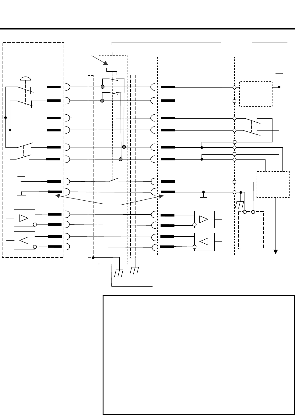
- Page 53B-63753EN/01 CONNECTION 2.DETAILS CONNECTION (DETACHABLE CONNECTION) 2.1 TOTAL CONNECTION Cabinet Handy machine Detachable connection switch Connection panel operator’s panel Emergency stop button Interface unit 24V CA74(11) ESPI1 ESPI1 JD47(5) TNB(8) Upper step emergency CA74(12) ESPI2 ESPI2 JD47(6
- Page 542.DETAILS CONNECTION (DETACHABLE CONNECTION) CONNECTION B-63753EN/01 2.2 DETAILS OF HANDY MACHINE OPERATOR’S PANEL CABLE J188 Handy machine operator’s panel CA74 Connection panel D-SUB 15 pin 1 2 3 4 1 0V 9 24V SIN *SIN SOUT *SOUT 2 ESPI1 10 SIN 5 6 7 8 9 10 3 ESPI2 11 *SIN 24V 4 EN1 12 SOUT J188 11
- Page 55B-63753EN/01 CONNECTION 2.DETAILS CONNECTION (DETACHABLE CONNECTION) 2.3 DETAILS OF HANDY MACHINE OPERATOR’S PANEL CABLE J189 Interface unit JD47 Connection panel (PCR-EV20MDT) D-SUB 15 pin 1 SIN 11 1 0V 9 24V 2 *SIN 12 0V 2 ESPI1 10 SIN 3 SOUT 13 3 ESPI2 11 *SIN 4 *SOUT 14 0V J189 4 EN1 12 SOUT 5 E
- Page 562.DETAILS CONNECTION (DETACHABLE CONNECTION) CONNECTION B-63753EN/01 2.4 THE NOTICE OF MANUFACTURE OF CABLE J188 AND J189 1) Keep the notice of manufacture of cable at Section 1.2. 2) The connector of the connection panel is not always D-sub 15 pin connector. Please use connector that 0V of interfac
- Page 57III. MAINTENANC�
- Page 58
- Page 59B-63753EN/01 MAINTENANCE 1.FUSE 1 FUSE Interface unit has a fuse FU1 for the input of 24VDC power supply. This fuse is for the protection of the input of 24VDC power supply of Handy machine operator’s panel (HMOP) and Interface unit. It has the possibility that the fuse of FU1 blows when the Single
- Page 602.INDICATION OF LED MAINTENANCE B-63753EN/01 2 INDICATION OF LED See the Section 10.7 of the specification material for the Single LED "EN" and "ALM" of HMOP. The following seven LEDs are mounted on Interface unit, and the condition of the unit is indicated. As for the mounting position, see the Sec
- Page 61B-63753EN/01 MAINTENANCE 3.ERROR MESSAGE 3 ERROR MESSAGE Following error message is displayed on LCD of HMOP when error occurs. Message Description Countermeasure The firmware of HMOP SYSTEM ERROR:001 terminated by the Replace HMOP. (CPU WATCHDOG) malfunction SYSTEM ERROR:002 The firmware of HMOP is
- Page 62
- Page 63IV. PMC PROGRAMMIN�
- Page 64
- Page 65B-63753EN/01 PMC PROGRAMMING 1.PREFACE 1 PREFACE Part IV “PMC Programming,” describes the necessary information to perform following operations : - Reading of information of input keys, operation ON/OFF switch and override switch on the handy machine operator’s panel by PMC ladder program. - Display
- Page 662.APPLIED SOFTWARE PMC PROGRAMMING B-63753EN/01 2 APPLIED SOFTWARE The information contained in this document is applicable to the following software. - 58 -�
- Page 67B-63753EN/01 PMC PROGRAMMING 2.APPLIED SOFTWARE 2.1 PMC CONTROL SOFTWARE CNC PMC PMC Series / Edition Series 15i PMC-NB6 404A / 01 or later Series 16i /18i /21i –A PMC-SA5/SB5/SB6 406A / 09 or later Series 21i -A PMC-SA1 406A / 18 or later Series 16i /18i /21i –B PMC-SB7 406G / 01 or later Series 21
- Page 682.APPLIED SOFTWARE PMC PROGRAMMING B-63753EN/01 2.2 OFF-LINE PROGRAMMER Software Specification FAPT LADDER-II A08B-9201-J503 Ladder Editing Package A08B-9201-J510 FAPT LADDER-III (for Windows) A08B-9201-J505 Ladder Editing Package (for Windows) A08B-9201-J511 - 60 -�
- Page 69B-63753EN/01 PMC PROGRAMMING 3.PREPARATIONS FOR USING 3 PREPARATIONS FOR USING - 61 -�
- Page 703.PREPARATIONS FOR USING PMC PROGRAMMING B-63753EN/01 3.1 ASSIGNMENT OF ADDRESS Assignment of I/O Link address is needed for LADDER program because the handy machine operator’s panel is connected to CNC by I/O link. Handy machine operator's panel uses continuous 16 bytes for X and continuous 32 byte
- Page 71B-63753EN/01 PMC PROGRAMMING 3.PREPARATIONS FOR USING 3.2 DI/DO MAP ON I/O Link Assigned address is used as follows. X Bits 0 to 7 Y Bits 0 to 7 +0 +0 +1 Power-on/off +1 LED bit image +2 information +2 +3 +3 +4 +4 LCD line control Status of Handy +5 +5 1st (left) character of selected machine operat
- Page 724.OUTLINE OF HANDY MACHINE OPERATOR'S PANEL FUNCTIONS PMC PROGRAMMING B-63753EN/01 4 OUTLINE OF HANDY MACHINE OPERATOR'S PANEL FUNCTIONS Function that can be executed by PMC LADDER program is described. - 64 -�
- Page 73B-63753EN/01 PMC PROGRAMMING4.OUTLINE OF HANDY MACHINE OPERATOR'S PANEL FUNCTIONS 4.1 COMMUNICATION ERROR AND POWER-ON/OFF INFORMATION Address Bit 7 Bit 6 Bit 5 Bit 4 Bit 3 Bit 2 Bit 1 Bit 0 X+0 PWR08 PWR07 PWR06 PWR05 PWR04 PWR03 PWR02 PWR01 X+1 PWR16 PWR15 PWR14 PWR13 PWR12 PWR11 PWR10 PWR09 X+2 -
- Page 744.OUTLINE OF HANDY MACHINE OPERATOR'S PANEL FUNCTIONS PMC PROGRAMMING B-63753EN/01 4.2 OPERATING INFORMATION OF HANDY MACHINE OPERATOR'S PANEL State of override switch, emergency stop button, operation on/off switch, 3 position enabling switch, input keys and manual pulse generator can be read. The
- Page 75B-63753EN/01 PMC PROGRAMMING4.OUTLINE OF HANDY MACHINE OPERATOR'S PANEL FUNCTIONS NOTE 1 Please check OVREN (Valid override switch signal) is "1" before referring to OVR0 -OVR3. When the HMOP is disconnected or the power is off or communication alarm is occurred, the above signals will be “0”. It ca
- Page 764.OUTLINE OF HANDY MACHINE OPERATOR'S PANEL FUNCTIONS PMC PROGRAMMING B-63753EN/01 4.2.2 Emergency Stop Button, 3 Position Enabling Switch, Operation On/Off Switch ON/OFF state of Operation on/off switch can be read. So, it can be decided that the signals from the HMOP can be used. And the states of
- Page 77B-63753EN/01 PMC PROGRAMMING4.OUTLINE OF HANDY MACHINE OPERATOR'S PANEL FUNCTIONS 4.2.3 Input Keys By using these input signals, state of 20 input keys can be read. When the HMOP is disconnected or the power is off or communication alarm is occurred, the signals will be all “0”. Address Bit7 Bit 6 B
- Page 784.OUTLINE OF HANDY MACHINE OPERATOR'S PANEL FUNCTIONS PMC PROGRAMMING B-63753EN/01 4.3 TURNING LED ON/OFF By using these output signals, PMC LADDER can control LED. To turn an LED on/off, turn on/off an output signal corresponds to the LED. Address Bit7 Bit 6 Bit 5 Bit 4 Bit 3 Bit 2 Bit 1 Bit 0 Y+0
- Page 79B-63753EN/01 PMC PROGRAMMING4.OUTLINE OF HANDY MACHINE OPERATOR'S PANEL FUNCTIONS 4.4 CHARACTER DISPLAY ON LCD 2 lines of 16 characters data can be displayed on LCD by PMC ladder program. Not only fixed strings data but also a data containing a binary data can be displayed. (Numeric variable display
- Page 804.OUTLINE OF HANDY MACHINE OPERATOR'S PANEL FUNCTIONS PMC PROGRAMMING B-63753EN/01 4.4.1 LCD Display Control 1 These are input signals from HMOP for using LCD display control. Address Bit 7 Bit 6 Bit 5 Bit 4 Bit 3 Bit 2 Bit 1 Bit 0 X+6 (Reserved) (Reserved) (Reserved) (Reserved) LCDER2 LCDER1 LCDER0
- Page 81B-63753EN/01 PMC PROGRAMMING4.OUTLINE OF HANDY MACHINE OPERATOR'S PANEL FUNCTIONS 4.4.2 LCD Display Control 2 These are output signals to HMOP for using LCD display control. Address Bit 7 Bit 6 Bit 5 Bit 4 Bit 3 Bit 2 Bit 1 Bit 0 Y+4 (Reserved) (Reserved) (Reserved) (Reserved) (Reserved) (Reserved)
- Page 824.OUTLINE OF HANDY MACHINE OPERATOR'S PANEL FUNCTIONS PMC PROGRAMMING B-63753EN/01 • The location where numeric variable code (16) was specified is substituted for the character strings which displays numeric variable (X+21 to X+31). When the numeric variable is shown by two or more digits, the char
- Page 83B-63753EN/01 PMC PROGRAMMING4.OUTLINE OF HANDY MACHINE OPERATOR'S PANEL FUNCTIONS 4.4.4 Numeric Variable Format Specification1 (Data Type, Data Length) These are output signals to specify the type and length of numeric variable data. Address Bit 7 Bit 6 Bit 5 Bit 4 Bit 3 Bit 2 Bit 1 Bit 0 Y+21 VDTLN
- Page 844.OUTLINE OF HANDY MACHINE OPERATOR'S PANEL FUNCTIONS PMC PROGRAMMING B-63753EN/01 Bits 4 to 7: Length (bytes) of numeric variable data Bit 7 Bit 6 Bit 5 Bit 4 Description VDTLN3 VDTLN2 VDTLN1 VDTLN0 0 The numeric variable is not used. 0 1 Length of numeric variable data is 1 byte. 0 0 Length of num
- Page 85B-63753EN/01 PMC PROGRAMMING4.OUTLINE OF HANDY MACHINE OPERATOR'S PANEL FUNCTIONS 4.4.5 Numeric Variable Format Specification 2 (Decimals) These are output signals to specify the digits, accuracy and display position of decimals of numeric variable data. Address Bit 7 Bit 6 Bit 5 Bit 4 Bit 3 Bit 2 B
- Page 864.OUTLINE OF HANDY MACHINE OPERATOR'S PANEL FUNCTIONS PMC PROGRAMMING B-63753EN/01 • Rounding are done according to this setting when effective number of digits below the decimal point of numeric variable is larger than the number of digits specified with DSPDE0-2 (Number of display columns below de
- Page 87B-63753EN/01 PMC PROGRAMMING4.OUTLINE OF HANDY MACHINE OPERATOR'S PANEL FUNCTIONS 4.4.6 Numeric Variable Format Specification 3 (Number of Display Columns) These are output signals to specify the number of display columns of whole data and decimals. Address Bit 7 Bit 6 Bit 5 Bit 4 Bit 3 Bit 2 Bit 1
- Page 884.OUTLINE OF HANDY MACHINE OPERATOR'S PANEL FUNCTIONS PMC PROGRAMMING B-63753EN/01 4.4.7 Numeric Variable Data These are output signals to specify numeric variable data. Address Bit 7 Bit 6 Bit 5 Bit 4 Bit 3 Bit 2 Bit 1 Bit 0 Y+24 VDATA0: The first byte of the numeric variable data Y+25 VDATA1: The
- Page 89B-63753EN/01 PMC PROGRAMMING4.OUTLINE OF HANDY MACHINE OPERATOR'S PANEL FUNCTIONS 4.4.8 LCD Character-Code Table *1) Numeric bariable code *2) Transparent code *3) Minus *4) Under bar - 81 -�
- Page 905.DI/DO INFORMATION TABLE PMC PROGRAMMING B-63753EN/01 5 DI/DO INFORMATION TABLE - 82 -�
- Page 91B-63753EN/01 PMC PROGRAMMING 5.DI/DO INFORMATION TABLE 5.1 INPUT SIGNALS address Bit 7 Bit 6 Bit 5 Bit 4 Bit 3 Bit 2 Bit 1 Bit 0 X+0 PWR08 PWR07 PWR06 PWR05 PWR04 PWR03 PWR02 PWR01 X+1 PWR16 PWR15 PWR14 PWR13 PWR12 PWR11 PWR10 PWR09 X+2 - - PWR22 PWR21 PWR20 PWR19 PWR18 PWR17 X+3 ERINF - - - - - - -
- Page 925.DI/DO INFORMATION TABLE PMC PROGRAMMING B-63753EN/01 5.2 OUTPUT SIGNALS address Bit 7 Bit 6 Bit 5 Bit 4 Bit 3 Bit 2 Bit 1 Bit 0 Y+0 LED2 LED1 - LED15 LED14 LED13 LED12 LED11 Y+1 - - - LED25 LED24 LED23 LED22 LED21 Y+2 - - - LED35 LED34 LED33 LED32 LED31 Y+3 - - - LED45 LED44 LED43 LED42 LED41 Y+4
- Page 93B-63753EN/01 PMC PROGRAMMING 6.EXAMPLE OF LADDER DIAGRAM 6 EXAMPLE OF LADDER DIAGRAM - 85 -�
- Page 946.EXAMPLE OF LADDER DIAGRAM PMC PROGRAMMING B-63753EN/01 6.1 EMERGENCY STOP USING ENABLE SWITCH ON HMOP Judgement of various emergency conditions according to operation on/off switch, emergency stop button and 3 position enable switch on HMOP. Fig.6.1 Emergency stop - 86 -�
- Page 95B-63753EN/01 PMC PROGRAMMING 6.EXAMPLE OF LADDER DIAGRAM 6.2 CHANGING CNC MODE BY HANDLE KEY Changing CNC mode to HANDLE and LED besides HANDLE key turned on when HANDLE key is pushed. Detect turning on of key signal to execute following procedure once when key is pushed. Set CNC mode signal. Turn o
- Page 966.EXAMPLE OF LADDER DIAGRAM PMC PROGRAMMING B-63753EN/01 6.3 SETTING OF JOG OVERRIDE Pick up OVR0 – OVR3 from the Status of HMOP signal when OVREN is 1. Get override value from table and set to *JV0 - *JV15 according to override switch position. This is an error handling procedure for above XMOVB. F
- Page 97B-63753EN/01 PMC PROGRAMMING 6.EXAMPLE OF LADDER DIAGRAM Override value (complement value of % unit) must be prepared previously to R100 – R132. And, data number of table(=16) must be set to R98 too. Address R98 R100 R102 R104 R106 R108 R110 R112 R114 Contents (decimal) 16 -1 -501 -1001 -2001 -3001
- Page 986.EXAMPLE OF LADDER DIAGRAM PMC PROGRAMMING B-63753EN/01 6.4 SETTING OF MANUAL HANDLE FEED AMOUNT SELECTION SIGNAL BY XN KEY Detect turning on of Xn key signal. Counts up by using CTR instruction. (C6 must be set 4 beforehand) Copy content of counter value to MP1 and MP2 when Xn key is pushed or res
- Page 99B-63753EN/01 PMC PROGRAMMING 6.EXAMPLE OF LADDER DIAGRAM 6.5 SELECTION OF AXIS BY XYZ456 KEY Set 1 to HANDLEAXIS_TMP when it is 0. It is the procedure when power turned on. Shift HANDLEAXIS_TMP to left when XYZ456 key is pushed. - 91 -�
- Page 1006.EXAMPLE OF LADDER DIAGRAM PMC PROGRAMMING B-63753EN/01 Set 1 to HANDLEAXIS_TMP when it is over the axis number. Axis number is 3 in this sample 3 LADDER.(8 is equal to 2 ) Copy HANDLEAXIS_TMP to HS1A-HS1D when FUNCTION key is pushed. Fig.6.5 Selection axis - 92 -�
- Page 101B-63753EN/01 PMC PROGRAMMING 6.EXAMPLE OF LADDER DIAGRAM 6.6 INFORMATION DISPLAY TO LCD Fig. 6.6.1 shows the strings on LCD. The most left character of second line shows the selected axis by XYZ456 key, and ???% shows the JOG override value. column 1 2 3 4 5 6 7 8 9 10 11 12 13 14 15 16 LCD upper li
- Page 1026.EXAMPLE OF LADDER DIAGRAM PMC PROGRAMMING B-63753EN/01 Set No decimal digits, right justified and stuff space character to Variable format 2. Set 3 to the number of display column of Variable format 3. Complement the value of JOG override for LCD display. - 94 -�
- Page 103B-63753EN/01 PMC PROGRAMMING 6.EXAMPLE OF LADDER DIAGRAM Divide the complement JOG override value by 100 (to convert 0.01% unit to 1% unit) and set to numeric variable data area. Following from here is a sequence for LCD display. If immediately after the LCD display, wk=1. Besides, wk=0. If immediat
- Page 1046.EXAMPLE OF LADDER DIAGRAM PMC PROGRAMMING B-63753EN/01 • About display character data of the first line. LCD display character data of the following content is stored in R0300-R0315 beforehand. See Fig.6.3(b) for the sequence. Character- Transferring displayed Destination Address code by MOVN at c
- Page 105B-63753EN/01 PMC PROGRAMMING 6.EXAMPLE OF LADDER DIAGRAM • About variable data of the 2nd line Sequence of displaying JOG override value is included in Fig. 6.6(b). Getting the selected axis name to display is done in the procedure of axis selection which is executed when XYZ456 key is pushed. That
- Page 106
- Page 107APPENDI�
- Page 108
- Page 109B-63753EN/01 APPENDIX A.CONNECTING A MANUAL PULSE GENERATOR FOR 16i/18i/21i-A/B, AND Power Mate i A CONNECTING A MANUAL PULSE GENERATOR FOR 16i/18i/21i-A/B, AND Power Mate i When connecting a manual pulse generator to I/O Link, use a module that can be connected to the manual pulse generator (connec
- Page 110A.CONNECTING A MANUAL PULSE GENERATOR FOR 16i/18i/21i-A/B, AND Power Mate i APPENDIX B-63753EN/01 In the example illustrated above, the manual pulse generators connected to groups #0, #1, and #2 are enabled, and the manual pulse generator connected to the handy machine operator's panel of group #3 c
- Page 111B-63753EN/01 APPENDIX B.CONNECTING THE SECOND CHANNEL OF I/O Link FOR Series 16i/18i/21i-A/B B CONNECTING THE SECOND CHANNEL OF I/O Link FOR Series 16i/18i/21i-A/B No handy machine operator's panel can be connected to the second channel of I/O Link of the Series 16i/18i/21i. (The Series 15i and Powe
- Page 112
- Page 113B-63753EN/01 Index Index A E APPLIED SOFTWARE .................................... 58 EMERGENCY STOP BUTTON....................... 21 ASSIGNMENT OF ADDRESS ........................ 62 Emergency Stop Button, 3 Position Enabling Switch, Operation On/Off Switch................. 68 C EMERGENCY STOP CIRC
- Page 114Index B-63753EN/01 LED WITH INPUT KEY .................................. 26 OVERRIDE SWITCH ....................................... 28 M P MAINLY FUNCTIONS ...................................... 5 PMC CONTROL SOFTWARE ......................... 59 MANUAL PULSE GENERATOR (MPG)........ 29 PREPARATIONS
- Page 115Revision Record Handy Machine Operator’s Panel CONNECTION MANUAL (B-63753EN) 01 Nov., 2001 Edition Date Contents Edition Date Contents
- Page 116