Dual Check Safety Operators manual Page 97
Operators manual
B-64004EN/02 6.PARAMETERS
- 89 -
(The bit positions A, B, C and D vary, depending on the type of
signal.)
[Example of setting]
Spindle number No.3022 Signal allocation
1 0 TLMLA<G0070.0>, TLMHA<G0070.1>,
ALMA<F0045.0>, ...
2 1 TLMLB<G0074.0>, TLMHB<G0074.1>,
ALMB<F0049.0>, ...
3 10 TLMLA<G1070.0>, TLMHA<G1070.1>,
ALMA<F1045.0>, ...
4 11 TLMLB<G1074.0>, TLMHB<G1074.1>,
ALMB<F1049.0>, ...
If four or less axes are used per path, the following signal allocation
results when 0 is set for all axes:
Axis 1 of path 1 = Setting equivalent to 0
Axis 2 of path 1 = Setting equivalent to 1
:
Axis 1 of path 2 = Setting equivalent to 10
NOTE
Set this parameter when more than four axes are
used per path.
The valid data range varies, depending on the
system software.
3225 Code for safety parameters
NOTE
When this parameter is set, the power must be
turned off before operation is continued.
[Input type] Parameter input
[Data type] 2-word
[Valid data range] 0 to 99999999
Set a code (password) for protecting against modifications to
parameters related to Dual Check Safety function (safety parameters).
When a code for safety parameters is set other than the value “0”, the
parameters are locked. In this state, the setting (code) is not displayed
but is blank, and safety parameter input is disabled.
If an attempt is made to input data in a locked safety parameter, the
result indicated in the table below is produced, depending on the
method of input. No attempt is successful.
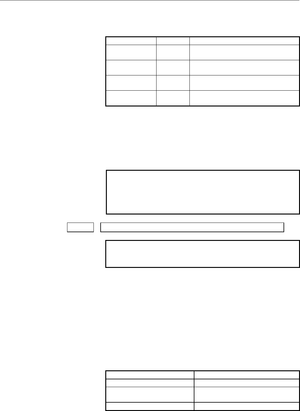
Input method Result
MDI input Warning “WRITE PROTECT”
Input via reader/puncher interface No alarm is generated. But parameter
input is disabled.
Input through window function Completion code 7 (WRITE PROTECT)
If the value other than “0” is set to this parameter, the safety parameter
cannot be modified. The safety parameters can be set when the safety
Contents Summary of Dual Check Safety Operators manual
- Page 1FANUC Series 30*/300*/300*s-MODEL A FANUC Series 31*/310*/310*s-MODEL A5 FANUC Series 31*/310*/310*s-MODEL A FANUC Series 32*/320*/320*s-MODEL A Dual Check Safety OPERATOR’S MANUAL B-64004EN/02
- Page 2• No part of this manual may be reproduced in any form. • All specifications and designs are subject to change without notice. The export of this product is subject to the authorization of the government of the country from where the product is exported. In this manual we have tried as much as possi
- Page 3B-64004EN/02 DEFINITION OF WARNING, CAUTION, AND NOTE DEFINITION OF WARNING, CAUTION, AND NOTE This manual includes safety precautions for protecting the user and preventing damage to the machine. Precautions are classified into Warning and Caution according to their bearing on safety. Also, supplem
- Page 4
- Page 5B-64004EN/02 TABLE OF CONTENTS TABLE OF CONTENTS DEFINITION OF WARNING, CAUTION, AND NOTE .................................s-1 1 OVERVIEW ............................................................................................. 1 1.1 DIRECTIVE AND STANDARDS ......................................
- Page 6TABLE OF CONTENTS B-64004EN/02 3.11 PARAMETER LOCK FUNCTION ................................................................ 37 3.12 SEFETY POSITION ERROR MONITORING FUNCTION ........................... 38 3.13 AMPLIFIER CIRCUIT MONITORING FUNCTION....................................... 39 3.14 SAFE
- Page 7B-64004EN/02 TABLE OF CONTENTS 9.3 FLOW MONITORING SCREEN ................................................................ 128 9.4 FEED LIMIT MONITORING SCREEN....................................................... 129 9.5 SAFE MACHINE POSITIONING MONITORING SCREEN ....................... 131 9.6 SA
- Page 8
- Page 9B-64004EN/02 1.OVERVIEW 1 OVERVIEW Setup for machining, which includes attaching and detaching a workpiece to be machined, and moving it to the machining start point while viewing it, is performed with the protection door opened. The dual check safety function provides a means for ensuring a high le
- Page 101.OVERVIEW B-64004EN/02 IMPORTANT The dual check safety function cannot monitor the stop state of the motors. -2-
- Page 11B-64004EN/02 1.OVERVIEW 1.1 DIRECTIVE AND STANDARDS 1.1.1 Directives Machine tools and their components must satisfy the EC directives listed below. The FANUC CNC systems with the dual check safety function are compatible with all of these directives. Directive Directive 98/37/EC 1998 Safety of mach
- Page 121.OVERVIEW B-64004EN/02 1.2 DEFINITION OF TERMS 1.2.1 General Definition of Terms Reliability and safety Reliability and safety are defined by EN292-1 as follows: Term Definition Reliability Capability of a machine, machine component, or equipment to perform its required function under a specified c
- Page 13B-64004EN/02 1.OVERVIEW 1.3 BASIC PRINCIPLE OF DUAL CHECK SAFETY 1.3.1 Features of Dual Check Safety Dual Check Safety function has the following features. - Two-channel configuration with two or more independent CPUs - Cross-check function for detecting latent errors Detection A servo motor detecto
- Page 141.OVERVIEW B-64004EN/02 CNC Shut off power CPU Motor detector Cross-check Magnetic signal of data and results contactor 電磁接触器 Servo PMC Spindle Shut off power CPU CPU Door switch signal Monitoring of servo motor and spindle motor movement Data output from the detector built into each motor is transf
- Page 15B-64004EN/02 1.OVERVIEW 1.3.2.1 Latent error detection and cross-check Detection of latent errors This detection function can detect latent software and hardware errors in a system that has a two-channel configuration. So, the safety-related portions of the two channels need to be tested at least on
- Page 161.OVERVIEW B-64004EN/02 1.3.2.3 Error analysis Error analysis The table below indicates the results of system error analysis controlled by the dual check safety function. Error analysis when the protection door is open Error Cause Action Excessive speed Amplifier or control unit failure, Safety limi
- Page 17B-64004EN/02 1.OVERVIEW e) The simultaneous failure of two power transistors in the inverter may cause the axis to briefly (motion depend on number of pole pairs of motor) Example: An 8-pole synchronous motor can cause the axis to move by a maximum of 45 degrees. With a lead-screw that is directly d
- Page 181.OVERVIEW B-64004EN/02 1.4 GENERAL INFORMATION The following requirements must be fulfilled for the Dual-Check System: - All conditions of the certification report have to be respected. - The procedures for the changes in the System (either HW or SW) should be referred to maintenance manual (B-6394
- Page 19B-64004EN/02 1.OVERVIEW [ CNC SE INTERFACE COURSE ] Training course offered to the engineers who design CNC machine tools or CNC application system for the first time. This course is also suitable for customers who provide to retrofitting, to develop an original CNC machine tools or new application
- Page 202.SYSTEM CONFIGURATION B-64004EN/02 2 SYSTEM CONFIGURATION The dual check safety function has the following components. Applicable CNC FANUC Series 30i/300is/300i FANUC Series 31i/310is/310i A5 FANUC Series 31i/310is/310i FANUC Series 32i/320is/320i Number of controlled axes - Series 30i/300is/300i
- Page 21B-64004EN/02 2.SYSTEM CONFIGURATION Software - Dual check safety software option DETECTOR SYSTEM The detectors below can be used. Feed axis detector -Pulsecoder αA1000, αA64, - αA16000i, αA1000i, αI1000i, αA64i - βA64B, βA32B - βI64B, βI32B - Separate type detector (A quard B) Spindle detector - M s
- Page 223.SAFETY FUNCTIONS B-64004EN/02 3 SAFETY FUNCTIONS - 14 -
- Page 23B-64004EN/02 3.SAFETY FUNCTIONS 3.1 APPLICATION RANGE The dual check safety function assumes the following configuration: A) At least, one protective door is provided. B) If protective door is closed, safety is assured. When the operator makes a request to open the protective door, the safety functi
- Page 243.SAFETY FUNCTIONS B-64004EN/02 CAUTION This safety function is enabled while the protective door is open after a request to open the protective door is made. If the request to open the protective door is canceled and if the protective door is closed, this safety function is disabled. The dual input
- Page 25B-64004EN/02 3.SAFETY FUNCTIONS 3.2 BEFORE USING THE SAFETY FUNCTION 3.2.1 Important Items to Check Before Using the Safety Function When using the safety function for the first time upon assembly of the machine, replacing a part, or changing a safety parameter (such as a safe speed limit or safe ra
- Page 263.SAFETY FUNCTIONS B-64004EN/02 3.3 STOP 3.3.1 Stopping the Spindle Motor Because the spindle motor is an induction type motor, power-down during rotation causes the motor to continue rotating for a certain amount of time. From a safety standpoint, the motor may have to be stopped immediately. If an
- Page 27B-64004EN/02 3.SAFETY FUNCTIONS If the input of the Emergency Stop signal or an error of a safe-related signal or speed monitoring is detected, the CNC automatically specifies a command to zero the speed and reduces the speed to zero (controlled stop). After the motor slows down and stops, the power
- Page 283.SAFETY FUNCTIONS B-64004EN/02 3.4 SAFE-RELATED I/O SIGNAL MONITORING A set of safe-related I/O signals are connected to the two channels of the I/O respectively. As for safe-related I/O signals, a pair of signals are prepared and connected to each I/O through different paths. The two independent C
- Page 29B-64004EN/02 3.SAFETY FUNCTIONS This section briefly describes the signals. For details, see Chapter 5, “OPERATION.” For specific connections, see the sample system configuration in Chapter 10. NOTE 1 Dual Check Safety PMC (DCS PMC) 2 First path PMC, Second path PMC, Third path PMC Please refer to “
- Page 303.SAFETY FUNCTIONS B-64004EN/02 I/O related with Dual Check Safety Function PMC(n=path(0-9)) DCS PMC (m=path(0-9) x20) Symbol Signal name I/O address 1 *ESP Emergency Stop signal
- Page 31B-64004EN/02 3.SAFETY FUNCTIONS 2. *SGOPN Guard State signal (Machine side input signal) The signal is provided for double monitoring of the protective door state. The signal is connected so that it is normally set to 1 while the protective door is closed and locked (door closed) and set to 0 otherw
- Page 323.SAFETY FUNCTIONS B-64004EN/02 8. SPS1 to SPS32 (SPS33 to SPS64 in case of 2 or more path) Safety Position Switch (output) These signals show whether the machine position of each axis is stayed within the range specified by the parameters or not. 9. Programmable Safety I/O signals (input/output) Th
- Page 33B-64004EN/02 3.SAFETY FUNCTIONS must provide an output signal that opens the actual protective door through the PMC. 11. OPT Test Mode signal (input) When the signal is input, a MCC off Test is executed. The MCC off Test checks whether the contact of the MCC is abnormally closed. When carrying out t
- Page 343.SAFETY FUNCTIONS B-64004EN/02 Guard Open Request signal and Guard Unlock signal CNC(PMC) Door open request 24V X G Protective door Ladder ORQ ORQ-I Y *OPIHB F Ladder Protective RSVx F door lock RSPx F POSEx The figure shows a sample connection of the protective door open request switch and the gua
- Page 35B-64004EN/02 3.SAFETY FUNCTIONS IMPORTANT The PMC ladder must be designed to monitor whether the protective door is open (*SGOPN is set to 0) while ORQ is set to 0. If the door open is detected, the PMC ladder judges that an abnormal event has occurred and enters the safe stop state. This can occur,
- Page 363.SAFETY FUNCTIONS B-64004EN/02 CAUTION Ensure a time of 100 ms or longer (“t” in the figure) from when the door is closed (locked) until the Guard Open Request signal (ORQ) goes off. If this time requirement is not satisfied, an alarm may be raised when the door is closed (locked). Design an operat
- Page 37B-64004EN/02 3.SAFETY FUNCTIONS 3.5 EMERGENCY STOP The Emergency Stop signal is monitored in redundant mode. When the emergency stop is input, the servo motor slows down to a stop (*see the below caution) and enters the dynamic brake stop. The spindle slows down to a stop (*see the below caution) as
- Page 383.SAFETY FUNCTIONS B-64004EN/02 3.6 SAFE SPEED MONITORING If the safe speed range is exceeded while the protective door is open, the dual check safety function immediately enters the stop state. If each axis or spindle is not stopped, the dual check safety function enters the safety stop state. For
- Page 39B-64004EN/02 3.SAFETY FUNCTIONS IMPORTANT 1 A gear ratio, ball screw, and the like must be carefully selected so that a safe speed can be kept on the feed axis. 2 Before inputting the Guard Open Request signal (ORQ), reduce each axial speed and spindle speed to a safe speed range or below. If a spee
- Page 403.SAFETY FUNCTIONS B-64004EN/02 3.7 SAFE MACHINE POSITION MONITORING While the door is open, the dual check safety function checks whether the position on each feed axis is within the safe machine position range defined by safety parameters. If it detects a machine position beyond the safety range,
- Page 41B-64004EN/02 3.SAFETY FUNCTIONS The user of the machine must first carry out a reference position return in order to obtain the initial position. If the reference position return is not carried out, the check function is disabled. This check function is enabled after the reference position is establ
- Page 423.SAFETY FUNCTIONS B-64004EN/02 3.8 MCC OFF TEST A MCC off Test must be carried out in intervals of 24 hours, so that the safety functions would not be damaged by a possible cause of failure. A message telling that the MCC off Test must be carried out is displayed at power-on or when 24 hours have e
- Page 43B-64004EN/02 3.SAFETY FUNCTIONS 3.9 SAFETY POSITION SWITCH FUNCTION It is checked whether the machine position is within the range of safety position switch. The checked result is outputted to the Safety Position Switch signal. The correspondence between axes and each signal is specified by the para
- Page 443.SAFETY FUNCTIONS B-64004EN/02 NOTE The machine coordinate of the safety function is based on position feed back. So it does not always indicate the same value as the machine coordinate based on the summation of the command value. Two machine coordinates that are calculated by two CPU independently
- Page 45B-64004EN/02 3.SAFETY FUNCTIONS 3.10 SAFETY RELATED PARAMETERS CHECK FUNCTION At every power-on, the CNC checks whether the safety related parameters are destroyed and are transferred to the SV, the SP and the PMC normally or not. The SV, the SP and the PMC also check whether the safety related para
- Page 463.SAFETY FUNCTIONS B-64004EN/02 3.12 SEFETY POSITION ERROR MONITORING FUNCTION Both the CNC and the SV check whether the servo following error of each axis exceeds the limit of deviation specified by the parameters. If the servo following error exceeds, an alarm is generated and MCC OFF signal (*MCF
- Page 47B-64004EN/02 3.SAFETY FUNCTIONS 3.13 AMPLIFIER CIRCUIT MONITORING FUNCTION The SV and the SP transmit the data of plural axes to amplifiers through one electronic circuit (LSI). The CNC, the SV and the SP check whether this transmission is performed normally without placing data on wrong address. In
- Page 483.SAFETY FUNCTIONS B-64004EN/02 3.14 SAFETY BRAKE SIGNAL OUTPUT FUNCTION The CNC and the SV output the Safety Brake signal (*BRKx) to control the mechanical brake. When this signal is “0”, mechanical brake must be activated. When this signal is “1”, mechanical brake is allowed to be released. These
- Page 49B-64004EN/02 3.SAFETY FUNCTIONS 3.15 CPU SELF TEST FUNCTION The CNC, the PMC, the SV and the SP carry out the following self-diagnosis. If the error is detected, the alarm is generated and sets MCC Off signal (*DCALM) to “0”. <1> CPU check It is checked whether each CPU runs normally or not. It is c
- Page 503.SAFETY FUNCTIONS B-64004EN/02 3.16 RAM CHECK FUNCTION ECC (Error Check and Correct) function is applied to the battery back-upped file memory. Then a single-bit error is corrected. And, when an error that cannot be corrected occurs, memory parity error is generated. Other memory for dual check saf
- Page 51B-64004EN/02 3.SAFETY FUNCTIONS 3.18 SAFE STOP MONITORING When a safety door is open, safe stop monitoring for servo axis and spindle can be realized by the combination of several functions. Safe stop monitoring for servo axis According to the safe speed monitoring for servo axis and the safe positi
- Page 524.INSTALLATION B-64004EN/02 4 INSTALLATION The hardware installation such as field wiring, power supply, etc. should be referred to connection manual for CNC units and for servo amplifier. EMC problem should be referred to EMC guideline manual. Degree of IP protection: Servo Motors: IP55 Spindle Mot
- Page 53B-64004EN/02 4.INSTALLATION 4.1 OVERALL CONNECTION DIAGRAM In case of using the 2 channel I/O link CNC Main board 3ch I/O Link branching I/O-LINK(JD51A) adapter JD51B I/O LINK #1/#2 JD44A-1 (general I/O, safety-related I/O) JD44A-2 JD1A Manual pulse Distribution-type generator I/O board 24VDC CPD1 J
- Page 544.INSTALLATION B-64004EN/02 In case of using the 1 channel I/O link and Profi-bus I/O CNC Main board I/O-LINK(JD51A) I/O LINK#1#2 (general I/O, safety-related I/O for PMC) Profi-bus board Profi-bus Manual pulse (CN1) Distribution-type generator I/O board 24VDC CPD1 JA3 Operator’s JD1B panel JD1A I/O
- Page 55B-64004EN/02 5.I/O SIGNALS 5 I/O SIGNALS - 47 -
- Page 565.I/O SIGNALS B-64004EN/02 5.1 OVERVIEW The Dual Check Safety Function provides two input paths and two output paths for safe-related signals (safety signals). For input signals (safety input signals), two paths are used: one path for input to the CNC via I/O Link#3,#4 or Profibus-DP (Note1), and an
- Page 57B-64004EN/02 5.I/O SIGNALS 5.2 SIGNAL ADDRESS Via I/O Link#1/#2 PMC (n=0 to 9 (Path number-1)) #7 #6 #5 #4 #3 #2 #1 #0 X008 *ESP *ESP *ESP #7 #6 #5 #4 #3 #2 #1 #0 Gn008 *ESP #7 #6 #5 #4 #3 #2 #1 #0 Gn191 ORQ OPT #7 #6 #5 #4 #3 #2 #1 #0 Gn748 *SMC #7 #6 #5 #4 #3 #2 #1 #0 Gn749 #7 #6 #5 #4 #3 #2 #1 #0
- Page 585.I/O SIGNALS B-64004EN/02 #7 #6 #5 #4 #3 #2 #1 #0 Fn750 RSV8 RSV7 RSV6 RSV5 RSV4 RSV3 RSV2 RSV1 #7 #6 #5 #4 #3 #2 #1 #0 Fn751 RSP4 RSP3 RSP2 RSP1 #7 #6 #5 #4 #3 #2 #1 #0 Fn752 *MCFV8 *MCFV7 *MCFV6 *MCFV5 *MCFV4 *MCFV3 *MCFV2 *MCFV1 #7 #6 #5 #4 #3 #2 #1 #0 Fn753 *MCFP4 *MCFP3 *MCFP2 *MCFP1 #7 #6 #5
- Page 59B-64004EN/02 5.I/O SIGNALS #7 #6 #5 #4 #3 #2 #1 #0 G004+m SVA8 SVA7 SVA6 SVA5 SVA4 SVA3 SVA2 SVA1 #7 #6 #5 #4 #3 #2 #1 #0 G005+m SVB8 SVB7 SVB6 SVB5 SVB4 SVB3 SVB2 SVB1 #7 #6 #5 #4 #3 #2 #1 #0 G006+m SPB4 SPB3 SPB2 SPB1 SPA4 SPA3 SPA2 SPA1 #7 #6 #5 #4 #3 #2 #1 #0 G007+m #7 #6 #5 #4 #3 #2 #1 #0 G008+
- Page 605.I/O SIGNALS B-64004EN/02 #7 #6 #5 #4 #3 #2 #1 #0 F010+m SPS32 SPS31 SPS30 SPS29 SPS28 SPS27 SPS26 SPS25 #7 #6 #5 #4 #3 #2 #1 #0 F018+m POSE8 POSE7 POSE6 POSE5 POSE4 POSE3 POSE2 POSE1 #7 #6 #5 #4 #3 #2 #1 #0 F019+m *OPIHB NOTE 1 The hatched signals are double-checking signals. 2 The Emergency Stop
- Page 61B-64004EN/02 5.I/O SIGNALS 5.3 SIGNALS Emergency Stop signal (input) *ESP
(for each machine group) *ESP (for each path) This is Emergency Stop signal. The Emergency Stop signal must be connected to the Emergency Stop i - Page 625.I/O SIGNALS B-64004EN/02 CAUTION 1 The Emergency Stop signal for DCS PMC is assigned to each machine group, like the signal for PMC.
- Page 63B-64004EN/02 5.I/O SIGNALS Example of protective door open/shut sequence The following figure shows the sequence in case of emergency stop. EMG_P *ESP *SMC RSVx RSPs Actual door lock releasing signal *SGOPN (Safety related I/O) Door closed Door closed Actual door open/close Door opened signal (1) (2
- Page 645.I/O SIGNALS B-64004EN/02 [Classification] Input signal (Single signal) [Function] This signal notifies CNC to enter MCC off Test mode. 0: not enter MCC off Test mode 1: enter MCC off Test mode Test Mode signal (OPT) through I/O Link#3, 4, Profibus-DP is not provided. [Operation] When this signal (
- Page 65B-64004EN/02 5.I/O SIGNALS NOTE If MCC off Test is executed when MCC is forced to shut off in emergency stop state, servo alarm state or spindle alarm state, the test cannot be executed normally. MCC off Test should be executed only when the test can be executed normally. Test No. 1 2 3 4 5 *MCF (DC
- Page 665.I/O SIGNALS B-64004EN/02 Guard Open Request signal (input) ORQ
- Page 67B-64004EN/02 5.I/O SIGNALS MCC Contact State (input) *SMC
(for each machine group) The state of MCC contact is checked doubly. It is not possible to check whether the contact of MCC is melted and adhered abnormally because MCC contact is closed during normal opera - Page 685.I/O SIGNALS B-64004EN/02 Guard Open Inhibit signal (output) *OPIHB
(for each machine group) CNC returns these signals as answer when CNC detects that Guard Open Request signal (ORQ) is set to “1”. [Classification] Output signal (Not checked doubly) [Function] Wh - Page 69B-64004EN/02 5.I/O SIGNALS MCC Off signal (output) *DCALM
(for all system) In case this signal is “0”, MCC is shut off through 2 channels of I/O line respectively. This signal is set to “0”, when a crosscheck alarm of safety related signals or a CPU self-diagnosis ala - Page 705.I/O SIGNALS B-64004EN/02 MCC Off signal (output) *MCFVx
(for each axis) In case this signal is “0”, MCC is shut off through 2 channels of I/O line respectively. This signal is set to “0”, when an alarm occurs in safety speed check, safety machine pos - Page 71B-64004EN/02 5.I/O SIGNALS After that, if the spindle is not decelerated, each CPU turns this signal to “0”. In case of an alarm other than described above and related to data communication or position detector, each CPU turns this signal corresponding to the alarm spindle to “0” immediately. But ac
- Page 725.I/O SIGNALS B-64004EN/02 [Output condition] In the following case, this signal is set to “1”. • MCC off Test is not completed after power-on (when bit 3 of parameter No.10500 is 0). • Twenty-four hours have elapsed since the completion of the last MCC off Test. In the following case, this signal s
- Page 73B-64004EN/02 5.I/O SIGNALS [Operation] In emergency stop state or alarm state, a mechanical brake is activated by this signal. A machine tool builder must connect this signal to a mechanical brake. [Output condition] In the following case, this signal is “1”. • Releasing brake state In the following
- Page 745.I/O SIGNALS B-64004EN/02 Safety Position Switch signal (output) SPS1 to SPS32
This signal shows whether the machine position of a servo axis is within the range specified by the parameter or not. [Classification] Output signal (Dual signal) [Functi - Page 75B-64004EN/02 5.I/O SIGNALS NOTE Position switch signal is activated when the reference point correspond to the axis is established after power-on. The state of position switch is kept to “0” till then. Once activating, position is always checked and state of signal is changed according to the result
- Page 765.I/O SIGNALS B-64004EN/02 [Operation] According to the combination of Safety Speed/Safety Machine Position Selection signal, safety speed and safety machine position are selected as the following table. Safety Speed/ Safety Machine Position Safety limit speed Safety machine position Selection signa
- Page 77B-64004EN/02 5.I/O SIGNALS Programmable Safety I/O signals [Classification] Input/Output signal (Dual signal) [Function] The 8 bytes (64 bit) programmable safe I/Os can be freely defined as the different address from the above basic safe signals. Each byte of 8 byte programmable safe I/Os can be ass
- Page 785.I/O SIGNALS B-64004EN/02 [Operation] The combinations of cross-checking these signals are defined by using Safety parameters as follows. Signal type Combination No. CNC (DCS PMC) PMC(PMC) input 1 No. 11950 No. 11970 2 No. 11951 No. 11971 3 No. 11952 No. 11972 4 No.11953 No.11973 5 No.11954 No.1197
- Page 79B-64004EN/02 5.I/O SIGNALS 5.4 GENERAL PURPOSE I/O SIGNAL How to turn off general purpose signal When it is confirmed that *DCALM, *MCF, *MCFVx and *MCFPs is “0”, turn general purpose I/O signal off if necessary. (a) In case MCC off Test is carried out, When RQT=1 and OPT=1, ignore *MCF=0. (b) In ca
- Page 805.I/O SIGNALS B-64004EN/02 5.5 NOTE ON MULTI PATH CONTROL This section describes cautions about safe-related I/O signals that should be taken in multi-path control. 5.5.1 Machine Group And Multi Path Control CNC can treat servo axes and spindles by dividing into two classes of groups, machine group
- Page 81B-64004EN/02 5.I/O SIGNALS NOTE When “Composite control” or “Path speed control of Multi path control” is specified, it is possible to give a command to control a servo axis or a spindle in another path. But in this case, the correspondence between a path and a belonging servo axis or spindle is not
- Page 826.PARAMETERS B-64004EN/02 6 PARAMETERS - 74 -
- Page 83B-64004EN/02 6.PARAMETERS 6.1 OVERVIEW The parameters related to the dual check safety function (safety parameters) are protected by a code (No. 3225) for the safety parameters. The value of a safety parameter cannot be modified unless the same value as the code for the safety parameters is set as t
- Page 846.PARAMETERS B-64004EN/02 6.2 DATA TYPE Parameters are classified by data type as follows: Data type Valid data range Remarks Bit Bit machine group Bit path 0 or 1 Bit axis Bit spindle Byte Some parameters Byte machine group -128 to 127 handle these types of Byte path 0 to 225 data as unsigned Byte
- Page 85B-64004EN/02 6.PARAMETERS 6.3 REPRESENTATION OF PARAMETERS Parameters of the bit type, bit machine group type, bit path type, bit axis type, and bit spindle type #7 #6 #5 #4 #3 #2 #1 #0 0000 EIA NCR ISP CTV TVC Data No. Data (Data #0 to #7 are bit positions.) Parameters other than the bit-type param
- Page 866.PARAMETERS B-64004EN/02 6.4 STANDARD PARAMETER STTING TABLES Overview This section defines the standard minimum data units and valid data ranges of the CNC parameters of the real type, real machine group type, real path type, real axis type, and real spindle type. The data type and unit of data of
- Page 87B-64004EN/02 6.PARAMETERS (C) Velocity and angular velocity parameters Increment Minimum Unit of data Valid data range system data unit IS-A 0.01 0.0 to +999000.00 IS-B 0.001 0.0 to +999000.000 mm/min IS-C 0.0001 0.0 to +99999.9999 degree/min IS-D 0.00001 0.0 to +9999.99999 IS-E 0.000001 0.0 to +999
- Page 886.PARAMETERS B-64004EN/02 6.5 PARAMETERS 0980 Machine group number of each path NOTE When this parameter is set, the power must be turned off before operation is continued. [Input type] Parameter input [Data type] Byte path [Valid data range] 1 to 3 Set the machine group number which each path belon
- Page 89B-64004EN/02 6.PARAMETERS 1023 Servo axis number of each axis NOTE When this parameter is set, the power must be turned off before operation is continued. [Input type] Parameter input [Data type] Byte axis [Valid data range] 0 to Number of controlled axis Set the servo axis for each control axis. Us
- Page 906.PARAMETERS B-64004EN/02 1838 Position deviation limit for each axis in moving state during safety check NOTE When this parameter is set, the power must be turned off before operation is continued. [Input type] Parameter input [Data type] 2-word axis [Unit of data] Detection unit [Valid data range]
- Page 91B-64004EN/02 6.PARAMETERS 1840 Position deviation limit for each axis in servo-off state during safety check NOTE When this parameter is set, the power must be turned off before operation is continued. [Input type] Parameter input [Data type] 2-word axis [Unit of data] Detection unit [Valid data ran
- Page 926.PARAMETERS B-64004EN/02 Position deviation limit of each axis in stopped state during other than Dual 1842 Check Safety monitoring (for Dual Check Safety Function) NOTE When this parameter is set, the power must be turned off before operation is continued. [Input type] Parameter input [Data type]
- Page 93B-64004EN/02 6.PARAMETERS NOTE When Dual Check Safety function is used, this parameter must be set to “1”. If Dual Check Safety function is ordered and this parameter is “0”, an alarm (DS0022) is displayed at power-on. This alarm can be reset by pushing “CAN” and “RESET” key on MDI at the same time.
- Page 946.PARAMETERS B-64004EN/02 parameter, alarm PW0010, PW0011, PW0012 or PW0013 is generated. If a value of less than 16 is specified, it is assumed that 16 ms is specified. If a value of more than 1000 is specified, it is assumed that 1000 ms is specified. NOTE The same value is applied to each path th
- Page 95B-64004EN/02 6.PARAMETERS NOTE The same value is applied for each path that belongs to a machine group. 1950 Brake signal timer NOTE When this parameter is set, the power must be turned off before operation is continued. [Input type] Parameter input [Data type] Word machine group [Unit of data] msec
- Page 966.PARAMETERS B-64004EN/02 [Example of setting] Axis No.3021 Signal allocation number 1 0 +J1
, -J1 , ZP1 , ... 2 1 +J2 , -J2 , ZP2 , ... 3 2 +J3 , -J3 , ZP3 , ... 4 10 +J4 , -J4 , ZP4 , ... 5 11 +J5 - Page 97B-64004EN/02 6.PARAMETERS (The bit positions A, B, C and D vary, depending on the type of signal.) [Example of setting] Spindle number No.3022 Signal allocation 1 0 TLMLA
, TLMHA , ALMA , ... 2 1 TLMLB , TLMHB , ALMB , ... 3 10 TLMLA , TLMHA - Page 986.PARAMETERS B-64004EN/02 parameters are not locked, that is, when the code for safety parameters is 0, or when the code for safety parameters is the same as the key for safety parameters (No. 3226). The following safety parameters are protected by a code for safety parameters: No.980, No.981, No.98
- Page 99B-64004EN/02 6.PARAMETERS 3717 Motor number to each spindle NOTE When this parameter is set, the power must be turned off before operation is continued. [Input type] Parameter input [Data type] Byte spindle [Valid data range] 0 to Maximum number of controlled axes Set a spindle amplifier number to b
- Page 1006.PARAMETERS B-64004EN/02 4372 Safe speed 1 for each spindle 4438 Safe speed 2 for each spindle 4440 Safe speed 3 for each spindle 4442 Safe speed 4 for each spindle NOTE When this parameter is set, the power must be turned off before operation is continued. [Input type] Parameter input [Data type]
- Page 101B-64004EN/02 6.PARAMETERS #7 #6 #5 #4 #3 #2 #1 #0 10500 STP APM AVM [Input type] Parameter input [Data type] Bit path NOTE When this parameter is set, the power must be turned off before operation is continued. #0 AVM In case that a servo alarm occurs, 0: MCC off signal (*MCFVx) is turned to “0” whe
- Page 1026.PARAMETERS B-64004EN/02 CAUTION 1 The STP parameter is used temporarily, for example, when a MCC off Test is not to be made at power-on as in the case of machine adjustment. 2 After adjustment, set STP = 0. 3 Even when STP = 1, a MCC off Test is required if the power is turned 24 hours or more aft
- Page 103B-64004EN/02 6.PARAMETERS Position switch sometimes turns on and off repeatedly near the boundary of position switch area by very small vibration of a servo motor. According to this problem, position switch is inconvenient to use. So “hysteresis” described below is applied. Minimum limit of Maximum
- Page 1046.PARAMETERS B-64004EN/02 [Valid data range] Refer to the standard parameter setting table (C) (When the increment system is IS-B, 0.0 to +240000.0) Set a safety speed for each axis in position control. CNC and Servo always check the velocity command of each axis in Dual Check Safety function. If th
- Page 105B-64004EN/02 6.PARAMETERS NOTE In case of velocity control, set the value calculated by the following formula to this parameter when R(min-1) is the velocity, at which the axis is regarded as stopped. Setting value = R * PLS * Minimum data unit (Machine unit) * N / CMR PLS: Pulse per one revolution
- Page 1066.PARAMETERS B-64004EN/02 13837 Safety machine position 4 for each axis (+ direction) 13838 Safety machine position 4 for each axis (- direction) NOTE When this parameter is set, the power must be turned off before operation is continued. [Input type] Parameter input [Data type] Real axis [Unit of d
- Page 107B-64004EN/02 6.PARAMETERS WARNING 1 CNC and Servo check the machine position of only each axis whose reference position is established, and not check it of each axis whose reference position is not established. 2 After safety machine position parameters No.13831 to No.13838 have been set, the power
- Page 1086.PARAMETERS B-64004EN/02 [Example] Parameter Setting Output address of position switch signal No. value 13870 00 F755-F756 (1st to 16th position switch)(PMC) F008-F008 (1st to 16th position switch)(DCS PMC) 13871 01 F757-F758 (17th to 32nd position switch) (PMC) F009-F010 (17th to 32nd position swi
- Page 109B-64004EN/02 6.PARAMETERS These parameters specify the control-axes numbers corresponding to the 1st thorough 64th safe position switch functions. A corresponding position switch signal is output to “I/O Link#1 or #2” and “I/O Link#3, #4 or Profibus-DP” when the machine coordinate value of a corresp
- Page 1106.PARAMETERS B-64004EN/02 NOTE Whether to specify this parameter by using a diameter value or radius value depends on whether the corresponding axis is based on diameter specification or radius specification. These parameters set the maximum operation range of the 1st through 64th safe position swit
- Page 111B-64004EN/02 6.PARAMETERS [Valid data range] 9 digits of minimum unit of data (Refer to standard parameter setting table(A). But in case that CMR≥1, data range becomes 1/CMR of 9 digits of minimum unit of data.) (When the increment system is IS-B and CMR=1, -999999.999 to +999999.999) (When the incr
- Page 1126.PARAMETERS B-64004EN/02 11950 1st byte address of Safety input signal for CNC CPU 11951 2nd byte address of Safety input signal for CNC CPU : 11957 8th byte address of Safety input signal for CNC CPU NOTE When this parameter is set, the power must be turned off before operation is continued. [Inpu
- Page 113B-64004EN/02 6.PARAMETERS 11970 1st byte address of Safety input signal for PMC CPU 11971 2nd byte address of Safety input signal for PMC CPU : 11977 8th byte address of Safety input signal for PMC CPU NOTE When this parameter is set, the power must be turned off before operation is continued. [Inpu
- Page 1146.PARAMETERS B-64004EN/02 11980 1st byte address of Safety output signal for PMC CPU 11981 2nd byte address of Safety output signal for PMC CPU : 11987 8th byte address of Safety output signal for PMC CPU NOTE When this parameter is set, the power must be turned off before operation is continued. [I
- Page 115B-64004EN/02 6.PARAMETERS 6.6 PROFIBUS-DP parameter settings PROFIBUS DI/DO signals can be assigned to Dual Check Safety PMC per each slot unit. To configure PROFIBUS parameters, please refer to “Chapter II.SETTING” of “FANUC PROFIBUS-DP board (for Series 30i-MODEL-A) Operator’s manual / B-63994EN”.
- Page 1166.PARAMETERS B-64004EN/02 “Watchdog time” should be set to several times longer than the refresh time in consideration of re-transmission. The refresh time can be observed in STATUS INFORMATION screen of PROFIBUS setting screen. “Broken wire detection” and “Watchdog time” can be configured in PROFIB
- Page 117B-64004EN/02 7.START-UP 7 START-UP - 109 -
- Page 1187.START-UP B-64004EN/02 7.1 START-UP OPERATION The machine tool builder has to do tests for insulation and protective bonding. Testing must be performed according to Chapter 19.2 and 19.3 of the standard IEC 60204-1 by an appropriately authorized person and recorded. Continuity of the protective bon
- Page 119B-64004EN/02 7.START-UP Safety limitation speed monitoring test This test checks that when the actual speed exceeds a speed limit, safety stop state is set by a stop response. Safety machine position monitoring test A positional limit test is conducted by making many different movements. A positiona
- Page 1207.START-UP B-64004EN/02 7.2 START-UP OF THE SAFETY FUNCTION 7.2.1 Initial start-up Main flow Disable dual check Safety related I/O Safety parameter safety setting input Machine start-up Step 1 Initial state First, check that the machine starts up normally when the dual check safety function is disab
- Page 121B-64004EN/02 7.START-UP Parameter setting Meaning 1023 Servo axis number of each axis 1240 Coordinates value of the reference position in the machine coordinate system 1838 Position deviation limit for each axis in moving state 1839 Position deviation limit for each axis in stopped state 1840 Positi
- Page 1227.START-UP B-64004EN/02 Step 6 Test for checking the safety function Check test execution and report creation Step 7 Parameter preservation Save all parameters including the safety parameters. The parameters are used to start up the series. Step 8 Set a password. A password is used to disable unauth
- Page 123B-64004EN/02 8.ALARM MESSAGE 8 Alarm ALARM MESSAGE When Dual Check Safety function finds out some abnormal condition in safety check and generates an alarm, the alarm can be reset by reset operation if the abnormal condition is cleared. However, if the problem related with the system is found and an
- Page 1248.ALARM MESSAGE B-64004EN/02 No. Message Description SV0489 SAFETY PARAM ERROR(CNC) Error for safety parameter check function is detected on n-th axis by CNC. SV0490 SAFETY FUNCTION ERROR (CNC) An error occurred in safety functions of CNC: 1. The Servo detected the inexecution of CNC safety function
- Page 125B-64004EN/02 8.ALARM MESSAGE No. Message Description SP0757 SAFETY SPEED OVER The CNC CPU detected that during safety monitoring (the safety check request signal(*VLDPs) is 0), the spindle motor speed was greater than the safety speed (parameter No. 4372, 4438, 4440, or 4442) on the n-th spindle. Op
- Page 1268.ALARM MESSAGE B-64004EN/02 - Serial Spindle Alarms No. Message SP Faulty location and remedy Description indication SP9016 SSPA:16 RAM 16 Replace the SPM unit. An error occurred in a spindle RAM test. ERROR Replace spindle amplifier module. SP9069 SAFETY SPEED 69 1 Check the safety speed The spind
- Page 127B-64004EN/02 8.ALARM MESSAGE - Servo Alarms to turn MCC off Signal (*MCFVx) to “0” In case that the parameter No.10500#0 (AVM) is set to “0”, the MCC off Signal (*MCFVx) of an alarm axis is turned to “0” immediately when the alarm related to data communication or detector occurs. The following table
- Page 1288.ALARM MESSAGE B-64004EN/02 Number Message Description SV0387 ABNORMAL ENCODER(EXT) An abnormality occurred on a separate detector. For more information, contact the scale manufacturer. SV0445 SOFT DISCONNECT ALARM The digital servo software detected a disconnected Pulsecoder. SV0448 UNMATCHED FEED
- Page 129B-64004EN/02 8.ALARM MESSAGE - Spindle Alarms to turn MCC off Signal (*MCFPs) to “0” In case that the parameter No.10500#1 (APM) is set to “0”, the MCC off Signal (*MCFPs) of an alarm spindle is turned to “0” immediately when the alarm related to data communication or detector occurs. The following
- Page 1308.ALARM MESSAGE B-64004EN/02 Reference of Dual Check Alarm message Dual Check Alarm by Servo CPU and CNC CPU No. Message (Servo) No. Message (CNC) SV0474 EXCESS ERROR(STOP:SV ) SV1072 EXCESS ERROR(STOP:CNC) SV0475 EXCESS ERROR(MOVE:SV) SV1071 EXCESS ERROR(MOVE:CNC) SV0476 ILLEGAL SPEED CMD.(SV ) SV0
- Page 131B-64004EN/02 9.DIAGNOSIS 9 DIAGNOSIS The diagnosis screen for the maintenance operation of the Dual Check Safety function is displayed in the group of [SYSTEM] screens. The operation to select the Dual Check Safety diagnosis screen is as a follows: (1) Press the [SYSTEM] key. (2) Press the continuou
- Page 1329.DIAGNOSIS B-64004EN/02 9.1 MCC OFF TEST STATUS SCREEN By pressing [MCC TEST] soft key, the following MCC OFF TEST STATUS screen is displayed. The following items are displayed for each machine group. Passing time from the last MCC OFF TEST Passing time from the last MCC OFF TEST is displayed. Coun
- Page 133B-64004EN/02 9.DIAGNOSIS 9.2 CROSS CHECK DATA SCREEN The CROSS CHECK DATA screen displays (1) [ALARM INFORMATION] SCREEN Press the [CROSS CHECK] soft key then the screen shown below appears. This screen shows the DI/DO status when the cross check alarm occurs. (2) [DI SIGNAL STAUS] SCREEN Press the
- Page 1349.DIAGNOSIS B-64004EN/02 (3) [DO SIGNAL STATUS] SCREEN Press the [PAGE DOWN] key and select the third page. The screen shown below appears. This screen shows the current DO status. If there is difference of DO state between PMC and DCS PMC, “#” is displayed on the left side of the address. (4) [SPIN
- Page 135B-64004EN/02 9.DIAGNOSIS (5) [SERVO STATUS] SCREEN Press the [PAGE DOWN] key and select the fifth page. The screen shown below appears. When the judging result of safety function of CNC is not the same as other CPU, the cross check alarm occurs. This screen shows the cause of cross check alarm relat
- Page 1369.DIAGNOSIS B-64004EN/02 9.3 FLOW MONITORING SCREEN The FLOW MONITORING screen displays Press the [+] continuous menu soft key. And press the [FLOW MONIT.] soft key. The screen shown below appears. This screen shows the counter for program flow monitoring. If each safety function works normally, the
- Page 137B-64004EN/02 9.DIAGNOSIS 9.4 FEED LIMIT MONITORING SCREEN (1) SERVO The data that are related to the safety limitation feed of the servo and the Dual Check Safety function are displayed. Press the FEED soft key. The screen shown below appears. LMT. The following items (a) to (d) are displayed for ev
- Page 1389.DIAGNOSIS B-64004EN/02 (2) SPINDLE The data that are related to the safety limitation feed of the spindle and the Dual Check Safety function are displayed. Press the [PAGE DOWN] key, the screen of the Safety limitation feed of the spindle shown below appears. The following items (a) to (d) are dis
- Page 139B-64004EN/02 9.DIAGNOSIS 9.5 SAFE MACHINE POSITIONING MONITORING SCREEN The data that are related to the safe machine positioning monitoring of the Dual Check Safety function are displayed. Press the MCHN. soft key, The screen shown below appears. POS. The following items (a) to (c) are displayed fo
- Page 1409.DIAGNOSIS B-64004EN/02 9.6 SAFETY POSITION ERROR MONITORING SCREEN The data that are related to the safety position error monitoring of the Dual Check Safety function are displayed. Press the POS. soft key, The screen shown below appears. ERR. The following items (a) to (c) are displayed for every
- Page 141B-64004EN/02 10.SAMPLE SYSTEM CONFIGURATION 10 SAMPLE SYSTEM CONFIGURATION - 133 -
- Page 14210.SAMPLE SYSTEM CONFIGURATION B-64004EN/02 10.1 SAMPLE CONFIGURATION I/O UNIT PMC CNC (I/OLINK #1/#2) RQT +24V OPT_P OPT OPERATORS PANEL ORQ_P ORQ ESP *ESP1 *ESP_X *ESPG +24V DOOR (*SGOPN) STATUS *VLDVx *VLDPs *OPIHB RSVx DOOR RSPs LOCK *DCALM *MCF *MCFVx MCC *MCFPs OFF MCC STATUS *SMC I/O UNIT DCS
- Page 143B-64004EN/02 10.SAMPLE SYSTEM CONFIGURATION 10.2 SAMPLE CONNECTIONS 10.2.1 Emergency Stop Signal (*ESP) I/O-Link#1 +24V I/O UNIT *ESP (X008#4) I/O-Link#3 I/O Unit *ESP (X008#4) 0V PSM CX4 ESP NOTE Use a two-contact emergency stop button with a forced dissociation mechanism. Connect the emergency sto
- Page 14410.SAMPLE SYSTEM CONFIGURATION B-64004EN/02 10.2.2 Guard Open Request Signal (ORQ) Guard open +24V request button I/O-Link I/O UNIT PMC X00n#n Ladder program ORQ NOTE Create a Ladder program of conditions for making a guard open request and then input the program to the PMC side. When the guard open
- Page 145B-64004EN/02 10.SAMPLE SYSTEM CONFIGURATION 10.2.4 Guard Open Inhibit Signal (*OPIHB), Monitoring Result Signal (RSVx,RSPx), Safety check Request Signal (*VLDVx,*VLDPs) PERATING PRINCIPLE +24V Guard closed SW1 SW2 Guard-monitoring Safety relay limit switch SW3 RY1 RY1 RY3 RY2 RY2 RY3 0V RY3 RY2 0V [
- Page 14610.SAMPLE SYSTEM CONFIGURATION B-64004EN/02 This section describes the operation of various guard monitoring limit switches with lock mechanism and safety relays. State transition of components SW1 SW2 SW3 RY1 RY2 RY3 *SGOPN (*VLDVx, *VLDPs) 1 Guard closed CLOSE CLOSE CLOSE ON ON OFF 1 Guard locked
- Page 147B-64004EN/02 10.SAMPLE SYSTEM CONFIGURATION 10.2.5 MCC Off Signal (*MCF,*MCFVx,*MCFPs,*DCALM), MCC Contact State Signal (*SMC) +24V I/O Link #1 PMC#1 I/O UNIT X00n#n *SMC *MCF Y00n#n *MCFVx, *MCFPs *DCALM 0V I/O UNIT#3 PMC#2 I/O UNIT X00n#n *SMC *MCF Y00n#n *MCFVx, *MCFPx *DCALM 0V PSM 200A 200B CX3
- Page 14811.COMPONENTS LIST B-64004EN/02 11 COMPONENTS LIST - 140 -
- Page 149B-64004EN/02 11.COMPONENTS LIST 11.1 HARDWARE COMPONENTS 11.1.1 Hardware Components for Series 30i/300i/300is-MODEL A CNC Control unit No. Description Specification Number Remarks 1 Main board A20B-8100-0980 2 CPU card A20B-3300-0471 A20B-3300-0470 A20B-3300-0473 A20B-3300-0474 A20B-3300-0477 3 Axes
- Page 15011.COMPONENTS LIST B-64004EN/02 No. Description Specification Number Remarks 13 5 slots base Horizontal ABU05A A20B-9001-0020 A03B-0819-C002 14 10 slots base Vertical ABU10B A20B-2000-0510 A03B-0819-C003 15 5 slots base Vertical ABU05B A20B-2003-0100 A03B-0819-C004 16 Interface AIF01A A20B-8000-0410
- Page 151B-64004EN/02 11.COMPONENTS LIST No. Description Specification Number Remarks 39 DC digital output AOD16D2 A20B-9001-0490 A03B-0807-C171 40 AC digital output AOA05E A20B-8000-0471 A03B-0819-C176 41 AC digital output AOA08E A20B-8000-0481 A03B-0819-C177 42 AC digital output AOA12F A20B-8000-0322 A03B-
- Page 15211.COMPONENTS LIST B-64004EN/02 11.2 SOFTWARE COMPONENTS CNC CPU Software Version Revision FS30i G001 / 23~ G011 / 23~ G021 / 23~ FS300i G001 / 23~ G011 / 23~ G021 / 23~ FS300is G001 / 23~ G011 / 23~ G021 / 23~ PMC CPU Software Version Revision Remarks FS30i 406N / 13~ FS300i 406N / 13~ FS300is 406N
- Page 153B-64004EN/02 11.COMPONENTS LIST 11.3 SERVO AMPLIFIER SERVO AMPLIFIER α i series Power Supply Module (αi series) Series Name Model Name Type Designation Remarks αi PSM Standard PSM-5.5i A06B-6110-H006 PSM-11i A06B-6110-H011 PSM-15i A06B-6110-H015 PSM-26i A06B-6110-H026 PSM-30i A06B-6110-H030 PSM-37i
- Page 15411.COMPONENTS LIST B-64004EN/02 Servo Amplifier Module (αi series) Series Name Model Name Type Designation Remarks αi SVM1 SVM1-20i A06B-6117-H103 SVM1-20Li A06B-6117-H153 SVM1-40i A06B-6117-H104 SVM1-40Li A06B-6117-H154 SVM1-80i A06B-6117-H105 SVM1-80Li A06B-6117-H155 SVM1-160i A06B-6117-H106 SVM1-
- Page 155B-64004EN/02 11.COMPONENTS LIST Sensor (αi series) Series Name Model Name Type Designation Remarks PULSECODER αA1000i A860-2000-T301 (JN1) A860-2000-T311 A860-2000-T321 αA64i A860-2014-T301 (JN1) βA64B A860-0374-T303 (JN1) βA32B A860-0374-T101 (D-sub) βA32B A860-0374-T001 (cable+AMP) βI64B A860-0379
- Page 15611.COMPONENTS LIST B-64004EN/02 SERVO AMPLIFIER α HVi series Power Supply Module (αHVi series) Series Name Model Name Type Designation Remarks αi PSM Standard PSM-11HVi A06B-6120-H011 PSM-18HVi A06B-6120-H018 PSM-30HVi A06B-6120-H030 PSM-45HVi A06B-6120-H045 PSM-75HVi A06B-6120-H075 PSM-100HVi A06B-
- Page 157B-64004EN/02 11.COMPONENTS LIST SERVO AMPLIFIER βi series Servo Amplifier Module (βi series) Series Name Model Name Type Designation Remarks βi SVM1 SVM1-4i A06B-6130-H001 SVM1-20i A06B-6130-H002 SVM1-40i A06B-6130-H003 SVM1-80i A06B-6130-H004 SERVO AMPLIFIER β HVi series Servo Amplifier Module (βHV
- Page 158
- Page 159APPENDI
- Page 160
- Page 161A. Directives, Standards and Technical Conditions for 3rd Party Servo / B-64004EN/02 APPENDIX Spindle Motors & Encoders when Applying FANUC / GE Fanuc Dual-check Safety A Directives, Standards and Technical Conditions for 3rd Party Servo / Spindle Motors & Encoders when Applying FANUC / GE Fanuc Dua
- Page 162A. Directives, Standards and Technical Conditions for 3rd Party Servo / Spindle Motors & Encoders when Applying FANUC / GE Fanuc Dual-check Safety APPENDIX B-64004EN/02 A.1 GENERAL Applying 3rd party servo/spindle motors and 3rd party feedback devices with FANUC / GE Fanuc Dual-check Safety Function
- Page 163A. Directives, Standards and Technical Conditions for 3rd Party Servo / B-64004EN/02 APPENDIX Spindle Motors & Encoders when Applying FANUC / GE Fanuc Dual-check Safety A.2 MANDATORY STANDARDS AND DIRECTIVES (1) The standards and directives to be followed in general are listed below. 73/23/EEC Low v
- Page 164A. Directives, Standards and Technical Conditions for 3rd Party Servo / Spindle Motors & Encoders when Applying FANUC / GE Fanuc Dual-check Safety APPENDIX B-64004EN/02 (3) The standards and directives the linear motors and 3rd party feedback devices must comply with are listed below. EN 60335-1:199
- Page 165A. Directives, Standards and Technical Conditions for 3rd Party Servo / B-64004EN/02 APPENDIX Spindle Motors & Encoders when Applying FANUC / GE Fanuc Dual-check Safety A.3 SPINDLES A.3.1 Spindle Motors – Driven by FANUC / GE Fanuc Spindle Amplifier • 3-phase AC asynchronous motor, compact type or b
- Page 166A. Directives, Standards and Technical Conditions for 3rd Party Servo / Spindle Motors & Encoders when Applying FANUC / GE Fanuc Dual-check Safety APPENDIX B-64004EN/02 A.4 SERVO A.4.1 Servo Motors – Driven by FANUC / GE Fanuc Servo Amplifier • 3-phase AC synchronous motor, compact type • Input volt
- Page 167A. Directives, Standards and Technical Conditions for 3rd Party Servo / B-64004EN/02 APPENDIX Spindle Motors & Encoders when Applying FANUC / GE Fanuc Dual-check Safety Attachment 1: Specification of 3rd Party Spindle Encoders The GE Fanuc SPM does not include the terminating resistor (like e.g. Sie
- Page 168A. Directives, Standards and Technical Conditions for 3rd Party Servo / Spindle Motors & Encoders when Applying FANUC / GE Fanuc Dual-check Safety APPENDIX B-64004EN/02 A/B-Phase Signals Symbol Check Terminal Value 205 kHz in Spec A 1 Maximum Frequency Fmax 256 kHz in Spec B Vpp 0.50 Vpp min Signal
- Page 169A. Directives, Standards and Technical Conditions for 3rd Party Servo / B-64004EN/02 APPENDIX Spindle Motors & Encoders when Applying FANUC / GE Fanuc Dual-check Safety Attachment 2: Specification of 3rd Party Servo Encoders - 161 -
- Page 170
- Page 171B-64004EN/02 INDEX INDEX
A/B-Phase Sine-wave Interface Connected to FANUC / General Definition of Terms .............................................4 GE Fanuc Interpolation Circuit ..................................... 158 GENERAL INFORMATION .........................................10 Acce - Page 172INDEX B-64004EN/02
START-UP OPERATION ............................................110 RAM CHECK FUNCTION ............................................ 42 STOP...............................................................................18 Related Safety Standards................................. - Page 173Revision Record FANUC Series 30i/300i/300is-MODEL A, Series 31i/310i/310is-MODEL A5, Series 31i/310i/310is-MODEL A, Series 32i/320i/320is-MODEL A Dual Check Safety OPERATOR’S MANUAL (B-64004EN) 02 Jul., 2004 Edition Date Contents Edition Date Contents
- Page 174
- Page 175TECHNICAL REPORT (MANUAL) NO.TMN 05/ E Date , , 2005 General Manager of Software Research Laboratory FANUC Series 30i/31i/32i -A, 31i-A5 The setting for the safety limit speed parameter when a diameter is specified 1. Communicate this report to : O Your information O GE Fanuc-A, GE Fanuc-E FANUC Rob
- Page 176FANUC Series 30i/31i/32i -A, 31i-A5 The setting for the safety limit speed parameter when a diameter is specified. 1.Type of applied technical documents FANUC Series 30i/300i/300is –MODEL A Name FANUC Series 31i/310i/310is –MODEL A FANUC Series 31i/310i/310is –MODEL A5 FANUC Series 32i/320i/320is –M
- Page 177Replace the following description of the parameter No.13821-13824, 13825. 13821 Safety limit speed 1 in position control for each axis 13822 Safety limit speed 2 in position control for each axis 13823 Safety limit speed 3 in position control for each axis 13824 Safety limit speed 4 in position cont
- Page 178NOTE 1 The safety speed checks are made on the basis of the speed converted to the detection unit. Accordingly, a calculation error may occur. 2 After safety speed parameters No.13821 to No.13824 have been set, the power must be turned off then back on for the setting to become effective 3 In case o
- Page 179NOTE In case of a diameter is specified, set the value of two times to this parameter. Ex: In case of 10mm/min, set “20.” to this parameter, In case of velocity control, set the value calculated by the following -1 formula to this parameter when R(min ) is the velocity, at which the axis is regarded
- Page 97B-64004EN/02 6.PARAMETERS (The bit positions A, B, C and D vary, depending on the type of signal.) [Example of setting] Spindle number No.3022 Signal allocation 1 0 TLMLA