Fast Ethernet/Fast Data Server for 30i/300i, 31i/310i, 32i/320i-A Operators manual Page 190
Operators manual
Contents Summary of Fast Ethernet/Fast Data Server for 30i/300i, 31i/310i, 32i/320i-A Operators manual
- Page 1FANUC FAST Ethernet FANUC FAST Data Server For FANUC Series 30*/300*, 31*/310*, 32*/320*-MODEL A OPERATOR’S MANUAL B-64014EN/03
- Page 2• No part of this manual may be reproduced in any form. • All specifications and designs are subject to change without notice. The export of this product is subject to the authorization of the government of the country from where the product is exported. In this manual we have tried as much as possi
- Page 3B-64014EN/03 SAFETY PRECAUTIONS SAFETY PRECAUTIONS This section describes the safety precautions related to the use of CNC units, to ensure safe operation of machines fitted with FANUC CNC units. Read this section carefully before attempting to use any function described in this manual. Users should
- Page 4SAFETY PRECAUTIONS B-64014EN/03 DEFINITION OF WARNING, CAUTION, AND NOTE This manual includes safety precautions for protecting the user and preventing damage to the machine. Precautions are classified into Warnings and Cautions according to their bearing on safety. Also, supplementary information i
- Page 5B-64014EN/03 SAFETY PRECAUTIONS GENERAL WARNINGS AND CAUTIONS WARNING 1 Before operating the machine, thoroughly check the entered data. Operating the machine with incorrectly specified data may result in the machine behaving unexpectedly, possibly causing damage to the workpiece and/or machine itse
- Page 6SAFETY PRECAUTIONS B-64014EN/03 CAUTION 1 Immediately after switching on the power, do not touch any of the keys on the MDI panel until the position display or alarm screen appears on the CNC unit. Some of the keys on the MDI panel are dedicated to maintenance or other special operations. Pressing a
- Page 7B-64014EN/03 TABLE OF CONTENTS TABLE OF CONTENTS SAFETY PRECAUTIONS............................................................................s-1 DEFINITION OF WARNING, CAUTION, AND NOTE ............................................. s-2 GENERAL WARNINGS AND CAUTIONS.................................
- Page 8TABLE OF CONTENTS B-64014EN/03 3 SETTING THE FOCAS2/Ethernet FUNCTIONS .................................. 46 3.1 OPERATING THE FOCAS2/Ethernet SETTING SCREEN ......................... 47 3.2 RELATED NC PARAMETERS .................................................................... 50 3.3 EXAMPLE OF
- Page 9B-64014EN/03 TABLE OF CONTENTS 1.3.2 File Transfer Operation ........................................................................................102 1.3.3 Preparations for File Operation ............................................................................104 1.4 M198-BASED SUBPROGRAM CAL
- Page 10TABLE OF CONTENTS B-64014EN/03 VI. MAINTENANCE 1 HARDWARE MAINTENANCE INFORMATION.................................. 143 1.1 BOARD...................................................................................................... 144 1.1.1 Component Layout .........................................
- Page 11I. GENERA�
- Page 12
- Page 13B-64014EN/03 GENERAL 1.GENERAL 1 GENERAL This part explains the organization of this manual. -3-�
- Page 141.GENERAL GENERAL B-64014EN/03 1.1 ORGANIZATION This manual consists of the following parts: SAFETY PRECAUTIONS This section describes the precautions to be observed when reading this manual. I. GENERAL This part describes the chapter organization, applicable models, and related manuals. II. SPECIFI
- Page 15B-64014EN/03 GENERAL 1.GENERAL 1.2 APPLICABLE MODELS This Operator's Manual covers the following models. The abbreviations in the following table are sometimes used in text descriptions. Model name Abbreviation FANUC Series 30i-MODEL A Series 30i-A 30i-A FANUC Series 300i-MODEL A Series 300i-A 300i-
- Page 161.GENERAL GENERAL B-64014EN/03 1.3 RELATED MANUALS The table below lists manuals related to this Operator's Manual. Refer to these manuals when you use this Operator's Manual. Related manuals of FANUC Series 30i/300i/300is, 31i/310i/310is, 32i/320i/320is -A Specification Manual name number DESCRIPTI
- Page 17II. SPECIFICATIO�
- Page 18
- Page 19B-64014EN/03 SPECIFICATION 1.PREFACE 1 PREFACE In this manual, a board that has an ATA Flash card or a Compact Flash Card (collectively called a memory card hereinafter) mounted to enable the use of the Data Server functions is referred to as a "FAST Data Server" (or simply as a "Data Server"). On t
- Page 202.DATA SERVER FUNCTIONS SPECIFICATION B-64014EN/03 2 DATA SERVER FUNCTIONS The Data Server functions use a memory card built into a board for storing files and can transfer files and perform DNC operation using FTP. A Data Server can operate on both FTP client and FTP server. When you use a Data Ser
- Page 21B-64014EN/03 SPECIFICATION 2.DATA SERVER FUNCTIONS 2.1 DATA SERVER FILE MANAGEMENT With the Data Server functions, you can format the built-in memory card in the CNC file management mode to manage NC programs. CNC file management For NC programs managed in the CNC file management mode, memory operat
- Page 222.DATA SERVER FUNCTIONS SPECIFICATION B-64014EN/03 2.1.1 File Names of CNC File Management You can assign a file name to a file managed in the CNC file management mode in the same way as for CNC memory. • Up to 32 characters • Alphabetic characters (in upper and lower cases), numeric characters, and
- Page 23B-64014EN/03 SPECIFICATION 2.DATA SERVER FUNCTIONS 2.1.2 Files which can be Created on a Data Server In the initial status, the maximum number of files which can be created on a memory card on a Data Server is 2047 and the maximum file size is 512 MB. Each folder is counted as one file. The maximum
- Page 242.DATA SERVER FUNCTIONS SPECIFICATION B-64014EN/03 2.2 DATA SERVER MODES Each Data Server mode determines the input or output destination when a Data Server is operated as a CNC external input/output device. You can select one of the following three modes. NOTE Data Server modes are valid only when
- Page 25B-64014EN/03 SPECIFICATION 2.DATA SERVER FUNCTIONS Data Server Read CNC memory Host computer Punch DNC operation CAUTION 1 In the FTP mode, an NC program is transferred from the host computer to the CNC. For this reason, if the line is disconnected during communication for some reason such as noise
- Page 262.DATA SERVER FUNCTIONS SPECIFICATION B-64014EN/03 2.3 DETAILS OF THE BUFFER MODE In the buffer mode, two areas (areas A and B) are prepared on the memory card. While the NC program data stored in one area is being supplied to the CNC, the subsequent NC program data is read in the other area from th
- Page 27B-64014EN/03 SPECIFICATION 2.DATA SERVER FUNCTIONS Files (file1 to file5) specified in the file list on the host computer are stored on the memory card built into the Data Server using FTP transfer and supplied to the CNC. In the buffer mode, after the CNC issues a request to read an NC program to t
- Page 282.DATA SERVER FUNCTIONS SPECIFICATION B-64014EN/03 Dividing an NC program into files To perform operation in the buffer mode, divide an original NC program into several files on the host computer and create a file list indicating the order in which the divided files are to be transferred in advance.
- Page 29B-64014EN/03 SPECIFICATION 2.DATA SERVER FUNCTIONS CAUTION In the above example, the NC program is divided into files so that any block is not divided. You can divide a program at a point in a block. When dividing a program at a point in a block, be careful so that any unnecessary character is not i
- Page 302.DATA SERVER FUNCTIONS SPECIFICATION B-64014EN/03 2.4 OPERATION FROM A DATA SERVER Memory operation You can perform memory operation for an NC program on the memory card built into a Data Server in the same way as for an NC program in the CNC memory. You can also supply an NC program simultaneously
- Page 31B-64014EN/03 SPECIFICATION 2.DATA SERVER FUNCTIONS 2.5 NC PROGRAM FORMAT NC programs prepared on the host computer must have the following format: % TITLE ; O0001(COMMENT) ; ⋅ ⋅ ⋅ M30 ; % An NC program starts with a start file mark (%). In the subsequent part (leader section) until EOB (;, program s
- Page 322.DATA SERVER FUNCTIONS SPECIFICATION B-64014EN/03 2.6 LIST FILE FORMAT In the LIST-GET, LIST-PUT, and LIST-DELETE functions described later, one of the following list file formats must be used: Format 1 % ; O0001(COMMENT) ; N111 ; N222 ; N333 ; : : N999 ; % Format 2 % ; O0001(COMMENT) ; N111 (PC-Fi
- Page 33B-64014EN/03 SPECIFICATION 2.DATA SERVER FUNCTIONS Specifications common to all formats <1> A list file begins with a start file mark "%". <2> In the next block, be sure to specify an O number. Assign this O number as the file name. A comment enclosed in parentheses "(" and ")" can be inserted betwe
- Page 342.DATA SERVER FUNCTIONS SPECIFICATION B-64014EN/03 Specifications of format 3 The following describes the specifications of list file format 3: <1> This specification method applies when the file names of files to be processed are arbitrary file names. In this case, file names on the built-in memory
- Page 35B-64014EN/03 SPECIFICATION 2.DATA SERVER FUNCTIONS Limitations on file names in a list file The following limitations apply when file names are specified in a list file: <1> The characters that can be used in file names on the built-in memory card of the FAST Data Server are the following 66 ASCII c
- Page 363.FOCAS2/Ethernet FUNCTIONS SPECIFICATION B-64014EN/03 3 FOCAS2/Ethernet FUNCTIONS The FOCAS2/Ethernet functions can remotely control and monitor the CNC by using a personal computer. For details, refer to the manual delivered with the FOCAS2 library software. NOTE In the FOCAS2/Ethernet functions,
- Page 37B-64014EN/03 SPECIFICATION 4.ABOUT DNS/DHCP 4 ABOUT DNS/DHCP If DNS/DHCP is used for communication setting of the Data Server functions and FOCAS2/Ethernet functions, Ethernet addresses (IP address and subnet mask) can be set at a time on the host computer to facilitate Ethernet address control. DNS
- Page 385.MACHINE REMOTE DIAGNOSIS FUNCTIONS SPECIFICATION B-64014EN/03 5 MACHINE REMOTE DIAGNOSIS FUNCTIONS With the machine remote diagnosis functions, checking of the internal CNC status, ladder program editing, and other operations can be performed as necessary by using a personal computer through a LAN
- Page 39III. SETTIN�
- Page 40
- Page 41B-64014EN/03 SETTING 1.SETTING THE COMMUNICATION FUNCTION 1 SETTING THE COMMUNICATION FUNCTION This part describes the settings required to operate the following FAST Ethernet/FAST Data Server functions: • Data Server functions • FOCAS2/Ethernet functions • CNC screen display functions • Machine rem
- Page 422.SETTING THE DATA SERVER FUNCTIONS SETTING B-64014EN/03 2 SETTING THE DATA SERVER FUNCTIONS This chapter describes the communication setting for the Data Server functions. Notes on using the functions for the first time CAUTION 1 When using the FAST Data Server for the first time, be sure to initia
- Page 43B-64014EN/03 SETTING 2.SETTING THE DATA SERVER FUNCTIONS 2.1 OPERATING THE DATA SERVER SETTING SCREEN This section describes the setting screen for operating the Data Server functions. Procedure 1 Press the function key SYSTEM . 2 Soft key [ETHER BOARD] appear. (When there is no soft keys, press the
- Page 442.SETTING THE DATA SERVER FUNCTIONS SETTING B-64014EN/03 COMMON screen (BASIC) Press soft key [COMMON] to display the COMMON screen (BASIC). COMMON screen (BASIC) Setting item Item Description IP ADDRESS Specify the IP address of the FAST Data Server. (Example of specification format: "192.168.0.100
- Page 45B-64014EN/03 SETTING 2.SETTING THE DATA SERVER FUNCTIONS Data Server screens (CONNECT 1, CONNECT 2, CONNECT 3) Press soft key [DATA SERVER] to display the Data Server screen. PAGE By using page keys PAGE , the three host computers at connection destinations 1, 2, and 3 can be set. Data Server screen
- Page 462.SETTING THE DATA SERVER FUNCTIONS SETTING B-64014EN/03 Operation Select a connection destination. 1 Press soft key [(OPRT)] to display soft key [HOST SELECT]. Then, press soft key [HOST SELECT] to display soft keys [CONECT 1], [CONECT 2], and [CONECT 3]. 2 Press one of soft keys [CONECT 1], [CONEC
- Page 47B-64014EN/03 SETTING 2.SETTING THE DATA SERVER FUNCTIONS Data Server screens (FTP SERVER) Press soft key [DATA SERVER] to display the Data Server screen. PAGE By using page keys PAGE , the FTP server setting screen is displayed after the connection destination 1, 2, or 3 screen. Data Server screens
- Page 482.SETTING THE DATA SERVER FUNCTIONS SETTING B-64014EN/03 Data Server MODE screen (SETTING) Press soft key [DS MODE] to display the Data Server MODE screen (SETTING). The current mode can be checked and changed. Data Server screen (SETTING) Display item Item Description CHANNELS Displays the number o
- Page 49B-64014EN/03 SETTING 2.SETTING THE DATA SERVER FUNCTIONS Data Server MODE screen (MAINTENANCE) PAGE Press soft key [DS MODE] and press page keys PAGE to display maintenance information for each channel. Data Server MODE screen (MAINTENANCE) Display item Item Description CHANNEL Interface number of t
- Page 502.SETTING THE DATA SERVER FUNCTIONS SETTING B-64014EN/03 Data Server FORMAT screen Press soft key [DS FORMAT] to display the format screen of the memory card built into the Data Server. Data Server FORMAT screen Display item Item Description DEVICE NAME Indicates the storage media currently being us
- Page 51B-64014EN/03 SETTING 2.SETTING THE DATA SERVER FUNCTIONS Procedure (CHECK DISK) 1 Press soft key [(OPRT)] then soft key [CHECK DISK]. 2 Press soft key [EXEC] to check the format of the memory card and display the check result. CAUTION If the check result is abnormal, determine the cause of trouble f
- Page 522.SETTING THE DATA SERVER FUNCTIONS SETTING B-64014EN/03 2.2 RELATED NC PARAMETERS The NC parameters related to the Data Server functions are described below. #7 #6 #5 #4 #3 #2 #1 #0 0000 TVC [Data type] Bit TVC When a file is transferred from the personal computer to the Data Server, a TV check is:
- Page 53B-64014EN/03 SETTING 2.SETTING THE DATA SERVER FUNCTIONS #7 #6 #5 #4 #3 #2 #1 #0 0904 LCHK BWAT [Data type] Bit LCHK In the LIST-GET service of the Data Server, when a list file specifies 1025 or more files: 0: A check for duplicated file names is performed. 1: A check for duplicated file names is n
- Page 542.SETTING THE DATA SERVER FUNCTIONS SETTING B-64014EN/03 0923 Selects the host computer 3 OS. [Data type] Byte [Valid data range] 0 to 2 0: Windows 95/98/Me/2000/XP. 1: UNIX/VMS. 2: Linux. Maximum number of files that can be registered to the memory card of the 0930 Data Server and maximum size per
- Page 55B-64014EN/03 SETTING 2.SETTING THE DATA SERVER FUNCTIONS 2.3 EXAMPLE OF SETTING THE DATA SERVER FUNCTIONS An example of setting for operating the Data Server functions is given below. In this example of setting, one personal computer is connected to two CNCs through a Data Server. HUB 100BASE-TX (or
- Page 563.SETTING THE FOCAS2/Ethernet FUNCTIONS SETTING B-64014EN/03 3 SETTING THE FOCAS2/Ethernet FUNCTIONS This chapter describes the setting of parameters for the FOCAS2/Ethernet functions and CNC screen display functions. CAUTION Before performing communication using the FOCAS2/Ethernet functions for th
- Page 57B-64014EN/03 SETTING 3.SETTING THE FOCAS2/Ethernet FUNCTIONS 3.1 OPERATING THE FOCAS2/Ethernet SETTING SCREEN This section describes the setting screen for operating the FOCAS2/Ethernet functions and CNC screen display functions. Procedure 1 Press the function key SYSTEM . 2 Soft key [ETHER BOARD] a
- Page 583.SETTING THE FOCAS2/Ethernet FUNCTIONS SETTING B-64014EN/03 COMMON screen (BASIC) Press soft key [COMMON] to display the COMMON screen (BASIC). COMMON screen (BASIC) Setting item Item Description IP ADDRESS Specify the IP address of the FAST Ethernet/ FAST Data Server. (Example of specification for
- Page 59B-64014EN/03 SETTING 3.SETTING THE FOCAS2/Ethernet FUNCTIONS FOCAS2 screen Press soft key [FOCAS2] to display the FOCAS2 screen. FOCAS2 screen Setting item Item Description PORT NUMBER Specifies the port No. to be used by the (TCP) FOCAS2/Ethernet functions and CNC screen display functions, within a
- Page 603.SETTING THE FOCAS2/Ethernet FUNCTIONS SETTING B-64014EN/03 3.2 RELATED NC PARAMETERS 0020 I/O CHANNEL : Input/output device selection [Data type] Byte [Valid data range] 6 : Selects the FOCAS2/Ethernet as the input/output device. This parameter is required only for DNC operation, however. #7 #6 #5
- Page 61B-64014EN/03 SETTING 3.SETTING THE FOCAS2/Ethernet FUNCTIONS 3.3 EXAMPLE OF SETTING THE FOCAS2/Ethernet FUNCTIONS An example of setting for operating the FOCAS2/Ethernet functions is given below. In this example of setting, one personal computer is connected to two CNCs through a FOCAS2/Ethernet. HU
- Page 624.SETTING THE DNS/DHCP FUNCTION SETTING B-64014EN/03 4 SETTING THE DNS/DHCP FUNCTION This chapter describes the setting of the DNS/DHCP function. - 52 -�
- Page 63B-64014EN/03 SETTING 4.SETTING THE DNS/DHCP FUNCTION 4.1 SETTING OF DNS This section describes the setting procedure for operating DNS. Procedure 1 Enable the DNS function according to Section 4.3, "RELATED NC PARAMETERS" provided later. 2 Set up the DNS server on the host computer. For information
- Page 644.SETTING THE DNS/DHCP FUNCTION SETTING B-64014EN/03 COMMON screen (DETAIL) PAGE Press soft key [COMMON] then page keys PAGE to display the COMMON (DETAIL) screen. Set the setting items for DNS IP addresses. COMMON screen (DETAIL) Setting item Item Description DNS IP Up to two DNS server IP addresse
- Page 65B-64014EN/03 SETTING 4.SETTING THE DNS/DHCP FUNCTION 4.2 SETTING OF DHCP This section describes the setting procedure for operating DHCP. Procedure 1 Enable the DHCP function according to Section 4.3 "RELATED NC PARAMETERS" provided later. 2 Set up the DHCP server on the host computer. For informati
- Page 664.SETTING THE DNS/DHCP FUNCTION SETTING B-64014EN/03 COMMON screens (BASIC, DETAIL) PAGE Press soft key [COMMON] then page keys PAGE to display the COMMON screens (BASIC and DETAIL). If a connection is made successfully with the DHCP server and setting data is acquired, the following is displayed: W
- Page 67B-64014EN/03 SETTING 4.SETTING THE DNS/DHCP FUNCTION If an attempt to make a connection with the DHCP server fails, the following is displayed: When an attempt to make a connection with the DHCP server has failed Check item Item Description IP ADDRESS If a connection is made successfully with the SU
- Page 684.SETTING THE DNS/DHCP FUNCTION SETTING B-64014EN/03 4.3 RELATED NC PARAMETERS #7 #6 #5 #4 #3 #2 #1 #0 0904 DHCP DNS D1ET [Data type] Bit DHCP The DHCP function is: 0: Not used. 1: Used. DNS The DNS function is: 0: Not used. 1: Used. D1ET When the DHCP function is used: 0: The default parameters for
- Page 69B-64014EN/03 SETTING 4.SETTING THE DNS/DHCP FUNCTION 4.4 EXAMPLE OF SETTING DNS/DHCP 4.4.1 When DNS/DHCP is Used with the Data Server When a connection is made with the FTP server of the host computer (hereinafter referred to as the "FTP server") by using the Data Server function, the IP address of
- Page 704.SETTING THE DNS/DHCP FUNCTION SETTING B-64014EN/03 Setting the DNS server / DHCP server Operating system It is recommended to use Windows 2000 Server as the operating system. Setting the DHCP server In the database of the DHCP server, set the following items: • Range of IP addresses to be managed
- Page 71B-64014EN/03 SETTING 4.SETTING THE DNS/DHCP FUNCTION 4.4.2 When DHCP is Used with the FTP Server Function of the Data Server The Data Server (FTP server function) can be accessed by specifying a host name from an FTP client where an FTP client operates (hereinafter referred to as an "FTP client"), u
- Page 724.SETTING THE DNS/DHCP FUNCTION SETTING B-64014EN/03 Setting the DNS server/DHCP server Operating system It is recommended to use Windows 2000 Server as the operating system. (The DNS server and DHCP server supporting dynamic DNS need to operate.) Setting the DHCP server In the database of the DHCP
- Page 73B-64014EN/03 SETTING 4.SETTING THE DNS/DHCP FUNCTION 4.4.3 When DHCP is Used with the FOCAS2/Ethernet Function Ethernet parameters can be set with no setting performed from the CNC, using the interaction between the DHCP server and DNS server operating with Windows 2000 Server. The DHCP function of
- Page 744.SETTING THE DNS/DHCP FUNCTION SETTING B-64014EN/03 Setting the DNS server/DHCP server Operating system It is recommended to use Windows 2000 Server as the operating system. (The DNS server and DHCP server supporting dynamic DNS need to operate.) Setting the DHCP server In the database of the DHCP
- Page 75B-64014EN/03 SETTING 5.SETTING THE MACHINE REMOTE DIAGNOSIS FUNCTIONS 5 SETTING THE MACHINE REMOTE DIAGNOSIS FUNCTIONS This chapter describes the setting of parameters for the machine remote diagnosis functions. For explanation of the entire machine remote diagnosis functions, refer to "MACHINE REMO
- Page 765.SETTING THE MACHINE REMOTE DIAGNOSIS FUNCTIONS SETTING B-64014EN/03 5.1 OPERATING THE MACHINE REMOTE DIAGNOSIS SETTING SCREEN This section describes the setting screen for operating the machine remote diagnosis functions. Procedure 1 Press the function key SYSTEM . 2 Soft key [ETHER BOARD] appear.
- Page 77B-64014EN/03 SETTING 5.SETTING THE MACHINE REMOTE DIAGNOSIS FUNCTIONS COMMON screen (BASIC) Press soft key [COMMON] to display the COMMON screen (BASIC). COMMON screen (BASIC) Setting item Item Description IP ADDRESS Specify the IP address of the FAST Ethernet / FAST Data Server. (Example of specifi
- Page 785.SETTING THE MACHINE REMOTE DIAGNOSIS FUNCTIONS SETTING B-64014EN/03 COMMON screen (DETAIL) PAGE Press soft key [COMMON] then page keys PAGE to display the COMMON (DETAIL) screen. Set the setting items for DNS IP addresses. COMMON screen (DETAIL) Setting item Item Description DNS IP Up to two DNS s
- Page 79B-64014EN/03 SETTING 5.SETTING THE MACHINE REMOTE DIAGNOSIS FUNCTIONS FOCAS2 screen Press soft key [FOCAS2] to display the FOCAS2 screen. FOCAS2 screen Setting item Item Description PORT NUMBER Specifies the port No. to be used by the machine (TCP) remote diagnosis functions (FOCAS2/Ethernet functio
- Page 805.SETTING THE MACHINE REMOTE DIAGNOSIS FUNCTIONS SETTING B-64014EN/03 MACHINE REMOTE DIAG screen (COMMON) Press soft key [REMOTE DIAG] to display the MACHINE REMOTE DIAG screen (COMMON). Machine remote diagnosis screen (BASIC) Setting item Item Description MTB ID This information is required by the
- Page 81B-64014EN/03 SETTING 5.SETTING THE MACHINE REMOTE DIAGNOSIS FUNCTIONS MACHINE REMOTE DIAG screen (INQUIRY1, INQUIRY2, INQUIRY3) Press soft key [REMOTE DIAG] to display the MACHINE REMOTE DIAG screen. PAGE By using page keys PAGE , the three host computers at inquiry destinations 1, 2, and 3 can be s
- Page 825.SETTING THE MACHINE REMOTE DIAGNOSIS FUNCTIONS SETTING B-64014EN/03 5.2 RELATED NC PARAMETERS 0024 Setting of communication with the PMC ladder development tool [Data type] Byte [Valid data range] 10: The high-speed interface (Ethernet) is used for PMC online editing. #7 #6 #5 #4 #3 #2 #1 #0 0904
- Page 83B-64014EN/03 SETTING 5.SETTING THE MACHINE REMOTE DIAGNOSIS FUNCTIONS 5.3 CONTROLLING THE MACHINE REMOTE DIAGNOSIS FUNCTIONS FROM THE PMC You can use signals from the PMC to control the start and forced termination of the machine remote diagnosis functions and post the status of the machine remote d
- Page 845.SETTING THE MACHINE REMOTE DIAGNOSIS FUNCTIONS SETTING B-64014EN/03 No. #7 #6 #5 #4 #3 #2 #1 #0 F0082 RMTCLS RMTCLS
- Page 85B-64014EN/03 SETTING 5.SETTING THE MACHINE REMOTE DIAGNOSIS FUNCTIONS DIAST5
- Page 865.SETTING THE MACHINE REMOTE DIAGNOSIS FUNCTIONS SETTING B-64014EN/03 5.3.2 Signal Timing Charts This section describes control of the start and forced termination of machine remote diagnosis according to the signals from the PMC using timing charts. 5.3.2.1 When the start of machine remote diagnosi
- Page 87B-64014EN/03 SETTING 5.SETTING THE MACHINE REMOTE DIAGNOSIS FUNCTIONS 5.3.2.2 When the start of machine remote diagnosis is rejected INQU0 (G141#0) INQU1 (G141#1) INQU2 (G141#2) <1> DIAREQ (G141#5) <4> <2> RMTCAN (F083#7) <3> <5> The start of machine remote diagnosis is rejected. <1> Before the sign
- Page 885.SETTING THE MACHINE REMOTE DIAGNOSIS FUNCTIONS SETTING B-64014EN/03 5.3.2.3 When machine remote diagnosis is forcibly terminated DIASTP (G141#4) <2> RMTCLS (F082#3) <1> <3> Machine remote diagnosis is forcibly terminated. <1> When the signal to request machine remote diagnosis cancellation (DIASTP
- Page 89B-64014EN/03 SETTING 5.SETTING THE MACHINE REMOTE DIAGNOSIS FUNCTIONS 5.4 EXAMPLE OF SETTING THE MACHINE REMOTE DIAGNOSIS FUNCTIONS An example of setting for operating the machine remote diagnosis functions is given below. In this example of setting, one personal computer functions as the machine re
- Page 906.ERROR MESSAGES DISPLAYED DURING PARAMETER SETTING SETTING B-64014EN/03 6 ERROR MESSAGES DISPLAYED DURING PARAMETER SETTING This chapter explains the error messages that are issued when FAST Ethernet/FAST Data Server parameters are set. Messages Meaning and action to be taken Communication Software
- Page 91IV. OPERATIO�
- Page 92
- Page 93B-64014EN/03 OPERATION 1.OPERATING THE DATA SERVER FUNCTIONS 1 OPERATING THE DATA SERVER FUNCTIONS This chapter describes how to operate the Data Server functions. On the PROGRAM FOLDER screen, files on the CNC memory, memory card, host computer connected via the embedded Ethernet, memory card built
- Page 941.OPERATING THE DATA SERVER FUNCTIONS OPERATION B-64014EN/03 1.1 DEVICE CHANGE ON THE PROGRAM FOLDER SCREEN Procedure 1 Press the function key PROG . 2 Press soft key [FOLDER] to display the PROGRAM FOLDER screen. (When there is no soft keys, press the continue key.) PROGRAM FOLDER screen 3 Press so
- Page 95B-64014EN/03 OPERATION 1.OPERATING THE DATA SERVER FUNCTIONS 1.2 OPERATING THE DATA SERVER FILE LIST SCREEN If [DTSVR] is selected to change the device on the PROGRAM FOLDER screen, the contents (DATA SERVER FILE LIST screen) of the memory card built into the FAST Data Server are displayed to enable
- Page 961.OPERATING THE DATA SERVER FUNCTIONS OPERATION B-64014EN/03 DATA SERVER FILE LIST screen / When PDM=0 (No.3233#1=0) DATA SERVER FILE LIST screen / When PDM=1 (No.3233#1=1) - 86 -�
- Page 97B-64014EN/03 OPERATION 1.OPERATING THE DATA SERVER FUNCTIONS Display item M198 OPE FOLDER Displays a folder (directory) for M198-based subprogram calling. This item is displayed when bit 1 (PDM) of parameter No. 3233 is set to 0. DNC OPE FILE Displays a file name used when DNC operation is performed
- Page 981.OPERATING THE DATA SERVER FUNCTIONS OPERATION B-64014EN/03 Operation list DEVICE CHANGE Enables a device for display on the PROGRAM FOLDER screen. When selecting the memory card built into the FAST Data Server, press soft key [DTSVR]. DNC SET Specifies a file for DNC operation. This soft key can b
- Page 99B-64014EN/03 OPERATION 1.OPERATING THE DATA SERVER FUNCTIONS LIST-PUT Transfers multiple files from the Data Server to the host computer according to a list file. LIST-DELETE Deletes multiple files from the Data Server according to a list file. REFRESH Updates the display information of the PROGRAM
- Page 1001.OPERATING THE DATA SERVER FUNCTIONS OPERATION B-64014EN/03 1.2.1 Displaying and Operating the File List REFRESH, DETAIL OFF, DETAIL ON The contents of the file list can be updated and displayed. 1 Press soft key [REFRESH] to update the contents of the file list. 2 Press soft key [DETAIL OFF] to di
- Page 101B-64014EN/03 OPERATION 1.OPERATING THE DATA SERVER FUNCTIONS DELETE A file or folder can be deleted. 1 By using cursor keys , select a file or folder to be deleted. 2 Press soft key [DELETE]. - Press soft key [EXEC] for execution. - Press soft key [CANCEL] for cancellation. NOTE 1 The initial folder
- Page 1021.OPERATING THE DATA SERVER FUNCTIONS OPERATION B-64014EN/03 RENAME A file or folder can be renamed. 1 By using cursor keys , select a file or folder to be renamed. 2 Key a new file name or folder name. 3 Press soft key [RENAME]. NOTE 1 The initial folder cannot be renamed. 2 No duplicate folder nam
- Page 103B-64014EN/03 OPERATION 1.OPERATING THE DATA SERVER FUNCTIONS COPY (multiple files) In the Data Server, multiple files can be copied. 1 Place the CNC in the EDIT mode. 2 Press soft key [SELECT START]. 3 By using cursor keys , select a copy source file. 4 Press soft key [SELECT]. A selected file is di
- Page 1041.OPERATING THE DATA SERVER FUNCTIONS OPERATION B-64014EN/03 1.2.2 File Transfer Operation Files can be transferred from the Data Server to the host computer. NOTE If an error occurs, check the cause of the error according to the Item, “ETHERNET LOG screen” in Section 2.1, ”ETHERNET LOG” in Part VI,
- Page 105B-64014EN/03 OPERATION 1.OPERATING THE DATA SERVER FUNCTIONS 1.2.3 Preparations for File Operation and Editing MAIN PROGRM A selected file can be registered as a main program. 1 Select the EDIT mode or MEM mode. 2 By using cursor keys , select a file to be registered as a main program. 3 Press soft
- Page 1061.OPERATING THE DATA SERVER FUNCTIONS OPERATION B-64014EN/03 DNC SET A file used for DNC operation can be selected. 1 Move to the folder containing a file to be used for DNC operation. 2 By using cursor keys , select a file to be used for DNC operation. 3 Press soft key [DNC SET]. NOTE 1 No file may
- Page 107B-64014EN/03 OPERATION 1.OPERATING THE DATA SERVER FUNCTIONS 1.3 OPERATING THE DATA SERVER HOST FILE LIST SCREEN Host computer files can be operated on the DATA SERVER HOST FILE LIST screen. DATA SERVER HOST FILE LIST screen NOTE A file name containing kanji, hiragana, or katakana characters is not
- Page 1081.OPERATING THE DATA SERVER FUNCTIONS OPERATION B-64014EN/03 DEVICE Displays the current device. If the host file list of the Data Server is selected, "DTSVR_HOST" is indicated. CURRENT FOLDER Displays the work folder in the current host computer. FILE LIST Displays information about the files and f
- Page 109B-64014EN/03 OPERATION 1.OPERATING THE DATA SERVER FUNCTIONS BGET Transfers a file from the host computer to the Data Server in binary format. Use this soft key to transfer a binary-format NC program or data other than an NC program such as NC parameter or tool data. LIST-GET Transfers multiple file
- Page 1101.OPERATING THE DATA SERVER FUNCTIONS OPERATION B-64014EN/03 1.3.1 Displaying and Operating the File List RENAME, DETAIL OFF, DETAIL ON The contents of the file list can be updated and displayed. 1 Press soft key [REFRESH] to update the contents of the file list. 2 Press soft key [DETAIL OFF] to dis
- Page 111B-64014EN/03 OPERATION 1.OPERATING THE DATA SERVER FUNCTIONS DELETE (multiple files) Multiple files can be deleted at a time. 1 Press soft key [SELECT START]. 2 By using cursor keys , select a file to be deleted. 3 Press soft key [SELECT]. A selected file is displayed in reverse video. Repeat steps
- Page 1121.OPERATING THE DATA SERVER FUNCTIONS OPERATION B-64014EN/03 1.3.2 File Transfer Operation Files can be transferred from the host computer to the Data Server. NOTE If an error occurs, check the cause of the error according to the Item, “ETHERNET LOG screen” in Section 2.1, ”ETHERNET LOG” in Part VI,
- Page 113B-64014EN/03 OPERATION 1.OPERATING THE DATA SERVER FUNCTIONS BGET A file can be transferred from the host computer to the Data Server. 1 By using cursor keys , select a file to be transferred. 2 Press soft key [BGET]. • Press soft key [EXEC] for execution. • Press soft key [CANCEL] for cancellation.
- Page 1141.OPERATING THE DATA SERVER FUNCTIONS OPERATION B-64014EN/03 1.3.3 Preparations for File Operation M198 OPE A folder for M198-based subprogram calling can be specified. 1 Move to the folder containing a file to be called by M198-based subprogram calling. 2 Press soft key [M198 SET]. NOTE 1 No file m
- Page 115B-64014EN/03 OPERATION 1.OPERATING THE DATA SERVER FUNCTIONS 1.4 M198-BASED SUBPROGRAM CALL If the Data Server is placed in the storage mode, an M198-based subprogram call can be made using an NC program in the Data Server. If the Data Server is placed in the FTP mode, an M198-based subprogram call
- Page 1161.OPERATING THE DATA SERVER FUNCTIONS OPERATION B-64014EN/03 Subprogram call in the buffer mode Procedure 1 Check that the Data Server is placed in the buffer mode. 2 Set the CNC to the MEM mode. 3 Display the DATA SERVER HOST FILE LIST screen to check that an M198 operation folder is set. 4 Automat
- Page 117B-64014EN/03 OPERATION 1.OPERATING THE DATA SERVER FUNCTIONS 1.5 DNC OPERATION If the Data Server is placed in the storage mode, DNC operation can be performed using an NC program in the Data Server. If the Data Server is placed in the FTP mode, DNC operation can be performed using an NC program in
- Page 1181.OPERATING THE DATA SERVER FUNCTIONS OPERATION B-64014EN/03 1.6 NC PROGRAM INPUT When the Data Server mode is the storage mode, NC programs on the Data Server can be input to part program storage of the CNC. When the Data Server mode is the FTP mode, NC programs on the host computer can be input to
- Page 119B-64014EN/03 OPERATION 1.OPERATING THE DATA SERVER FUNCTIONS 1.7 NC PROGRAM OUTPUT When the Data Server mode is the storage mode or buffer mode, NC programs in part program storage of the CNC can be output to the Data Server. When the Data Server mode is the FTP mode, NC programs in part program sto
- Page 1201.OPERATING THE DATA SERVER FUNCTIONS OPERATION B-64014EN/03 1.8 FTP SERVER FUNCTIONS The FTP server functions allow communication with FTP clients on the host computer. NOTE 1 Up to five FTP clients can be connected to the FTP server. Some FTP client software products may attempt to internally conn
- Page 121B-64014EN/03 OPERATION 2.OPERATING THE MACHINE REMOTE DIAGNOSIS FUNCTIONS 2 OPERATING THE MACHINE REMOTE DIAGNOSIS FUNCTIONS This chapter describes how to operate the machine remote diagnosis functions. - 111 -�
- Page 1222.OPERATING THE MACHINE REMOTE DIAGNOSIS FUNCTIONS OPERATION B-64014EN/03 2.1 OPERATING THE MACHINE REMOTE DIAGNOSIS SCREEN Procedure 1 Press the function key SYSTEM . 2 Soft key [REMOTE DIAG] appear. (When there is no soft keys, press the continue key.) 3 Press soft key [REMOTE DIAG] to display the
- Page 123B-64014EN/03 OPERATION 2.OPERATING THE MACHINE REMOTE DIAGNOSIS FUNCTIONS Display item INQUIRY NUMBER Displays the inquiry number indicating the machine remote diagnosis accepting server: "INQUIRY1," "INQUIRY2," or "INQUIRY3." INQUIRY Displays information for identifying the machine remote diagnosis
- Page 1242.OPERATING THE MACHINE REMOTE DIAGNOSIS FUNCTIONS OPERATION B-64014EN/03 2.1.1 Selecting an Inquiry Destination Select an inquiry destination among inquiry destinations 1 to 3. 1 Press soft key [(OPRT)]. 2 Press soft key [INQUIRY1] to select inquiry destination 1. 3 Similarly, press soft key [INQUI
- Page 125B-64014EN/03 OPERATION 2.OPERATING THE MACHINE REMOTE DIAGNOSIS FUNCTIONS 2.1.2.2 Error numbers and error messages NUmber Error message Meaning and action to be taken 1 Diagnosis is busy [DIAG OPEN] was pressed during diagnosis. The IP address of the router may be invalid or the power to the router
- Page 126
- Page 127V. CONNECTIO�
- Page 128
- Page 129B-64014EN/03 CONNECTION 1.SETTING 1 SETTING This chapter provides information required to install the FAST Ethernet/FAST Data Server. - 119 -�
- Page 1301.SETTING CONNECTION B-64014EN/03 1.1 SPECIFICATIONS This section describes the hardware specifications of the FAST Ethernet/FAST Data Server. Name Ordering information A02B-0303-J146 Board drawing number A20B-8101-0030 FANUC Series 30i/300i/300is- MODEL A FANUC Series 31i/310i/310is- MODEL A5 Appli
- Page 131B-64014EN/03 CONNECTION 1.SETTING 1.2 INSTALLATION This section provides information relating to the installation of the FAST Ethernet and FAST Data Server. 1.2.1 Installation on an LCD-mounted Type Unit The board is installed in an optional slot of the control unit. It occupies one slot. No restric
- Page 1321.SETTING CONNECTION B-64014EN/03 1.2.2 Installation on a Stand-alone Type Unit The board is installed in the optional slot of the control unit. One slot is occupied. No restriction is imposed on installation in the optional slot. NOTE 1 When using the Data Server functions, install a memory card in
- Page 133B-64014EN/03 CONNECTION 1.SETTING 1.2.3 Total Connection Diagram FAST Ethernet/ FAST Data Server Memory card CNH6 CD38R 1 TX+ 2 TX- 3 RX+ HUB 4 5 6 RX- 7 8 - 123 -�
- Page 1341.SETTING CONNECTION B-64014EN/03 1.2.4 Installing a Memory Card The following shows the specifications of memory cards recommended as an external storage device of the FAST Data Server. Specification Capacity Remarks A02B-0281-K601 128MB CompactFlash card A02B-0213-K211 256MB CompactFlash card A02B
- Page 135B-64014EN/03 CONNECTION 1.SETTING Installing a memory card <1> Remove the screws of (1) and (2) for securing the stopper plate. (1) (3) (2) <2> Remove the stopper plate of (3), then insert the memory card into the connector. MEMORY Card <3> Secure the memory card with the stopper plate, then tighten
- Page 1362.CABLE CONNECTION CONNECTION B-64014EN/03 2 CABLE CONNECTION This section describes information relating to the physical Ethernet connection. CAUTION 1 Before connecting or disconnecting the cable to or from the FAST Ethernet/FAST Data Server, make sure that the power to the CNC is turned off. 2 Pl
- Page 137B-64014EN/03 CONNECTION 2.CABLE CONNECTION 2.1 CONNECTING TO Ethernet The FAST Ethernet or FAST Data Server is provided with a 100BASE-TX interface. Prepare a hub for connecting the FAST Ethernet board to the Ethernet trunk. The following shows an example of a general connection. Some devices (hub,
- Page 1382.CABLE CONNECTION CONNECTION B-64014EN/03 2.2 LEADING OUT THE Ethernet CABLE (1) LCD-mounted type For this type of control unit, the cable is led out from the side of the control unit. See the outline drawing of the board for the location of the connector. Control unit Twisted-pair cable The radius
- Page 139B-64014EN/03 CONNECTION 2.CABLE CONNECTION 2.3 100BASE-TX CONNECTOR (CD38R) PIN ASSIGNMENTS CD38R Pin No. Signal name Description 1 TX+ Send + 2 TX- Send - 3 RX+ Receive + 4 Not used 5 Not used 6 RX- Receive - 7 Not used 8 Not used - 129 -�
- Page 1402.CABLE CONNECTION CONNECTION B-64014EN/03 2.4 TWISTED-PAIR CABLE SPECIFICATION 2.4.1 Cable Connection The cable used for connection between the 100BASE-TX interface, CD38R, of the Ethernet board/Data Server board and the hub is connected as follows: Ethernet board / Data Server board HUB CD38 1 TX+
- Page 141B-64014EN/03 CONNECTION 2.CABLE CONNECTION 2.4.2 Cable Materials CAUTION Unshielded cable (UTP cable) is commercially available as 100BASE-TX twisted-pair cable: You should, however, use shielded Category 5 twisted-pair cable (STP cable) to improve the resistance to electrical noise in an FA environ
- Page 1422.CABLE CONNECTION CONNECTION B-64014EN/03 Recommended cable (for movable parts) Manufacturer Specification Remarks Oki Electric Cable Co., Ltd. AWG26 4P TPMC-C5-F(SB) Dedicated Shinko Electric Industrial Co., Ltd. FNC-118 to FANUC Specification • Electric characteristics: Conforms to EIA/TIA 568A C
- Page 143B-64014EN/03 CONNECTION 2.CABLE CONNECTION 2.4.3 Connector Specification Use an 8-pin modular connector (RJ-45) with the twisted-pair cable for the Ethernet connection. The following connectors or equivalents must be used. For general use Specification Manufacturer Remarks Tyco Electronics Solid wir
- Page 1442.CABLE CONNECTION CONNECTION B-64014EN/03 2.5 ELECTRICAL NOISE COUNTERMEASURES 2.5.1 Separating Signal Lines For signal line separation, refer to the description of noise protection in the Connection Manual (Hardware) (B-63943EN) of CNC. The wiring for the Ethernet cable is of group C. 2.5.2 Clampi
- Page 145B-64014EN/03 CONNECTION 2.CABLE CONNECTION This shielding is extremely important to the stable operation of the system. Be sure to shield the cable. Shield both ends of each cable at locations as nearest to the CNC and hub connectors as possible. When the CNC and hub are contained in the same power
- Page 1462.CABLE CONNECTION CONNECTION B-64014EN/03 Use a nickel-plated iron plate at least 2 mm thick as the ground plate. 8mm Ground plate 12mm 20mm Details of clamp fixture mounting holes 55mm max. 28mm 6mm 17mm External dimensions of clamp fixture - 136 -�
- Page 147B-64014EN/03 CONNECTION 2.CABLE CONNECTION 2.5.3 Grounding the Network Even if the grounding condition on the machine side is satisfied, the communication line can pick up noise from the machine, depending on the machine installation condition and environment, thus resulting in a communication error
- Page 1482.CABLE CONNECTION CONNECTION B-64014EN/03 NOTE 1 The ground between PC/HUB side and machine system side must be separated. If it is impossible to separate the ground because there is only one grounding point, connect the ground cable for each system to the grounding point independently. (See figure
- Page 149B-64014EN/03 CONNECTION 2.CABLE CONNECTION 2.6 CHECK ITEMS AT INSTALLATION The following table lists check items at installation. Check item Description Check Ethernet cable Use cables which satisfies all the following conditions: 1) With shielding Type 2) Twisted-pair cable 3) Category 5 The cable
- Page 150
- Page 151VI. MAINTENANC�
- Page 152
- Page 153B-64014EN/03 MAINTENANCE 1.HARDWARE MAINTENANCE INFORMATION 1 HARDWARE MAINTENANCE INFORMATION This chapter provides hardware maintenance information related to the FAST Ethernet/FAST Data Server. - 143 -�
- Page 1541.HARDWARE MAINTENANCE INFORMATION MAINTENANCE B-64014EN/03 1.1 BOARD This section describes the maintenance information for the FAST Ethernet board / FAST Data Server board. 1.1.1 Component Layout LSI MPU CNH6 CD38R Name PCB drawing No. Remarks FAST Ethernet board / A20B-8101-0030 FAST Data Server
- Page 155B-64014EN/03 MAINTENANCE 1.HARDWARE MAINTENANCE INFORMATION 1.1.2 LED Indications and Meanings The board provides four green LEDs (STATUS) and one red LED (ALARM) for status indication, and provides three green LEDs and one red LED for communication status indication. The figure below shows the loca
- Page 1561.HARDWARE MAINTENANCE INFORMATION MAINTENANCE B-64014EN/03 LED display transition for LED1, LED2, LED3, and LED4 (during power-on) LED indication Status Meaning L4 L3 L2 L1 Power-off Initial state entered immediately after power-on. If the board is stopped in this condition, the cause is Immed
- Page 157B-64014EN/03 MAINTENANCE 1.HARDWARE MAINTENANCE INFORMATION LED display for LED1, LED2, LED3, and LED4 (when abnormality occurs) The STATUS LEDs are turned on and off repeatedly with long on-time and short on-time. LED LED indication indication [Long on-time] [Short on-time] Status Description 4321
- Page 1582.SOFTWARE MAINTENANCE INFORMATION MAINTENANCE B-64014EN/03 2 SOFTWARE MAINTENANCE INFORMATION This chapter provides software maintenance information related to the FAST Ethernet/FAST Data Server. - 148 -�
- Page 159B-64014EN/03 MAINTENANCE 2.SOFTWARE MAINTENANCE INFORMATION 2.1 Ethernet LOG A log related to the FAST Ethernet/FAST Data Server is displayed. ETHERNET LOG screen Procedure 1 Press the function key MESSAGE . 2 Press soft key [BOARD LOG] to display the LOG screen for the FAST Ethernet/FAST Data Serve
- Page 1602.SOFTWARE MAINTENANCE INFORMATION MAINTENANCE B-64014EN/03 By operating the LOG screen of the FAST Ethernet/FAST Data Server, log information can be displayed for each function. (1) Soft key [ALL] This soft key displays all log information related to the FAST Ethernet/FAST Data Server. (2) Soft key
- Page 161B-64014EN/03 MAINTENANCE 2.SOFTWARE MAINTENANCE INFORMATION Error Log message Meaning and action to be taken number E-0200 (Received message from FTP server) A message sent from the FTP server is displayed as is. A message containing kanji, hiragana, and/or katakana characters may not be displayed c
- Page 1622.SOFTWARE MAINTENANCE INFORMATION MAINTENANCE B-64014EN/03 Error Log message Meaning and action to be taken number E-041A Frame transmission failed (TCP) A communication error occurred due to one of the following causes: → The network quality degraded, data could not be received from the personal c
- Page 163B-64014EN/03 MAINTENANCE 2.SOFTWARE MAINTENANCE INFORMATION The meanings of the error codes indicated in error messages are as follows: Error code Meaning The available space of the memory card of the Data Server is 2 insufficient. 10 The specified folder cannot be found. 11 The allowable number of
- Page 1642.SOFTWARE MAINTENANCE INFORMATION MAINTENANCE B-64014EN/03 2.2 ETHERNET CONNECTION CONFIRMATION By transmitting the PING command, the CNC can check that a connection is made with the communication destination. PING screen (connection state confirmation) Procedure 1 Press the function key SYSTEM . 2
- Page 165B-64014EN/03 MAINTENANCE 2.SOFTWARE MAINTENANCE INFORMATION 5 Press soft key [(OPRT)] then soft key [PING RMT1] to send the PING command to inquiry destination 1 of the machine remote diagnosis functions. Similarly, press soft key [PING RMT2] to send the command to inquiry destination 2 and soft key
- Page 1662.SOFTWARE MAINTENANCE INFORMATION MAINTENANCE B-64014EN/03 PING (SETTING) screen Procedure 1 When sending the PING command to a desired destination, enter the destination address in HOSTNAME (IP ADDRESS) on the PING (SETTING) screen. Moreover, set a desired execution repeat value in REPEAT. PING (S
- Page 167B-64014EN/03 MAINTENANCE 2.SOFTWARE MAINTENANCE INFORMATION 2.3 COMMUNICATION STATE CONFIRMATION The communication state of the FAST Ethernet/FAST Data Server detected by hardware can be checked. COM STATE (SEND / RECEIVE) screen Procedure 1 Press the function key SYSTEM . 2 Soft key [ETHER BOARD] i
- Page 1682.SOFTWARE MAINTENANCE INFORMATION MAINTENANCE B-64014EN/03 2.4 COMMUNICATION SOFTWARE CONFIRMATION The operating status of the software of the FAST Ethernet/FAST Data Server can be checked. TASK STATE screen Procedure 1 Press the function key SYSTEM . 2 Soft key [ETHER BOARD] is displayed. (If the
- Page 169B-64014EN/03 MAINTENANCE 2.SOFTWARE MAINTENANCE INFORMATION Display item The meaning of each symbol is indicated below. Symbol and meaning COMMON W : Data being processed (1) D : Data being processed (2) E : Start of software FOCAS2 #0 C : Waiting for connection from the host W : Data being processe
- Page 170
- Page 171APPENDI�
- Page 172
- Page 173B-64014EN/03 APPENDIX A.TROUBLESHOOTING A TROUBLESHOOTING This appendix describes troubleshooting related to FAST Ethernet/ FAST Data Server communication. - 163 -�
- Page 174A.TROUBLESHOOTING APPENDIX B-64014EN/03 A.1 CHECKING COMMUNICATION WITH A HUB (1) Make sure that the STP cable between the hub and the FAST Ethernet/FAST Data Server is connected. (2) Make sure that cables are properly wired. • Though communication is carried out when the cable pair at the send and
- Page 175B-64014EN/03 APPENDIX A.TROUBLESHOOTING A.2 CHECKING CONNECTION WITH THE TRUNK General notes are provided below. For network installation, consult with specialized vendors or manufacturers. Run cables away from noise sources. The descriptions below are not applicable if the network is configured usi
- Page 176A.TROUBLESHOOTING APPENDIX B-64014EN/03 A.3 CHECKING SETTINGS The following describes how to check the minimum settings needed for communications. NOTE For details on IP addresses, subnet mask and other set values, consult with the network administrator. • Checking settings on the FAST Ethernet/FAST
- Page 177B-64014EN/03 APPENDIX A.TROUBLESHOOTING A.4 CHECKING COMMUNICATION This section describes how to check the communication status between a CNC and the other communicating partner (host computer). If communication with the CNC sometimes fails or is not possible, first make sure that the communication
- Page 178A.TROUBLESHOOTING APPENDIX B-64014EN/03 • Checking IP addresses for duplication IP addresses can be checked for duplication by the procedure described below. (1) Disconnect the Ethernet cable from the CNC to isolate it from the network. (2) Execute a ping command on another personal computer as desc
- Page 179B-64014EN/03 APPENDIX A.TROUBLESHOOTING 1. About the influence of electrical noise from peripheral machinery (devices) (1) Turn the CNC is mounted ON to enable communications. (2) Press the EMERGENCY STOP button on the machine with the servo/spindle amplifier OFF, and issue the "ping" command from t
- Page 180B.EXAMPLE OF FTP SERVER SETUP APPENDIX B-64014EN/03 B EXAMPLE OF FTP SERVER SETUP This appendix describes the method of setting up an FTP server that operates on the host computer to function as a communication destination for the Data Server functions. - 170 -�
- Page 181B-64014EN/03 APPENDIX B.EXAMPLE OF FTP SERVER SETUP B.1 SETTING UP FTP SERVER OF Windows 2000 Professional (FOR INTERNET INFORMATION SERVICE) Installing the Internet Information Service 1. Set the CD-ROM of Windows 2000 Professional. 2. Click [Install Add-On Components]. - 171 -�
- Page 182B.EXAMPLE OF FTP SERVER SETUP APPENDIX B-64014EN/03 3. Select [Internet Information Services (IIS)], then click the [Details] button to display the [Internet Information Services (IIS)] dialog box. Next, check [File Transfer Protocol (FTP) Server]. 4. Click the [OK] button, then return to the previo
- Page 183B-64014EN/03 APPENDIX B.EXAMPLE OF FTP SERVER SETUP Setting the Internet Information Service 1. Select [Start] → [Settings] → [Control Panel]. 2. Double-click [Administrative Tools]. - 173 -
- Page 184B.EXAMPLE OF FTP SERVER SETUP APPENDIX B-64014EN/03 3. Double-click [Internet Service Manager] for activation. 4. Double-click the computer name. Next, select [Default FTP Site] and right-click to display the menu. Then, select Properties. - 174 -�
- Page 185B-64014EN/03 APPENDIX B.EXAMPLE OF FTP SERVER SETUP 5. Select the [Home Directory] tab to display the [Home Directory] property sheet. Check [Read] and [Write] in [FTP Site Directory]. In [Directory Listing Style], [MS-DOS] is selected by default. However, it is recommended to check [UNIX]. If files
- Page 186B.EXAMPLE OF FTP SERVER SETUP APPENDIX B-64014EN/03 Login user setting 1. Select [Start] → [Settings] → [Control Panel]. 2. Double-click the icon [Users and Passwords]. - 176 -
- Page 187B-64014EN/03 APPENDIX B.EXAMPLE OF FTP SERVER SETUP 3. Click the [Add] button, then enter necessary items such as a user name. 4. Click the [Next] button, then enter a password for the specified user name. (Unless a password is set, access to the FTP server cannot be made correctly. So, be sure to e
- Page 188B.EXAMPLE OF FTP SERVER SETUP APPENDIX B-64014EN/03 5. Click the [Next] button, then set an access right to be granted. The access right set here can affect the capability to read from and write to a file in FTP-based communication. Use care when setting an access right. 6. Click the [Finish] button
- Page 189B-64014EN/03 APPENDIX B.EXAMPLE OF FTP SERVER SETUP Stopping password expiration for a login user If the password expiration is not stopped, when the password expires, login is disabled, preventing FTP communication. Therefore, stop the password expiration as necessary. When a password has expired,
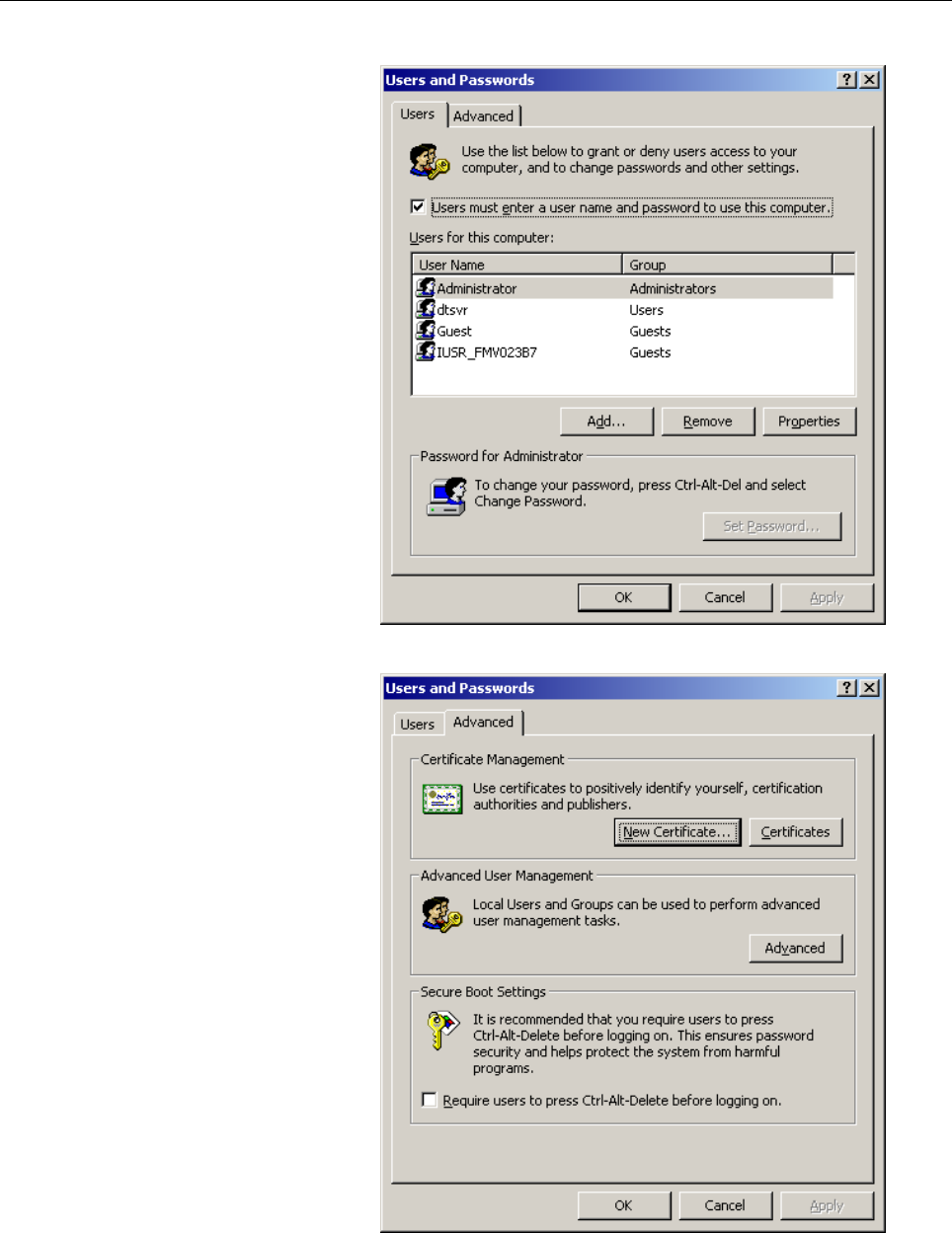
- Page 190B.EXAMPLE OF FTP SERVER SETUP APPENDIX B-64014EN/03 2. Double-click the icon [Users and Passwords]. 3. Click the [Advanced] tab. - 180 -�
- Page 191B-64014EN/03 APPENDIX B.EXAMPLE OF FTP SERVER SETUP 4. Click the [Advanced] button. 5. Double-click [Users]. A list of registered users is displayed. - 181 -�
- Page 192B.EXAMPLE OF FTP SERVER SETUP APPENDIX B-64014EN/03 6. Double-click the user name for which you want to change the password setting. For example, double-click "dtsvr". 7. Check [Password never expires] and then click the [OK] button. The password expiration is stopped. - 182 -�
- Page 193B-64014EN/03 APPENDIX B.EXAMPLE OF FTP SERVER SETUP B.2 SETTING UP FTP SERVER OF Windows XP Professional (FOR INTERNET INFORMATION SERVICE) NOTE Windows XP Home Edition does not have IIS (Internet Information Service). Installing the Internet Information Service 1. Open [Control Panel] of Windows XP
- Page 194B.EXAMPLE OF FTP SERVER SETUP APPENDIX B-64014EN/03 3. Double-click [Add/Remove Windows Components]. 4. Select [Internet Information Services (IIS)], then click the [Details] button to display the [Internet Information Services (IIS)] dialog box. Next, check [File Transfer Protocol (FTP) Service]. -
- Page 195B-64014EN/03 APPENDIX B.EXAMPLE OF FTP SERVER SETUP 5. Click the [OK] button, then return to the previous screen. Next, click [Next]. 6. The dialog box above is displayed, and the necessary files are installed. 7. The installation is completed when the screen above is displayed. - 185 -�
- Page 196B.EXAMPLE OF FTP SERVER SETUP APPENDIX B-64014EN/03 Setting the Internet Information Service 1. Open [Control Panel] of Windows XP Professional. 2. Click [Performance and Maintenance]. - 186 -�
- Page 197B-64014EN/03 APPENDIX B.EXAMPLE OF FTP SERVER SETUP 3. Click [Administrative Tools]. 4. Double-click [Internet Information Services]. - 187 -�
- Page 198B.EXAMPLE OF FTP SERVER SETUP APPENDIX B-64014EN/03 5. Double-click [FTP Site], right-click [Default FTP Site] to display a menu, then select Properties. 6. Select the [Home Directory] tab to display the [Home Directory] property sheet. Check [Read] and [Write] in [FTP Site Directory]. In [Directory
- Page 199B-64014EN/03 APPENDIX B.EXAMPLE OF FTP SERVER SETUP 7. Then, click the [OK] button. In the standard [Default FTP Site], the directory \Inetput\ftproot (on the drive where Windows XP is installed) is the home directory, and only the directories under the home directory can be accessed. To use a direc
- Page 200B.EXAMPLE OF FTP SERVER SETUP APPENDIX B-64014EN/03 Login user setting 1. Open [Control Panel] of Windows XP Professional. 2. Double-click the icon of [User Accounts]. - 190 -�
- Page 201B-64014EN/03 APPENDIX B.EXAMPLE OF FTP SERVER SETUP 3. Click [Create a new account], then enter a desired user name. 4. Click the [Next] button, then set an account type. The access right set here can affect the capability to read from and write to a file in FTP-based communication. Use care when se
- Page 202B.EXAMPLE OF FTP SERVER SETUP APPENDIX B-64014EN/03 5. Click the [Create Account] button, then the creation of an account is completed. 6. For password setting, click the previously created account in [or pick an account to change]. (The FTP server cannot be accessed without setting a password. So,
- Page 203B-64014EN/03 APPENDIX B.EXAMPLE OF FTP SERVER SETUP 7. Click [Create a password], then enter a password for the specified user name. 8. Click the [Create Password] button to register the entered password. By using the account registered this time, the user can log in to the FTP server. - 193 -�
- Page 204B.EXAMPLE OF FTP SERVER SETUP APPENDIX B-64014EN/03 Stopping password expiration for a login user If the password expiration is not stopped, the Data Server will not be able to communicate with the FTP server at the time of expiring the password. If you are necessary, stop the password expiration. I
- Page 205B-64014EN/03 APPENDIX B.EXAMPLE OF FTP SERVER SETUP Confirming the Firewall function of Windows XP Because the Internet Connection Firewall function is included in the Windows XP Professional, the Data Server cannot communicate with the FTP server. If the FTP connection cannot be established, confir
- Page 206B.EXAMPLE OF FTP SERVER SETUP APPENDIX B-64014EN/03 2. Click the icon of [Network and Internet Connections]. 3. Click the icon [Network Connections]. - 196 -�
- Page 207B-64014EN/03 APPENDIX B.EXAMPLE OF FTP SERVER SETUP 4. Right-click the icon [Local Area Connection] to display the menu. Then, select Properties. 5. Select the [Advanced] tab. - 197 -�
- Page 208B.EXAMPLE OF FTP SERVER SETUP APPENDIX B-64014EN/03 6. If [Internet Connection Firewall] is not checked, the Internet Connection Firewall function does not work. Then, the following confirmations are not necessary. 7. If [Internet Connection Firewall] is checked, click the [Settings…] button. 8. If
- Page 209B-64014EN/03 APPENDIX B.EXAMPLE OF FTP SERVER SETUP 9. Select the [ICMP] tab. - 199 -�
- Page 210B.EXAMPLE OF FTP SERVER SETUP APPENDIX B-64014EN/03 10. If the [Allow incoming echo request] check-box is not checked, the Data Server function cannot find the FTP server at the start of communication. At the start of communication of Data Server, if the message “[FTP] (IP-address) IS NOT AVAILABLE”
- Page 211B-64014EN/03 APPENDIX B.EXAMPLE OF FTP SERVER SETUP Confirming the firewall function when Windows XP (Service Pack 2) is used When Windows XP Professional (Service Pack 2) is used, a different firewall setting procedure is used. 1. Open [Control Panel] of Windows XP Professional. 2. Double-click [Se
- Page 212B.EXAMPLE OF FTP SERVER SETUP APPENDIX B-64014EN/03 3. Click [Windows Firewall] displayed at the bottom. - 202 -�
- Page 213B-64014EN/03 APPENDIX B.EXAMPLE OF FTP SERVER SETUP 4. Select the [Advanced] tab. - 203 -�
- Page 214B.EXAMPLE OF FTP SERVER SETUP APPENDIX B-64014EN/03 5. Click the [Settings] button of [ICMP]. 6. If [Allow incoming echo request] is not checked, check it, and click the [OK] button. This allows a response to be made to PING from other devices. - 204 -�
- Page 215B-64014EN/03 APPENDIX B.EXAMPLE OF FTP SERVER SETUP 7. Select the [Exceptions] tab. 8. Click the [Add Port] button, and make settings as follows: - 205 -�
- Page 216B.EXAMPLE OF FTP SERVER SETUP APPENDIX B-64014EN/03 9. Click the [OK] button. - 206 -�
- Page 217B-64014EN/03 APPENDIX C.EXAMPLE OF SETTING UP DNS/DHCP C EXAMPLE OF SETTING UP DNS/DHCP This appendix describes the method of setting up the DNS/DHCP server of Windows 2000 Server. Example of setting a simple network An example of setup in a network configuration that satisfies the following conditi
- Page 218C.EXAMPLE OF SETTING UP DNS/DHCP APPENDIX B-64014EN/03 C.1 EXAMPLE OF SETTING UP DHCP SERVER OF Windows 2000 Server 1. Activating the Microsoft administrative console (DHCP) Click [Programs] → [Administrative Tools] → [DHCP]. 2. Adding a scope Click [Action] → [New Scope] to start “New Scope Wizard”
- Page 219B-64014EN/03 APPENDIX C.EXAMPLE OF SETTING UP DNS/DHCP Enter "factory" as [Name], and enter "FACTORY" as [Description]. Click the [Next] button. Enter “192.168.0.10” as [Start IP address], enter “192.168.0.29” as [End IP address], enter “24” as [Length], and enter “255.255.255.0” as [Subnet mask]. C
- Page 220C.EXAMPLE OF SETTING UP DNS/DHCP APPENDIX B-64014EN/03 Click the [Next] button without entering any data. Keep "8" days unchanged as Period, then click the [Next] button. Keep [Yes, I want to configure these options now] selected, and click the [Next] button. - 210 -�
- Page 221B-64014EN/03 APPENDIX C.EXAMPLE OF SETTING UP DNS/DHCP Click the [Next] button without entering any data. Enter “192.168.0.254” as IP Address, then click [Add]. Click the [Next] button. Click the [Next] button without entering any data. - 211 -
- Page 222C.EXAMPLE OF SETTING UP DNS/DHCP APPENDIX B-64014EN/03 Keep [Yes, I want to activate this scope now] selected, and click the [Next] button. Click [Finish]. - 212 -�
- Page 223B-64014EN/03 APPENDIX C.EXAMPLE OF SETTING UP DNS/DHCP 3. Adding a scope option Click [Scope[192.168.0.0]factory], then click [Scope Options] → [Action] → [Configure Options]. From the available options, find and check [DNS Domain Name]. Then, enter "factory" as String value. Click the [OK] button.
- Page 224C.EXAMPLE OF SETTING UP DNS/DHCP APPENDIX B-64014EN/03 4. Enabling Dynamic DNS Click [Scope[192.168.0.0]factory] → [Properties] → [DNS]. Check [Always update DNC] and [Enable updates for DNS clients that do not support dynamic update]. Click the [OK] button. This completes DHCP server setting. - 214
- Page 225B-64014EN/03 APPENDIX C.EXAMPLE OF SETTING UP DNS/DHCP C.2 EXAMPLE OF SETTING UP DNS SERVER OF Windows 2000 Server 1. Activating the Microsoft administrative console (DNS) Click [Programs] → [Administrative Tools] → [DNS]. 2. DNS server configuration Click [Action] → [Configure the server] to start
- Page 226C.EXAMPLE OF SETTING UP DNS/DHCP APPENDIX B-64014EN/03 Keep [This is the first DNS server on this network] selected, and click the [Next] button. Keep [Yes, create a forward lookup zone], and click the [Next] button. Keep [Standard primary] selected, and click the [Next] button. - 216 -�
- Page 227B-64014EN/03 APPENDIX C.EXAMPLE OF SETTING UP DNS/DHCP Enter "factory." as Name. (Do not fail to enter "." after "factory".) Click the [Next] button. Keep “factory.dns” unchanged, and click the [Next] button. Keep [Yes, create a reverse lookup zone] selected, and click the [Next] button. - 217 -
- Page 228C.EXAMPLE OF SETTING UP DNS/DHCP APPENDIX B-64014EN/03 Keep [Standard primary] selected, and click the [Next] button. Enter “192.168.0” as Network ID. Click the [Next] button. Keep “0.168.192.in-addr.arpa.dns” unchanged, and click the [Next] button. - 218 -
- Page 229B-64014EN/03 APPENDIX C.EXAMPLE OF SETTING UP DNS/DHCP Click the [Finish] button. - 219 -�
- Page 230C.EXAMPLE OF SETTING UP DNS/DHCP APPENDIX B-64014EN/03 3. Enabling Dynamic DNS Right-click [Forward Lookup Zones] → [factory]. Click [Properties]. For [Allow dynamic updates?], select [Yes]. Click the [OK] button. This completes DNS server setting. - 220 -
- Page 231B-64014EN/03 APPENDIX D.FTP CLIENT OPERATION D FTP CLIENT OPERATION This appendix describes the method of operating an FTP client that operates on the host computer to function as a communication destination for the Data Server functions. - 221 -�
- Page 232D.FTP CLIENT OPERATION APPENDIX B-64014EN/03 D.1 OPERATION USING THE FTP COMMAND Login 1 Enter "ftp IP-address-of-NC or host-name" at the command prompt. 2 Enter a user name. 3 Enter a password. 4 The message, "230 User logged in, proceed." indicates that the login process has been completed success
- Page 233B-64014EN/03 APPENDIX D.FTP CLIENT OPERATION PUT (sending a file to the FTP server) 1 Enter "put host-file-name hard-disk-file-name." MPUT (sending files to the FTP server) 1 Enter "mput host-file-name (including a wildcard character)." DIR (acquiring a list of files of the FTP server) 1 Enter dir.
- Page 234D.FTP CLIENT OPERATION APPENDIX B-64014EN/03 TYPE (confirming the transfer type of the FTP client) 1. Enter type. 2. Whether the ascii mode or binary mode is set can be determined. ASCII, BIN (changing the transfer type of the FTP client) 1. Entering bin can change the mode to the binary mode. 2. En
- Page 235B-64014EN/03 APPENDIX D.FTP CLIENT OPERATION D.2 SECURITY UNBLOCKING IN Windows XP (Service Pack 2) When an attempt is made to start FTP communication for the first time in Windows XP (Service Pack 2), the security alert shown below may appear. If the alert appears, consult with the network administ
- Page 236
- Page 237B-64014EN/03 INDEX INDEX
100BASE-TX CONNECTOR (CD38R) PIN ELECTRICAL NOISE COUNTERMEASURES .........134 ASSIGNMENTS........................................................... 129 ERROR MESSAGES DISPLAYED DURING PARAMETER SETTING ...............................................80 Erro - Page 238INDEX B-64014EN/03
Selecting an Inquiry Destination ...................................114 LEADING OUT THE Ethernet CABLE....................... 128 Separating Signal Lines.................................................134 LED Indications and Meanings..................................... 145 S - Page 239Revision Record FANUC FAST Ethernet / FAST Data Server For FANUC Series 30i/300i, 31i/310i, 32i/320i-MODEL A OPERATOR’S MANUAL (B-64014EN) • Addition of such as NC program input/output on the 03 Aug., 2005 Data Server functions • Correction of errors • Addition of the machine remote diagnosis functi
- Page 240