FANUC PMC Simulator, Operator Additional Manual Page 37
Additional Manual
FANUC PMC Simulator
Operator’s Manual
01 05.08.01
T.Maruyama
New registration
A-90139EN/01
EDIT
DATE
DESIG.
DESCRIPTION
37/70
DRAW.NO.
I/O button
There are two kinds of buttons, that is, the input button and the output
button. Even if the forcing of I/O is not effective, forcing of input
button becomes possible.When the forcing of I/O is effective, forcing of
output button becomes possible.The symbol set to ladder is displayed in
the I/O button.
Input button
Input ON Input OFF
Output button
Output ON Output OFF
Fig.4.2.5 (l) I/O button
As for F and X address, the input button is displayed in PMC simulator
(30i/31i/32i-A PMC).As for F,M and X address, the input button is
displayed in PMC simulator(PMC-SB7). Only X address is displayed as
the input button in coordinated CNC/PMC simulator mode.
To sum up, the display form of the bit address is as follows.
Table 4.2.5(a) I/O button
Operation
mode
Button
PMC simulator
(30i/31i/32i-A PMC)
PMC simulator
(PMC-SB7)
Coordinated
CNC/PMC simulator
mode
Input button F,X F,M,X X
Output button A,C,D,E,G,K,M,N,R
,S,T,U,V,W,Y
A,C,D,E,G,K,N,R,S,
T,U,V,W,Y
A,C,D,E,F,G,K,M,N,
R,S,T,U,V,W,Y
Note
To change the state of the signal set to the output
button, set the I/O operation panel to the forcing
mode.
Contents Summary of FANUC PMC Simulator, Operator Additional Manual
- Page 1FANUC PMC Simulator Operator’s Manual Type of applied technical documents FANUC PMC Simulator Name Operator’s Manual Spec. No. /Ed. A-90139EN/01 Summary of Change New, Add, Group Name/Outline Applied Date Correct, Delete Basic Function New Aug. 2005. Optional Function Unit Maintenance Parts Notice C
- Page 2FANUC PMC Simulator Operator’s Manual Contents 1 INTRODUCTION ....................................................................................................................................... 4 1.1 FEATURES OF PMC SIMULATOR.......................................................................
- Page 34.3.1 Display mode ................................................................................................................. 38 4.3.2 Picture mode.................................................................................................................. 40 4.3.3 Window mode ..........
- Page 41 INTRODUCTION This manual explains the operation of "PMC simulator" that is the PMC simulation software for the PC. See the manual of PMC Programming Manual about the programming and operation of PMC. • FANUC Series 30i/31i/32i-A PMC PROGRAMMING MANUAL • FANUC PMC LADDER LANGUAGE PROGRAMMING MANUAL
- Page 5In addition, the following debugging of ladder that cooperates with the CNC simulator is possible in the coordinated CNC/PMC simulator mode(3.). 30i/31i/32i-A works in this mode. • Operation of CNC screens, diagnosis and maintenance screens of built-in PMC • Debugging of ladder that uses window func
- Page 6• The debugging ladder that cooperates with the CNC simulator is possible in the coordinated CNC/PMC simulator mode. Display and operation of CNC screen Ladder using the functional instruction related to CNC Ladder using the signal related to CNC(G,F) • The correspondent functions of the CNC/PMC sim
- Page 7• The following function codes of the window functions are not supported. When the window function is executed, the completion code and the data area after executing the window instruction reaches the following values. Table 1.1.2 (b) Unsupported window function list Function Description Completion
- Page 8Simulator for PMC-SB7 • About the execution of the ladder The execution cycle time and the timing of the ladder are different from actual PMC. Some error margins of counting up the timers are caused by the difference of running state of actual PMC and the PMC simulator. The override function of the
- Page 9List of correspondent functions The usable functions in each mode of the simulator are summarized in the next table. Table 1.1.2 (c) supported function list Mode PMC simulator PMC simulator Coordinated (30i/31i/32i-A (PMC-SB7) CNC/PMC Function PMC) simulator mode Ladder execution Cooperating with FA
- Page 102 SETUP This chapter describes the operating environment of PMC simulator. This chapter also describes how to set up PMC simulator to make software ready for use. 2.1 OPERATING ENVIRONMENT Using this product requires the environment described below. OS : Windows 2000(SP4) or WindowsXP Home/Professio
- Page 112.2 INSTALLATION AND UN INSTALLATION This chapter explains how to install the PMC Simulator and its attached programs in your PC, as well as how to uninstall them from it. The CD-ROM disk is common to the PMC simulator and the CNC simulator. Note 1 Do not insert the USB protect key in the PC until t
- Page 123-1 The Microsoft .NET Framework1.1 installer automatically starts. After it has started, proceed with the following steps. 3-2 When installation starts, the following message appears. Then click
. Fig.2.2.1 (a) Confirmation message 3-3 The "License Agreement" window automatically starts up; se - Page 133-4 Installation of Microsoft .NET Framework1.1 starts. Fig.2.2.1 (c) Install-in-Progress window 3-5 When installation ends, the following message appears. Then click
. Fig.2.2.1 (d) Install Completion window 3-6 In a while, the Microsoft .NET Framework1.1 Service Pack 1 installer automatically - Page 143-7 The "License Agreement" window automatically starts up; select "Agree" and click . Fig.2.2.1 (f) Installer start window 3-8 Installation of Microsoft .NET Framework1.1 Service Pack 1 starts. Fig.2.2.1 (g) Install-in-Progress window 3-9 When installation ends, the following message appe
- Page 153-10 The request message of restart appears. Then click
. Fig.2.2.1 (i) Confirmation message 4 Starting setup and confirming the license agreement of FANUC simulator 4-1 Insert the CD-ROM into the CD drive. After restarting, FANUC simulator installer starts. If it does not automatically start, - Page 164-2 In the "Select the program features" window, select the program and click
. Fig.2.2.1 (k) Select the program features window 4-3 In the "Select Installation Folder" window, specify the folder and click . Fig.2.2.1 (l) Select Installation Folder window FANUC PMC Simulator Operator’s M - Page 174-4 After the "Confirm Installation" window appears, click
. Fig.2.2.1 (m) Confirm Installation window 4-5 Installation of FANUC simulator starts. Fig.2.2.1 (n) Install-in-Progress window FANUC PMC Simulator Operator’s Manual 01 05.08.01 T.Maruyama New registration DRAW.NO. A-90139EN/01 EDIT D - Page 184-6 When installation ends, the following window appears. Then click
. This ends the installation procedure. Fig.2.2.1 (o) Installation Comple window Note When the FANUC Simulator is installed, the driver for using the USB protector is also installed at the same time. 2.2.2 About the USB prot - Page 19There are individual keys for the CNC simulator and PMC simulator. To operate in PMC simulator (30i/31i/32i-A PMC) mode, insert the key for the PMC simulator. To operate in coordinated CNC/PMC simulator mode (30i/31i/32i-A PMC), insert the keys for the CNC simulator and PMC simulator. 2.2.3 Uninstal
- Page 203 Confirming un-installation 3-1 A dialog box appears, asking whether you really want to uninstall the program. Select
. Fig.2.2.3 (b) Confirmation message The installed files, folders, and start menu items are deleted, and the original system settings are restored. Un-installation then ends. N - Page 213 BASICS This chapter describes the basic items which the user should understand before using PMC simulator. 3.1 START AND EXIT This section describes how to start and exit PMC simulator. 3.1.1 Starting PMC simulator First of all, insert the supplied protect key into the USB port. On the start menu,
- Page 223.1.2 Exiting PMC simulator There are the following two kinds of operations depending on the display mode of the simulator. PMC simulator, Window mode of CNC/PMC simulator: On the [File] menu, click [Exit]. Alternatively, click (
button) in the upper right corner of the parent window. Picture - Page 233.2 DISPLAY OF VERSION INFORMATION This section describes how to display the version information of this software for purposes of, for example, maintenance. Select [Help] - [About]. Fig.3.2 Version information FANUC PMC Simulator Operator’s Manual 01 05.08.01 T.Maruyama New registration DRAW.NO. A-9
- Page 244 SCREEN AND OPERATION OF PMC SIMULATOR This chapter explains the screens and the operations of the PMC simulator in each display mode. 4.1 OPERATION MODE OF THE SIMULATOR There are three kinds of operation modes in PMC simulator. 1. PMC simulator(30i/31i/32i-A PMC) 2. PMC simulator(PMC-SB7) 3. Coor
- Page 25Operation mode and display screen of simulator The different points of the display screens that can be operated according to the operation mode of the simulator are as follows. Table 4.1 (b) Operation mode of simulator and display mode Operation PMC simulator PMC simulator Coordinated mode (30i/31i/
- Page 264.2 PMC SIMULATOR MODE(30i/31i/32i-A PMC, PMC-SB7) 4.2.1 Window names and functions This section describes the names and functions of the windows displayed in the PMC simulator mode. As shown in the figure below, child windows such as the I/O operation panel are displayed within the parent window. P
- Page 27• Child window Child windows are displayed within the parent window. Child windows are used for displaying ladder execution status and displaying and editing I/O operation panel, etc. 4.2.2 Main menu The composition of menu is as follows. Table 4.2.2 Menu list Main menu Submenu Reference File Import
- Page 284.2.4 Ladder execution status window Execution state of the ladder of PMC is displayed. Title information Communication status Alarm with FANUC LADDER-III Ladder execution status Ladder run/stop Fig.4.2.4 Ladder execution status window • Title information Displays the information of the title data i
- Page 29• Ladder run/stop It is a button for running and stopping the ladder. :Ladder run :Ladder stop • Communication with FANUC LADDER-III Displays the communication with FANUC LADDER-III. :Connecting :Disconnecting 4.2.5 I/O operation panel window The I/O operation panel window is to display the state of
- Page 30Fig.4.2.5 (a) I/O operation panel window of simulator start 2. To newly add the address of I/O signal in I/O operation panel, select [Tool] - [I/O Operation Panel Setting]. The following setting dialog is displayed. Fig.4.2.5 (b) I/O operation panel setting dialog FANUC PMC Simulator Operator’s Manu
- Page 313. Right-click on the I/O operation panel setting node, and select “Add new page”. Fig.4.2.5 (c) Add new page 4. Set the page by page node. (Page2 here) Fig.4.2.5 (d) I/O page setting FANUC PMC Simulator Operator’s Manual 01 05.08.01 T.Maruyama New registration DRAW.NO. A-90139EN/01 EDIT DATE DESIG.
- Page 325. Right-click on page node (Page2 here), and select “Add new address”. Fig.4.2.5 (e) Add new address 6. When selecting the address data node of each address data , the address data setting dialog is displayed, and then set the address data. Fig.4.2.5 (f) Address data setting dialog FANUC PMC Simula
- Page 33Contents of I/O operation panel setting dialog I/O operation panel setting node Page node Address data node Fig.4.2.5 (g) I/O operation panel setting dialog • I/O Operation Panel Setting node It is possible to do the following operations from the pop-up menu of the I/O operation panel setting node.
- Page 34Moreover, the address data node can be copied by dragging with right button and moved by dragging with left button by using the drag & drop of the mouse operation. Content of I/O operation panel setting dialog Fig.4.2.5 (h) I/O operation panel setting • Address notation Specify whether the content o
- Page 35Address data setting dialog Fig.4.2.5 (j) Address data setting • Title The setting content is displayed in the title of address data node when setting it. The address is displayed if this is the blank. • PMC address Specify the first PMC signal to display by address or by symbol. With the multi-path
- Page 36• Data type Select among signed, unsigned, and hexadecimal. • Switch type Select the switch type of the input signal. alternate The state changes every time when on and off button is pushed. momentary The state is on while the button is pushed but the state is off when button is separated. • Show th
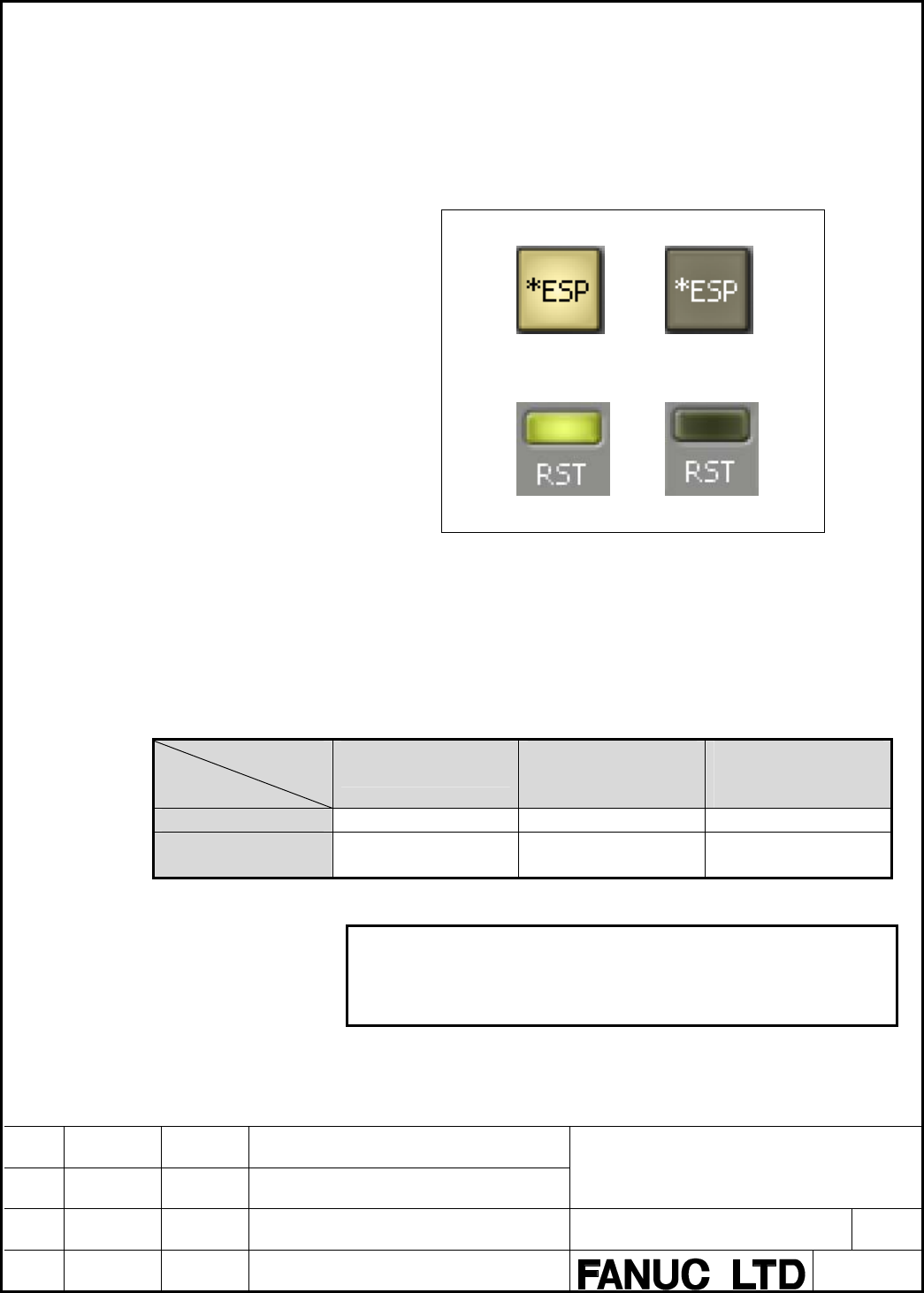
- Page 37I/O button There are two kinds of buttons, that is, the input button and the output button. Even if the forcing of I/O is not effective, forcing of input button becomes possible.When the forcing of I/O is effective, forcing of output button becomes possible.The symbol set to ladder is displayed in t
- Page 38Display and setting of byte, word, and dword The display and the setting of byte, word, dword are operated in the edit box. Display content of I/O The address and the symbol information of the I/O signal are displayed with the tool chip. 4.3 COORDINATED CNC/PMC SIMULATOR MODE This section describes
- Page 39Features of window mode This mode is started in the display form of usual Windows program without image of an actual CNC. It is possible to change the size and the position of the window. Fig.4.3.1 (b) Appearance of window mode Comparison of display modes The following table shows the comparisons of
- Page 404.3.2 Picture mode This section describes the menu and the operation in picture mode. Main menu The composition of menu in picture mode is as follows. Table 4.3.2 Menu list Main menu Submenu Reference Display Mode 4.3.4 Method of switching display mode CNC Display Size MDI Key Window Size PMC I/O Op
- Page 41• As for the I/O operation panel, some screens and the operations are different. Note Refer to " FANUC CNC Simulator for PC OPERATOR'S MANUAL" appended to installation CD for basic operation in the picture mode such as the operations of CNC screen and MDI key. I/O operation panel To display the I/O
- Page 42• Page name Display the title of the displayed page. • Forcing When the forcing of I/O is effective, it is possible to change the value of the PMC address on the I/O operation panel. Forcing I/O becomes effective by applying the check on "Forcing" on the I/O operation panel. • Symbol display Switch
- Page 434.3.3 Window mode This section describes the menu and the operation in the window mode. Main menu The composition of menu in the window mode is as follows. Table 4.3.3 Menu list Main menu Submenu Reference File Exit 3.1.2 Exiting PMC simulator View Display Mode 4.3.4 Method of switching display mode
- Page 444.3.4 Method of switching display mode This section describes the method of switching "Picture mode" and "Window mode". Switching from the picture mode to the window mode Select the [Display Mode] - [Window Mode] by the pop-up menu. Fig.4.3.4 (a) Pop-up menu “Display mode switch” The message is disp
- Page 45Switching from the window mode to the picture mode Select the [Display Mode] - [Picture Mode] by the pop-up menu. Fig.4.3.4 (c) Main menu “Display mode switch” The message is displayed, then click < OK >. "Picture mode" is displayed when started next time. Fig.4.3.4 (d) Message after setting Note Af
- Page 465 VARIOUS SETTINGS This chapter describes various setting methods to use the PMC simulator according to customer's environment of CNC/PMC. 5.1 OPTION PARAMETER SETTINGS Set the CNC/PMC option parameters for the simulator. Set the option parameters with a dedicated application separate from the simul
- Page 47The following screen is displayed when starting. Click
button to exit. Fig.5.1.1 (b) Option parameter setting Note Option settings can be made to the Simulator when it is active; the Simulator(30i/31i/32i-A) must have been previously started. The following messages is displayed and the prog - Page 485.1.2 Operation method Set the options according to the following procedures. 1. Select an option to use and place a check mark. Click the check box located to the left of an option name or double-click the option name and the check mark is placed in the check box. 2. Click the
button and the s - Page 495.2 MACHINE COMPOSITION SETTINGS This section explains the settings of machine composition of the simulator. The machine composition is a collection of parameters and other various settings for the simulator.Multiple machine compositions can be registered and switched between them if needed.For exam
- Page 505.3 PMC OPTION SETTINGS Following PMC option settings are available. Select [Tool] – [Option]. Table 5.3 Option setting list Tab General SB7 Operation mode PMC simulator • Language (30i/31i/32i-A PMC) • Ethernet port number PMC simulator • Language • E address (PMC-SB7) • Ethernet port number nonvol
- Page 515.4 PMC SIMULATOR(PMC-SB7) SETTINGS PMC-SB7 has the following setting. ・Nonvolatile setting of E address 5.4.1 E address nonvolatile setting E address becomes nonvolatile by the option. Assign E addresses to volatile or nonvolatile memory locations. Select [Tool] – [Option] – [SB7] tab and select wh
- Page 526 INPUT/OUTPUT AND BACKUP OF PMC DATA Input/output and back up the following PMC data are operated by the PMC I/O operation. Their equivalents are operated by import, export and back up menu on the PMC simulator. • Ladder • PMC parameter • PMC multi-language message(30i/31i/32i-A PMC) It is also pos
- Page 532. Select an importing file. Fig.6.1.1 (b) Open file 3. Click the
button. 4. After importing, operate the backup menu to store the ladder and PMC multi-language message data to the selected machine composition. 6.1.2 Export procedure 1. Select [File] – [Export] and select the program and PMC - Page 541. Select [File] – [Backup] and select the program and PMC path. At 30i/31i/32i-A PMC, select the PMC path. Fig.6.1.3 (a) Menu “Backup” 2. Click the < Yes > button. Fig.6.1.3 (b) Confirmation message FANUC PMC Simulator Operator’s Manual 01 05.08.01 T.Maruyama New registration DRAW.NO. A-90139EN/01
- Page 556.2 I/O OPERATION IN COORDINATED CNC/PMC SIMULATOR MODE Input/output and back up the PMC data on the I/O screen of built-in PMC screen. Fig.6.2 I/O screen of built-in PMC The target folder for I/O is "MEMCARD" in the folder in which the application is installed. Example: Install folder: "C:¥Program
- Page 567 COMMUNICATION LADDER-III WITH FANUC 7.1 OUTLINE The online connection with FANUC LADDER-III is possible in PMC simulator by using the network communication function. The following online functions equal with the case where FANUC LADDER-III is connected with actual PMC can be used. • Monitor displa
- Page 577.2 ETHERNET SETTING IN PC Basic Ethernet setting such as IP address etc. depends on the PC environment on which PMC simulator is executed. Note IP address should be allotted to the PC and TCP/IP connection should be effective. Therefore, it is necessary to connect the PC with an Ethernet router or
- Page 58• Ethernet function The setting is not necessary. The Ethernet function can be used at any time. Coordinated CNC/PMC simulator mode • Port number Specify the port number of Ethernet. Select [Tool] - [Option] – [General], and set the port number. • Ethernet function When the CNC/PMC simulator is used
- Page 597.4 CONNECT THE SIMULATOR ON THE SAME PC When the simulator and FANUC LADDER-III are connected on the same PC, the setting of FANUC LADDER-III and the PC are needed. Connection FANUC LADDER-III Simulator Fig.7.4 (a) Connected on the same PC PC setting When the simulator and FANUC LADDER-III are conn
- Page 602. Select [Setting] tab, and move "LOCALHOST" to “Use device” setting by above 1. Fig.7.4 (c) Use device setting FANUC PMC Simulator Operator’s Manual 01 05.08.01 T.Maruyama New registration DRAW.NO. A-90139EN/01 EDIT DATE DESIG. DESCRIPTION 60/70
- Page 617.5 CONNECT THE SIMULATOR ON DIFFERENT PCS When the simulator and FANUC LADDER-III are connected on different PCs, the IP address of the connected PC on which the simulator works should be specified by the communication setting of FANUC LADDER-III. Connection Simulator FANUC LADDER-III Fig.7.5 Conne
- Page 628 SIGNAL OPERATION REPLAY FUNCTION 8.1 OUTLINE This function is to record the changing input signals operated on the I/O operation panel to simplify the manual input operation of the signals, and to play the recorded contents. Moreover, it is possible to input/output the recorded contents with the f
- Page 638.2 SIGNAL OPERATION REPLAY SCREEN This section describes the signal operation replay window as follows. Fig.8.2 Signal operation replay function window • State Display the state of a current operation. Playing. Recording. Stopping. FANUC PMC Simulator Operator’s Manual 01 05.08.01 T.Maruyama New re
- Page 64Pausing. • Comment Put the comment on the recording data. • Step interval to record Specify “Real time” or “Constant” to the interval of the operated time for the operation under the record. • Real time: Record the interval time to reproduce the input operation in real time. • Constant: Record inter
- Page 65• The current step number per the entire number of steps is shown. There is no limitation in the entire step number. • (Play button) Starts replaying of the signal according to the contents of memorized steps in the memory. • (Pause button) Temporarily stops replaying of the signal. • (Stop button)
- Page 668.3 FILE OPERATION This section describes the file operation of the signal operation file. The file operation is operated by the toolbar. • (New) Newly records the signal operation. The memorized operation record is cleared. When the operation record has already been memorized, the following message
- Page 678.4 SIGNAL OPERATION FILE FORMAT The signal operation file is CSV(Comma Separated Value) file. The file is divided into the header and the command part. The file can be displayed and be edited by the text editor, the word pad and the spreadsheet corresponding to CSV such as Microsoft Excel. 1. Heade
- Page 68・ Specify the address following the wait. Two or more addresses can be specified in the same line, and those addresses are input at the same timing. The maximum number of addresses that can be specified at the same time are 32 points. ・ Specify the signal value following the address. The hexadecimal
- Page 69When playing the file of Fig.8.4 (a) or Fig.8.4 (b), the signals change as follows. Fig.8.4 (c) Signal change • About the error ・ When any erroneous line exists, the file is invalid. FANUC PMC Simulator Operator’s Manual 01 05.08.01 T.Maruyama New registration DRAW.NO. A-90139EN/01 EDIT DATE DESIG.
- Page 708.5 CONVERTING TRACED SIGNALS Select the necessary signal from the trace result data by the trace function of built-in PMC and FANUC LADDER-III, and convert it to the signal record. 8.5.1 Change procedure 1. Select "Open" from the toolbar. 2. Specify the file name and select
. Fig.8.5.1 (a) O