2 CPU 3-path control function Additional Manual Page 51
Additional Manual
50
/
50
FANUC Series 16i-TB
2 CPU 3-path control function
Specifications
A
-78884E
ED. DATE DESIG. DESCRIPTION
TITLE
DRAW.NO.
01 Aug.01.’02 Newly registered
SHEET
Fine Acc & Dec control O
HRV control O
High speed HRV control O
Inch/metric conversion
✩
Interlock All axes/each axis/each direction/block
start/cutting block start
O
Machine lock All axes/each axis O
Emergency stop O
Over travel O
Stored stroke check 1 O
Stroke limit external setting -
Stored stroke check 2 -
Stored stroke check 3 -
Stored stroke check 2, 3
✩
Stroke limit check before move
✩
Chuck and tail stock barrier
✩
Mirror image Each axis O
Follow-up O
Servo off/mechanical handle feed O
Chamfering on/off O
Interference check
✩
Interference check for rotary area
✩
Unexpected disturbance torque
detection function
✩
Fine torque sensing -
Rotary axis control
✩
Position switch
✩
High-speed position switch
✩
Direction-dependent type high-speed
position switch
✩
Linear scale I/F with absolute address
reference mark
✩
Temporary absolute coordinate setting
✩
Dual check safety
✩
Operation
Automatic operation (memory) O
MDI operation O
DNC operation Reader/puncher interface is required.
Simultaneous operation of Multi path is
impossible.
✳
DNC operation with Memory Card PCMCIA Card Attachment is required.
In case of 160i /180i /210i /160is /180is
/210is, this function can not be used.
O
Schedule function -
Program number search O
Sequence number search O
Sequence number comparison and stop
✩
Program restart
✩
Tool retract and recover
✩
Manual intervention and return O
Retraction for rigid tapping -
Buffer register O
Dry run O
Single block O
Jog feed O
Contents Summary of 2 CPU 3-path control function Additional Manual
- Page 1TECHNICAL REPORT (MANUAL) No. TMN 02/075E Date : Aug.01, 2002 General Manager of Software Development Center FANUC Series 16i-TB 2 CPU 3-path control function 1. Communicate this report to: ○ Your information only ○ GE Fanuc-N, GE Fanuc-E FANUC Robotics MILACRON ○ Machine tool builder Sales agency E
- Page 2FANUC Series 16i-TB 2 CPU 3-path control function Specifications < Contents > 1. General..................................................................................................................2 2. Specifications...............................................................................
- Page 31. General 3-path control function is the function to execute three independent machining at the same time. This function is intended for the lathe which cuts the work at the same time on three tool posts. The machining programs for each path are stored into program memories for each path. Before au
- Page 42. Specifications 2.1 System configuration 2.1.1 Hardware For 3-path control system, Sub CPU board and the option of 3 path control function with 2 CPU are need. Main CPU board PMC Servo axes Sub CPU board 8 Path-2 Servo axes Serial 4+4 9.5"LCD/10.4"LCD Path-1 Spindle 2 Path-3 Serial Spindle Analog
- Page 52.1.3 Spindle motors control The maximum number of controllable serial spindle motors is 2 for each path. The 1st and 2nd spindle motors on Main CPU board are for Path-1. The 1st and 2nd spindle motors on Sub CPU board are for Path-2, and the 3rd and 4th spindle motors are for Path-3. Main CPU board
- Page 6(2) Direct DI/DO Address 7 6 5 4 3 2 1 0 X000 X001 X002 X003 ESKIP -MIT2 #1 +MIT2 #1 -MIT1 #1 +MIT1 #1 ZAE #1 XAE #1 X004 SKIP #1 #1 SKIP6 SKIP5 #1 SKIP4 #1 SKIP3 #1 SKIP2 #1 SKIP8 #1 SKIP7 #1 X005 X006 #2 #2 #2 #2 #2 #2 #2 #2 X007 *DEC8 *DEC7 *DEC6 *DEC5 *DEC4 *DEC3 *DEC2 *DEC1 X008 *ESP #1 #1 #1 #
- Page 72.2 Programming 2.2.1 Program Programs are stored into each program memories for each path. The format of program is the FANUC standard format based on EIA format. To control 3-path system, waiting function, Synchronous/composite/superimposed control function and Spindle control function are provide
- Page 8(4) Parameters 7 6 5 4 3 2 1 0 8101 MWB [Data type] : Bit MWB A waiting M code is 0: Buffered. 1: Not buffered. Note) An M code is never buffered when the same M code is specified in the parameters 3411 to 3420 as the M code prevented from buffering. 8110 Waiting M code range (minimum value) 8111 Wa
- Page 9(6) Example When the no-wait signal (G1063.7) is set to 1 and M101 to M103 are specified as waiting M codes, the programs for each paths execute as following. Parameter setting : Parameter 8110 = 101 : Parameter 8111 = 103 Program for Path-1 Program for Path-2 Program for Path-3 O0100; O0200; O0300;
- Page 10(7) Alarms and messages No. Message Description 160 MISMATCH WAITING M-CODE (a) The commands have identical P values but different M codes. (b) The commands have identical M codes but different P values. (c) Both two-path and three-path wait are simultaneously executed. 161 ILLEGAL P OF WAITING (a)
- Page 112.2.3 Synchronous control and composite control (1) Overview 3-path control has three independent control paths. For example, it can be used to control three turrets of a multiple-turret lathe independently. Machining is performed by a path 2 program. Z2 Turret 2 X2 Workpiece 1 Workpiece 2 Z1 Z3 X1
- Page 12(2) Synchronous Control An axis in path 1 or path 2 can be synchronized with another axis in the same path or an axis in the other path. This is realized by issuing the same move commands for one axis (synchronous master axis) to another axis (synchronous slave axis). Using parameter SMRx (bit 0 of
- Page 13(3) Composite Control Move commands can be interchanged between an axis in path 1 or path 2 and an axis in the other path. In other words, when a machining program is executed for one path, actual machining can be performed with an axis in the other path. Coordinate systems can also be switched auto
- Page 14(4) Superimposed Control The superimposed control function adds the amount of movement of an axis (superimposed control master axis) to an axis (superimposed control slave axis) for which ordinary move commands are being executed. This function is similar to synchronous control but differs from it i
- Page 15(d) Feedrate Because the amount of movement of the master axis is added to that of the slave axis, the resulting speed of the slave axis may become much more larger than a normal speed (such as rapid traverse speed specified in a parameter). To solve this problem, it is necessary to set feedrates th
- Page 16(5) Signals (a) Synchronous control axis selection signals SYNC1-8
- Page 17(c) Composite control axis selection signal MIX1-8
- Page 18(e) Synchronous/composite/superimposed control under way signals SYN1O to SYN8O
- Page 19(6) Parameter 7 6 5 4 3 2 1 0 8160 NRS SPE [Data type] Bit SPE The synchronization deviation is: 0: The difference between the positioning deviation of the master axis and that of the slave axis. 1: The difference between the positioning deviation of the master axis and that of the slave axis plus t
- Page 207 6 5 4 3 2 1 0 8162 MUMx MCDx MPSx MPMx OMRx PKUx SERx SMRx [Data type] Bit axis SMRx Synchronous mirror-image control is: 0: Not applied. (The master and slave axes move in the same direction.) 1: Applied. (The master and slave axes move in opposite directions.) SERx The synchronization deviation
- Page 217 6 5 4 3 2 1 0 8163 SCDx SCMx SPSx SPMx MDXx [Data type] Bit axis MDXx In composite control, the current position (absolute/relative coordinates) display indicates: 0: Coordinates in the local system. 1: Coordinates in the other system under composite control. SPMx When synchronous control is start
- Page 227 6 5 4 3 2 1 0 8166 OVL MIX SYN [Data type] Bit SYN The interface of the synchronous control is: 0: Covered 3 paths. 1: Usual 2 paths interface. (Not covered 3rd path control) MIX The interface of the composite control is: 0: Covered 3 paths. 1: Usual 2 paths interface. (Not covered 3rd path contro
- Page 238181 Synchronization error limit of each axis (Synchronous or composite control) [Data type] Two-word axis [Unit of data] Unit of detection [Valid data range] 0 to 32767 When the synchronization deviation detected (SERx of bit #1 parameter No.8162 is set to 1), this parameter specifies the limit of
- Page 248184 Coordinates of reference point of an axis on the coordinate system of another composite control [Data type] Two-word axis [Unit of data] Increment system IS-A IS-B IS-C Unit Millimeter machine 0.01 0.001 0.0001 mm Inch machine 0.001 0.0001 0.00001 inch Rotation axis 0.01 0.001 0.0001 deg [Valid
- Page 25superimposed control and the move pulse of another axis is not superimposed. 8190 Rapid traverse rate of an axis under superimposed control [Data type] Two-word axis [Unit of data] [Valid data range] Valid data range Increment system Unit of data IS-A,IS-B IS-C Millimeter machine 1 mm/min 30 to 2400
- Page 268193 Maximum cutting feedrate under superimposed control [Data type] Two-word [Unit of data] [Valid data range] Valid data range Increment system Unit of data IS-A,IS-B IS-C Millimeter machine 1 mm/min 30 to 240000 30 to 100000 Inch machine 0.1 inch/min 30 to 96000 30 to 48000 Rotation axis 1 deg/mi
- Page 27(7) Alarms and Messages If one of the alarms listed below occurs, it terminates synchronous, composite, and superimposed control for all axes. Number Message Description 225 Synchronous or composite This alarm occurs under either of the following conditions(detected when synchronous, control error.
- Page 282.3 Spindle speed control 2.3.1 General 3-path control has one spindle interface in each path, that is three interfaces as total. For example, a work fixed at one or two spindles can be machined by three tool posts and power tools in same time. Each spindle interfaces (first spindle, second spindle,
- Page 29(4) 2nd and 3rd spindle If 1st spindle is a serial spindle, 2nd and 3rd spindles are also able to use in a 3-path lathe. The 2nd and 3rd spindles are controlled by PMC signals (SIND#1,SIND2#1,SIND3#1,SIND#2,SI ND2#2,SIND3#2, SIND#3,SIND2#3,SIND3#3) or by the multi-spindle control function. If using
- Page 30(b) he relation between the path and the spindle feedback (the state in 3-spindle control and all spindles connected) SP1#1 SP2#1 SP1#2 SP2#2 SP1#3 SP2#3 PC1#1 PC2#1 PC1#2 PC2#2 PC1#3 PC2#3 Path 1 0 1 Path 2 0 1 Path 3 0 1 PC2SLC#1 PC2SLC#2 PC2SLC#3 SLPCA#1 SLPCB#1 SLPCA#2 SLPCB#2 SLPCA#3 SLPCB#3 1
- Page 31(6) Signals (a) Spindle command select signals 7 6 5 4 3 2 1 0 G0063 SLSPB#1 SLSPA#1 G1063 SLSPB#2 SLSPA#2 G2063 SLSPB#3 SLSPA#3 [Classification] Input signal [Function] Selects which spindle receives spindle command of which path. [Operation] Spindle command Spindle command Spindle command on path
- Page 32(b) Spindle feedback select signals 7 6 5 4 3 2 1 0 #1 #1 G0064 SLPCB SLPCA G1064 SLPCB#2 SLPCA#2 G2064 SLPCB#3 SLPCA#3 [Classification] Input signal [Function] Selects which spindle sends the feedback signal of the position coder to which path. [Operation] Spindles on Spindles on Spindles on path 1
- Page 33(c) Spindle select signals 7 6 5 4 3 2 1 0 #1 #1 G0027 SWS3 SWS2 SWS1#1 G1027 SWS3#2 SWS2#2 SWS1#2 G2027 SWS3#3 SWS2#3 SWS1#3 [Classification] Input signal [Function] In the multi-spindle function, it is controlled that S command on CNC is output to which spindle. [Operation] SWS1#1 1: Spindle comma
- Page 34(d) Spindle stop signals 7 6 5 4 3 2 1 0 #1 #1 #1 G0027 *SSTP3 *SSTP2 *SSTP1 G1027 *SSTP3#2 *SSTP2#2 *SSTP1#2 G2027 *SSTP3#3 *SSTP2#3 *SSTP1#3 [Classification] Input signal [Function] In the multi-spindle function, each spindle on each path can be stopped individually by these signals. [Operation] *
- Page 35(e) 2nd position coder select signals 7 6 5 4 3 2 1 0 #1 G0028 PC2SLC G1028 PC2SLC#2 G2028 PC2SLC#3 [Classification] Input signal [Function] These signals select whether to use the feedback of the 2nd position coder. [Operation] PC2SLC#1 1: The feedback of the 2nd position coder is used on path 1. 0
- Page 36(7) Parameter 7 6 5 4 3 2 1 0 3702 ECS ESS EAS ESI EMS [Data type] Bit EMS The Multi-spindle control function is: 0: Used. 1: Not used. ESI The Spindle positioning function is: 0: Used. 1: Not used. EAS The Spindle analog output function is: 0: Used on path 1, path 2, or path 3. 1: Not used. ESS The
- Page 377 6 5 4 3 2 1 0 3706 PCS [Data type] Bit PCS In 2-path or 3-path control, when Multi-spindle control is used on each path, the relation of the selected position coder and the signals SLPCA, SLPCB, and PC2SLC on each path is: 0: As the following table (a). 1: As the following table (b). (a) Parameter
- Page 38(b) Parameter PCS (No.3706#3)=1 SLPCA SLPCB PC2SLC#1 PC2SLC#2 PC2SLC#3 0 1 0 1 0 1 Path 1 1 0 PC1#1 PC2#1 (#1) 0 1 PC1#2 PC2#2 1 1 PC1#3 PC2#3 Path 2 1 0 PC1#1 PC2#1 (#2) 0 1 PC1#2 PC2#2 1 1 PC1#3 PC2#3 Path 3 1 0 PC1#1 PC2#1 (#3) 0 1 PC1#2 PC2#2 1 1 PC1#3 PC2#3 (PC1,2=Position coder 1,2) 2.3.3 Noti
- Page 392.4 Display and edit function 2.4.1 Path selection HEAD(G0063#0) and HEAD2(G0062#7) select which path’s screen is displayed. HEAD(G0063#0) HEAD2(G0062#7) Path 1 0 0 Path 2 1 0 Path 3 0 1 2.4.2 Common screen for whole paths Some screens exist on each path, for example, the parameter screen. And other
- Page 40(b) All position ACTUAL POSITION | | HEAD1 O12345678 N12345 |HEAD2 O12345678 N12345 |HEAD3 O12345678 N12345 (RELATIVE) (ABSOLUTE) | (RELATIVE) (ABSOLUTE) | (RELATIVE) (ABSOLUTE) U1-99999.999 X1-99999.999 |U2-99999.999 X2-99999.999 |U3-99999.999 X3-99999.999 W1-99999.999 Z1-99999.999 |W2-99999.999 Z2
- Page 41(3) Program edit screen PROGRAM | | HEAD1 O12345678 N12345 |HEAD2 O12345678 N12345 |HEAD3 O12345678 N12345 O12345678; |O12345678; |O12345678; N1 |N10 |N100 N2 |N20 |N200 N3 |N30 |N300 N4 |N40 |N400 | | | | | | | | | | | | | | | | | | | | | | | | | | EDIT **** *** *** 12:34:56 HEAD1 PROG CHK NEXT (OP
- Page 422.5 Tool post interference check 2.5.1 General Tool post interference check can decelerate and stop the two tool posts before the tool posts interfere with each other by an incorrect command. And alarms and DO signals are output. Tool post interference check is available for the interference between
- Page 43CNC checks interferenc Parallel axis Parallel axis 2 Parallel axis 1 Parallel axis 1 Facing axis Facing axis CNC does not check the interference of the surface which was surrounded by the dotted line in the above figure. The specifying in the surface of the dotted line is due to the setting of the s
- Page 44(ii) Set (i) and (ii) in the following condition. (i) < (ii) In the example of the left figure, the Parallel axis 2 (i) specifying of the surface which does not Parallel axis 1 check in the interference is the side of the negative ( of the facing axis ). Facing axis (c) (a) Parallel axis 2 (b) Paral
- Page 45Address #7 #6 #5 #4 #3 #2 #1 #0 F0292 ITFCA3 ITFCA2 ITFCA1 [Classification] output signals [Function] These signals indicate whether a movement command was executed that interference might occur between tool posts. [Operation] When each ITFCA* signal is 1, a movement command was executed that interf
- Page 4612504 IDRCH [Data type] Bit IDRCH The plane not to check interference is: 0: the minus side on the vertical plane of the facing axis (width axis) 1: the plus side on the vertical plane of the facing axis (width axis) 12505 Offset amount on the facing axis at the point (i) of the rectangular parallel
- Page 47[Data type] 2-word [Unit of data] Output unit [Valid data range] 0-±99999999 Setting offset amount on each axis at the pair of points ((i), (ii)) on max. 3 rectangular parallelepipeds ((a), (b), (c)) composing the tool post 1. The offset amount is the distance with signs from the machine reference p
- Page 4812580 DRCV2 DRCV1 DRCH [Data type] Bit DRCH The facing axes (width axes) of the interference check #1 (tool post 1 and 2) are: 0: same direction. 1: opposite direction. DRCV1 The parallel axes 1 (length axes) of the interference check #1 (tool post 1 and 2) are: 0: same direction. 1: opposite direct
- Page 4912581 Offset amount of the reference point on machine coordinates between the facing axes of the interference check #1 (tool post 1 and 2). 12582 Offset amount of the reference point on machine coordinates between the parallel axes 1 of the interference check #1 (tool post 1 and 2). 12583 Offset amo
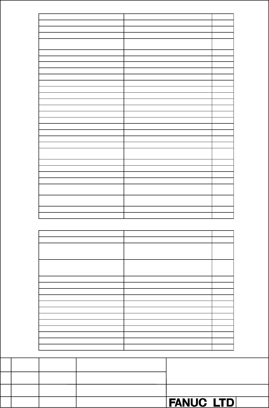
- Page 503. Specifications list for 2 CPU 3-path control Ο : Standard ✩ : Option ✳ : Function included in another option Item Specifications FS16i FS160i FS160is -TB Controlled axis Max. controlled axes 16axes ✩ (Machine controlled axes + Loader Machine 8 axes : Path1 controlled axes) Machine 4 axes : Path2
- Page 51Fine Acc & Dec control O HRV control O High speed HRV control O Inch/metric conversion ✩ Interlock All axes/each axis/each direction/block O start/cutting block start Machine lock All axes/each axis O Emergency stop O Over travel O Stored stroke check 1 O Stroke limit external setting - Stored strok
- Page 52Manual reference position return O Reference position setting without DOG O Reference position setting with ✩ mechanical stopper Reference position shift ✩ Manual handle feed 1 unit/each path ✩ 2 units ✩ 2 units/3 units - Manual handle feed rate ×1, ×10, ×m, ×n ✳ m:0∼127, n:0∼1000 Tool direction han
- Page 53Smooth interpolation It is possible to use this function on ✩ path-1 only. High-precision contour control, AI high-precision contour control, or AI nano high-precision contour control is required. Threading, synchronous cutting O Multiple threading O Threading retract ✩ Continuous threading ✩ Variab
- Page 54Cutting feedrate clamp O Automatic acceleration/deceleration Rapid traverse: linear O Cutting feed: exponential Rapid traverse bell-shaped ✩ acceleration/deceleration Positioning by optimal acceleration ✩ Optimum torque It is possible to use this function on ✩ acceleration/deceleration path-1 only.
- Page 55Max. programmable dimension ±8-digit O Program number O4-digit O O8-digit ✩ Sequence number N5-digit O Absolute/incremental programming Combined use in the same block O Decimal point programming/ pocket O calculator type decimal point programming Input unit 10 time multiply O Diameter/Radius program
- Page 56Scaling It is possible to use this function on ✩ path-1 only. High-precision contour control, AI high-precision contour control, or AI nano high-precision contour control is required. Coordinate system rotation ✩ Three-dimensional coordinate ✩ conversion Tilted working plane command - Programmable m
- Page 57Automatic process determination - Automatic process determination - function B Animated simulation function - Animated simulation function for vertical - lathe C-axis process function - C-axis process function B - Y-axis process function - Back machining function - Balance cut process function Only
- Page 58Spindle synchronous control ✩ Spindle simple synchronous control ✩ Multi spindle control ✩ Spindle positioning ✩ Rigid tapping ✩ Three-dimensional rigid tapping ✩ Rigid tapping by manual handle - Tool function/Tool compensation Tool function O Tool offset pairs ±6 digits 9/16 pairs O ±6 digits 32 ✩
- Page 59Extended tool life management - Tool management function Tool 64 pairs. ✩ Tool management function 240pairs Tool 240 pairs. ✩ Tool management function 1000pairs Tool 1000 pairs. ✩ Add. customized data on Tool Customized data add. 16 pairs. ✩ management function Tool offset value counter input O Tool
- Page 60Editing operation Part program storage length 10m (4Kbyte) - 20m (8Kbyte) - 40m (16Kbyte) O (The actual registrable value might 80m (32Kbyte) ✩ changes according to the registered number of programs and the program 160m (64Kbyte) ✩ sizes.) 320m (128Kbyte) ✩ 640m (256Kbyte) ✩ 1280m (512Kbyte) ✩ 2560m
- Page 61Spindle setting screen Only for αi / α series ✳ Servo waveform display Graphic display circuit is required. ✳ Display of hardware and software O configuration Servo information screen O Spindle information screen Only for αi / α series ✳ Periodic maintenance screen O Maintenance information screen O
- Page 62External machine zero point shift ✩ External data input Including above 3 items ✩ External key input O External program input O External workpiece number search 9999 O External program number search 1 ∼ 9999 ✳ One touch macro call ✩ Memory card input/output O Screen hard copy This function can not b