CNC Setting Tool Operators manual Page 142
Operators manual
B-64174EN/01-1
Title
Draw
No.
Ed. Date Design Description
Date 05.1.21 Design. T.Hosaka Apprv.
12/49
page
FANUC CNC Setting Tool
OPERATOR’S MANUAL
3 OPERATION OF CNC SETTING TOOL
This chapter describes the method of operating the CNC Setting Tool.
3.1 STARTING AND QUITTING
The methods of starting and quitting the CNC Setting Tool are described
below.
Starting
To start the CNC Setting Tool, double-click a desired parameter file in the
file management function.
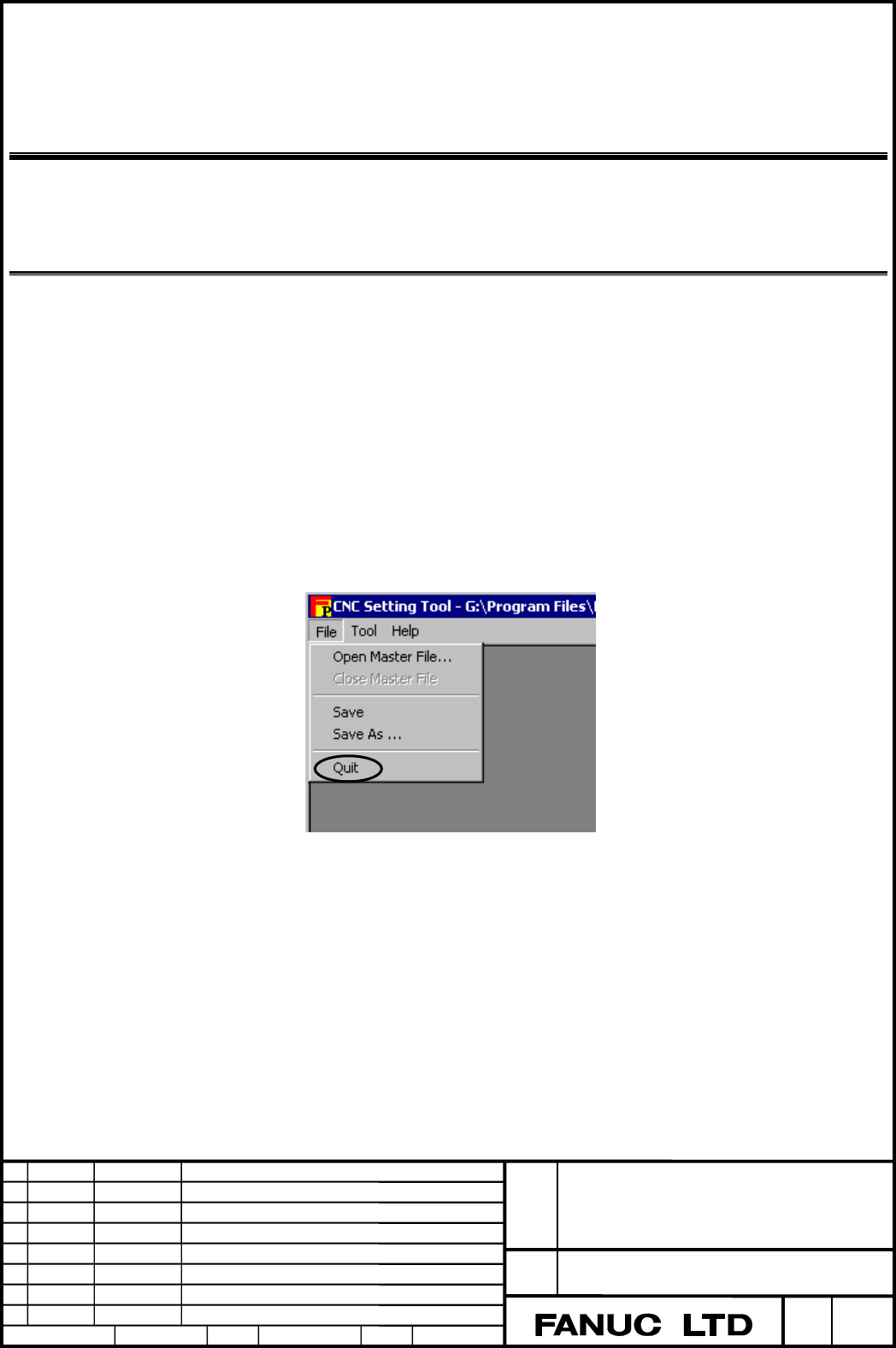
Quitting
The method of quitting the CNC Setting Tool is described below.
Choose [File] then [Quit] from the menu.
Contents Summary of CNC Setting Tool Operators manual
- Page 1FANUC CNC SETTING TOOL OPERATOR’S MANUAL B-64174EN/01
- Page 2• No part of this manual may be reproduced in any form. • All specifications and designs are subject to change without notice. The export of this product is subject to the authorization of the government of the country from where the product is exported. In this manual we have tried as much as possi
- Page 3B-64174EN/01 SAFETY PRECAUTIONS SAFETY PRECAUTIONS This section describes the safety precautions related to the use of CNC units, to ensure safe operation of machines fitted with FANUC CNC units. Read this section carefully before attempting to use any function described in this manual. Users should
- Page 4SAFETY PRECAUTIONS B-64174EN/01 1.1 DEFINITION OF WARNING, CAUTION, AND NOTE This manual includes safety precautions for protecting the user and preventing damage to the machine. Precautions are classified into Warnings and Cautions according to their bearing on safety. Also, supplementary informati
- Page 5B-64174EN/01 SAFETY PRECAUTIONS 1.2 GENERAL WARNINGS AND CAUTIONS WARNING 1 Before operating the machine, thoroughly check the entered data. Operating the machine with incorrectly specified data may result in the machine behaving unexpectedly, possibly causing damage to the workpiece and/or machine
- Page 6SAFETY PRECAUTIONS B-64174EN/01 CAUTION 1 Immediately after switching on the power, do not touch any of the keys on the MDI panel until the position display or alarm screen appears on the CNC unit. Some of the keys on the MDI panel are dedicated to maintenance or other special operations. Pressing a
- Page 7B-64174EN/01 SAFETY PRECAUTIONS 1.3 NOTES ON USING THE PROFIBUS CONFIGURATION TOOL Address allocation to the PMC CAUTION Note the following when allocating addresses related to DI/DO data, diagnostic data, and the operation mode to the PMC: (1) Ensure that the DI data area, DO data area, diagnostic
- Page 8
- Page 9B-64174EN/01 TABLE OF CONTENTS TABLE OF CONTENTS SAFETY PRECAUTIONS............................................................................s-1 I. GENERAL 1 OVERVIEW OF THIS MANUAL.............................................................. 3 2 FUNCTION OVERVIEW ................................
- Page 10TABLE OF CONTENTS B-64174EN/01 3.2.11 Detail Bus Parameter Screen ..................................................................................75 3.2.12 Detail Slave Parameter Screen ...............................................................................80 3.2.13 Ref[x] Screen for Exten
- Page 11I. GENERA�
- Page 12
- Page 13B-64174EN/01 GENERAL 1.OVERVIEW OF THIS MANUAL 1 OVERVIEW OF THIS MANUAL This manual is outlined below. Organization This manual consists of the following parts: SAFETY PRECAUTIONS This part describes notes that the user needs to bear in mind when reading this manual. I. GENERAL This part provides a
- Page 141.OVERVIEW OF THIS MANUAL GENERAL B-64174EN/01 Related manuals The table below lists manuals related to this manual. When using this manual, refer to the manuals listed below as well. Related manuals of FANUC Series 30i/300i, 31i/310i, 32i/320i -A Specification Manual name number DESCRIPTIONS B-6394
- Page 15B-64174EN/01 GENERAL 1.OVERVIEW OF THIS MANUAL Related manuals of FANUC Series 0i/0i Mate -B Specification Manual name number DESCRIPTIONS B-63832EN CONNECTION MANUAL (HARDWARE) B-63833EN CONNECTION MANUAL (FUNCTION) B-63833EN-1 Series 0i–TB OPERATOR’S MANUAL B-63834EN Series 0i–MB OPERATOR’S MANUAL
- Page 161.OVERVIEW OF THIS MANUAL GENERAL B-64174EN/01 License agreement The terms and conditions set forth by FANUC must be agreed upon by a costumer who purchases the CNC setting tool. These terms and conditions represent the license agreement between the customer and FANUC LTD. (referred to as FANUC) rel
- Page 17B-64174EN/01 GENERAL 2.FUNCTION OVERVIEW 2 FUNCTION OVERVIEW This chapter outlines the functions and requirements of the CNC setting tool. Function overview The functions of the CNC setting tool are outlined below. The CNC setting tool consists of two applications, namely, the file management functi
- Page 182.FUNCTION OVERVIEW GENERAL B-64174EN/01 • PROFIBUS configuration tool This tool is used to create or edit PROFIBUS parameters. This tool is to be started from the file management function. • File management function (1) Parameter management Parameters (data file) created with the PROFIBUS configura
- Page 19II. INSTALLATIO�
- Page 20
- Page 21B-64174EN/01 INSTALLATION 1.INSTALLATION 1 INSTALLATION This chapter describes the procedure for installing the CNC setting tool. NOTE 1 The screen images used in this chapter are screen images on the Microsoft operating system Windows 2000 Professional. The screen images may slightly vary, dependin
- Page 221.INSTALLATION INSTALLATION B-64174EN/01 1.1 INSTALLATION PROCEDURE The procedure for installing the CNC setting tool is described below. Procedure 1 Choose [Start] then [Run...] on Windows (OS) to open the Run screen. Click [Browse...] on this screen then select "Setup.exe" from the installation pa
- Page 23B-64174EN/01 INSTALLATION 1.INSTALLATION Upon completion of preparation for installation, the Welcome to the InstallShield Wizard for CNC Setting Tool screen is displayed. 3 When you click [Next>] on the Welcome to the InstallShield Wizard for CNC Setting Tool screen, the License Agreement screen is
- Page 241.INSTALLATION INSTALLATION B-64174EN/01 4 When you click [Next>] on the License Agreement screen with "I accept the terms in the license agreement" selected, the Destination Folder screen is displayed. Proceed to step 6 when installing the CNC setting tool at the location indicated by "Install CNC
- Page 25B-64174EN/01 INSTALLATION 1.INSTALLATION 6 When you click [Next>] on the Destination Folder screen, the Ready to Install the Program screen is displayed. 7 When you click [Install] on the Ready to Install the Program screen, the installation of the CNC setting tool is started. Wait a while until the
- Page 261.INSTALLATION INSTALLATION B-64174EN/01 Upon completion of installation, the screen shown below is displayed. Click [Finish] to terminate the wizard. This completes the installation of the CNC setting tool. Shortcut When the CNC setting tool is installed, a shortcut to the CNC setting tool is creat
- Page 27B-64174EN/01 INSTALLATION 1.INSTALLATION 1.2 INSTALLATION FOLDER CONFIGURATION This section describes the folder configuration of the installed CNC setting tool. Folder configuration The folder configuration of the CNC setting tool is as follows: Contents of folders Folder name Function Description
- Page 282.UNINSTALLATION INSTALLATION B-64174EN/01 2 UNINSTALLATION This chapter describes the procedure for uninstalling the CNC setting tool. NOTE 1 The screen images used in this chapter are screen images on the Microsoft operating system Windows 2000 Professional. The screen images may slightly vary, de
- Page 29B-64174EN/01 INSTALLATION 2.UNINSTALLATION 2.1 UNINSTALLATION PROCEDURE The procedure for uninstalling the CNC setting tool is described below. Two procedures are available for uninstallation of the CNC setting tool. (1) Choose [Control Panel] then [Add/Remove Programs] on Windows (OS). (2) Reexecut
- Page 302.UNINSTALLATION INSTALLATION B-64174EN/01 2 Double-click [Add/Remove Programs] on the Control Panel screen. The Add/Remove Programs screen is displayed. 3 Select "CNC Setting Tool" from the list on the Add/Remove Programs screen then click [Remove]. The message box shown below is displayed. - 20 -�
- Page 31B-64174EN/01 INSTALLATION 2.UNINSTALLATION 4 When you click [Yes] in step 3, the deletion of the CNC setting tool is started. The uninstallation of the CNC setting tool is completed when the application "CNC Setting Tool" is deleted from the list on the Add/Remove Programs screen upon deletion of th
- Page 322.UNINSTALLATION INSTALLATION B-64174EN/01 Using the setup execution file (Setup.exe) Procedure 1 Choose [Start] then [Run...] on Windows (OS) to open the Run screen. Click [Browse...] on this screen then select "Setup.exe" from the installation package. 2 When you click [OK] on the Run screen, a pr
- Page 33B-64174EN/01 INSTALLATION 2.UNINSTALLATION Upon completion of preparation for installation, the Welcome to the InstallShield Wizard for CNC Setting Tool screen is displayed. 3 When you click [Next>] on the Welcome to the InstallShield Wizard for CNC Setting Tool screen, the Program Maintenance scree
- Page 342.UNINSTALLATION INSTALLATION B-64174EN/01 4 When you click [Next>] on the Program Maintenance screen, the Remove the Program screen is displayed. 5 When you click [Remove] on the Remove the Program screen, the uninstallation of the CNC setting tool is started. Wait for a while until the CNC setting
- Page 35B-64174EN/01 INSTALLATION 2.UNINSTALLATION Upon completion of uninstallation, the InstallShield Wizard Completed screen is displayed. Click [Finish] to terminate the wizard. This completes the uninstallation of the CNC setting tool. NOTE When the CNC setting tool is uninstalled, the folders describe
- Page 36
- Page 37III. PROFIBUS CONFIGURATION TOO�
- Page 38
- Page 39B-64174EN/01 PROFIBUS CONFIGURATION TOOL 1.OVERVIEW 1 OVERVIEW This chapter outlines the PROFIBUS configuration tool. Function overview The functions of the PROFIBUS configuration tool are outlined below. The PROFIBUS configuration tool is an application that performs the operations described below
- Page 401.OVERVIEW PROFIBUS CONFIGURATION TOOL B-64174EN/01 Data files handled by the PROFIBUS configuration tool The PROFIBUS configuration tool handles the following two types of data files. • pme file (Extension: pme) File that is created by the PROFIBUS configuration tool and can be edited • pmb file (E
- Page 41B-64174EN/01 PROFIBUS CONFIGURATION TOOL 2.QUICK START 2 QUICK START This chapter describes the procedure ranging from the creation of a data file containing communication parameters for the PROFIBUS-DP master function to the starting of PROFIBUS-DP communication. - 31 -�
- Page 422.QUICK START PROFIBUS CONFIGURATION TOOL B-64174EN/01 2.1 CREATING A DATA FILE This section describes the procedures for creating and editing a data file. 2.1.1 Creating a New Data File This subsection describes the procedure for creating a new data file. Procedure 1 Choose [Start] then [Programs]
- Page 43B-64174EN/01 PROFIBUS CONFIGURATION TOOL 2.QUICK START 2 Select and right-click
in the tree then choose . The Machine Property screen is displayed. Make the following settings: Arbitrary To be matched with CNC Arbitrary Check this item. To quit the Machine Proper - Page 442.QUICK START PROFIBUS CONFIGURATION TOOL B-64174EN/01 4 When you click [OK] on the Data File screen, the PROFIBUS Series screen is displayed. Make a selection in “PROFIBUS Series” (PROFIBUS software series on the CNC side) as described below. • When the NC type is 30i-A, 31i-A, or 32i-A: Select “65
- Page 45B-64174EN/01 PROFIBUS CONFIGURATION TOOL 2.QUICK START 5 When you click [OK] on the Series Selection screen, the PROFIBUS configuration tool is started. NOTE 1 A folder indicated in green in the configuration tree means that when you double-click the folder, the corresponding setting screen is displ
- Page 462.QUICK START PROFIBUS CONFIGURATION TOOL B-64174EN/01 6 Choose [Option] then [GSD File List]. The GSD File List screen is displayed. In "Slave List", slave stations to be engaged in communication must be registered. (Immediately after installation, the GSD files indicated on the screen above are re
- Page 47B-64174EN/01 PROFIBUS CONFIGURATION TOOL 2.QUICK START 7 Choose [Device] then [Add Slave]. The Add Slave screen is displayed. Select a slave station to be engaged in communication from "Slave List" then click [Add]. The slave station is added to "Added Slave List". A slave station number starting wi
- Page 482.QUICK START PROFIBUS CONFIGURATION TOOL B-64174EN/01 8 Choose [Device] then [Add Module]. The Add Module screen (slave selection) is displayed. Before adding a module, select a slave station number on the Add Module screen (slave selection). Slave selection Addition Select a module to be connected
- Page 49B-64174EN/01 PROFIBUS CONFIGURATION TOOL 2.QUICK START The indication of each module in "Added Module List" has the following meaning: "module-name"("slot-number"/"DI-size"/"DO-size") To quit module addition within one slave station, click [OK] on the Add Module screen (addition). For other slaves,
- Page 502.QUICK START PROFIBUS CONFIGURATION TOOL B-64174EN/01 9 Select and double-click
\ in the tree. The DI/DO Data screen is displayed. Click [Edit] after selecting a slave station subject to PMC allocation. The Edit DI/DO Data screen is displayed. Size data is automatically - Page 51B-64174EN/01 PROFIBUS CONFIGURATION TOOL 2.QUICK START 10 Select and double-click
\ in the tree. The Diag Data screen is displayed. Click [Edit] after selecting a slave station subject to PMC allocation. The Edit Diag Data screen is displayed. Set 6 as Size to only check i - Page 522.QUICK START PROFIBUS CONFIGURATION TOOL B-64174EN/01 11 Select and double-click
\ . The Operation Mode screen is displayed. PMC address allocation in operation mode is not necessarily required. Skip to the next step when the allocation is unnecessary. To quit the Ope - Page 53B-64174EN/01 PROFIBUS CONFIGURATION TOOL 2.QUICK START 12 Select and double-click
in the tree. The Connection Slaves screen is displayed. Click the check box of a slave station for which communication is to be enabled. Communication is not performed with a slave station not check - Page 542.QUICK START PROFIBUS CONFIGURATION TOOL B-64174EN/01 13 Choose [File] then [Save] to save the current settings. When the current settings are saved, the following two data files are created at the same time. pme file (*.pme): Data file for editing pmb file (*.pmb): Data file for downloading to the
- Page 55B-64174EN/01 PROFIBUS CONFIGURATION TOOL 2.QUICK START 15 To exit from the PROFIBUS configuration tool, choose [File] then [Exit]. 16 To edit the settings after exiting from the PROFIBUS configuration tool, see Subsection 2.1.2, "Editing a Data File". - 45 -�
- Page 562.QUICK START PROFIBUS CONFIGURATION TOOL B-64174EN/01 2.1.2 Editing a Data File This subsection describes the procedure for editing a pme file, which is a data file for editing. Procedure 1 With the file management function, select and right-click a desired file then choose [Modify...]. The PROFIBU
- Page 57B-64174EN/01 PROFIBUS CONFIGURATION TOOL 2.QUICK START 2.2 DOWNLOADING TO THE CNC This section describes the procedure for downloading a pmb file, which is a data file for downloading to the CNC, to the CNC. NOTE This operation assumes that the Ethernet function on the personal computer is usable. C
- Page 582.QUICK START PROFIBUS CONFIGURATION TOOL B-64174EN/01 4 Press the [COMMON] soft key. The COMMON screen displayed. On this screen, check that IP ADDRESS and SUBNET MASK are set. 5 Press the [FOCAS2] soft key. The FOCAS2/Ethernet screen is displayed. On this screen, check that PORT NUMBER (TCP) is se
- Page 59B-64174EN/01 PROFIBUS CONFIGURATION TOOL 2.QUICK START Downloading to the CNC The procedure for downloading a pmb file to the CNC is described below. NOTE Downloading to the CNC causes initialization of all communication parameters for the PROFIBUS-DP master function that have already been set on th
- Page 602.QUICK START PROFIBUS CONFIGURATION TOOL B-64174EN/01 3 When the power to the CNC is turned off then back on, the CNC starts communication automatically according to the set parameters. NOTE The state of communication with each slave station can be checked using the communication state screen on th
- Page 61B-64174EN/01 PROFIBUS CONFIGURATION TOOL 3.OPERATION 3 OPERATION This chapter describes the method of operating the PROFIBUS configuration tool. - 51 -�
- Page 623.OPERATION PROFIBUS CONFIGURATION TOOL B-64174EN/01 3.1 STARTING AND QUITTING THE PROFIBUS CONFIGURATION TOOL The methods of starting and quitting the PROFIBUS configuration tool are described below. NOTE Before the PROFIBUS configuration tool can be started, the file management function must be st
- Page 63B-64174EN/01 PROFIBUS CONFIGURATION TOOL 3.OPERATION 3.2 OPERATION OF EACH SCREEN This section describes each screen of the PROFIBUS configuration tool in detail. Description of the starting screen The items of the starting screen are described below. File name Menu Configuration tree Display item I
- Page 643.OPERATION PROFIBUS CONFIGURATION TOOL B-64174EN/01 Menu Item Description File Save Overwrites data on the pme file currently being set. (At this time, a pmb file with the same name is created.) Save As... Saves data by changing the name of the pme file currently being set. (At this time, a pmb fil
- Page 65B-64174EN/01 PROFIBUS CONFIGURATION TOOL 3.OPERATION Screens related to the setting procedure The screens related to the general setting procedure are described below. For details of "Related screen" indicated in the table below, see the relevant subsections in this section. Screens related to the s
- Page 663.OPERATION PROFIBUS CONFIGURATION TOOL B-64174EN/01 Screens related to the setting procedure Step Description Related screen Remarks Saving of data Created communication parameters for the 7 PROFIBUS-DP master function are saved to a pme file. At this time, a pmb file is also created. Downloading t
- Page 67B-64174EN/01 PROFIBUS CONFIGURATION TOOL 3.OPERATION 3.2.1 GSD File List Screen This subsection describes the GSD File List screen. Choose [Option] then [GSD File List] from the menu. The GSD File List screen is displayed. The screen shown below is the one displayed immediately after installation. D
- Page 683.OPERATION PROFIBUS CONFIGURATION TOOL B-64174EN/01 3.2.2 Select Master Screen This subsection describes the Select Master screen. Choose [Device] then [Select Master] from the menu. The Select Master screen is displayed. Display item Item Description (List box) Displays a list of master stations r
- Page 69B-64174EN/01 PROFIBUS CONFIGURATION TOOL 3.OPERATION 3.2.3 Add Slave Screen This subsection describes the Add Slave screen. Choose [Device] then [Add Slave] from the menu. The Add Slave screen is displayed. Display item Item Description Slave List Displays a list of slave stations registered with th
- Page 703.OPERATION PROFIBUS CONFIGURATION TOOL B-64174EN/01 3.2.4 Add Module Screen This subsection describes the Add Module screen. Choose [Device] then [Add Module] from the menu. The Add Module screen (slave selection) is displayed. Before adding a module, select a slave station number on the Add Module
- Page 71B-64174EN/01 PROFIBUS CONFIGURATION TOOL 3.OPERATION Display item on the Add Module screen (addition) Item Description Slave Station Displays a slave station number. No. Slave Displays information about the selected slave station. Information Vendor Displays the vendor (manufacturer) name of the sla
- Page 723.OPERATION PROFIBUS CONFIGURATION TOOL B-64174EN/01 3.2.5 DI/DO Data Screen This subsection describes the DI/DO Data screen. Select and double-click
\ in the configuration tree. The DI/DO Data screen is displayed. Display item Item Description Total Grouped Displays the - Page 73B-64174EN/01 PROFIBUS CONFIGURATION TOOL 3.OPERATION Button Item Description Auto(Size) Used to set a DI/DO size automatically. The procedure is as follows: <1> Select the grouped slot of a slave station subject to automatic setting. <2> Click this button. If one slave station includes multiple grou
- Page 743.OPERATION PROFIBUS CONFIGURATION TOOL B-64174EN/01 Editing DI/DO data On the DI/DO Data screen, click the [Edit] button after selecting a grouped slot from "Total Grouped Slots List". The Edit DI/DO Data screen for the selected grouped slot is displayed. Display item Item Description No. Displays
- Page 75B-64174EN/01 PROFIBUS CONFIGURATION TOOL 3.OPERATION CAUTION In PMC address allocation, observe the following: (1) When the PROFIBUS software series is 655B, you can set an R address or E address. For a multipath PMC, enter a PMC address as:
: For R0500 on PMC path 2, for e - Page 763.OPERATION PROFIBUS CONFIGURATION TOOL B-64174EN/01 3.2.6 Diag Data Screen This subsection describes the Diag Data screen. Select and double-click
\ in the configuration tree. The Diag Data screen is displayed. PMC address allocation to diagnostic data is not mandatory. N - Page 77B-64174EN/01 PROFIBUS CONFIGURATION TOOL 3.OPERATION Editing diagnostic data On the Diag Data screen, click the [Edit] button after selecting a slave station from "Total Diag Slaves". The Edit Diag Data screen for the selected slave station is displayed. Display item Item Description Slave No. Displ
- Page 783.OPERATION PROFIBUS CONFIGURATION TOOL B-64174EN/01 CAUTION In PMC address allocation, observe the following: (1) When the PROFIBUS software series is 655B, you can set an R address or E address. For a multipath PMC, enter a PMC address as:
: For R0500 on PMC path 2, for e - Page 79B-64174EN/01 PROFIBUS CONFIGURATION TOOL 3.OPERATION 3.2.7 Operation Module Screen This subsection describes the Operation Mode screen. Select and double-click
\ in the configuration tree. The Operation Mode screen is displayed. PMC address allocation to the operation - Page 803.OPERATION PROFIBUS CONFIGURATION TOOL B-64174EN/01 NOTE When the PROFIBUS software series is 6557/09 or later or 655G, you cannot set an address for operation mode notification. 3.2.8 Connection Slaves Screen This subsection describes the Connection Slaves screen. Select and double-click
- Page 81B-64174EN/01 PROFIBUS CONFIGURATION TOOL 3.OPERATION Button Item Description Edit Displays the Edit Slave Station No screen. On the Edit Slave Station No screen, a slave station number in "Connection Slaves" is edited. For details, see the item "Editing a slave station number". All Enable Enables co
- Page 823.OPERATION PROFIBUS CONFIGURATION TOOL B-64174EN/01 3.2.9 Set to NC Screen This subsection describes the Set to NC screen. Choose [Communication] then [Set to NC] from the menu. The Set to NC screen is displayed. NOTE 1 This operation assumes that the Ethernet function on the personal computer is u
- Page 83B-64174EN/01 PROFIBUS CONFIGURATION TOOL 3.OPERATION Button Item Description File Displays the Open File screen. Select a desired pmb file. OK Starts downloading to the CNC. Upon completion of downloading to the CNC, this screen is closed. Cancel Cancels operations on this screen and closes this scr
- Page 843.OPERATION PROFIBUS CONFIGURATION TOOL B-64174EN/01 3.2.10 Bus Parameter Screen This subsection describes the Bus Parameter screen. Select and double-click
\ in the configuration tree. The Bus Parameter screen is displayed. Setting item Item Description Master Set the station - Page 85B-64174EN/01 PROFIBUS CONFIGURATION TOOL 3.OPERATION 3.2.11 Detail Bus Parameter Screen This subsection describes the Detail Bus Parameter screen. On the Bus Parameter screen, click [Detail]. The Detail Bus Parameter screen is displayed. NOTE When a baud rate is specified, the other bus parameters a
- Page 863.OPERATION PROFIBUS CONFIGURATION TOOL B-64174EN/01 Setting item The following parameters consist of parameters dependent on the baud rate. Item Description Baudrate Set a baud rate. Range: 9.6Kbps, 19.2Kbps, 93.75Kbps, 187.5Kbps, 500Kbps, 1.5Mbps, 3Mbps, 6Mbps, 12Mbps T sl Set a slot time. This va
- Page 87B-64174EN/01 PROFIBUS CONFIGURATION TOOL 3.OPERATION NOTE When performing communication with multiple masters, ensure that the setting items satisfy the condition below. - For all master stations, set the parameters of the setting items in the same way. - When a greater value is set in T set, ensure
- Page 883.OPERATION PROFIBUS CONFIGURATION TOOL B-64174EN/01 Remark) Explanation of the terms used in the table above Bit time : Time (seconds) required to transfer one-bit data at a set transfer rate. This value is the reciprocal number of a transfer rate (bps). GAP maintenance period : Period of time in w
- Page 89B-64174EN/01 PROFIBUS CONFIGURATION TOOL 3.OPERATION Editing master user data Click [Edit] in "Master User Data" on the Detail Bus Parameter screen. The Master User Data screen is displayed. Setting item Item Description Length Set the length of master user data. Range: 0 to 62 (Each edit box) Set o
- Page 903.OPERATION PROFIBUS CONFIGURATION TOOL B-64174EN/01 3.2.12 Detail Slave Parameter Screen This subsection describes the Detail Slave Parameter screen. Select and double-click
\ \ in the configuration tree. The Detail Slave Parameter screen is di - Page 91B-64174EN/01 PROFIBUS CONFIGURATION TOOL 3.OPERATION Setting item of "Slave Flag and Slave Type" Item Description Slave Flag Set flags for communication with the slave station. Active Invalid: Does not perform communication with the slave station. Valid: Perform communication with the slave station.
- Page 923.OPERATION PROFIBUS CONFIGURATION TOOL B-64174EN/01 Remark) Explanation of the terms used in the table above Disconnection detection : Function for checking if data is exchanged between the master station and slave station normally. An error is assumed if no data exchange request is sent from the m
- Page 93B-64174EN/01 PROFIBUS CONFIGURATION TOOL 3.OPERATION Editing extended user parameters Click [Edit] in "User Prm Data" on the Detail Slave Parameter screen. The User Prm Data screen is displayed. "Extended user parameters" are referred to as "User Prm Data" in the PROFIBUS-DP standard. Setting item I
- Page 943.OPERATION PROFIBUS CONFIGURATION TOOL B-64174EN/01 Editing slave user data Click [Edit] in "Slave User Data" on the Detail Slave Parameter screen. The Slave User Data screen is displayed. Setting item Item Description Length Set the length of slave user data. Range: 0 to 30 (Each edit box) Set one
- Page 95B-64174EN/01 PROFIBUS CONFIGURATION TOOL 3.OPERATION 3.2.13 Ref[x] Screen for Extended User Parameters This subsection describes the Ref[x] screen for extended user parameters. ("x" represents a data number in extended user parameters data.) NOTE Extended user parameters are those parameters that ar
- Page 963.OPERATION PROFIBUS CONFIGURATION TOOL B-64174EN/01 Display item Item Description Slave Station No. Displays the slave station number of the slave station. Slot No Displays the connection slot number of the slot. When the screen belongs to "Device Data", "-" is displayed in this parameter. Module D
- Page 97B-64174EN/01 PROFIBUS CONFIGURATION TOOL 3.OPERATION 3.2.14 Change Grouped Slots Screen This subsection describes the Change Grouped Slots screen. Choose [Device] then [Change Grouped Slots] from the menu. The Change Grouped Slots screen (slave selection) is displayed. Before making a grouped slot m
- Page 983.OPERATION PROFIBUS CONFIGURATION TOOL B-64174EN/01 Button on the Change Grouped Slots screen (slave selection) Item Description Select Displays the Change Grouped Slots screen (modification) for a selected slave station. Close Closes this screen. Display item on the Change Grouped Slots screen (mo
- Page 99B-64174EN/01 PROFIBUS CONFIGURATION TOOL 3.OPERATION Button on the Change Grouped Slots screen (modification) Item Description Combine Used to combine an arbitrary grouped slot with the immediately lower grouped slot. Select a desired grouped slot from "Available Modules" then click this button. Spl
- Page 1003.OPERATION PROFIBUS CONFIGURATION TOOL B-64174EN/01 3.2.15 PMC Address Information Screen This subsection describes the PMC Address Information screen. Right-click
\ \ in the configuration tree. The PMC Address Information screen for the slave station is disp - Page 101B-64174EN/01 PROFIBUS CONFIGURATION TOOL 3.OPERATION Display item Item Description Slave Station No. Displays the slave station number of the slave station. Number of Grouped Displays the number of grouped slots of the slave Slots station. Slave Information Displays information about the slave stati
- Page 1023.OPERATION PROFIBUS CONFIGURATION TOOL B-64174EN/01 3.2.16 Refresh Time (Calculation) Screen This subsection describes the Refresh Time (Calculation) screen. Choose [Option] then [Cal Refresh Time] from the menu. The Refresh Time (Calculation) screen is displayed. Display item Item Description Sett
- Page 103B-64174EN/01 PROFIBUS CONFIGURATION TOOL 3.OPERATION NOTE 1 The values in “Refresh Time” on this screen are estimated values. Check the actual refresh time values on the communication status view of the setting screen for the PROFIBUS-DP master function on the CNC side. 2 When the PROFIBUS software
- Page 1043.OPERATION PROFIBUS CONFIGURATION TOOL B-64174EN/01 3.2.18 Slave Information Screen This subsection describes the Slave Information screen. Right-click
\ in the configuration tree. The Slave Information screen for the slave station is displayed. ("xxx" in Slave [xxx] - Page 105B-64174EN/01 PROFIBUS CONFIGURATION TOOL 3.OPERATION 3.2.19 Connection Modules Information Screen This subsection describes the Connection Modules Information screen. Right-click
\ \ in the configuration tree. The Connection Modules Information scre - Page 1063.OPERATION PROFIBUS CONFIGURATION TOOL B-64174EN/01 3.2.20 Module Information Screen This subsection describes the Module Information screen. Right-click
\ \ \ in the configuration tree. The Module Information screen is displayed. ("xxx" - Page 107B-64174EN/01 PROFIBUS CONFIGURATION TOOL 3.OPERATION 3.2.21 About Screen This subsection describes the About screen. Choose [Help] then [About...] from the menu. The About screen is displayed. Display item Item Description PROFIBUS Displays the version of the PROFIBUS configuration Configuration too
- Page 1083.OPERATION PROFIBUS CONFIGURATION TOOL B-64174EN/01 3.3 SUPPLEMENTARY INFORMATION This section provides supplementary information about setting. 3.3.1 PROFIBUS Standard for Diagnostic Data Diagnostic data consists of standard diagnostic data (the first 6 bytes) and extended diagnostic data (7th byt
- Page 109B-64174EN/01 PROFIBUS CONFIGURATION TOOL 3.OPERATION Standard diagnostic data Item Description STATION STATUS 2 The state of a slave station is indicated. (Size: 1 byte) Bit 7: Diag.Deactivated When communication with a slave station is disabled during slave parameter setting, this bit is set by the
- Page 1103.OPERATION PROFIBUS CONFIGURATION TOOL B-64174EN/01 3.3.2 Differences in Specifications among Different PROFIBUS Software Series The table below lists differences in specifications among different PROFIBUS software series. Differences in specifications among different PROFIBUS software series 6557/
- Page 111B-64174EN/01 PROFIBUS CONFIGURATION TOOL 4.FILE MANAGEMENT FUNCTION 4 FILE MANAGEMENT FUNCTION This chapter describes the method of operating the file management function. - 101 -�
- Page 1124.FILE MANAGEMENT FUNCTION PROFIBUS CONFIGURATION TOOL B-64174EN/01 4.1 OVERVIEW This section outlines the file management function. Function overview The major capabilities of the file management function are listed below. The term "configuration tool" used in this chapter means the PROFIBUS config
- Page 113B-64174EN/01 PROFIBUS CONFIGURATION TOOL 4.FILE MANAGEMENT FUNCTION Menu Item Description File Machine Displays the Machine Property screen if Type...
is selected in the configuration tree. Data File... Displays the Data File screen if <(configuration-tool)> is selected in the co - Page 1144.FILE MANAGEMENT FUNCTION PROFIBUS CONFIGURATION TOOL B-64174EN/01 4.2 STARTING AND QUITTING THE FILE MANAGEMENT FUNCTION The methods of starting and quitting the file management function are described below. Starting the file management function To start the application, choose [Start] then [Progr
- Page 115B-64174EN/01 PROFIBUS CONFIGURATION TOOL 4.FILE MANAGEMENT FUNCTION 4.3 STARTING THE CONFIGURATION TOOL This section describes the method of starting the configuration tool with the file management function. When a new data file is created The procedure for starting the configuration tool when a new
- Page 1164.FILE MANAGEMENT FUNCTION PROFIBUS CONFIGURATION TOOL B-64174EN/01 2 Next, set information about a data file to be created with the configuration tool. Select and right-click
\ then choose [Data File...]. The Data File screen is displayed. ("Machine_A" is the same name as set i - Page 117B-64174EN/01 PROFIBUS CONFIGURATION TOOL 4.FILE MANAGEMENT FUNCTION Editing a data file To edit an existing data file, the configuration tool can be started as described below. Select and right-click a desired file then choose [Modify...]. Either of the following operations has the same effect: • Se
- Page 1184.FILE MANAGEMENT FUNCTION PROFIBUS CONFIGURATION TOOL B-64174EN/01 4.4 EXPLANATION OF EACH SCREEN This section describes each screen of the file management function. 4.4.1 Machine Property Screen This subsection describes the Machine Property screen. • When making a new setting Select and right-cli
- Page 119B-64174EN/01 PROFIBUS CONFIGURATION TOOL 4.FILE MANAGEMENT FUNCTION Setting item Item Description Machine Type Set a type/machine name to be registered. When making a modification (editing), do not modify this item. NC Setting Set the CNC of the registered type/machine. NC Type Select the type of th
- Page 1204.FILE MANAGEMENT FUNCTION PROFIBUS CONFIGURATION TOOL B-64174EN/01 4.4.2 Data File Screen This subsection describes the Data File screen. • When making a new setting Select and right-click <(configuration-tool)> (
\ \ on the sample screen) in the configuration - Page 121B-64174EN/01 PROFIBUS CONFIGURATION TOOL 4.FILE MANAGEMENT FUNCTION Setting item Item Description Data file Set a data file to be newly created. designation Name Set the name of a data file. When making a modification to "Comment", do not modify this item. Comment Set a comment on a data file to be
- Page 1224.FILE MANAGEMENT FUNCTION PROFIBUS CONFIGURATION TOOL B-64174EN/01 4.4.3 The Machine Name Input Screen This subsection describes The Machine name input screen. Select and right-click <(registered-CNC-name)> (
\ on the sample screen) in the configuration tree then choose - Page 123B-64174EN/01 PROFIBUS CONFIGURATION TOOL 4.FILE MANAGEMENT FUNCTION 4.4.4 Get from NC Screen This subsection describes the Get from NC screen. Select <(configuration-tool)> (
\ \ on the sample screen) in the configuration tree then choose [Communication] then [G - Page 1244.FILE MANAGEMENT FUNCTION PROFIBUS CONFIGURATION TOOL B-64174EN/01 Setting item Item Description (List box) Set a save data file to be used for uploading from the CNC. Right-click the line displaying a configuration tool name then choose [Select File]. The Open File screen is displayed. On the Open
- Page 125B-64174EN/01 PROFIBUS CONFIGURATION TOOL 4.FILE MANAGEMENT FUNCTION 4.4.5 Set to NC Screen This subsection describes the Set to NC screen. Select <(configuration-tool)> (
\ \ on the sample screen) in the configuration tree then choose [Communication] then [Set - Page 1264.FILE MANAGEMENT FUNCTION PROFIBUS CONFIGURATION TOOL B-64174EN/01 Button Item Description OK Starts downloading to the CNC. Upon completion of downloading to the CNC, this screen is closed. Cancel Cancels operations on this screen and closes this screen. 4.4.6 About Screen This subsection describe
- Page 127B-64174EN/01 INDEX INDEX Module Information Screen.............................................96 About Screen................................................................... 97
About Screen................................................................. 116 OPERATION ................... - Page 128
- Page 129Revision Record FANUC CNC SETTING TOOL OPERATOR’S MANUAL (B-64174EN) 01 Sep., 2004 Edition Date Contents Edition Date Contents
- Page 130
- Page 131FANUC CNC SETTING TOOL OPERATOR’S MANUAL 1.Type of applied technical documents FANUC CNC SETTING TOOL Name OPERATOR’S MANUAL Spec.No./Ed. B-64174EN/01 2.Summary of Change New, Add, Applicable Group Name/Outline Correct, Date Delete Addition of the operating method of CNC Setting Basic Add Immediatel
- Page 132Insert the following explanation before the section “Ⅰ.GENERAL” of “B-64174EN/01”. CNC SETTING TOOL Title FANUC CNC Setting Tool OPERATOR’S MANUAL Draw B-64174EN/01-1 No. Ed. Date Design Description page 2/49 Date 05.1.21 Design. T.Hosaka Apprv.
- Page 133Contents 1 GENERAL.............................................................................................................................................. 4 2 INSTALLATION AND UNINSTALLATION ...................................................................................... 10 2.1 INSTALLAT
- Page 1341 GENERAL This chapter outlines the CNC setting tool. Function Overview This tool consists of two applications, namely, CNC setting tool and the file management function. CNC Setting Tool This tool is used to display and edit a parameter file. This tool is to be started from the file management func
- Page 135CNC Setting - Display and modification Transmission of a of parameter file Parameter file between - Comparison between the CNC and the two parameter files personal computer - Memory Card - Ethernet CNC NOTE - This tool does not have function to create a new parameter file. You can get a parameter fi
- Page 136The parameter file extracted partly from the contents of CNC output is not supported by this tool. Parameter information displayed on the screen Parameter information that is displayed on the screen is based on the manuals shown below. Manual name Japanese English FANUC Series 30i-MODEL A CONNECTION
- Page 137All Parameter List It is one of the parameter showing method. All parameters are displayed in order. The parameter number search is available. Function Setting It is another parameter showing method. Parameters are displayed in the classification of the CNC function. Requirements on the personal com
- Page 138Related manuals The table below lists manuals related to this manual. When using this manual, refer to the manuals listed below as well. Related manuals of FANUC Series 30i/300i, 31i/310i, 32i/320i -A Specification Manual name number DESCRIPTIONS B-63942EN CONNECTION MANUAL (HARDWARE) B-63943EN CONN
- Page 1393.RESTRICTIONS You may not transfer, lend, sell, distribute, lease or rent the Software to a third party. 4.WARRANTY If there is a material defect in the media or manuals of the Software and such defect arises within a period of 90 days from your receipt of the Software, FANUC will replace them at n
- Page 1402 INSTALLATION AND UNINSTALLATION 2.1 INSTALLATION It is necessary to enter a Serial Number when you install this tool. Printed Serial Number is attached to the CD-ROM. If Serial Number is for evaluation, available period is limited. The procedure for installing the CNC setting tool is described bel
- Page 141After this step, continue the installation following the instruction of installer. When the screen for entering Serial Number is displayed, input the printed value. The installer distinguishes between a capital letter and a small letter for a Serial Number. 2.2 UNINSTALLATION The procedure for unins
- Page 1423 OPERATION OF CNC SETTING TOOL This chapter describes the method of operating the CNC Setting Tool. 3.1 STARTING AND QUITTING The methods of starting and quitting the CNC Setting Tool are described below. Starting To start the CNC Setting Tool, double-click a desired parameter file in the file mana
- Page 1433.2 MAIN MENU The Main Menu is a starting screen. The items of the Main Menu are described below. Edit File The full path of the Edit File is displayed. Master File If Master File is opened, the full path of it is displayed. All Parameter List All parameters are displayed in order. Function Setting
- Page 1443.3 ALL PARAMETER LIST Click [All Parameter List] button in the Main Menu screen. The list of all parameters is displayed. List Screen Edit Screen All parameters are displayed The value of the parameter that is in order. See chapter "3.7 List selected in the list screen is displayed. Screen" for mor
- Page 1453.4 FUNCTION SETTING Click [Function Setting] button in the Main Menu screen. Function Setting is displayed. Edit Screen List Screen The value of the parameter that is The parameters related to the selected in the List screen is displayed. selected CNC function are You can change the value of it. di
- Page 1463.5 GROUP SCREEN At All Parameter List, the Group screen is displayed. The classification of parameter is the same as PARAMETER MANUAL. List of Group Parameters are grouped by its number. The list of group name is displayed. When you select the group, the list of parameter is scrolled in order that
- Page 1473.6 FUNCTION SCREEN At Function Setting, the function screen is displayed. The classification of parameter in the function tree is the same as CONNECTION MANUAL (FUNCTION). Function Tree The function of CNC is displayed in the tree. Icon Description This function has related parameters. When this fu
- Page 1483.7 LIST SCREEN The list of parameters is displayed. Example of All Parameter List is shown below. The classification of the parameters in the list is displayed. - All Parameter List : Selected Group - Function Setting : Selected function of CNC The list of parameters - All Parameter List All parame
- Page 149At Function Setting, Summary button is displayed in the top right corner. If this button is available, the summary of the function is displayed when it is clicked. If a master file has been opened, the difference between two files can be displayed. Difference By comparing a edit file and a master fi
- Page 1503.8 EDIT SCREEN When the parameter is selected, the value of it is displayed in the Edit screen. You can change the value. Bit Bit Position and Name The back-ground color of the name of the selected parameter is displayed in white. Value of Parameter Check means 1 and clear means zero. You can chang
- Page 151Changing the value When you change the value, Update and Cancel button becomes available. - Click Update button to change the value. - Click Cancel button to disable the change and restore the previous value. When you click Update button, the range of value is checked. If the value is out of range,
- Page 1523.9 EXPLANATION SCREEN When the parameter is selected, the explanation of it is displayed in the Explanation screen. MT Edit Memo Indicates whether it is available You can add a memorandum to the for M(machining system) or explanation. T(lathe system). Extended Size If the drawing in the explanation
- Page 153Edit Memo Memo is user customizable additional information for the explanation.The Edit Memo screen is displayed by Edit Memo button.The contents of memo are shown after the explanation and it is also the target of text search. Only text can be entered as a memo. To delete the memo, click Edit Memo
- Page 1543.10 PATH TO SHOW Choose [Tool] then [Path to Show] from the menu. The Path to Show screen is displayed. You can select a path to show in multi-path parameter file. Example of editing 2-path parameter file is described below. Select All Path to Show Checks all paths. Checked path is a target to show
- Page 155Example) Path to Show Edit Screen Path Parameter Path1 and Path2 are selected. Axis Parameter Path to Show Edit Screen Path Parameter Path1 is selected. Axis Parameter Title FANUC CNC Setting Tool OPERATOR’S MANUAL Draw B-64174EN/01-1 No. Ed. Date Design Description page 25/49 Date 05.1.21 Design. T
- Page 1563.11 OPTION SCREEN When you click [Tool] and then [Option] from the menu, the Option screen is displayed. This screen is used for customizing the screen display. The number of parameter lines for display in a list This item defines the number of lines of this area. The range is from 3 to 6. Default
- Page 157Parameter Back Color This item specifies the back-ground color for selected and un-selected parameter in the list. The value and explanation of selected parameter is displayed. Select Back color for selected item Normal Back color for non-selected items You can select back-ground color with the butt
- Page 158NOTE 1 When the screen is displayed in Windows XP style in Windows XP, in some conditions, the child window is placed where small portion of window is out of the parent window. In such a case, please clear this item and decide the size and place of child windows manually. 2 In some case, it is impos
- Page 1594 FILE MANAGEMENT FUNCTION This chapter describes the method of operating the file management function. 4.1 OVERVIEW This section outlines the file management function. Function overview The major capabilities of the file management function are listed below. - Starting CNC Setting Tool - Management
- Page 160Display item Item Description Configuration Settings are displayed in tree form. tree In the example below,
represents the type/machine name of a registered CNC, and represents the name of a usable configuration tool. The type/machine name of a registered CNC is herein - Page 161Item Description Edit Paste... Pastes a data file prepared by [Copy] or [Cut]. Rename... Enables the renaming of <(registered-CNC-name)> when selected in the configuration tree. Enables the renaming of a data file when selected from the list of files. Comment... Displays the Data File screen when a
- Page 1624.2 STARTING AND QUITTING THE FILE MANAGEMENT FUNCTION The methods of starting and quitting the file management function are described below. Starting the file management function To start the application, choose [Start] then [Programs] then [CNC Setting Tool] then [CNC Setting Tool] on Windows (OS)
- Page 1634.3 STARTING THE CNC SETTING TOOL To start the CNC Setting tool, doule-click a desired file. CNC Setting Tool File Management Function Either of the following operations has the same effect: - Select a desired file then choose [Edit] then [Modify...] from the menu. - Select a desired file then right
- Page 1644.4 EXPLANATION OF EACH SCREEN This section describes each screen of the file management function. 4.4.1 Machine Property Screen This subsection describes the Machine Property screen. - When making a new machine setting Select and right-click
in the configuration tree then choose - Page 165Setting item Item Description Machine Set a type/machine name to be registered. Type When making a modification (editing), do not modify this item. NC Setting Set the CNC of the registered type/machine. NC Type Select the type of the CNC. PMC Select the PMC type of the CNC. Type Tool Select a config
- Page 1664.4.2 Data File Screen This subsection describes the Data File screen. This screen is used for making a modification to “Comment”. Select a desired data file from the list of files and choose [Edit] then [Comment...] from the menu. The Data File screen is displayed. Display item Item Description NC
- Page 167Button Item Description OK Validates operations on this screen and closes this screen. Cancel Cancels operations on this screen and closes this screen. Title FANUC CNC Setting Tool OPERATOR’S MANUAL Draw B-64174EN/01-1 No. Ed. Date Design Description page 37/49 Date 05.1.21 Design. T.Hosaka Apprv.
- Page 1684.4.3 The Machine Name Input Screen This subsection describes the Machine name input screen. Select and right-click <(registered-CNC-name)> (
¥ on the sample screen) in the configuration tree then choose [Copy]. The Machine name input screen is displayed. The Machine nam - Page 1694.4.4 Get from NC Screen This subsection describes the Get from NC screen. Select <(configuration-tool)> (on the sample screen,
¥ ¥ ) in the configuration tree then choose [Communication] then [Get from NC...] from the menu. The Get from NC screen is displayed. - Page 170Setting item Item Description (List box) Set a save data file to be used for uploading from the CNC. Right-click the line displaying a configuration tool name then choose [Select File]. The Open File screen is displayed. On the Open File screen, specify a save location and save data file name. Tools
- Page 1714.4.5 Set to NC Screen This subsection describes the Set to NC screen. Select <(configuration-tool)> (on the sample screen,
¥ ¥ ) in the configuration tree then choose [Communication] then [Set to NC...] from the menu. The Set to NC screen is displayed. If you c - Page 172Setting Item Item Description (List box) Set a data file to be downloaded to CNC. Right-click the line displaying a configuration tool name then choose [Select File]. The Open File screen is displayed. On the Open File screen, specify a desired data file. Tools Displays a selected configuration tool
- Page 1734.4.6 Get from Memory Card Screen This subsection describes the Get from Memory Card screen. This screen has function to get data file from the memory card. The procedure to display the Get from Memory Card screen is described below. Please see the manual of CNC to get detailed information about how
- Page 1744 The Get from Memory Card screen is displayed. Right-click the line of CNC Setting Tool and then select [File Select]. The file selection screen is displayed. The file name in the memory card to get and the file name in a personal computer can be specified. Right-click and select [File Select]. Set
- Page 175Button Item Description OK Starts getting a data file from the memory card. Upon completion of communication, this screen is closed, and the file is updated in the list of files. Cancel Cancels operations on this screen and closes this screen. Title FANUC CNC Setting Tool OPERATOR’S MANUAL Draw B-64
- Page 1764.4.7 Set to Memory Card Screen This subsection describes the Set to Memory Card screen. This screen has function to write data file to the memory card. The procedure to display the Set to Memory Card screen is described below. Please see the manual of the CNC to get detailed information about how t
- Page 1774 The Set to Memory Card screen is displayed. Right-click the line of CNC Setting Tool and then select [File Select]. The file selection screen is displayed. The file name in the memory card and the file to set to the memory card in a personal computer can be specified. 3 Right-click and select Sett
- Page 178Button Item Description OK Starts writing a data file to the memory card. Upon completion of communication, this screen is closed, and the file is updated in the list of files. Cancel Cancels operations on this screen and closes this screen. 4.4.8 About Screen This subsection describes the About scr
- Page 1795 MISCELLANEOUS 5.1 COEXISTS WITH PROFIBUS SETTING TOOL It is possible for this tool to coexist with PROFIBUS Setting Tool. The File Management Function is used from both tools and each data files are modified by each tool. NOTE If you want to install PROFIBUS Setting Tool Version 2.0 after you inst