30i/300i/300is-MA, 31i/310i/310is-MA & A5, 32i/320i/320is-MA Common to Lathe/Machining Center Users manual Page 1345
Users manual
B-63944EN/02 OPERATION 13.GRAPHIC FUNCTION
- 1311 -
13.1 GRAPHIC DISPLAY
The tool path of a program during machining can be drawn. So, the
progress of machining and the current tool position can be checked.
The following functions are available:
- The current tool position in the workpiece coordinate system is
displayed.
- Graphic coordinates can be set freely.
- Rapid traverse and cutting feed can be drawn using a different
color for each.
- The values of F, S, and T in the program during drawing are
displayed.
- Graphic enlargement or reduction is possible.
Graphic display procedure
Explanation
Press the function key
GRAPH
then press the [GRAPH] soft key to
display the tool path graphic screen.
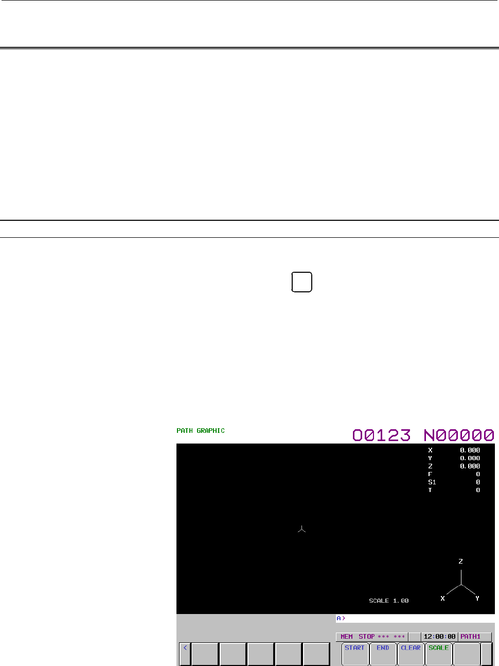
- Tool path graphic screen
The tool path graphic screen consists of three major areas:
- Graphic area for drawing a tool path
- Area for displaying machining information such as tool position
information
- Area for displaying a graphic coordinate system
Fig. 13.1 (a) Tool path graphic screen (M series)
Contents Summary of 30i/300i/300is-MA, 31i/310i/310is-MA & A5, 32i/320i/320is-MA Common to Lathe/Machining Center Users manual
- Page 1FANUC Series 30*/300*/300*s-MODEL A FANUC Series 31*/310*/310*s-MODEL A5 FANUC Series 31*/310*/310*s-MODEL A FANUC Series 32*/320*/320*s-MODEL A Common to Lathe System/Machining Center System USER’S MANUAL B-63944EN/02
- Page 2• No part of this manual may be reproduced in any form. • All specifications and designs are subject to change without notice. The export of this product is subject to the authorization of the government of the country from where the product is exported. In this manual we have tried as much as possi
- Page 3B-63944EN/02 SAFETY PRECAUTIONS SAFETY PRECAUTIONS This section describes the safety precautions related to the use of CNC units. It is essential that these precautions be observed by users to ensure the safe operation of machines equipped with a CNC unit (all descriptions in this section assume thi
- Page 4SAFETY PRECAUTIONS B-63944EN/02 1.1 DEFINITION OF WARNING, CAUTION, AND NOTE This manual includes safety precautions for protecting the user and preventing damage to the machine. Precautions are classified into Warning and Caution according to their bearing on safety. Also, supplementary information
- Page 5B-63944EN/02 SAFETY PRECAUTIONS 1.2 GENERAL WARNINGS AND CAUTIONS WARNING 1 Never attempt to machine a workpiece without first checking the operation of the machine. Before starting a production run, ensure that the machine is operating correctly by performing a trial run using, for example, the sin
- Page 6SAFETY PRECAUTIONS B-63944EN/02 WARNING 5 The parameters for the CNC and PMC are factory-set. Usually, there is not need to change them. When, however, there is not alternative other than to change a parameter, ensure that you fully understand the function of the parameter before making any change.
- Page 7B-63944EN/02 SAFETY PRECAUTIONS NOTE Programs, parameters, and macro variables are stored in nonvolatile memory in the CNC unit. Usually, they are retained even if the power is turned off. Such data may be deleted inadvertently, however, or it may prove necessary to delete all data from nonvolatile
- Page 8SAFETY PRECAUTIONS B-63944EN/02 1.3 WARNINGS AND CAUTIONS RELATED TO PROGRAMMING This section covers the major safety precautions related to programming. Before attempting to perform programming, read the supplied User’s Manual carefully such that you are fully familiar with their contents. WARNING
- Page 9B-63944EN/02 SAFETY PRECAUTIONS WARNING 5 Constant surface speed control When an axis subject to constant surface speed control approaches the origin of the workpiece coordinate system, the spindle speed may become excessively high. Therefore, it is necessary to specify a maximum allowable speed. Sp
- Page 10SAFETY PRECAUTIONS B-63944EN/02 WARNING 11 Programmable mirror image Note that programmed operations vary considerably when a programmable mirror image is enabled. 12 Compensation function If a command based on the machine coordinate system or a reference position return command is issued in compens
- Page 11B-63944EN/02 SAFETY PRECAUTIONS 1.4 WARNINGS AND CAUTIONS RELATED TO HANDLING This section presents safety precautions related to the handling of machine tools. Before attempting to operate your machine, read the supplied User’s Manual carefully, such that you are fully familiar with their contents.
- Page 12SAFETY PRECAUTIONS B-63944EN/02 WARNING 5 Disabled override If override is disabled (according to the specification in a macro variable) during threading, rigid tapping, or other tapping, the speed cannot be predicted, possibly damaging the tool, the machine itself, the workpiece, or causing injury
- Page 13B-63944EN/02 SAFETY PRECAUTIONS WARNING 10 Manual intervention If manual intervention is performed during programmed operation of the machine, the tool path may vary when the machine is restarted. Before restarting the machine after manual intervention, therefore, confirm the settings of the manual
- Page 14SAFETY PRECAUTIONS B-63944EN/02 1.5 WARNINGS RELATED TO DAILY MAINTENANCE WARNING 1 Memory backup battery replacement When replacing the memory backup batteries, keep the power to the machine (CNC) turned on, and apply an emergency stop to the machine. Because this work is performed with the power o
- Page 15B-63944EN/02 SAFETY PRECAUTIONS WARNING 2 Absolute pulse coder battery replacement When replacing the memory backup batteries, keep the power to the machine (CNC) turned on, and apply an emergency stop to the machine. Because this work is performed with the power on and the cabinet open, only those
- Page 16SAFETY PRECAUTIONS B-63944EN/02 WARNING 3 Fuse replacement Before replacing a blown fuse, however, it is necessary to locate and remove the cause of the blown fuse. For this reason, only those personnel who have received approved safety and maintenance training may perform this work. When replacing
- Page 17B-63944EN/02 TABLE OF CONTENTS TABLE OF CONTENTS SAFETY PRECAUTIONS............................................................................s-1 I. GENERAL 1 GENERAL .............................................................................................................. 3 1.1 NOTES ON READIN
- Page 18TABLE OF CONTENTS B-63944EN/02 4.2 SINGLE DIRECTION POSITIONING (G60) ................................................ 50 4.3 LINEAR INTERPOLATION (G01)................................................................ 53 4.4 CIRCULAR INTERPOLATION (G02, G03)...........................................
- Page 19B-63944EN/02 TABLE OF CONTENTS 7.2 WORKPIECE COORDINATE SYSTEM .................................................... 170 7.2.1 Setting a Workpiece Coordinate System..............................................................170 7.2.2 Selecting a Workpiece Coordinate System .........................
- Page 20TABLE OF CONTENTS B-63944EN/02 10.3.7 Total Life Time Display for Tools of The Same Type.........................................251 10.4 TOOL MANAGEMENT FUNCTION OVERSIZE TOOLS SUPPORT ........ 252 11 AUXILIARY FUNCTION ...................................................................... 254 11.1
- Page 21B-63944EN/02 TABLE OF CONTENTS 15.4 TOOL AXIS DIRECTION TOOL LENGTH COMPENSATION ................... 337 15.4.1 Control Point Compensation of Tool Length Compensation Along Tool Axis ...343 16 CUSTOM MACRO............................................................................... 348 16.1 VARIAB
- Page 22TABLE OF CONTENTS B-63944EN/02 17 REAL-TIME CUSTOM MACRO .......................................................... 489 17.1 TYPES OF REAL TIME MACRO COMMANDS......................................... 493 17.1.1 Modal Real Time Macro Command / One-shot Real Time Macro Command.....493 17.2 VARIABLES..
- Page 23B-63944EN/02 TABLE OF CONTENTS 20.1.6 Methods of Alarm Recovery by Synchronous Error Check.................................588 20.1.7 Axis Synchronous Control Torque Difference Alarm..........................................590 20.2 POLYGON TURNING (G50.2, G51.2).....................................
- Page 24TABLE OF CONTENTS B-63944EN/02 22 MUITI-PATH CONTROL FUNCTION.................................................. 801 22.1 OVERVIEW ............................................................................................... 802 22.2 WAITING FUNCTION FOR PATHS ......................................
- Page 25B-63944EN/02 TABLE OF CONTENTS 2.3.3 Soft Keys ..............................................................................................................851 2.3.4 Key Input and Input Buffer ..................................................................................861 2.3.5 Warning Messag
- Page 26TABLE OF CONTENTS B-63944EN/02 4 AUTOMATIC OPERATION ................................................................. 925 4.1 MEMORY OPERATION ............................................................................ 926 4.2 MDI OPERATION .........................................................
- Page 27B-63944EN/02 TABLE OF CONTENTS 6.5.2.4 Confirmation of the start from a middle block .............................................. 1007 6.5.2.5 Data range check ........................................................................................... 1008 6.5.2.6 Maximum incremental value check .
- Page 28TABLE OF CONTENTS B-63944EN/02 8.1.9 Inputting and Outputting Tool Management Data .............................................1054 8.1.9.1 Inputting tool management data .................................................................... 1054 8.1.9.2 Outputting tool management data...............
- Page 29B-63944EN/02 TABLE OF CONTENTS 10.2.4 Altering a Word..................................................................................................1102 10.2.5 Deleting a Word .................................................................................................1103 10.3 DELETING BLOCK
- Page 30TABLE OF CONTENTS B-63944EN/02 11.8 DELETING A FILE................................................................................... 1145 11.9 CHANGING FILE ATTRIBUTES.............................................................. 1146 11.10 SELECTING A MAIN PROGRAM.................................
- Page 31B-63944EN/02 TABLE OF CONTENTS 12.3.9.3 Each tool data screen ..................................................................................... 1230 12.3.9.4 Displaying the total life of tools of the same type ......................................... 1233 12.3.9.5 Tool geometry data screen.....
- Page 32TABLE OF CONTENTS B-63944EN/02 12.6.2 Displaying the Status and Warning for Data Setting or Input/Output Operation ............................................................................................................1307 13 GRAPHIC FUNCTION.....................................................
- Page 33B-63944EN/02 TABLE OF CONTENTS H.1.2 List of Functions of PC Tool..............................................................................1647 H.1.3 Explanation Of Operations.................................................................................1648 H.2 NAMING RULES ..................
- Page 34
- Page 35I. GENERA
- Page 36
- Page 37B-63944EN/02 GENERAL 1.GENERAL 1 GENERAL This manual consists of the following parts: About this manual I. GENERAL Describes chapter organization, applicable models, related manuals, and notes for reading this manual. II. PROGRAMMING Describes each function: Format used to program functions in the N
- Page 381.GENERAL GENERAL B-63944EN/02 Applicable models This manual describes the models indicated in the table below. In the text, the abbreviations indicated below may be used. Model name Abbreviation FANUC Series 30i-MODEL A 30i –A Series 30i FANUC Series 300i-MODEL A 300i–A Series 300i FANUC Series 300
- Page 39B-63944EN/02 GENERAL 1.GENERAL Special symbols This manual uses the following symbols: - M Indicates a description that is valid only for the machine center system set as system control type (in parameter No. 0983). In a general description of the method of machining, a machining center system opera
- Page 401.GENERAL GENERAL B-63944EN/02 Related manuals of Series 30i/300i/300is- MODEL A Series 31i/310i/310is- MODEL A Series 31i/310i/310is- MODEL A5 Series 32i/320i/320is- MODEL A The following table lists the manuals related to Series 30i/300i /300is- A, Series 31i/310i /310is-A, Series 31i/310i /310is-
- Page 41B-63944EN/02 GENERAL 1.GENERAL Related manuals of SERVO MOTOR αis/αi/βis/βi series The following table lists the manuals related to SERVO MOTOR αis/αi/βis/βi series Table 2 Related manuals Specification Manual name number FANUC AC SERVO MOTOR αis series FANUC AC SERVO MOTOR αi series B-65262EN DESCR
- Page 421.GENERAL GENERAL B-63944EN/02 1.1 NOTES ON READING THIS MANUAL CAUTION 1 The function of an CNC machine tool system depends not only on the CNC, but on the combination of the machine tool, its magnetic cabinet, the servo system, the CNC, the operator's panels, etc. It is too difficult to describe t
- Page 43II. PROGRAMMIN
- Page 44
- Page 45B-63944EN/02 PROGRAMMING 1.GENERAL 1 GENERAL - 11 -
- Page 461.GENERAL PROGRAMMING B-63944EN/02 1.1 TOOL MOVEMENT ALONG WORKPIECE PARTS FIGURE- INTERPOLATION The tool moves along straight lines and arcs constituting the workpiece parts figure (See II-4). Explanation The function of moving the tool along straight lines and arcs is called the interpolation. - T
- Page 47B-63944EN/02 PROGRAMMING 1.GENERAL - Tool movement along an arc • For milling machining Program G03 X_ Y_ R_ ; Tool Workpiece • For lathe cutting X Program G02 X_ Z_ R_ ; or G03 X_ Z_ R_ ; Workpiece Z Fig. 1.1 (b) Tool movement along an arc The term interpolation refers to an operation in which the
- Page 481.GENERAL PROGRAMMING B-63944EN/02 1.2 FEED-FEED FUNCTION Movement of the tool at a specified speed for cutting a workpiece is called the feed. • For milling machining mm/min Tool F Workpiece Table • For lathe cutting mm/min Tool F Workpiece Chuck Fig. 1.2 (a) Feed function Feedrates can be specifie
- Page 49B-63944EN/02 PROGRAMMING 1.GENERAL 1.3 PART DRAWING AND TOOL MOVEMENT 1.3.1 Reference Position (Machine-specific Position) A CNC machine tool is provided with a fixed position. Normally, tool change and programming of absolute zero point as described later are performed at this position. This positi
- Page 501.GENERAL PROGRAMMING B-63944EN/02 1.3.2 Coordinate System on Part Drawing and Coordinate System Specified by CNC - Coordinate System • For milling machining Z Z Y Program Y X X Coordinate system Part drawing CNC Tool Command Tool Z Y Workpiece X Machine tool • For lathe cutting X X Program Z Z Coor
- Page 51B-63944EN/02 PROGRAMMING 1.GENERAL Explanation - Coordinate system The following two coordinate systems are specified at different locations: (See II-7) 1 Coordinate system on part drawing The coordinate system is written on the part drawing. As the program data, the coordinate values on this coordi
- Page 521.GENERAL PROGRAMMING B-63944EN/02 The positional relation between these two coordinate systems is determined when a workpiece is set on the table. • For milling machining Coordinate system on part drawing estab lished on the workpiece Coordinate system specified by the CNC established on the table
- Page 53B-63944EN/02 PROGRAMMING 1.GENERAL - Methods of setting the two coordinate systems in the same position M To set the two coordinate systems at the same position, simple methods shall be used according to workpiece shape, the number of machinings. 1. Using a standard plane and point of the workpiece.
- Page 541.GENERAL PROGRAMMING B-63944EN/02 T The following method is usually used to define two coordinate systems at the same location. 1 When coordinate zero point is set at chuck face - Coordinates and X dimensions on part drawing Workpiece Z 60 40 40 150 - Coordinate system on lathe as specified by CNC
- Page 55B-63944EN/02 PROGRAMMING 1.GENERAL 2. When coordinate zero point is set at workpiece end face. - Coordinates and X dimensions on part drawing 60 Workpiece 30 Z 30 80 100 - Coordinate system on lathe as specified by CNC Chuck X Workpiece Z Program origin When the coordinate system on the part drawing
- Page 561.GENERAL PROGRAMMING B-63944EN/02 1.3.3 How to Indicate Command Dimensions for Moving the Tool (Absolute, Incremental Commands) Explanation Command for moving the tool can be indicated by absolute command or incremental command (See II-8.1). - Absolute command The tool moves to a point at "the dist
- Page 57B-63944EN/02 PROGRAMMING 1.GENERAL - Incremental command Specify the distance from the previous tool position to the next tool position. • For milling machining Z Tool A X=40.0 Y Z=-10.0 X B Y-30.0 Command specifying movement from G91 X40.0 Y-30.0 Z-10.0 ; point A to point B Distance and direction f
- Page 581.GENERAL PROGRAMMING B-63944EN/02 - Diameter programming / radius programming Dimensions of the X axis can be set in diameter or in radius. Diameter programming or radius programming is employed independently in each machine. 1. Diameter programming In diameter programming, specify the diameter val
- Page 59B-63944EN/02 PROGRAMMING 1.GENERAL 1.4 CUTTING SPEED - SPINDLE FUNCTION The speed of the tool with respect to the workpiece when the workpiece is cut is called the cutting speed. As for the CNC, the cutting speed can be specified by the spindle speed in min-1 unit. • For milling machining Tool Tool
- Page 601.GENERAL PROGRAMMING B-63944EN/02 1.5 SELECTION OF TOOL USED FOR VARIOUS MACHINING - TOOL FUNCTION Overview For each of various types of machining (such as drilling, tapping, boring, and milling for milling machining, or rough machining, semifinish machining, finish machining, threading, and groovi
- Page 61B-63944EN/02 PROGRAMMING 1.GENERAL 1.6 COMMAND FOR MACHINE OPERATIONS - AUXILIARY FUNCTION When a workpiece is actually machined with a tool, the spindle is rotated, coolant is supplied, and the chuck is opened/closed. So, control needs to be exercised on the spindle motor of the machine, coolant va
- Page 621.GENERAL PROGRAMMING B-63944EN/02 1.7 PROGRAM CONFIGURATION A group of commands given to the CNC for operating the machine is called the program. By specifying the commands, the tool is moved along a straight line or an arc, or the spindle motor is turned on and off. In the program, specify the com
- Page 63B-63944EN/02 PROGRAMMING 1.GENERAL Explanation The block and the program have the following configurations. - Block 1 block Nxxxxx Gxx Xxxx.x Yxxx.x Mxx Sxx Txx ; Sequence Preparatory Dimension word Auxiliary Spindle Tool number function function function function End of block Fig. 1.7 (b) Block con
- Page 641.GENERAL PROGRAMMING B-63944EN/02 - Main program and subprogram When machining of the same pattern appears at many portions of a program, a program for the pattern is created. This is called the subprogram. On the other hand, the original program is called the main program. When a subprogram execut
- Page 65B-63944EN/02 PROGRAMMING 1.GENERAL 1.8 TOOL MOVEMENT RANGE - STROKE Limit switches are installed at the ends of each axis on the machine to prevent tools from moving beyond the ends. The range in which tools can move is called the stroke. Machine zero point Motor Limit switch Stroke area Besides str
- Page 661.GENERAL PROGRAMMING B-63944EN/02 Motor Limit switch Machine zero point Specify these distances. Tools cannot enter this area. The area is specified by data in memory or a program. - 32 -
- Page 67B-63944EN/02 PROGRAMMING 2.CONTROLLED AXES 2 CONTROLLED AXES - 33 -
- Page 682.CONTROLLED AXES PROGRAMMING B-63944EN/02 2.1 NUMBER OF CONTROLLED AXES Explanation The number of controlled axes used with this NC system depends on the model and system control type as indicated below. Series 30i-A Series 31i-A5 Series 31i-A Series 32i-A Series 300i-A Series 310i-A5 Series 310i-A
- Page 69B-63944EN/02 PROGRAMMING 2.CONTROLLED AXES 2.2 NAMES OF AXES Explanation The move axes of machine tools are assigned names. These names are referred to as addresses or axis names. Axis names are determined according to the machine tool. The naming rules comply with standards such as the ISO standard
- Page 702.CONTROLLED AXES PROGRAMMING B-63944EN/02 2.3 INCREMENT SYSTEM Explanation The increment system consists of the least input increment (for input) and least command increment (for output). The least input increment is the least increment for programming the travel distance. The least command increme
- Page 71B-63944EN/02 PROGRAMMING 2.CONTROLLED AXES 2.4 MAXIMUM STROKE Explanation The maximum stroke controlled by this CNC is shown in the table below: Maximum stroke = Least command increment × 99999999 (999999999 for IS-D and IS-E) Commands that exceed the maximum stroke are not permitted. Table 2.4 (a)
- Page 723.PREPARATORY FUNCTION (G FUNCTION) PROGRAMMING B-63944EN/02 3 PREPARATORY FUNCTION (G FUNCTION) A number following address G determines the meaning of the command for the concerned block. G codes are divided into the following two types. Type Meaning The G code is effective only in the block in whi
- Page 73B-63944EN/02 PROGRAMMING3.PREPARATORY FUNCTION (G FUNCTION) Explanation 1. When the clear state (parameter CLR (No. 3402#6)) is set at power-up or reset, the modal G codes are placed in the states described below. (1) The modal G codes are placed in the states marked with as indicated in Table. (2)
- Page 743.PREPARATORY FUNCTION (G FUNCTION) PROGRAMMING B-63944EN/02 3.1 G CODE LIST IN THE MACHINING CENTER SYSTEM M Table 3.1 (a) G code list G code Group Function G00 Positioning (rapid traverse) G01 Linear interpolation (cutting feed) G02 Circular interpolation CW or helical interpolation CW G03 01 Circ
- Page 75B-63944EN/02 PROGRAMMING3.PREPARATORY FUNCTION (G FUNCTION) Table 3.1 (a) G code list G code Group Function G37 Automatic tool length measurement G38 00 Cutter or tool nose radius compensation : preserve vector G39 Cutter or tool nose radius compensation : corner circular interpolation Cutter or too
- Page 763.PREPARATORY FUNCTION (G FUNCTION) PROGRAMMING B-63944EN/02 Table 3.1 (a) G code list G code Group Function G61 Exact stop mode G62 Automatic corner override 15 G63 Tapping mode G64 Cutting mode G65 00 Macro call G66 Macro modal call A G66.1 12 Macro modal call B G67 Macro modal call A/B cancel G68
- Page 77B-63944EN/02 PROGRAMMING3.PREPARATORY FUNCTION (G FUNCTION) 3.2 G CODE LIST IN THE LATHE SYSTEM T Table 3.2 (a) G code list G code system Group Function A B C G00 G00 G00 Positioning (Rapid traverse) G01 G01 G01 Linear interpolation (Cutting feed) G02 G02 G02 Circular interpolation CW or helical int
- Page 783.PREPARATORY FUNCTION (G FUNCTION) PROGRAMMING B-63944EN/02 Table 3.2 (a) G code list G code system Group Function A B C G27 G27 G27 Reference position return check G28 G28 G28 Return to reference position G29 G29 G29 Movement from reference position G30 G30 G30 00 2nd, 3rd and 4th reference positi
- Page 79B-63944EN/02 PROGRAMMING3.PREPARATORY FUNCTION (G FUNCTION) Table 3.2 (a) G code list G code system Group Function A B C G50 G92 G92 Coordinate system setting or max. spindle speed clamp 00 G50.3 G92.1 G92.1 Workpiece coordinate system preset - G50 G50 Scaling cancel 18 - G51 G51 Scaling G50.1 G50.1
- Page 803.PREPARATORY FUNCTION (G FUNCTION) PROGRAMMING B-63944EN/02 Table 3.2 (a) G code list G code system Group Function A B C G80 G80 G80 10 Canned cycle cancel for drilling G80.5 G80.5 G80.5 27 Electronic gear box 2 pair: synchronization cancellation G80.8 G80.8 G80.8 28 Electronic gear box: synchroniz
- Page 81B-63944EN/02 PROGRAMMING 4.INTERPOLATION FUNCTIONS 4 INTERPOLATION FUNCTIONS Interpolation functions specify the way to make an axis movement (in other words, a movement of the tool with respect to the workpiece or table). - 47 -
- Page 824.INTERPOLATION FUNCTIONS PROGRAMMING B-63944EN/02 4.1 POSITIONING (G00) The G00 command moves a tool to the position in the workpiece system specified with an absolute or an incremental command at a rapid traverse rate. In the absolute command, coordinate value of the end point is programmed. In th
- Page 83B-63944EN/02 PROGRAMMING 4.INTERPOLATION FUNCTIONS Limitation The rapid traverse rate cannot be specified in the address F. Even if linear interpolation type positioning is specified, nonlinear type interpolation positioning is used in the following cases. Therefore, be careful to ensure that the to
- Page 844.INTERPOLATION FUNCTIONS PROGRAMMING B-63944EN/02 4.2 SINGLE DIRECTION POSITIONING (G60) For accurate positioning without play of the machine (backlash), final positioning from one direction is available. Overrun Start point Start point End point Temporary stop Format G60 IP_ ; IP_ : For an absolut
- Page 85B-63944EN/02 PROGRAMMING 4.INTERPOLATION FUNCTIONS - Overview of operation • In the case of positioning of non-linear interpolation type (bit 1 (LRP) of parameter No. 1401 = 0) As shown below, single direction positioning is performed independently along each axis. X Overrun distance in the Z-axis d
- Page 864.INTERPOLATION FUNCTIONS PROGRAMMING B-63944EN/02 non-buffering M code. Then, switch mirror image when there is no look-ahead block. • In the cylindrical interpolation mode (G07.1), single direction positioning cannot be used. • In the polar coordinate interpolation mode (G12.1), single direction p
- Page 87B-63944EN/02 PROGRAMMING 4.INTERPOLATION FUNCTIONS 4.3 LINEAR INTERPOLATION (G01) Tools can move along a line. Format G01 IP_ F_ ; IP_ : For an absolute command, the coordinates of an end point, and for an incremental command, the distance the tool moves. F_ : Speed of tool feed (Feedrate) Explanati
- Page 884.INTERPOLATION FUNCTIONS PROGRAMMING B-63944EN/02 A calculation example is as follows. G91 G01 X20.0B40.0 F300.0 ; This changes the unit of the C axis from 40.0 deg to 40mm with metric input. The time required for distribution is calculated as follows: 20 2 + 40 2 0.14907(mm) 300 The feedrate for t
- Page 89B-63944EN/02 PROGRAMMING 4.INTERPOLATION FUNCTIONS - Feedrate for the rotary axis G91G01C-90.0 F300.0 ;Feed rate of 300deg/min (Start point) 90° (End point) Feedrate is 300 deg/min - 55 -
- Page 904.INTERPOLATION FUNCTIONS PROGRAMMING B-63944EN/02 4.4 CIRCULAR INTERPOLATION (G02, G03) The command below will move a tool along a circular arc. Format Arc in the XpYp plane G 02 I _ J _ G17 Xp _ Yp _ F _; G 03 R _ Arc in the ZpXp plane G 02 I _ K _ G18 Zp _ Xp _ F _; G 03
- Page 91B-63944EN/02 PROGRAMMING 4.INTERPOLATION FUNCTIONS Explanation - Direction of the circular interpolation "Clockwise"(G02) and "counterclockwise"(G03) on the XpYp plane (ZpXp plane or YpZp plane) are defined when the XpYp plane is viewed in the positive-to-negative direction of the Zp axis (Yp axis o
- Page 924.INTERPOLATION FUNCTIONS PROGRAMMING B-63944EN/02 - Arc radius The distance between an arc and the center of a circle that contains the arc can be specified using the radius, R, of the circle instead of I, J, and K. In this case, one arc is less than 180°, and the other is more than 180° are consid
- Page 93B-63944EN/02 PROGRAMMING 4.INTERPOLATION FUNCTIONS Limitation - Simultaneously specifying R with I, J, and K If I, J, K, and R addresses are specified simultaneously, the arc specified by address R takes precedence and the other are ignored. - Specifying an axis that is not contained in the specifie
- Page 944.INTERPOLATION FUNCTIONS PROGRAMMING B-63944EN/02 Example M Y axis 100 50 60 60 40 X axis 0 90 120 140 200 The above tool path can be programmed as follows ; (1) In absolute programming G92X200.0 Y40.0 Z0 ; G90 G03 X140.0 Y100.0R60.0 F300.; G02 X120.0 Y60.0R50.0 ; or G92X200.0 Y40.0Z0 ; G90 G03 X14
- Page 95B-63944EN/02 PROGRAMMING 4.INTERPOLATION FUNCTIONS T - Command of circular interpolation X, Z G02X_Z_I_K_F_; G03X_Z_I_K_F_; G02X_Z_R_F_; Center of arc Center of arc End point End point End point X-axis X-axis X-axis I R (Diameter (Diameter (Diameter programming) programming) programming) Start point
- Page 964.INTERPOLATION FUNCTIONS PROGRAMMING B-63944EN/02 4.5 HELICAL INTERPOLATION (G02, G03) Helical interpolation which moved helically is enabled by specifying up to two other axes which move synchronously with the circular interpolation by circular commands. Format Arc of XpYp plane G02 I_J_ G17 Xp_Yp
- Page 97B-63944EN/02 PROGRAMMING 4.INTERPOLATION FUNCTIONS Z Tool path X Y The feedrate along the circumference of two circular interpolated axes is the specified feedrate. If HTG is set to 1, specify a feedrate along the tool path about the linear axis. Therefore, the tangential velocity of the arc is expr
- Page 984.INTERPOLATION FUNCTIONS PROGRAMMING B-63944EN/02 4.6 HELICAL INTERPOLATION B (G02, G03) The helical interpolation B function differs from the helical interpolation function just in that circular interpolation and a movement on four axes outside the specified plane can be simultaneously performed.
- Page 99B-63944EN/02 PROGRAMMING 4.INTERPOLATION FUNCTIONS 4.7 SPIRAL INTERPOLATION, CONICAL INTERPOLATION (G02, G03) Spiral interpolation is enabled by specifying the circular interpolation command together with a desired number of revolutions or a desired increment (decrement) for the radius per revolutio
- Page 1004.INTERPOLATION FUNCTIONS PROGRAMMING B-63944EN/02 - Conical interpolation XpYp plane G02 G17 X_Y_I_J_Z_Q_L_F_; G03 ZpXp plane G02 G18 Z_X_K_I_Y_Q_L_F_; G03 YpZp plane G02 G19 Y_Z_J_K_X_Q_L_F_; G03 X, Y, Z : Coordinates of the end point L : Number of revolutions (positive value without a decimal poi
- Page 101B-63944EN/02 PROGRAMMING 4.INTERPOLATION FUNCTIONS Explanation - Function of spiral interpolation Spiral interpolation in the XY plane is defined as follows: (X − X 0 ) 2 + (Y − Y0 ) 2 = (R + Q' ) 2 X0 : X coordinate of the center Y0 : Y coordinate of the center R : Radius at the beginning of spiral
- Page 1024.INTERPOLATION FUNCTIONS PROGRAMMING B-63944EN/02 - Difference between end points If the difference between the programmed end point and the calculated end point of a spiral exceeds a value specified in parameter No. 3471 about any axis of a selected plane, an alarm PS5123 will be issued. If the di
- Page 103B-63944EN/02 PROGRAMMING 4.INTERPOLATION FUNCTIONS - Cutter compensation M The spiral or conical interpolation command can be programmed in cutter compensation mode. This compensation is performed in the same way as described in "When it is exceptional" in "Tool Movement in Offset Mode" section. A v
- Page 1044.INTERPOLATION FUNCTIONS PROGRAMMING B-63944EN/02 - Deceleration by acceleration During spiral interpolation, the function of deceleration by acceleration is enabled. The feedrate may decrease as the tool approaches the center of the spiral. - Dry run When the dry run signal is inverted from 0 to 1
- Page 105B-63944EN/02 PROGRAMMING 4.INTERPOLATION FUNCTIONS Example - Spiral interpolation The path indicated below is programmed with absolute and incremental values as follows: 20. 20. 120 Y axis 100 80 60 40 20 -120 -100 -80 -60 -40 –20 20 40 60 80 100 120 X axis -20 -40 -60 -80 -100 -120 This sample path
- Page 1064.INTERPOLATION FUNCTIONS PROGRAMMING B-63944EN/02 - Conical interpolation The sample path shown below is programmed with absolute and incremental values as follows: +Z 25.0 25.0 (0,-37.5,62.5) 25.0 25.0 +Y 100.0 -100.0 +X This sample path has the following values: • Start point : (0, 100.0, 0) • En
- Page 107B-63944EN/02 PROGRAMMING 4.INTERPOLATION FUNCTIONS 4.8 POLAR COORDINATE INTERPOLATION (G12.1, G13.1) Overview Polar coordinate interpolation is a function that exercises contour control in converting a command programmed in a Cartesian coordinate system to the movement of a linear axis (movement of
- Page 1084.INTERPOLATION FUNCTIONS PROGRAMMING B-63944EN/02 - Polar coordinate interpolation plane G12.1 starts the polar coordinate interpolation mode and selects a polar coordinate interpolation plane (Fig. 4.8 (a)). Polar coordinate interpolation is performed on this plane. Rotary axis (virtual axis) (uni
- Page 109B-63944EN/02 PROGRAMMING 4.INTERPOLATION FUNCTIONS Example) When a value on the X-axis (linear axis) is input in millimeters G12.1; G01 X10. F1000.;..... A 10-mm movement is made on the Cartesian coordinate system. C20.; ......................... A 20-mm movement is made on the Cartesian coordinate
- Page 1104.INTERPOLATION FUNCTIONS PROGRAMMING B-63944EN/02 - Movement along axes not in the polar coordinate interpolation plane in the polar coordinate interpolation mode The tool moves along such axes normally, independent of polar coordinate interpolation. - Current position display in the polar coordina
- Page 111B-63944EN/02 PROGRAMMING 4.INTERPOLATION FUNCTIONS - Shifting the coordinate system in polar coordinate interpolation In the polar coordinate interpolation mode, the workpiece coordinate system can be shifted. The current position display function shows the position viewed from the workpiece coordin
- Page 1124.INTERPOLATION FUNCTIONS PROGRAMMING B-63944EN/02 - Program restart For a block in the G12.1 mode, the program and the block cannot be restarted. - Cutting feedrate for the rotary axis Polar coordinate interpolation converts the tool movement for a figure programmed in a Cartesian coordinate system
- Page 113B-63944EN/02 PROGRAMMING 4.INTERPOLATION FUNCTIONS - Automatic speed control for polar coordinate interpolation If the velocity component of the rotary axis exceeds the maximum cutting feedrate in the polar coordinate interpolation mode, the speed is automatically controlled. - Automatic override If
- Page 1144.INTERPOLATION FUNCTIONS PROGRAMMING B-63944EN/02 NOTE 1 While the automatic speed clamp function is working, the machine lock or interlock function may not be enabled immediately. 2 If a feed hold stop is made while the automatic speed clamp function is working, the automatic operation halt signal
- Page 115B-63944EN/02 PROGRAMMING 4.INTERPOLATION FUNCTIONS Example Sample program for polar coordinate interpolation in a Cartesian coordinate system consisting of the X-axis (a linear axis) and a hypothetical axis Hypothetical axis C axis Path after cutter compensation Program path N204 N203 N205 N202 N201
- Page 1164.INTERPOLATION FUNCTIONS PROGRAMMING B-63944EN/02 4.9 CYLINDRICAL INTERPOLATION (G07.1) In cylindrical interpolation, the amount of movement of a rotary axis specified by angle is converted to the amount of movement on the circumference to allow linear interpolation and circular interpolation with
- Page 117B-63944EN/02 PROGRAMMING 4.INTERPOLATION FUNCTIONS - Circular interpolation (G02,G03) Circular interpolation can be performed between the rotary axis set for cylindrical interpolation and another linear axis. Radius R is used in commands in the same way as described. The unit for a radius is not deg
- Page 1184.INTERPOLATION FUNCTIONS PROGRAMMING B-63944EN/02 Limitation - Arc radius specification in the circular interpolation In the cylindrical interpolation mode, an arc radius cannot be specified with word address I, J, or K. - Positioning In the cylindrical interpolation mode, positioning operations (i
- Page 119B-63944EN/02 PROGRAMMING 4.INTERPOLATION FUNCTIONS M - Coordinate system setting In the cylindrical interpolation mode, a workpiece coordinate system (G92, G54 to G59) or local coordinate system (G52) cannot be specified. - Tool offset A tool offset must be specified before the cylindrical interpola
- Page 1204.INTERPOLATION FUNCTIONS PROGRAMMING B-63944EN/02 Example C Example of a Cylindrical Interpolation O0001 (CYLINDRICAL INTERPOLATION ); Program N01 G00 G90 Z100.0 C0 ; N02 G01 G91 G18 Z0 C0 ; N03 G07.1 C57299 ;* N04 G90 G01 G42 Z120.0 D01 F250 ; Z R N05 C30.0 ; N06 G03 Z90.0 C60.0 R30.0 ; N07 G01 Z7
- Page 121B-63944EN/02 PROGRAMMING 4.INTERPOLATION FUNCTIONS 4.10 CUTTING POINT INTERPOLATION FOR CYLINDRICAL INTERPOLATION (G07.1) The conventional cylindrical interpolation function controls the tool center so that the tool axis always moves along a specified path on the cylindrical surface, towards the rot
- Page 1224.INTERPOLATION FUNCTIONS PROGRAMMING B-63944EN/02 - Cutting point compensation (1) Cutting point compensation between blocks As shown in Fig. 4.10(b), cutting point compensation is achieved by moving between blocks N1 and N2. (a) Let C1 and C2 be the heads of the vectors normal to N1 and N2 from S1
- Page 123B-63944EN/02 PROGRAMMING 4.INTERPOLATION FUNCTIONS ∆V : Cutting point compensation value (∆V2 - ∆V1) for movement of ∆L ∆V1 : C-axis component of the vector normal to N1 from the tool center of the start point of ∆L ∆V2 : C-axis component of the vector normal to N1 from the tool center of the end po
- Page 1244.INTERPOLATION FUNCTIONS PROGRAMMING B-63944EN/02 (b) When parameter CYS (No.19530#6) is set to 0 Cutting point compensation is not performed between blocks N1 and N2. Whether to apply cutting point compensation between block N2 and N3 is determined by taking the cutting point compensation value be
- Page 125B-63944EN/02 PROGRAMMING 4.INTERPOLATION FUNCTIONS (d) When, as shown in Fig. 4.10(g), the diameter of an arc (R in the figure) is less than the value set in parameter No. 19535, cutting point compensation is not applied simultaneously with circular interpolation V :Cutting point compensation betwee
- Page 1264.INTERPOLATION FUNCTIONS PROGRAMMING B-63944EN/02 (1) When the normal direction changes between blocks N1 and N2, cutting point compensation is also performed between blocks N1 and N2. As shown in Fig. 4.10 (i), cutting point compensation described in (1) in "Cutting point compensation" is performe
- Page 127B-63944EN/02 PROGRAMMING 4.INTERPOLATION FUNCTIONS (3) When a specified block is executed while the normal direction control axis is held in the normal direction set at the end point of the previous block, cutting point compensation is not performed, and cutting point compensation applied in the pre
- Page 1284.INTERPOLATION FUNCTIONS PROGRAMMING B-63944EN/02 Fc : Speed component of cylindrical interpolation rotation axis before cutting point compensation Vcs: Rotation axis component of a tool contact point vector (Vs in the figure) at the start point at a point in time Vce: Rotation axis component of to
- Page 129B-63944EN/02 PROGRAMMING 4.INTERPOLATION FUNCTIONS - Parameter To enable this function, set bit 5 (CYA) of parameter No. 19530 to 1. Limitation - Overcutting during inner corner cutting Theoretically, when the inner area of a corner is cut using linear interpolation as shown in Fig. 4.10(m), this fu
- Page 1304.INTERPOLATION FUNCTIONS PROGRAMMING B-63944EN/02 Example - Example of cutting point interpolation for cylindrical interpolation The sample program below indicates the positional relationships between a workpiece and tool. O0001 (CYLINDRICAL INTERPOLATION1) ; N01 G00 G90 Z100.0 C0 ; N02 G01 G91 G19
- Page 131B-63944EN/02 PROGRAMMING 4.INTERPOLATION FUNCTIONS Positional relationship between the Positional relationship between the workpiece and tool of (1) workpiece and tool of (2) Rotation Rotation Workpiece 0° 0° 20° Cutting surface Tool Y-axis Y-axis Tool center Positional relationship between the Posi
- Page 1324.INTERPOLATION FUNCTIONS PROGRAMMING B-63944EN/02 - Example of specifying cutting point interpolation for cylindrical interpolation and normal direction control at the same time Cutter compensation No.01 is 30 mm. O0002(CYLINDRICAL INTERPOLATION2) ; N01 G00 G90 X100.0 A0 ; N02 G01 G91 G17 X0 A0 ; N
- Page 133B-63944EN/02 PROGRAMMING 4.INTERPOLATION FUNCTIONS 4.11 EXPONENTIAL INTERPOLATION (G02.3, G03.3) Exponential interpolation exponentially changes the rotation of a workpiece with respect to movement on the rotary axis. Furthermore, exponential interpolation performs linear interpolation with respect
- Page 1344.INTERPOLATION FUNCTIONS PROGRAMMING B-63944EN/02 Format Positive rotation (ω = 0) G02. 3 X_ Y_ Z_ I_ J_ K_ R_ F_ Q_ ; Negative rotation (ω = 1) G03. 3 X_ Y_ Z_ I_ J_ K_ R_ F_ Q_ ; X_ : Specifies an end point with an absolute or incremental value. Y_ : Specifies an end point with an absolute or inc
- Page 135B-63944EN/02 PROGRAMMING 4.INTERPOLATION FUNCTIONS Explanation Z I Z(0) B J X r A U X r : Diameter of left end U : Excess length X : Amount of travel along the linear axis I : Taper angle B : Groove bottom taper angle J : Helix angle Fig. 4.11 (b) Constant helix machining for producing a tapered fig
- Page 1364.INTERPOLATION FUNCTIONS PROGRAMMING B-63944EN/02 In Fig. 4.11 (b) an absolute value on the X-axis, Z-axis, or A-axis is expressed as a function of workpiece rotation angle θ, such as X(θ), Z(θ), and A(θ). Linear interpolation with the X-axis is performed for an axis other than the X-axis or A-axis
- Page 137B-63944EN/02 PROGRAMMING 4.INTERPOLATION FUNCTIONS - Span value K A movement on an axis is carried out as linear interpolation in units of values obtained by dividing the movement on the X-axis by the span value (address K). The following is obtained from Expression (5) X * tan( I ) θ ( X ) = K * ln
- Page 1384.INTERPOLATION FUNCTIONS PROGRAMMING B-63944EN/02 - Rotation axis θ In exponential interpolation, Expression <7> indicates the relationship between the X coordinate and the rotation angle θ about the A-axis. The expression in the parentheses of the natural logarithm ln in Expression <7> must satisf
- Page 139B-63944EN/02 PROGRAMMING 4.INTERPOLATION FUNCTIONS - Taper angle I The machining profile and the sign of taper angle I have the following relationships: • If the profile tapers up toward the right, the I value is positive. • If the profile tapers down toward the right, the I value is negative. Examp
- Page 1404.INTERPOLATION FUNCTIONS PROGRAMMING B-63944EN/02 Example Z I = 3.0° Z(0) = 1.4 B = 2.0° A r = 3.0 Xs J = 45° Xe X Xs: Start point on the U = 5.0 X-axis X = 25.0 Xe: End point on the X-axis N10 G90 G01 X5.0 Z1.575 ; N20 G02.3 X25.0 Z2.273 I3.0 J-45.0 K1.0 R1.238 F1000 Q1000 ; The start point and en
- Page 141B-63944EN/02 PROGRAMMING 4.INTERPOLATION FUNCTIONS 4.12 SMOOTH INTERPOLATION (G05.1) Either of two types of machining can be selected, depending on the program command. • For those portions where the accuracy of the figure is critical, such as at corners, machining is performed exactly as specified
- Page 1424.INTERPOLATION FUNCTIONS PROGRAMMING B-63944EN/02 When a program approximates a sculptured curve with line segments, the length of each segment differs between those portions that have mainly a small radius of curvature and those that have mainly a large radius of curvature. The length of the line
- Page 143B-63944EN/02 PROGRAMMING 4.INTERPOLATION FUNCTIONS (Example) Interpolated by smooth curve N17 N16 N15 N14 N13 N12 N11 N1 N2 N10 N3 N4 N5 N6 N7 N8 N9 Interpolated by smooth curve Linear interpolation Linear interpolation N17 N16 N15 N14 N13 N12 N1 N11 N2 N10 N3 N4 N5 N6 N7 N8 N9 - Conditions for perf
- Page 1444.INTERPOLATION FUNCTIONS PROGRAMMING B-63944EN/02 Limitation - Controlled axes Smooth interpolation can be specified only for the X-, Y-, and Z-axes and any axes parallel to these axes (up to three axes at one time). Example
N10 X-1000 Z350 ; . N11 X-1000 - Page 145B-63944EN/02 PROGRAMMING 4.INTERPOLATION FUNCTIONS 4.13 NANO SMOOTHING Overview When a desired sculptured surface is approximated by minute segments, the nano smoothing function generates a smooth curve inferred from the programmed segments and performs necessary interpolation. The nano smoothing fu
- Page 1464.INTERPOLATION FUNCTIONS PROGRAMMING B-63944EN/02 - Conditions to enable nano smoothing Nano smoothing is enabled when the following conditions are satisfied. Nano smoothing is cancelled in a block which does not satisfy the conditions. A decision is made to perform nano smoothing from the next blo
- Page 147B-63944EN/02 PROGRAMMING 4.INTERPOLATION FUNCTIONS Explanation Generally, a program approximates a sculptured surface with minute segments with a tolerance of about 10 µm. Tolerance Programmed point Desired curve Many programmed points are placed on the boundary of tolerance. The programmed points a
- Page 1484.INTERPOLATION FUNCTIONS PROGRAMMING B-63944EN/02 - Making a decision on the basis of the spacing between adjacent programmed points If the spacing between adjacent programmed points (block length) exceeds the value specified in parameter No. 8486 or falls below the value specified in parameter No.
- Page 149B-63944EN/02 PROGRAMMING 4.INTERPOLATION FUNCTIONS Limitation - Single-block operation When single-block operation is carried out in the nano smoothing mode, the operation stops at a corrected insertion point not at a programmed point. Even in the nano smoothing mode, normal single-block operation i
- Page 1504.INTERPOLATION FUNCTIONS PROGRAMMING B-63944EN/02 - Rotary table dynamic fixture offset The command of rotary table dynamic fixture offset (G54.2) must be cancelled before specifying the nano smoothing mode. These commands cannot be used in the nano smoothing mode. If an attempt is made to use one
- Page 151B-63944EN/02 PROGRAMMING 4.INTERPOLATION FUNCTIONS (5) Active block cancel The active block cancel function is temporarily disabled in the nano smoothing mode. - Functions that cannot be used simultaneously The nano smoothing function cannot be used simultaneously with the following functions. • Par
- Page 1524.INTERPOLATION FUNCTIONS PROGRAMMING B-63944EN/02 4.14 NURBS INTERPOLATION (G06.2) Many computer-aided design (CAD) systems used to design metal dies for automobiles and airplanes utilize non-uniform rational B-spline (NURBS) to express a sculptured surface or curve for the metal dies. This functio
- Page 153B-63944EN/02 PROGRAMMING 4.INTERPOLATION FUNCTIONS Format G06.2[P ]K X Y Z [R ] [F ]; K X Y Z [R ]; K X Y Z [R ]; K X Y Z [R ]; : K X Y Z [R ]; K; : K; G01 . . . G06.2 : Start NURBS interpolation mode P : Rank of NURBS curve XYZ : Control point R : Weight K : Knot F : Feedrate Explanation - NURBS in
- Page 1544.INTERPOLATION FUNCTIONS PROGRAMMING B-63944EN/02 - Knot The number of specified knots must equal the number of control points plus the rank value. In the blocks specifying the first to last control points, each control point and a knot are specified in an identical block. After these blocks, as ma
- Page 155B-63944EN/02 PROGRAMMING 4.INTERPOLATION FUNCTIONS Limitation - Controlled axes NURBS interpolation can be performed on up to three axes. The axes of NURBS interpolation must be specified in the first block. A new axis cannot be specified before the beginning of the next NURBS curve or before NURBS
- Page 1564.INTERPOLATION FUNCTIONS PROGRAMMING B-63944EN/02 Example
G90; ... G06.2 K0. X0. Z0.; K0. X300. Z100.; K0. X700. Z100.; K0. X1300. Z-100.; K0.5 X1700. Z-100.; K0.5 X2000. Z0.; K1.0; K1.0; K1.0; K1.0; G01 Y0.5; G06.2 K0. X2000. Z0.; K0. X1700. Z-100.; K0. X1300. - Page 157B-63944EN/02 PROGRAMMING 4.INTERPOLATION FUNCTIONS 4.15 HYPOTHETICAL AXIS INTERPOLATION (G07) In helical interpolation, when pulses are distributed with one of the circular interpolation axes set to a hypothetical axis, sine interpolation is enabled. When one of the circular interpolation axes is se
- Page 1584.INTERPOLATION FUNCTIONS PROGRAMMING B-63944EN/02 Limitation - Manual operation The hypothetical axis can be used only in automatic operation. In manual operation, it is not used, and movement takes place. - Move command Specify hypothetical axis interpolation only in the incremental mode. - Coordi
- Page 159B-63944EN/02 PROGRAMMING 4.INTERPOLATION FUNCTIONS 4.16 VARIABLE LEAD THREADING (G34) Specifying an increment or a decrement value for a lead per screw revolution enables variable lead threading to be performed. Fig. 4.16 (a) Variable lead screw Format G34 IP_ F_ K_ Q_ ; IP_ : End point F_ : Lead in
- Page 1604.INTERPOLATION FUNCTIONS PROGRAMMING B-63944EN/02 4.17 CIRCULAR THREADING (G35, G36) Using the G35 and G36 commands, a circular thread, having the specified lead in the direction of the major axis, can be machined. L L: Lead Fig. 4.17 (a) Circular threading Format A sample format for the G18 plane
- Page 161B-63944EN/02 PROGRAMMING 4.INTERPOLATION FUNCTIONS T G35 I_K_ X(U)_ Z(W)_ F_Q_; G36 R_ G35 : Clockwise circular threading command G36 : Counterclockwise circular threading command X(U) : Specify the arc end point (in the same way as for G02, G03). Z(W) I, K : Specify the arc center relative to the s
- Page 1624.INTERPOLATION FUNCTIONS PROGRAMMING B-63944EN/02 T - Automatic tool compensation The G36 command is used to specify the following two functions: Automatic tool compensation X and counterclockwise circular threading. The function for which G36 is to be used depends on bit 3 (G36) of parameter No. 3
- Page 163B-63944EN/02 PROGRAMMING 4.INTERPOLATION FUNCTIONS Limitation - Range of specifiable arc An arc must be specified such that it falls within a range in which the major axis of the arc is always the Z-axis or always the X-axis, as shown in Fig. 4.17 (b), and (c). If the arc includes a point at which t
- Page 1644.INTERPOLATION FUNCTIONS PROGRAMMING B-63944EN/02 - End point not on an arc If the end point is not on an arc, a movement on an axis is made to a position of which coordinate matches the corresponding coordinate of the end point. Then, a movement is made on another axis to reach the end point. End
- Page 165B-63944EN/02 PROGRAMMING 4.INTERPOLATION FUNCTIONS 4.18 SKIP FUNCTION (G31) Linear interpolation can be commanded by specifying axial move following the G31 command, like G01. If an external skip signal is input during the execution of this command, execution of the command is interrupted and the ne
- Page 1664.INTERPOLATION FUNCTIONS PROGRAMMING B-63944EN/02 Example - The next block to G31 is an incremental command G31 G91 X100.0 F100; Y50.0; Skip signal is input here 50.0 Y 100.0 Actual motion X Motion without skip signal Fig. 4.18 (a) The next block is an incremental command - The next block to G31 is
- Page 167B-63944EN/02 PROGRAMMING 4.INTERPOLATION FUNCTIONS 4.19 MULTI-STEP SKIP (G31) In a block specifying P1 to P4 after G31, the multi-step skip function stores coordinates in a custom macro variable when a skip signal (4-point or 8-point ; 8-point when a high-speed skip signal is used) is turned on. In
- Page 1684.INTERPOLATION FUNCTIONS PROGRAMMING B-63944EN/02 4.20 HIGH-SPEED SKIP SIGNAL (G31) The skip function operates based on a high-speed skip signal (connected directly to the NC; not via the PMC) instead of an ordinary skip signal. In this case, up to eight signals can be input. Delay and error of ski
- Page 169B-63944EN/02 PROGRAMMING 4.INTERPOLATION FUNCTIONS 4.21 THREE-DIMENSIONAL CIRCULAR INTERPOLATION Overview Specifying an intermediate and end point on an arc enables circular interpolation in a 3-dimensional space. Format The command format is as follows: G02.4 XX1 YY1 ZZ1 αα1 ββ1 ; First block (mid-
- Page 1704.INTERPOLATION FUNCTIONS PROGRAMMING B-63944EN/02 - Movement along axes other than the 3-dimensional circular interpolation axis In addition to the 3-dimensional circular interpolation axis (X/Y/Z), up to two arbitrary axes (α/β) can be specified at a time. If / are omitted from the first block (mi
- Page 171B-63944EN/02 PROGRAMMING 4.INTERPOLATION FUNCTIONS Limitation - Cases in which linear interpolation is performed • f the start point, mid-point, and end-point are on the same line, linear interpolation is performed. • If the start point coincides with the mid-point, the mid-point coincides with the
- Page 1724.INTERPOLATION FUNCTIONS PROGRAMMING B-63944EN/02 - Unusable commands In the three-dimensional circular interpolation mode, the functions listed below must not be specified. Otherwise, an alarm is issued. • Exponential interpolation.............................................. G02.3,G03.3 • Dwell
- Page 173B-63944EN/02 PROGRAMMING 4.INTERPOLATION FUNCTIONS - Unusable functions If the following function is specified in the three-dimensional circular interpolation mode, a warning is output: • MDI intervention If any of the following functions is specified in the three-dimensional circular interpolation
- Page 1745.FEED FUNCTIONS PROGRAMMING B-63944EN/02 5 FEED FUNCTIONS - 140 -
- Page 175B-63944EN/02 PROGRAMMING 5.FEED FUNCTIONS 5.1 OVERVIEW The feed functions control the feedrate of the tool. The following two feed functions are available: - Feed functions 1. Rapid traverse When the positioning command (G00) is specified, the tool moves at a rapid traverse feedrate set in the CNC (
- Page 1765.FEED FUNCTIONS PROGRAMMING B-63944EN/02 - Tool path in a cutting feed When the movement direction changes between a specified block and the next block during cutting feed, the tool path may be rounded because of the relationship between the time constant and feedrate (Fig. 5.1(b)). Y Programmed pa
- Page 177B-63944EN/02 PROGRAMMING 5.FEED FUNCTIONS 5.2 RAPID TRAVERSE Format G00 IP_ ; G00 : G code (group 01) for positioning (rapid traverse) IP_ : Dimension word for the end point Explanation The positioning command (G00) positions the tool by rapid traverse. In rapid traverse, the next block is executed
- Page 1785.FEED FUNCTIONS PROGRAMMING B-63944EN/02 5.3 CUTTING FEED Overview Feedrate of linear interpolation (G01), circular interpolation (G02, G03), etc. are commanded with numbers after the F code. In cutting feed, the next block is executed so that the feedrate change from the previous block is minimize
- Page 179B-63944EN/02 PROGRAMMING 5.FEED FUNCTIONS T Feed per minute G94 ; G code (group 05) for feed per minute F_ ; Feedrate command (mm/min or inch/min) Feed per revolution G95 ; G code (group 05) for feed per revolution F_ ; Feedrate command (mm/rev or inch/rev) Explanation - Direction of the cutting fee
- Page 1805.FEED FUNCTIONS PROGRAMMING B-63944EN/02 • For milling machining Feed amount per minute (mm/min or inch/min) Tool Workpiece Table • For lathe cutting F Feed amount per minute (mm/min or Íinch/min) Fig. 5.3 (b) Feed per minute CAUTION No override can be used for some commands such as for threading.
- Page 181B-63944EN/02 PROGRAMMING 5.FEED FUNCTIONS • For milling machining F Feed amount per spindle revolution (mm/rev or inch/rev) • For lathe cutting F Feed amount per spindle revolution (mm/rev or inch/rev) Fig. 5.3 (c) Feed per revolution CAUTION When the speed of the spindle is low, feedrate fluctuatio
- Page 1825.FEED FUNCTIONS PROGRAMMING B-63944EN/02 G code for inverse time feed is a modal G code and belongs to group 05 (includes G code for feed per revolution and G code for feed per minute). When an F value is specified in inverse time specification mode and the feedrate exceeds the maximum cutting feed
- Page 183B-63944EN/02 PROGRAMMING 5.FEED FUNCTIONS - Cutting feedrate clamp Parameter No. 1430 can be used to specify the maximum cutting feedrate for each axis. When the cutting feedrate along an axis exceeds the maximum feedrate for the axis as a result of interpolation, the cutting feedrate is clamped to
- Page 1845.FEED FUNCTIONS PROGRAMMING B-63944EN/02 5.4 CUTTING FEEDRATE CONTROL Cutting feedrate can be controlled, as indicated in Table 5.4 (a). Table 5.4 (a) Cutting Feedrate Control Function name G code Validity of G code Description The tool is decelerated at the end point of a This function is valid fo
- Page 185B-63944EN/02 PROGRAMMING 5.FEED FUNCTIONS 5.4.1 Exact Stop (G09, G61), Cutting Mode (G64), Tapping Mode (G63) Explanation The inter-block paths followed by the tool in the exact stop mode, cutting mode, and tapping mode are different (Fig. 5.4.1 (a)). Y (2) In-position check Tool path in the exact s
- Page 1865.FEED FUNCTIONS PROGRAMMING B-63944EN/02 5.4.2 Automatic Corner Override When cutter compensation is performed, the movement of the tool is automatically decelerated at an inner corner and internal circular area. This reduces the load on the tool and produces a smoothly machined surface. 5.4.2.1 Au
- Page 187B-63944EN/02 PROGRAMMING 5.FEED FUNCTIONS When a programmed path consists of two arcs, the feedrate is overridden if the start and end points are in the same quadrant or in adjacent quadrants (Fig. 5.4.2(c)). Programmed path Cutter center path The feedrate is overridden from point a to b. Fig. 5.4.2
- Page 1885.FEED FUNCTIONS PROGRAMMING B-63944EN/02 - Offset Override for inner corners is not performed if the offset is zero. 5.4.2.2 Internal circular cutting feedrate change For internally offset circular cutting, the feedrate on a programmed path is set to a specified feedrate (F) by specifying the circu
- Page 189B-63944EN/02 PROGRAMMING 5.FEED FUNCTIONS 5.5 DWELL Format M G04 X_; or G04 P_; X_ : Specify a time or spindle speed (decimal point permitted) P_ : Specify a time or spindle speed (decimal point not permitted) T G04 X_ ; or G04 U_ ; or G04 P_ ; X_ : Specify a time or spindle speed (decimal point per
- Page 1905.FEED FUNCTIONS PROGRAMMING B-63944EN/02 In the case of dwell per second, the specification unit for dwell time specified with P can be fixed at 0.001 second by setting bit 7 (DWT) of parameter No. 1015 to 1. NOTE 1 When X, U, or P is specified without a decimal point, the specification unit does n
- Page 191B-63944EN/02 PROGRAMMING 6.REFERENCE POSITION 6 REFERENCE POSITION A CNC machine tool has a special position where, generally, the tool is exchanged or the coordinate system is set, as described later. This position is referred to as a reference position. - 157 -
- Page 1926.REFERENCE POSITION PROGRAMMING B-63944EN/02 6.1 REFERENCE POSITION RETURN Overview - Reference position The reference position is a fixed position on a machine tool to which the tool can easily be moved by the reference position return function. For example, the reference position is used as a pos
- Page 193B-63944EN/02 PROGRAMMING 6.REFERENCE POSITION - Reference position return check (G27) The reference position return check (G27) is the function which checks whether the tool has correctly returned to the reference position as specified in the program. If the tool has correctly returned to the refere
- Page 1946.REFERENCE POSITION PROGRAMMING B-63944EN/02 Explanation - Automatic reference position return (G28) Positioning to the intermediate or reference positions are performed at the rapid traverse rate of each axis. Therefore, for safety, the compensation functions, such as the cutter compensation and t
- Page 195B-63944EN/02 PROGRAMMING 6.REFERENCE POSITION - Reference position return check (G27) G27 command positions the tool at rapid traverse rate. If the tool reaches the reference position, the lamp for indicating the completion of reference position return lights up. When the tool returns to the referen
- Page 1966.REFERENCE POSITION PROGRAMMING B-63944EN/02 NOTE 1 To this feedrate, a rapid traverse override (F0,25,50,100%) is applied, for which the setting is 100%. 2 After a reference position has been established upon the completion of reference position return, the automatic reference position return feed
- Page 197B-63944EN/02 PROGRAMMING 6.REFERENCE POSITION Limitation - Status the machine lock being turned on The lamp for indicating the completion of reference position return does not go on when the machine lock is turned on, even when the tool has automatically returned to the reference position. In this c
- Page 1986.REFERENCE POSITION PROGRAMMING B-63944EN/02 Example G28G90X1000.0Y500.0 ; (Programs movement from A to B. The tool moves to reference position R via intermediate position B.) T1111 ; (Changing the tool at the reference position) G29X1300.0Y200.0 ; (Programs movement from B to C. The tool moves fro
- Page 199B-63944EN/02 PROGRAMMING 6.REFERENCE POSITION 6.2 FLOATING REFERENCE POSITION RETURN (G30.1) Tools ca be returned to the floating reference position. A floating reference point is a position on a machine tool, and serves as a reference point for machine tool operation. A floating reference point nee
- Page 2006.REFERENCE POSITION PROGRAMMING B-63944EN/02 Example G30.1 G90 X50.0 Y40.0 ; Y Intermediate position (50,40) Floating reference position Workpiece X - 166 -
- Page 201B-63944EN/02 PROGRAMMING 7.COORDINATE SYSTEM 7 COORDINATE SYSTEM By teaching the CNC a desired tool position, the tool can be moved to the position. Such a tool position is represented by coordinates in a coordinate system. Coordinates are specified using program axes. When three program axes, the X
- Page 2027.COORDINATE SYSTEM PROGRAMMING B-63944EN/02 7.1 MACHINE COORDINATE SYSTEM The point that is specific to a machine and serves as the reference of the machine is referred to as the machine zero point. A machine tool builder sets a machine zero point for each machine. A coordinate system with a machin
- Page 203B-63944EN/02 PROGRAMMING 7.COORDINATE SYSTEM - G53 specification immediately after power-on Since the machine coordinate system must be set before the G53 command is specified, at least one manual reference position return or automatic reference position return by the G28 command must be performed a
- Page 2047.COORDINATE SYSTEM PROGRAMMING B-63944EN/02 7.2 WORKPIECE COORDINATE SYSTEM Overview A coordinate system used for machining a workpiece is referred to as a workpiece coordinate system. A workpiece coordinate system is to be set with the CNC beforehand (setting a workpiece coordinate system). A mach
- Page 205B-63944EN/02 PROGRAMMING 7.COORDINATE SYSTEM Explanation A workpiece coordinate system is set so that a point on the tool, such as the tool tip, is at specified coordinates. M If a coordinate system is set using G92 during tool length offset, a coordinate system in which the position before offset m
- Page 2067.COORDINATE SYSTEM PROGRAMMING B-63944EN/02 T (Example 1) (Example 2) Setting the coordinate system by the G50X128.7Z375.1; Setting the coordinate system by the G50X1200.0Z700.0; command (Diameter designation) (The tool nose is the command (Diameter designation) (The base point on the turret is sta
- Page 207B-63944EN/02 PROGRAMMING 7.COORDINATE SYSTEM 7.2.2 Selecting a Workpiece Coordinate System The user can choose from set workpiece coordinate systems as described below. (For information about the methods of setting, see II-7.2.1.) (1) Once a workpiece coordinate system is set by a workpiece coordina
- Page 2087.COORDINATE SYSTEM PROGRAMMING B-63944EN/02 7.2.3 Changing Workpiece Coordinate System The six workpiece coordinate systems specified with G54 to G59 can be changed by changing an external workpiece origin offset value or workpiece origin offset value. Three methods are available to change an exter
- Page 209B-63944EN/02 PROGRAMMING 7.COORDINATE SYSTEM - Changing by setting a workpiece coordinate system M G92 IP_ ; T G50 IP_ ; Explanation - Changing by inputting programmable data By specifying a programmable data input G code, the workpiece origin offset value can be changed for each workpiece coordinat
- Page 2107.COORDINATE SYSTEM PROGRAMMING B-63944EN/02 Example M Y Y’ G54 workpiece coordinate system If G92X100Y100; is commanded when the tool is positioned 160 100 Tool position at (200, 160) in G54 mode, workpiece coordinate system 1 (X' - Y') shifted by vector A is created. 60 A X’ New workpiece coordina
- Page 211B-63944EN/02 PROGRAMMING 7.COORDINATE SYSTEM Example T X X' G54 workpiece coordinate system If G50X100Z100; is commanded when the tool is 160 100 Tool position positioned at (200, 160) in G54 mode, workpiece coordinate system 1 (X' - Z') shifted by vector A is created. 60 Z' New workpiece coordinate
- Page 2127.COORDINATE SYSTEM PROGRAMMING B-63944EN/02 7.2.4 Workpiece Coordinate System Preset (G92.1) The workpiece coordinate system preset function presets a workpiece coordinate system shifted by manual intervention to the pre-shift workpiece coordinate system. The latter system is displaced from the mac
- Page 213B-63944EN/02 PROGRAMMING 7.COORDINATE SYSTEM If an absolute position detector is provided, the workpiece coordinate system automatically set at power-up has its origin displaced from the machine zero point by the G54 workpiece origin offset value. The machine position at the time of power-up is read
- Page 2147.COORDINATE SYSTEM PROGRAMMING B-63944EN/02 Limitation - Cutter or tool nose radius compensation, tool length compensation, tool offset When using the workpiece coordinate system preset function, cancel compensation modes: cutter or tool nose radius compensation, tool length compensation, and tool
- Page 215B-63944EN/02 PROGRAMMING 7.COORDINATE SYSTEM 7.2.5 Addition of Workpiece Coordinate System Pair (G54.1 or G54) M Besides the six workpiece coordinate systems (standard workpiece coordinate systems) selectable with G54 to G59, 48 or 300 additional workpiece coordinate systems (additional workpiece co
- Page 2167.COORDINATE SYSTEM PROGRAMMING B-63944EN/02 As with the standard workpiece coordinate systems, the following operations can be performed for a workpiece origin offset in an additional workpiece coordinate system: (1) The workpiece origin offset value setting screen can be used to display and set a
- Page 217B-63944EN/02 PROGRAMMING 7.COORDINATE SYSTEM 7.2.6 Automatic Coordinate System Setting When ZPR (bit 0 of parameter No. 1201) for automatic coordinate system setting is 1, a coordinate system is automatically determined when manual reference position return is performed. Once α, β, and γ are set wit
- Page 2187.COORDINATE SYSTEM PROGRAMMING B-63944EN/02 7.2.7 Workpiece Coordinate System Shift T Explanation When the coordinate system actually set by the G50 command or the automatic system setting deviates from the programmed workpiece system, the set coordinate system can be shifted (see III-3.1). Set the
- Page 219B-63944EN/02 PROGRAMMING 7.COORDINATE SYSTEM Limitation - Shift amount and coordinate system setting command Specifying a coordinate system setting command (G50 or G92) invalidates the shift amount that has already been set. Example) When G50X100.0Z80.0; is specified, a coordinate system is set so t
- Page 2207.COORDINATE SYSTEM PROGRAMMING B-63944EN/02 7.3 LOCAL COORDINATE SYSTEM When a program is created in a workpiece coordinate system, a child workpiece coordinate system can be set for easier programming. Such a child coordinate system is referred to as a local coordinate system. Format G52 IP_; Sett
- Page 221B-63944EN/02 PROGRAMMING 7.COORDINATE SYSTEM CAUTION 1 When ZCL (bit 2 of parameter No.1201) is set to 1 and an axis returns to the reference position by the manual reference position return function, the origin of the local coordinate system of the axis matches that of the workpiece coordinate syst
- Page 2227.COORDINATE SYSTEM PROGRAMMING B-63944EN/02 7.4 PLANE SELECTION Select the planes for circular interpolation, cutter compensation, and drilling by G-code. The following table lists G-codes and the planes selected by them. Explanation Table 7.4 (a) Plane selected by G code G code Selected plane Xp Y
- Page 223B-63944EN/02 PROGRAMMING 8.COORDINATE VALUE AND DIMENSION 8 COORDINATE VALUE AND DIMENSION This chapter contains the following topics. 8.1 ABSOLUTE AND INCREMENTAL PROGRAMMING 8.2 INCH/METRIC CONVERSION (G20, G21) 8.3 DECIMAL POINT PROGRAMMING 8.4 DIAMETER AND RADIUS PROGRAMMING 8.5 DIAMETER AND RAD
- Page 2248.COORDINATE VALUE AND DIMENSION PROGRAMMING B-63944EN/02 8.1 ABSOLUTE AND INCREMENTAL PROGRAMMING There are two ways to command travels of the tool; the absolute command, and the incremental command. In the absolute command, coordinate value of the end position is programmed. The incremental comman
- Page 225B-63944EN/02 PROGRAMMING 8.COORDINATE VALUE AND DIMENSION Example M G90 X40.0 Y70.0 ; Absolute command G91 X-60.0 Y40.0 ; Incremental command Y End point 70.0 30.0 Start point X 40.0 100.0 T Tool movement from point P to point Q (diameter programming is used for the X-axis) G code system A G code sy
- Page 2268.COORDINATE VALUE AND DIMENSION PROGRAMMING B-63944EN/02 8.2 INCH/METRIC CONVERSION (G20, G21) Either inch or metric input (least input increment) can be selected by G code. Format G20 ; Inch input G21 ; Metric input This G code must be specified in an independent block before setting the coordinat
- Page 227B-63944EN/02 PROGRAMMING 8.COORDINATE VALUE AND DIMENSION 8.3 DECIMAL POINT PROGRAMMING Numerical values can be entered with a decimal point. A decimal point can be used when entering a distance, time, or speed. Decimal points can be specified with the following addresses: M X, Y, Z, U, V, W, A, B,
- Page 2288.COORDINATE VALUE AND DIMENSION PROGRAMMING B-63944EN/02 NOTE 1 A specified value less than the minimum unit is treated as described below. Example 1) When a value is specified directly at an address (in the case of IS-B) X1.2345 ; Treated as X1.235 X-1.2345 ; Treated as X-1.234 Example 2) When a v
- Page 229B-63944EN/02 PROGRAMMING 8.COORDINATE VALUE AND DIMENSION 8.4 DIAMETER AND RADIUS PROGRAMMING Since the workpiece cross section is usually circular in CNC lathe control programming, its dimensions can be specified in two ways : Diameter and Radius A B R2 R1 D1 D2 X axis D1, D2 : Diameter programming
- Page 2308.COORDINATE VALUE AND DIMENSION PROGRAMMING B-63944EN/02 8.5 DIAMETER AND RADIUS SETTING SWITCHING FUNCTION Overview Usually, whether to use diameter specification or radius specification to specify a travel distance on each axis is uniquely determined by the setting of bit 3 (DIAx) of parameter No
- Page 231B-63944EN/02 PROGRAMMING 8.COORDINATE VALUE AND DIMENSION NOTE 1 When operating an input signal by using an M code, for example, during automatic operation, perform a switching operation according to the method below to reflect the state of diameter/radius specification switching in the execution bl
- Page 2328.COORDINATE VALUE AND DIMENSION PROGRAMMING B-63944EN/02 - Switching operation According to the switching methods above, diameter/radius specification is internally switched as described below. 1) Switching using a signal - When parameter DIAx = 0 (radius specification) → Operation is performed wit
- Page 233B-63944EN/02 PROGRAMMING 8.COORDINATE VALUE AND DIMENSION - Switchable data and commands For the following data and commands, diameter/radius specification switching is performed according to the specified specification method: - Programmed move command - Current position display - Workpiece coordin
- Page 2349.SPINDLE SPEED FUNCTION (S FUNCTION) PROGRAMMING B-63944EN/02 9 SPINDLE SPEED FUNCTION (S FUNCTION) The spindle speed can be controlled by specifying a value following address S. This chapter contains the following topics. 9.1 SPECIFYING THE SPINDLE SPEED WITH A CODE 9.2 SPECIFYING THE SPINDLE SPEE
- Page 235B-63944EN/02 PROGRAMMING 9.SPINDLE SPEED FUNCTION (S FUNCTION) 9.1 SPECIFYING THE SPINDLE SPEED WITH A CODE When a value is specified after address S, the code signal and strobe signal are sent to the machine to control the spindle rotation speed. A block can contain only one S code. Refer to the ap
- Page 2369.SPINDLE SPEED FUNCTION (S FUNCTION) PROGRAMMING B-63944EN/02 9.3 CONSTANT SURFACE SPEED CONTROL (G96, G97) Specify the surface speed (relative speed between the tool and workpiece) following S. The spindle is rotated so that the surface speed is constant regardless of the position of the tool. For
- Page 237B-63944EN/02 PROGRAMMING 9.SPINDLE SPEED FUNCTION (S FUNCTION) Explanation - Constant surface speed control command (G96) G96 (constant surface speed control command) is a modal G code. After a G96 command is specified, the program enters the constant surface speed control mode (G96 mode) and specif
- Page 2389.SPINDLE SPEED FUNCTION (S FUNCTION) PROGRAMMING B-63944EN/02 - Setting the workpiece coordinate system for constant surface speed control To execute the constant surface speed control, it is necessary to set the workpiece coordinate system , and so the coordinate value at the center of the rotary
- Page 239B-63944EN/02 PROGRAMMING 9.SPINDLE SPEED FUNCTION (S FUNCTION) Limitation - Constant surface speed control for threading The constant surface speed control is also effective during threading. Accordingly, it is recommended that the constant surface speed control be invalidated with G97 command befor
- Page 2409.SPINDLE SPEED FUNCTION (S FUNCTION) PROGRAMMING B-63944EN/02 Example T Radius value Programmed path X Tool path after offset 1 2 700 4 675 600 N11 N16 3 500 N15 N14 N11 400 N16 375 N15 300 N14 200 φ600 φ400 100 Z 300 400 500 600 700 800 900 1000 1100 1300 14001500 1200 1475 1050 N8 G00 X1000.0Z140
- Page 241B-63944EN/02 PROGRAMMING 9.SPINDLE SPEED FUNCTION (S FUNCTION) 9.4 SPINDLE POSITIONING FUNCTION Overview In turning, the spindle connected to the spindle motor is rotated at a certain speed to rotate the workpiece mounted on the spindle. This spindle control status is referred to as spindle rotation
- Page 2429.SPINDLE SPEED FUNCTION (S FUNCTION) PROGRAMMING B-63944EN/02 9.4.1 Spindle Orientation When spindle positioning is first performed after the spindle motor is used for normal spindle operation, or when spindle positioning is interrupted, the spindle orientation is required. Orientation permits the
- Page 243B-63944EN/02 PROGRAMMING 9.SPINDLE SPEED FUNCTION (S FUNCTION) 9.4.2 Spindle Positioning The spindle can be positioned with a semi-fixed angle or arbitrary angle. - Positioning with a semi-fixed angle Use an M code to specify a positioning angle. The specifiable M code value may be one of the six va
- Page 2449.SPINDLE SPEED FUNCTION (S FUNCTION) PROGRAMMING B-63944EN/02 - Absolute commands and incremental commands Incremental commands are always used for positioning with a semi-fixed angle (using M codes). The direction of rotation can be specified with IDM (bit 1 of parameter No. 4950). Absolute and in
- Page 245B-63944EN/02 PROGRAMMING 9.SPINDLE SPEED FUNCTION (S FUNCTION) 9.4.3 Canceling Spindle Positioning When modes are to be switched from spindle positioning to normal spindle rotation, the M code set in parameter No. 4961 must be specified. Also, the spindle positioning mode is canceled and the spindle
- Page 2469.SPINDLE SPEED FUNCTION (S FUNCTION) PROGRAMMING B-63944EN/02 NOTE 1 M code commands for positioning of a spindle must be specified in a single block. Other commands must not be contained in the same block. (Also, M code commands for positioning of another spindle must not be contained in the same
- Page 247B-63944EN/02 PROGRAMMING 9.SPINDLE SPEED FUNCTION (S FUNCTION) 9.5 SPINDLE SPEED FLUCTUATION DETECTION Overview With this function, an overheat alarm (OH0704) is raised and the spindle speed fluctuation detection alarm signal SPAL is issued when the spindle speed deviates from the specified speed du
- Page 2489.SPINDLE SPEED FUNCTION (S FUNCTION) PROGRAMMING B-63944EN/02 G26 enables the spindle speed fluctuation detection function. The values specified for P, Q, R, and I are set in the following parameters: No. 4914, No. 4911, No. 4912, and No. 4913, respectively. Each command address corresponds to a pa
- Page 249B-63944EN/02 PROGRAMMING 9.SPINDLE SPEED FUNCTION (S FUNCTION) - Conditions to start spindle speed fluctuation detection If the specified spindle speed Sc changes, spindle speed fluctuation detection starts when one of the conditions below is met: <1> The actual spindle speed falls in a range of (Sc
- Page 2509.SPINDLE SPEED FUNCTION (S FUNCTION) PROGRAMMING B-63944EN/02 (Example 2) When an alarm (OH0704) is issued before a specified spindle speed is reached Spindle speed Sr Sq Si Specified Si speed Sq Sr P CHECK NO CHECK CHECK Actual speed G26 mode Time Specification of Start of Alarm another speed chec
- Page 251B-63944EN/02 PROGRAMMING 9.SPINDLE SPEED FUNCTION (S FUNCTION) NOTE 1 An optional function of multi spindle control is necessary. 2 The spindle speed fluctuation detection function is effective for a single spindle. The function cannot be executed for two or more spindles. The spindle speed fluctuat
- Page 25210.TOOL FUNCTION (T FUNCTION) PROGRAMMING B-63944EN/02 10 TOOL FUNCTION (T FUNCTION) - 218 -
- Page 253B-63944EN/02 PROGRAMMING 10.TOOL FUNCTION (T FUNCTION) 10.1 TOOL SELECTION FUNCTION By specifying an up to 8-digit numerical value following address T, a code signal and a strobe signal are transmitted to the machine tool. This is used to select tools on the machine. One T code can be commanded in a
- Page 25410.TOOL FUNCTION (T FUNCTION) PROGRAMMING B-63944EN/02 NOTE 1 The maximum number of digits of a T code can be specified by parameter (No.3032) as 1 to 8. 2 When parameter (No.5028) is set to 0, the number of digits used to specify the offset number in a T code depends on the number of tool offsets.
- Page 255B-63944EN/02 PROGRAMMING 10.TOOL FUNCTION (T FUNCTION) 10.2 TOOL MANAGEMENT FUNCTION Overview The tool management function totally manages tool information including information about tool offset and tool life. Explanation A tool type number is specified with a T code. The tool type number is any nu
- Page 25610.TOOL FUNCTION (T FUNCTION) PROGRAMMING B-63944EN/02 - Details of data The following details the tool management data registered for each data number: • Tool type number (T code) Item Description Data length 4byte Valid data range 0,1 to 99,999,999 • Tool life counter Item Description Data length
- Page 257B-63944EN/02 PROGRAMMING 10.TOOL FUNCTION (T FUNCTION) • Tool life status Item Description Data length 1byte Detail data 0: Life management is not performed. 1: Tool not yet used 2: Life remains. 3: Life expired. 4: Tool breakage (skip) The machine (PMC) determines tool breakage and stores correspon
- Page 25810.TOOL FUNCTION (T FUNCTION) PROGRAMMING B-63944EN/02 T • Tool geometry compensation number (G) Item Description Data length 2byte Valid data range 0 to 999 • Tool wear compensation number (W) Item Description Data length 2byte Valid data range 0 to 999 NOTE When the machine control type is the com
- Page 259B-63944EN/02 PROGRAMMING 10.TOOL FUNCTION (T FUNCTION) NOTE For the maximum number of tool management function customization data items, refer to the relevant manual issued by the machine tool builder. - Cartridge management table The storage status of tools in cartridges is managed with the cartrid
- Page 26010.TOOL FUNCTION (T FUNCTION) PROGRAMMING B-63944EN/02 - Multi-path system The tool management data and cartridge management table are common data among the paths. The spindle management table and standby position table, however, are treated as independent data for each path. When the spindle table
- Page 261B-63944EN/02 PROGRAMMING 10.TOOL FUNCTION (T FUNCTION) Tool management data - Data of each tool such as type number, life status, and compensation number - The number of sets of data is 64, 240, or 1000. Cartridge management table - This table indicates the cartridge and pot to which each set of too
- Page 26210.TOOL FUNCTION (T FUNCTION) PROGRAMMING B-63944EN/02 There are two types of tool life management counting methods: counting the number of use times and counting cutting time. One of the counting methods is set in tool information of tool management data. Other major specifications related to tool
- Page 263B-63944EN/02 PROGRAMMING 10.TOOL FUNCTION (T FUNCTION) - Tool search order Tools having a tool type number (T) specified by a program are searched sequentially from tool management data number 1 while registered data contents are checked. The following shows how a search operation is made within the
- Page 26410.TOOL FUNCTION (T FUNCTION) PROGRAMMING B-63944EN/02 - System variables The following tool management data of the tool being used as a spindle after a tool change by M06 and the tool to be used next which is specified by a T code can be read through custom macro variables: Being Item used #8401 To
- Page 265B-63944EN/02 PROGRAMMING 10.TOOL FUNCTION (T FUNCTION) Being Item used #8464 Customize data 34 #8465 Customize data 35 #8466 Customize data 36 #8467 Customize data 37 #8468 Customize data 38 #8469 Customize data 39 #8470 Customize data 40 When a cartridge number of a spindle position (11 to 14) or s
- Page 26610.TOOL FUNCTION (T FUNCTION) PROGRAMMING B-63944EN/02 - Specifying a tool compensation number M When parameter No. 13265 is 0, a compensation number registered as tool management data of a tool attached at a spindle position can be selected by specifying H99 or D99. (99 is treated as a special numb
- Page 267B-63944EN/02 PROGRAMMING 10.TOOL FUNCTION (T FUNCTION) Spindle selection When specifying compensation numbers of a tool attached to a spindle other than the first spindle, specify the spindle number with address P within the same block that contains H/D. When specifying the first spindle, you can om
- Page 26810.TOOL FUNCTION (T FUNCTION) PROGRAMMING B-63944EN/02 - Registering new tool management data Tool management data can be registered. When data is punched out to an external device from the tool management data screen, this format is used. The specification of those items that are not registered may
- Page 269B-63944EN/02 PROGRAMMING 10.TOOL FUNCTION (T FUNCTION) Specify customization data in the following format: P (customization-number) R (value) Use the bit format only when specifying the customization data 0 (P0). Specify other data in the binary format. The specification of customization data that n
- Page 27010.TOOL FUNCTION (T FUNCTION) PROGRAMMING B-63944EN/02 Registering new cartridge management table data A tool management data number can be registered with a free pot in the cartridge management table. G10 L76 P1 ; N cartridge-number P pot-number R tool-management-data-number ; N cartridge-number P
- Page 271B-63944EN/02 PROGRAMMING 10.TOOL FUNCTION (T FUNCTION) Deleting cartridge management table data Tool management data numbers can be deleted from the cartridge management table. G10 L76 P3 ; N cartridge-number P pot-number R tool-management-data-number ; N cartridge-number P pot-number R tool-managem
- Page 27210.TOOL FUNCTION (T FUNCTION) PROGRAMMING B-63944EN/02 • To clear data, set 0 as a character code. • No character code data check is made. When the name of customization data 3 is set as " ", for example, specify the following: Example) G10 L77 P1 ; N3 ; Specifies customization data 3. P1 R37290 ; S
- Page 273B-63944EN/02 PROGRAMMING 10.TOOL FUNCTION (T FUNCTION) To set " " as the name of tool life state 2 (Remaining), specify the following: Example) G10 L77 P2 ; N2 ; Specifies tool life state 2. P1 R37043 ; Shifted JIS code 90B3h for " " P3 R36845 ; Shifted JIS code 8FEDh for " " P5 R0 ; Clears data. (N
- Page 27410.TOOL FUNCTION (T FUNCTION) PROGRAMMING B-63944EN/02 10.3 TOOL MANAGEMENT EXTENSION FUNCTION Overview The following functions have been added to the tool management function: 1. Customization of tool management data display 2. Setting of spindle position/standby position display 3. Input of custom
- Page 275B-63944EN/02 PROGRAMMING 10.TOOL FUNCTION (T FUNCTION) R Item Display width Remarks 6 L-COUNT 10 7 MAX-LIFE 10 8 NOTICE-L 10 The display width is 9 L-STATE 6 or 12 switched by bit 1 of parameter No. 13201. 10 S (Spindle speed) 10 11 F (Feedrate) 10 12 Tool figure number (A) 3 Offset-related items fo
- Page 27610.TOOL FUNCTION (T FUNCTION) PROGRAMMING B-63944EN/02 Items related to customize data R Item Display width Remarks 80 CUSTOM 0 10 81 CUSTOM 1 10 82 CUSTOM 2 10 83 CUSTOM 3 10 84 CUSTOM 4 10 85 CUSTOM 5 10 Tool management function 86 CUSTOM 6 10 customize data extension 87 CUSTOM 7 10 (5 to 20) or t
- Page 277B-63944EN/02 PROGRAMMING 10.TOOL FUNCTION (T FUNCTION) Example Example of setting tool offset memory A G10L77P3; Set tool management data screen display customization N1 R1; Set No. as number 1 N2 R2; Set TYPE-NO. as number 2 N3 R3; Set MG as number 3 N4 R4; Set POT as number 4 N5 R5; Set T-INFORMAT
- Page 27810.TOOL FUNCTION (T FUNCTION) PROGRAMMING B-63944EN/02 Example 1: Page 2 NOTE 1 This setting is enabled when bit 0 (TDC) of parameter No. 13201 is set to 1. 2 Up to 20 pages can be set. 3 Be sure to specify an end. 4 If an item that requires the corresponding option is specified without specifying t
- Page 279B-63944EN/02 PROGRAMMING 10.TOOL FUNCTION (T FUNCTION) 10.3.2 Setting of Spindle Position / Standby Position Display In MG on the tool management data screen, a spindle position or standby position is displayed as a number such as 11, 12, and 13. With the spindle position/standby position display se
- Page 28010.TOOL FUNCTION (T FUNCTION) PROGRAMMING B-63944EN/02 characters, specify 0 in the leading blank character position(s). A character string immediately before 0 is displayed. - Character code (R_) Set the name of a spindle position/standby position by using a character code (ASCII code or Shift JIS
- Page 281B-63944EN/02 PROGRAMMING 10.TOOL FUNCTION (T FUNCTION) 10.3.3 Input of Customize Data with the Decimal Point With the function for input of customize data with the decimal point, the number of decimal places can be set using the G10 format for each customize data item (customize data 1, ..., 40) to
- Page 28210.TOOL FUNCTION (T FUNCTION) PROGRAMMING B-63944EN/02 Example 1 When customize data 1 and customize data 2 are input with three decimal places G10L77P5; Set the number of decimal places for customize data N1 R3; Set the number of decimal places to 3 for customize data 1 N2 R3; Set the number of dec
- Page 283B-63944EN/02 PROGRAMMING 10.TOOL FUNCTION (T FUNCTION) Example 2 (Example 1) Condition: "3" is set as the decimal point position of customize data 1. "1" is set as the decimal point position of customize data 2. Operation: Data is transferred from customize data 1 to customize data 2 by using a cust
- Page 28410.TOOL FUNCTION (T FUNCTION) PROGRAMMING B-63944EN/02 10.3.4 Protection of Various Tool Information Items with the KEY Signal When tool management data is in the edit state, various information items can be modified. By setting bit 0 of parameter No. 13204 to 1, tool management data can be protecte
- Page 285B-63944EN/02 PROGRAMMING 10.TOOL FUNCTION (T FUNCTION) 10.3.6 Individual Data Screen All data for a specified tool can be extracted and displayed. 10.3.7 Total Life Time Display for Tools of The Same Type The remaining lives of tools with the same type numbers are totaled, and totals are displayed i
- Page 28610.TOOL FUNCTION (T FUNCTION) PROGRAMMING B-63944EN/02 10.4 TOOL MANAGEMENT FUNCTION OVERSIZE TOOLS SUPPORT Overview Tool management function oversize tools support is added to the tool management function. The figure of an oversize tool can be defined freely, and the figure of each oversize tool is
- Page 287B-63944EN/02 PROGRAMMING 10.TOOL FUNCTION (T FUNCTION) NOTE 1 If a target tool is registered in a cartridge and interferes with other tools in registration or modification of tool figure data of the tool management data, PS alarm 5360 is issued. (The data is not input.) 2 If a tool interferes with o
- Page 28811.AUXILIARY FUNCTION PROGRAMMING B-63944EN/02 11 Overview AUXILIARY FUNCTION There are two types of auxiliary functions ; auxiliary function (M code) for specifying spindle start, spindle stop program end, and so on, and secondary auxiliary function (B code) for specifying index table positioning.
- Page 289B-63944EN/02 PROGRAMMING 11.AUXILIARY FUNCTION 11.1 AUXILIARY FUNCTION (M FUNCTION) When a numeral is specified following address M, code signal and a strobe signal are sent to the machine. The machine uses these signals to turn on or off its functions. Usually, only one M code can be specified in o
- Page 29011.AUXILIARY FUNCTION PROGRAMMING B-63944EN/02 11.2 MULTIPLE M COMMANDS IN A SINGLE BLOCK Usually, only one M code can be specified in one block. By setting bit 7 (M3B) of parameter No. 3404 to 1, however, up to three M codes can be specified simultaneously in one block. Up to three M codes specifie
- Page 291B-63944EN/02 PROGRAMMING 11.AUXILIARY FUNCTION 11.3 M CODE GROUPING FUNCTION Overview Classifying a maximum of 500 M codes into a maximum of 127 groups allows the user: • To receive an alarm if an M code that must be specified alone is included when multiple M codes are specified in a block. • To re
- Page 29211.AUXILIARY FUNCTION PROGRAMMING B-63944EN/02 - Examples of setting parameters Nos. 3441 to 3444 In the following examples, the number of digits of an M code is 4. <1> to <4> indicate parameters Nos. 3441 to 3444. (1) When <1> = 300, <2> = 400, <3> = 500, and <4> = 900 are set Number 0000 : 100 cod
- Page 293B-63944EN/02 PROGRAMMING 11.AUXILIARY FUNCTION 11.3.2 Setting an M Code Group Number Using a Program You can execute a program to set an M code group number and M code name. The command format is shown below. Format G10 L40 Pn Rg ; Pn: “n” specifies an M code. Rg: “g” specifies an M code group numbe
- Page 29411.AUXILIARY FUNCTION PROGRAMMING B-63944EN/02 11.3.3 M Code Group Check Function When multiple M commands in a single block (enabled when bit 7 (M3B) of parameter No. 3404 is set to 1) are used, you can check the following items. You can also select whether to check the items using bit 1 (MGC) of p
- Page 295B-63944EN/02 PROGRAMMING 11.AUXILIARY FUNCTION 11.4 SECOND AUXILIARY FUNCTIONS (B CODES) Overview If a value with a maximum of eight digits is specified after address B, the code signal and strobe signal are transferred for calculation of the rotation axis. The code signal is retained until the next
- Page 29611.AUXILIARY FUNCTION PROGRAMMING B-63944EN/02 2. When a command with a decimal point or a negative command is enabled (When parameter AUP (No.3450#0) is set to 1) When the desktop calculator decimal point setting is not specified (when parameter DPI (No.3401#0) is set to 0), if the second auxiliary
- Page 297B-63944EN/02 PROGRAMMING 11.AUXILIARY FUNCTION The magnification is determined as shown below according to the setting unit of the reference axis (specified by parameter No.1031) and parameter AUX (No.3405#0). Table 11.4 (a) Magnifications for an output value when the second auxiliary function with
- Page 29812.PROGRAM MANAGEMENT PROGRAMMING B-63944EN/02 12 PROGRAM MANAGEMENT - 264 -
- Page 299B-63944EN/02 PROGRAMMING 12.PROGRAM MANAGEMENT 12.1 FOLDERS Overview Folders can be created in program memory. 12.1.1 Folder Configuration The following folders can be created: • Folder names are up to 32 characters long. • The following characters can be used in folder names: Alphabetical character
- Page 30012.PROGRAM MANAGEMENT PROGRAMMING B-63944EN/02 [Initial folder configuration] The device that used to contain programs is called CNC_MEM. //CNC_MEM (1) Root folder / SYSTEM/ (2) System folder (3) MTB dedicated folder 1 MTB1/ (4) MTB dedicated folder 2 MTB2/ (5) User folder USER/ PATH1/ (a) Path fold
- Page 301B-63944EN/02 PROGRAMMING 12.PROGRAM MANAGEMENT - User created folders Folders other than the initial folders are called user created folders. User created folders can be created in the following initial folders: • User folder • Path folders User created folders can contain user created main programs
- Page 30212.PROGRAM MANAGEMENT PROGRAMMING B-63944EN/02 12.1.2 Folder Attributes The following attributes can be set for folders except the root folder: • Edit disable • Edit/display disable - Edit disable Editing of the programs and folders in a folder can be disabled. A program in the folder can be output
- Page 303B-63944EN/02 PROGRAMMING 12.PROGRAM MANAGEMENT 12.1.3 Default Folders Default folders are folders on which operations are performed when no folder is specified. There are two types of default folders as follows: • Foreground default folder • Background default folder - Foreground default folder A fo
- Page 30412.PROGRAM MANAGEMENT PROGRAMMING B-63944EN/02 12.2 FILES Overview Desired file names can be given to part programs in program memory. 12.2.1 File Name File names can be set as follows: • File names are up to 32 characters long. • The following characters can be used in file names: Alphabetical char
- Page 305B-63944EN/02 PROGRAMMING 12.PROGRAM MANAGEMENT - Displaying File Names and Program Numbers The file name of the program selected or being executed as the main program is displayed as shown in Figs. 12.2.1 (a) to 12.2.2 (c). • For file names that can be handled as program numbers, the program number
- Page 30612.PROGRAM MANAGEMENT PROGRAMMING B-63944EN/02 12.2.2 File Attributes The following attributes can be set for files: • Edit disable • Edit/display disable • Encoding • Change protection level/output protection level - Edit disable Editing of a specified program can be disabled. A program cannot be i
- Page 307B-63944EN/02 PROGRAMMING 12.PROGRAM MANAGEMENT 12.3 RELATION WITH CONVENTIONAL FUNCTIONS This section explains relation with conventional functions when folder names and file names are used. 12.3.1 Relation with Folders This subsection explains how folders are used for operations and editing. - Auto
- Page 30812.PROGRAM MANAGEMENT PROGRAMMING B-63944EN/02 - Program editing A program in any folder can be edited. - Program I/O The following functions are performed for default folders: • Program input from external devices • Program output to external devices (Except the format with folder names) The follow
- Page 309B-63944EN/02 PROGRAMMING 12.PROGRAM MANAGEMENT 12.3.2 Relation with File Names File names can be used with the following functions: • Subprogram call (M98) • Macro call (simple call G65/modal call G66, G66.1) • Interruption type macro call (M96) • Subprogram call in figure copy (G72.1, G72.2) • Prog
- Page 31012.PROGRAM MANAGEMENT PROGRAMMING B-63944EN/02 NOTE 1 When characters in <> are read, they are treated in the same way as for characters in comments. So, note that these characters are treated differently from other significant information portions. Refer to Appendix B “PROGRAM CODE LIST” for detils
- Page 311B-63944EN/02 PROGRAMMING 12.PROGRAM MANAGEMENT 12.3.3 Related Parameters This subsection lists the meanings of parameters related to program numbers and the folders and programs to be manipulated or executed. Parameter Bit No. Description Manipulation/execution target No. Disables or enables editing
- Page 31213.PROGRAM CONFIGURATION PROGRAMMING B-63944EN/02 13 Overview PROGRAM CONFIGURATION - Main program and subprogram There are two program types, main program and subprogram. Normally, the CNC operates according to the main program. However, when a command calling a subprogram is encountered in the mai
- Page 313B-63944EN/02 PROGRAMMING 13.PROGRAM CONFIGURATION - Program components A program consists of the following components: Table 13 (a) Program components Components Descriptions Program code start Symbol indicating the start of a program file Leader section Used for the title of a program file, etc. Pr
- Page 31413.PROGRAM CONFIGURATION PROGRAMMING B-63944EN/02 13.1 PROGRAM COMPONENTS OTHER THAN PROGRAM SECTIONS This section describes program components other than program sections. See II-13.2 for a program section. Leader section Program code start % TITLE ; Program start O0001 ; (COMMENT) Comment section
- Page 315B-63944EN/02 PROGRAMMING 13.PROGRAM CONFIGURATION - Program start The program start code is to be entered immediately after a leader section, that is, immediately before a program section. This code indicates the start of a program, and is always required to disable the label skip function. With SYS
- Page 31613.PROGRAM CONFIGURATION PROGRAMMING B-63944EN/02 CAUTION If a long comment section appears in the middle of a program section, a move along an axis may be suspended for a long time because of such a comment section. So a comment section should be placed where movement suspension may occur or no mov
- Page 317B-63944EN/02 PROGRAMMING 13.PROGRAM CONFIGURATION 13.2 PROGRAM SECTION CONFIGURATION This section describes elements of a program section. See II-13.1 for program components other than program sections. Program number % TITLE ; O0001 ; N1 ... ; Sequence number Program section (COMMENT) M30 ; % Progr
- Page 31813.PROGRAM CONFIGURATION PROGRAMMING B-63944EN/02 - File name A file name can be assigned instead of a program number. When coding a file name, be sure to place the file name enclosed in "<" and ">" at the beginning of a program. Example) % ;
; N1 ... : M30 ; % NOTE A file name can be code - Page 319B-63944EN/02 PROGRAMMING 13.PROGRAM CONFIGURATION - TV check (Vertical parity check) A parity check is made for each block of input data. If the number of characters in one block (starting with the code immediately after an EOB and ending with the next EOB) is odd, a P/S alarm (No.002) is output. No
- Page 32013.PROGRAM CONFIGURATION PROGRAMMING B-63944EN/02 NOTE (*) In ISO code, the colon ( : ) can also be used as the address of a program number. N_ G_ X_ Y_ F_ S_ T_ M_ ; Sequence Preparatory Dimension Feed-functi Spindle Tool Auxiliary number function word on speed function function function Fig. 13.2
- Page 321B-63944EN/02 PROGRAMMING 13.PROGRAM CONFIGURATION Function Address Input in mm Input in inch Increment system IS-A 0 to 999999.99 sec 0 to 999999.99 sec Increment system IS-B X, 0 to 99999.999 sec 0 to 99999.999 sec Dwell Increment system IS-C U (T series 0 to 9999.9999 sec 0 to 9999.9999 sec Increm
- Page 32213.PROGRAM CONFIGURATION PROGRAMMING B-63944EN/02 Input signal and program code Input signal Start code to be ignored BDT1 / or /1(NOTE) BDT2 /2 BDT3 /3 BDT4 /4 BDT5 /5 BDT6 /6 BDT7 /7 BDT8 /8 BDT9 /9 NOTE 1 Number 1 for /1 can be omitted. However, when two or more optional block skips are specified
- Page 323B-63944EN/02 PROGRAMMING 13.PROGRAM CONFIGURATION 3. When the signal BDTn is set to 0 while the CNC is reading a block that contains /n, the block is ignored. BDTn "1" "0" Read by CNC → . . . ; /n N123 X100. Y200.; N234 . . . . This range of information is ignored. 4. Two or more optional block skip
- Page 32413.PROGRAM CONFIGURATION PROGRAMMING B-63944EN/02 - Program end The end of a program is indicated by programming one of the following codes at the end of the program: Table 13.2 (h) Code of a program end Code Meaning usage M02 For main program M03 M99 For subprogram If one of the program end codes i
- Page 325B-63944EN/02 PROGRAMMING 13.PROGRAM CONFIGURATION 13.3 SUBPROGRAM (M98, M99) If a program contains a fixed sequence or frequently repeated pattern, such a sequence or pattern can be stored as a subprogram in memory to simplify the program. A subprogram can be called from the main program. A called s
- Page 32613.PROGRAM CONFIGURATION PROGRAMMING B-63944EN/02 - Called program and folders to be searched The order in which folders are searched depends on the method of calling a subprogram. Folders are searched in sequence and the program found first is called. For details, see the "Managing Programs" chapte
- Page 327B-63944EN/02 PROGRAMMING 13.PROGRAM CONFIGURATION subprogram number that follows O (or :). A sequence number after N is registered as a subprogram number. NOTE 1 The M98 and M99 code signal and strobe signal are not output to the machine tool. 2 If the subprogram number specified by address P cannot
- Page 32813.PROGRAM CONFIGURATION PROGRAMMING B-63944EN/02 Special usage - Specifying the sequence number for the return destination in the main program If P is used to specify a sequence number when a subprogram is terminated, control does not return to the block after the calling block, but returns to the
- Page 329B-63944EN/02 PROGRAMMING 13.PROGRAM CONFIGURATION - Using a subprogram only A subprogram can be executed just like a main program by searching for the start of the subprogram with the MDI. (See III-10.4 for information about search operation.) In this case, if a block containing M99 is executed, con
- Page 33014.FUNCTIONS TO SIMPLIFY PROGRAMMING PROGRAMMING B-63944EN/02 14 FUNCTIONS TO SIMPLIFY PROGRAMMING This chapter explains the following items: 14.1 FIGURE COPY (G72.1, G72.2) 14.2 THREE-DIMENSIONAL COORDINATE CONVERSION (G68/G68.1,G69/G69.19) - 296 -
- Page 331B-63944EN/02 PROGRAMMING 14.FUNCTIONS TO SIMPLIFY PROGRAMMING 14.1 FIGURE COPY (G72.1, G72.2) Machining can be repeated after moving or rotating the figure using a subprogram. Format - Rotational copy Xp-Yp plane (specified by G17) : G72.1 P_ L_ Xp_Yp_R_ ; Zp-Xp plane (specified by G18) : G72.1 P_ L
- Page 33214.FUNCTIONS TO SIMPLIFY PROGRAMMING PROGRAMMING B-63944EN/02 Explanation - First block of the subprogram Always specify a move command in the first block of a subprogram that performs a rotational or linear copy. If the first block contains only the program number such as O1234; and does not have a
- Page 333B-63944EN/02 PROGRAMMING 14.FUNCTIONS TO SIMPLIFY PROGRAMMING - Increment in angular displacement or shift In a block with G72.1, an increment in angular displacement is specified with address R. The angular displacement of the figure made by the n-th rotation is calculated as follows : R × (n - 1).
- Page 33414.FUNCTIONS TO SIMPLIFY PROGRAMMING PROGRAMMING B-63944EN/02 - Disagreement between end point and start point If the end point of the figure made by the n-th copy does not agree with the start point of the figure to be made by the next (n + 1) copy, the figure is moved from the end point to the sta
- Page 335B-63944EN/02 PROGRAMMING 14.FUNCTIONS TO SIMPLIFY PROGRAMMING Limitation - Specifying two or more commands to copy a figure G72.1 cannot be specified more than once in a subprogram for making a rotational copy (If this is attempted, alarm PS0160 will occur). G72.2 cannot be specified more than once
- Page 33614.FUNCTIONS TO SIMPLIFY PROGRAMMING PROGRAMMING B-63944EN/02 Example - Rotational copy Y P4 P3 Start point P5 P2 P0 P6 120° P1 X Main program O1000 ; N10 G92 X40.0 Y50.0 ; N20 G00 G90 X_ Y_ ; (P0) N30 G01 G17 G41 X_ Y_ D01 F10 ; (P1) N40 G72.1 P2000 L3 X0 Y0 R120.0 ; N50 G40 G01 X_ Y_ I_ J_ ; (P0)
- Page 337B-63944EN/02 PROGRAMMING 14.FUNCTIONS TO SIMPLIFY PROGRAMMING - Rotational copy (spot boring) Y P1 P0 Start point 60° X Main program O3000 ; N10 G92 G17 X80.0 Y50.0 ; (P0) N20 G72.1 P4000 L6 X0 Y0 R60.0 ; N30 G80 G00 X80.0 Y50.0 ; (P0) N40 M30 ; Subprogram O4000 N100 G90 G81 X_ Y_ R_ Z_ F_ ; (P1) N2
- Page 33814.FUNCTIONS TO SIMPLIFY PROGRAMMING PROGRAMMING B-63944EN/02 - Combination of rotational copying and linear copying (bolt hole circle) Y P0 Start point P1 45° X Main program O1000 ; N10 G92 G17 X100.0 Y80.0 ; (P0) N20 G72.1 P2000 X0 Y0 L8 R45.0 ; N30 G80 G00 X100.0 Y80.0 ; (P0) N40 M30 ; Subprogram
- Page 339B-63944EN/02 PROGRAMMING 14.FUNCTIONS TO SIMPLIFY PROGRAMMING 14.2 THREE-DIMENSIONAL COORDINATE CONVERSION Coordinate conversion about an axis can be carried out if the center of rotation, direction of the axis of rotation, and angular displacement are specified. This function is very useful in thre
- Page 34014.FUNCTIONS TO SIMPLIFY PROGRAMMING PROGRAMMING B-63944EN/02 Format M G68 XpX1 Ypy1 Zpz1 Ii1 Jj1 Kk1 Rα ; Starting three-dimensional coordinate conversion : : Three-dimensional coordinate conversion mode G69 ; Canceling three-dimensional coordinate conversion Xp, Yp, Zp : Center of rotation (absolu
- Page 341B-63944EN/02 PROGRAMMING 14.FUNCTIONS TO SIMPLIFY PROGRAMMING When this block is executed, the center of the original coordinate system is shifted to (x1, y1, z1), then rotated around the vector (i1, j1, k1) by angular displacement α. The new coordinate system is called X'Y'Z'. In the N2 block, spec
- Page 34214.FUNCTIONS TO SIMPLIFY PROGRAMMING PROGRAMMING B-63944EN/02 - Format error If one of the following format errors is detected, alarm PS5044 occurs: 1. When I, J, or K is not specified in a block with G68 (a parameter of coordinate system rotation is not specified) 2. When I, J, and K are all set to
- Page 343B-63944EN/02 PROGRAMMING 14.FUNCTIONS TO SIMPLIFY PROGRAMMING Conversion matrices for rotation on two-dimensional planes are shown below: (1) Coordinate conversion on the XY plane cosθ − sin θ 0 M = sin θ cosθ 0 0 0 1 (2) Coordinate conversion on the YZ plane 1 0 0 M = 0 co
- Page 34414.FUNCTIONS TO SIMPLIFY PROGRAMMING PROGRAMMING B-63944EN/02 - G codes that can be specified The following G codes can be specified in the three-dimensional coordinate conversion mode: G00 Positioning G01 Linear interpolation G02 Circular interpolation (clockwise) G03 Circular interpolation (counte
- Page 345B-63944EN/02 PROGRAMMING 14.FUNCTIONS TO SIMPLIFY PROGRAMMING - Rapid traverse rate in drilling of a canned cycle for drilling In three-dimensional coordinate conversion mode, rapid traverse rate in drilling by a canned cycle for drilling equals the cutting feedrate specified in parameter No. 5412.
- Page 34614.FUNCTIONS TO SIMPLIFY PROGRAMMING PROGRAMMING B-63944EN/02 - Absolute position display M The absolute coordinates based on the program or workpiece coordinate system can be displayed in the three-dimensional coordinate conversion mode. Specify a desired coordinate system in the parameter DAK (No.
- Page 347B-63944EN/02 PROGRAMMING 14.FUNCTIONS TO SIMPLIFY PROGRAMMING - Mirror image M Programmable mirror image can be specified, but external mirror image (mirror image by the mirror image signal or setting) cannot be specified. Three-dimensional coordinate conversion is carried out after the programmable
- Page 34814.FUNCTIONS TO SIMPLIFY PROGRAMMING PROGRAMMING B-63944EN/02 - PMC axis control In the three-dimensional coordinate conversion mode, PMC axis control cannot be performed for the three axes related to the conversion (alarm). - Manual operation When manual feeding is performed during a three-dimensio
- Page 349B-63944EN/02 PROGRAMMING 14.FUNCTIONS TO SIMPLIFY PROGRAMMING Example N1 G90 X0 Y0 Z0 ; Carries out positioning to zero point H. N2 G68 X10. Y0 Z0 I0 J1 K0 R30. ; Forms new coordinate system X'Y'Z'. N3 G68 X0 Y-10. Z0 I0 J0 K1 R-90. ; Forms other coordinate system X''Y''Z''. The origin agrees with (
- Page 35015.COMPENSATION FUNCTION PROGRAMMING B-63944EN/02 15 COMPENSATION FUNCTION This chapter describes the following compensation functions: 15.1 TOOL LENGTH COMPENSATION (G43, G44, G49) 15.2 SCALING (G50, G51) 15.3 PROGRAMMABLE MIRROR IMAGE (G50.1, G51.1) 15.4 TOOL AXIS DIRECTION TOOL LENGTH COMPENSATIO
- Page 351B-63944EN/02 PROGRAMMING 15.COMPENSATION FUNCTION 15.1 TOOL LENGTH COMPENSATION (G43, G44, G49) This function can be used by setting the difference between the tool length assumed during programming and the actual tool length of the tool used into the offset memory. It is possible to compensate the
- Page 35215.COMPENSATION FUNCTION PROGRAMMING B-63944EN/02 Explanation - Selection of tool length compensation Select tool length compensation A, B, or C, by setting parameters TLC and TLB (No.5001#0 and #1) . Parameter No.5001 Type #1(TLB) #0(TLC) 0 0 Tool length compensation A 1 0 Tool length compensation
- Page 353B-63944EN/02 PROGRAMMING 15.COMPENSATION FUNCTION - Specification of the tool length compensation value The tool length compensation value assigned to the number (offset number) specified in the H code is selected from offset memory and added to or subtracted from the moving command in the program.
- Page 35415.COMPENSATION FUNCTION PROGRAMMING B-63944EN/02 - Performing tool length compensation along two or more axes Tool length compensation B can be executed along two or more axes when the axes are specified in two or more blocks. By setting bit 3 (TAL) of parameter No. 5001 to 1, cutter compensation C
- Page 355B-63944EN/02 PROGRAMMING 15.COMPENSATION FUNCTION NOTE 1 If offset is executed along two or more axes, offset along all axes is canceled by specifying G49. If H0 is used to specify cancellation, offset along only the axis normal to a selected plane is canceled in the case of tool length compensation
- Page 35615.COMPENSATION FUNCTION PROGRAMMING B-63944EN/02 Example Tool length compensation (in boring holes #1, #2, and #3) #1 #3 20 30 (6) +Y (13) (9) (1) #2 30 +X 1 30 5 +Z Actual position (2) Programmed 35 3 (12) position 18 (3) (5) (7) (10) 22 30 (8) (4) (11) Offset value =4mm 8 Program H1=-4.0 (Tool le
- Page 357B-63944EN/02 PROGRAMMING 15.COMPENSATION FUNCTION 15.1.2 G53, G28, G30, and G30.1 Commands in Tool Length Compensation Mode This section describes the tool length compensation cancellation and restoration performed when G53, G28, G30, or G31 is specified in tool length compensation mode. Also descri
- Page 35815.COMPENSATION FUNCTION PROGRAMMING B-63944EN/02 CAUTION If tool length compensation is applied along multiple axes, the offset vector along the axis on which a reference position return operation has been performed is canceled. - Tool length compensation vector restoration Tool length compensation
- Page 359B-63944EN/02 PROGRAMMING 15.COMPENSATION FUNCTION 15.2 SCALING (G50, G51) Overview A programmed figure can be magnified or reduced (scaling). Two types of scaling are available, one in which the same magnification rate is applied to each axis and the other in which different magnification rates are
- Page 36015.COMPENSATION FUNCTION PROGRAMMING B-63944EN/02 T NOTE This function is available when the G-code system B or C is set. CAUTION 1 Specify G51 in a separate block. 2 After the figure is enlarged or reduced, specify G50 to cancel the scaling mode. NOTE 1 Entering electronic calculator decimal point
- Page 361B-63944EN/02 PROGRAMMING 15.COMPENSATION FUNCTION CAUTION With the move command subsequent to the G51 block, execute an absolute (G90 mode) position command. If no absolute position command is executed after the G51 block, the position assumed when G51 is specified is assumed the scaling center; onc
- Page 36215.COMPENSATION FUNCTION PROGRAMMING B-63944EN/02 a/b : Scaling magnification of X axis c/d : Scaling magnification of Y axis o : Scaling center Y axis Programmed figure d Scaled figure c o X axis a b Fig. 15.2 (b) Scaling of each axis CAUTION Specifying the following commands at the same time cause
- Page 363B-63944EN/02 PROGRAMMING 15.COMPENSATION FUNCTION - Scaling of circular interpolation Even if different magnifications are applied to each axis in circular interpolation, the tool will not trace an ellipse. G90 G00 X0.0 Y100.0 Z0.0; G51 X0.0 Y0.0 Z0.0 I2000 J1000; (A magnification of 2 is applied to
- Page 36415.COMPENSATION FUNCTION PROGRAMMING B-63944EN/02 - Scaling and coordinate system rotation If both scaling and coordinate system rotation are specified at the same time, scaling is performed first, followed by coordinate system rotation. In this case, scaling is effective to the rotation center as w
- Page 365B-63944EN/02 PROGRAMMING 15.COMPENSATION FUNCTION - Scaling and optional chamfering/corner R Chamfering Scaling x 2 in the X direction x 1 in the Y direction Corner R Scaling x 2 in the X direction x 1 in the Y direction If different magnifications are applied to the individual axes, corner R result
- Page 36615.COMPENSATION FUNCTION PROGRAMMING B-63944EN/02 - Invalid scaling M Scaling is not applied to the travel distance during canned cycle shown below. • Cut-in value Q and retraction value d of peck drilling cycle (G83, G73). • Fine boring cycle (G76) • Shift value Q of X and Y axes in back boring cyc
- Page 367B-63944EN/02 PROGRAMMING 15.COMPENSATION FUNCTION CAUTION 1 If a parameter setting value is employed as a scaling magnification without specifying P, the setting value at G51 command time is employed as the scaling magnification, and a change of this value, if any, is not effective. 2 Before specify
- Page 36815.COMPENSATION FUNCTION PROGRAMMING B-63944EN/02 Example Sample program of a scaling in each axis O1; G51 X20.0 Y10.0 I750 J250; (× 0.75 in the X direction, × 0.25 in the Y direction) G00 G90 X60.0 Y50.0; G01 X120.0 F100; G01 Y90; G01 X60; G01 Y50; G50; M30; Y axis 90 Programmed figure 80 (60,50) S
- Page 369B-63944EN/02 PROGRAMMING 15.COMPENSATION FUNCTION 15.3 PROGRAMMABLE MIRROR IMAGE (G50.1, G51.1) A mirror image of a programmed command can be produced with respect to a programmed axis of symmetry (Fig. 15.3 (a)). Y Axis of symmetry (X=50) (2) (1) 100 60 Axis of symmetry 50 (Y=50) 40 0 (3) (4) 0 40
- Page 37015.COMPENSATION FUNCTION PROGRAMMING B-63944EN/02 Explanation - Mirror image by setting If the programmable mirror image function is specified when the command for producing a mirror image is also selected by a CNC external switch or CNC setting (see III-4.5), the programmable mirror image function
- Page 371B-63944EN/02 PROGRAMMING 15.COMPENSATION FUNCTION 15.4 TOOL AXIS DIRECTION TOOL LENGTH COMPENSATION Overview When a five-axis machine that has two axes for rotating the tool is used, tool length compensation can be performed in a specified tool axis direction on a rotation axis. When a rotation axis
- Page 37215.COMPENSATION FUNCTION PROGRAMMING B-63944EN/02 the command. (During rotation axis movement, however, the tool tip moves.) - Examples of machine configuration and rotation axis calculation formats Let Vx, Vy, Vz, Lc, a, b, and c be as follows : Vx,Vy,Vz : Tool compensation vectors along the X-axis
- Page 373B-63944EN/02 PROGRAMMING 15.COMPENSATION FUNCTION (2) B-axis and C-axis, with the tool axis on the Z-axis B C Z Workpiece C B Y X Vx = Lc * sin(b) * cos(c) Vy = Lc * sin(b) * sin(c) Vz = Lc * cos(b) (3) A-axis and B-axis, with the tool axis on the X-axis A B Z A Workpiece X B Y Vx = Lc * cos(b) Vy =
- Page 37415.COMPENSATION FUNCTION PROGRAMMING B-63944EN/02 (4) A-axis and B-axis, with the tool axis on the Z-axis, and the B-axis used as the master B A Z B X Workpiece Y A Vx = Lc * cos(a) * sin(b) Vy = -Lc * sin(a) Vz = Lc * cos(a) * cos(b) (5) A-axis and B-axis, with the tool axis on the Z-axis, and the
- Page 375B-63944EN/02 PROGRAMMING 15.COMPENSATION FUNCTION - Tool holder offset The machine-specific length from the rotation center of the tool rotation axes (A- and B-axes, A- and C-axes, and B- and C-axes) to the tool mounting position is referred to as the tool holder offset. Unlike a tool length offset
- Page 37615.COMPENSATION FUNCTION PROGRAMMING B-63944EN/02 - Rotation axis offset Set offsets relative to the rotation angles of the rotation axes in parameter No. 19659. The compensation vector calculation formula is the same as that used for rotation axis origin compensation, except that Bp and Cp are chan
- Page 377B-63944EN/02 PROGRAMMING 15.COMPENSATION FUNCTION 15.4.1 Control Point Compensation of Tool Length Compensation Along Tool Axis Normally, the control point of tool length compensation along the tool axis is the point of intersection of the centers of two rotation axes. The machine coordinates also i
- Page 37815.COMPENSATION FUNCTION PROGRAMMING B-63944EN/02 According to the machine type, set the values listed in the following table: Table 15.4(a) Setting the Tool Holder Offset and Rotation Center Compensation Vector Machine type Tool holder offset Rotation center compensation vector Parameter No. 19666
- Page 379B-63944EN/02 PROGRAMMING 15.COMPENSATION FUNCTION - Shifting the control point Conventionally, the center of a rotation axis was used as the control point. The control point can now be shifted as shown in the figure below. Then, when the rotation axis is at the 0-degree position also in tool length
- Page 38015.COMPENSATION FUNCTION PROGRAMMING B-63944EN/02 The method of shifting the control point can be selected using the following parameters: Table 15.4(b) Methods of Shifting the Control Point SVC (bit 5 of SPR (bit 4 of parameter No. 19665) parameter No. 19665) Shift of controlled point 0 - Shift is
- Page 381B-63944EN/02 PROGRAMMING 15.COMPENSATION FUNCTION The shift vector (Sx, Sy, Sz) is calculated as follows: (A) When bit 5 (SVC) of parameter No. 19665 = 0, the vector is set to 0. (B) When bit 5 (SVC) of parameter No. 19665 = 1, and bit 4 (SBP) of parameter No. 19665 = 0: When the machine type is oth
- Page 38216.CUSTOM MACRO PROGRAMMING B-63944EN/02 16 CUSTOM MACRO Although subprograms are useful for repeating the same operation, the custom macro function also allows use of variables, arithmetic and logic operations, and conditional branches for easy development of general programs such as pocketing and
- Page 383B-63944EN/02 PROGRAMMING 16.CUSTOM MACRO 16.1 VARIABLES An ordinary machining program specifies a G code and the travel distance directly with a numeric value; examples are G100 and X100.0. With a custom macro, numeric values can be specified directly or using a variable number. When a variable numb
- Page 38416.CUSTOM MACRO PROGRAMMING B-63944EN/02 - Local variable (#1-#33) A local variable is a variable that is used in a macro locally. That is, local variable #i used by a macro called at a certain time is different from that used by a macro called at another time, regardless of whether the two macros a
- Page 385B-63944EN/02 PROGRAMMING 16.CUSTOM MACRO - System variable A variable whose usage does not vary in the system. The attribute of a system variable is READ only, WRITE only, or READ/WRITE enabled depending on the nature of a system variable. - System constant A system constant can be referenced as wit
- Page 38616.CUSTOM MACRO PROGRAMMING B-63944EN/02 - Undefined variable When the value of a variable is not defined, such a variable is referred to as a "null" variable. Variables #0 and #3100 are always null variables. They cannot be written to, but they can be read. (a) Quotation When an undefined variable
- Page 387B-63944EN/02 PROGRAMMING 16.CUSTOM MACRO • When 0 is assigned to #1 Conditional #1 EQ #0 #1 NE 0 #1 GE #0 #1 GT 0 #1 LE #0 #1 LT 0 expression Not Not Not Not Evaluation Established Established established established established established result (true) (true) (false) (false) (false) (false) - Spec
- Page 38816.CUSTOM MACRO PROGRAMMING B-63944EN/02 - System constant #0, #3100-#3102 (Attribute: R) Constants used as fixed values in the system can be used as system variables. Such constants are called system constants. The system constants provided are shown below. Constant Constant Description number name
- Page 389B-63944EN/02 PROGRAMMING 16.CUSTOM MACRO [Example] SETVN 510[TOOL_NO, WORK_NO, COUNTER1, COUNTER2]; The command above names the variables as follows. Variable Name #510 TOOL_NO #511 WORK_NO #512 COUNTER1 #513 COUNTER2 The names specified by the command can be used in a program. For example, when 10
- Page 39016.CUSTOM MACRO PROGRAMMING B-63944EN/02 16.2 SYSTEM VARIABLES System variables can be used to read and write internal CNC data such as tool compensation values and current position data. System variables are essential for automation and general-purpose program development. List of system variables
- Page 391B-63944EN/02 PROGRAMMING 16.CUSTOM MACRO - Tool compensation value M Tool compensation memory A System variable System Attribute Description number variable name #2001-#2200 [#_OFS[n]] R/W Tool compensation value Note) Subscript n represents a compensation number (1 to 200). #10001-#10999 When the n
- Page 39216.CUSTOM MACRO PROGRAMMING B-63944EN/02 Tool compensation memory C when parameter V15 (No.6000#3) = 0 System variable System Attribute Description number variable name #2001-#2200 [#_OFSHW[n]] R/W Tool compensation value (H code, wear) Note) Subscript n represents a compensation number (1 to 200).
- Page 393B-63944EN/02 PROGRAMMING 16.CUSTOM MACRO - Tool compensation value T Without tool geometry/wear compensation memory System variable System Attribute Description number variable name #2001-#2064 [#_OFSX[n]] R/W X-axis compensation value (*1) Note) Subscript n represents a compensation number (1 to 64
- Page 39416.CUSTOM MACRO PROGRAMMING B-63944EN/02 With tool geometry/wear compensation memory System variable System Attribute Description number variable name #2001-#2064 [#_OFSXW[n]] R/W X-axis compensation value (wear) (*1) Note) Subscript n represents a compensation number (1 to 64). #10001-#10999 When t
- Page 395B-63944EN/02 PROGRAMMING 16.CUSTOM MACRO System variable System Attribute Description number variable name #2801-#2849 [#_OFSZG[n]] R/W Z-axis compensation value (geometry) (*1) Note) Subscript n represents a compensation number (1 to 49). #16001-#16999 When the number of sets is larger than 49, the
- Page 39616.CUSTOM MACRO PROGRAMMING B-63944EN/02 - Time System variable System Attribute Description number variable name #3011 [#_DATE] R Year/Month/Date #3012 [#_TIME] R Hour/Minute/Second - Number of parts System variable System Attribute Description number variable name #3901 [#_PRTSA] R/W Total number
- Page 397B-63944EN/02 PROGRAMMING 16.CUSTOM MACRO - Modal information M System variable System Attribute Description number variable name #4001-#4030 [#_BUFG[n]] R Modal information on blocks that have been specified by last minute (G code) Note) Subscript n represents a G code group number. #4102 [#_BUFB] R
- Page 39816.CUSTOM MACRO PROGRAMMING B-63944EN/02 System variable System Attribute Description number variable name #4320 [#_ACTT] R Modal information on the block currently being executed (T code) #4330 [#_ACTWZP] R Modal information on the block currently being executed (additional workpiece coordinate sys
- Page 399B-63944EN/02 PROGRAMMING 16.CUSTOM MACRO System variable System Attribute Description number variable name #4120 [#_BUFT] R Modal information on blocks that have been specified by last minute (T code) #4130 [#_BUFWZP] R Modal information on blocks that have been specified by last minute (additional
- Page 40016.CUSTOM MACRO PROGRAMMING B-63944EN/02 - Position information System variable System Attribute Description number variable name #5001-#5020 [#_ABSIO[n]] R End point position of the previous block (workpiece coordinate system) Note) Subscript n represents a axis number (1 to 20) #100001-#100050 The
- Page 401B-63944EN/02 PROGRAMMING 16.CUSTOM MACRO - Tool offset value T System variable System Attribute Description number variable name #5081 [#_TOFSWX] R X-axis tool offset (wear) #5082 [#_TOFSWZ] Y-axis tool offset (wear) #5083 [#_TOFSWY] Z-axis tool offset (wear) #5121 [#_TOFSGX] R X-axis tool offset (g
- Page 40216.CUSTOM MACRO PROGRAMMING B-63944EN/02 - Workpiece origin offset value, extended workpiece origin offset value M System variable System Attribute Description number variable name #5201-#5220 [#_WZCMN[n]] R/W Common workpiece origin offset value Note) Subscript n represents a axis number (1 to 20).
- Page 403B-63944EN/02 PROGRAMMING 16.CUSTOM MACRO System variable System Attribute Description number variable name : : : : : : : : #7941-#7960 [#_WZP48[n]] R/W G54.1P48 workpiece origin offset value Note) Subscript n represents a axis number (1 to 20). #14001-#14020 [#_WZP1[n]] R/W G54.1P1 workpiece origin
- Page 40416.CUSTOM MACRO PROGRAMMING B-63944EN/02 System variable System Attribute Description number variable name #5321-#5340 [#_WZG59[n]] R/W G59 workpiece origin offset value Note) Subscript n represents a axis number (1 to 20). #100301-#100350 [#_WZCMN[n]] R/W External workpiece origin offset value Note
- Page 405B-63944EN/02 PROGRAMMING 16.CUSTOM MACRO - Skip position (detection unit) System variable System Attribute Description number variable name #5421-#5440 [#_SKPDTC[n]] R Skip position (detection unit) Note) Subscript n represents a axis number (1 to 20). #100701-#100750 The numbers to the left can als
- Page 40616.CUSTOM MACRO PROGRAMMING B-63944EN/02 System variable System Attribute Description number variable name #5601-#5620 [#_FOFS5[n]] R/W Standard fixture offset value (fifth set) Note) Subscript n represents a axis number (1 to 20). #117251-#117300 The numbers to the left can also be used. Note) Subs
- Page 407B-63944EN/02 PROGRAMMING 16.CUSTOM MACRO - Dynamic standard tool compensation value M System variable System Attribute Description number variable name #118051-#118100 [#_DOFS1[n]] R/W Dynamic standard tool compensation value (first set) Note) Subscript n represents a axis number (1 to 50). #118101-
- Page 40816.CUSTOM MACRO PROGRAMMING B-63944EN/02 Explanation R, W, and R/W are attributes of a variable and represents read-only, write-only, and read/write enabled, respectively. - Interface signal #1000-#1031, #1032, #1033-#1035 (Attribute: R) #1100-#1115, #1132, #1133-#1135 (Attribute: R/W) [Input signal
- Page 409B-63944EN/02 PROGRAMMING 16.CUSTOM MACRO Variable value Input signal 1.0 Contact closed 0.0 Contact opened Since the read value is 1.0 or 0.0 regardless of the unit system, the unit system must be considered when a macro is created. The input signals at 32 points can be read at a time by reading fro
- Page 41016.CUSTOM MACRO PROGRAMMING B-63944EN/02 Variable Variable Point Interface input signal number name #1126 [#_UO[26]] 1 UO026 (226) #1127 [#_UO[27]] 1 UO027 (227) #1128 [#_UO[28]] 1 UO028 (228) #1129 [#_UO[29]] 1 UO029 (229) #1130 [#_UO[30]] 1 UO030 (230) #1131 [#_UO[31]] 1 UO031 (231) #1132 [#_UOL[0
- Page 411B-63944EN/02 PROGRAMMING 16.CUSTOM MACRO Example Structure of DI 15 14 13 12 11 10 9 8 7 6 5 4 3 2 1 0 2 2 2 2 2 2 2 2 2 2 2 2 2 2 2 2 2 1 0 Used for other Sign 10 10 10 purposes Structure of DO 8 7 6 5 4 3 2 1 0 2 2 2 2 2 2 2 2 2 Not used Used for other purposes Address <1> Address switching signed
- Page 41216.CUSTOM MACRO PROGRAMMING B-63944EN/02 - Tool compensation value #2001-#2800, #10001-#13999 (Attribute: R/W) M The compensation values can be obtained by reading system variables #2001 to #2800 or #10001 to #13999 for tool compensation. The compensation values can also be changed by assigning valu
- Page 413B-63944EN/02 PROGRAMMING 16.CUSTOM MACRO When parameter V15 (No.6000#3) = 1 Wear Geometry Compensation Variable Variable number Variable name Variable name number number 1 #2201 [#_OFSW[1]] #2001 [#_OFSG[1]] 2 #2202 [#_OFSW[2]] #2002 [#_OFSG[2]] 3 #2203 [#_OFSW[3]] #2003 [#_OFSG[3]] : : : : : 199 #2
- Page 41416.CUSTOM MACRO PROGRAMMING B-63944EN/02 When parameter V15 (No.6000#3) = 1 H code Geometry Wear Compensation Variable Variable number Variable name Variable name number number 1 #2001 [#_OFSHG[1]] #2201 [#_OFSHW[1]] 2 #2002 [#_OFSHG[2]] #2202 [#_OFSHW[2]] 3 #2003 [#_OFSHG[3]] #2203 [#_OFSHW[3]] : :
- Page 415B-63944EN/02 PROGRAMMING 16.CUSTOM MACRO D code Geometry Wear Compensation Variable Variable number Variable name Variable name number number 1 #13001 [#_OFSDG[1]] #12001 [#_OFSDW[1]] 2 #13002 [#_OFSDG[2]] #12002 [#_OFSDW[2]] 3 #13003 [#_OFSDG[3]] #12003 [#_OFSDW[3]] : : : : : 998 #13998 [#_OFSDG[99
- Page 41616.CUSTOM MACRO PROGRAMMING B-63944EN/02 - Tool compensation value #2001-#2964, #10001-#19999 (Attribute: R/W) T The compensation values can be obtained by reading system variables #2001 to #2964 or #10001 to #19999 for tool compensation. The compensation values can also be changed by assigning valu
- Page 417B-63944EN/02 PROGRAMMING 16.CUSTOM MACRO • When the number of compensations is more than 64 (For compensation with a compensation number of 64 or less, #2001 to #2449 can also be used.) Compensation Variable Variable name Description number number 1 #10001 [#_OFSX[1]] 2 #10002 [#_OFSX[2]] 3 #10003 [
- Page 41816.CUSTOM MACRO PROGRAMMING B-63944EN/02 <2> With tool geometry/wear compensation memory • When the number of compensations is 64 or less Compensation Variable Variable name Description number number 1 #2001 [#_OFSXW[1]] 2 #2002 [#_OFSXW[2]] 3 #2003 [#_OFSXW[3]] X-axis compensation value : : : (wear
- Page 419B-63944EN/02 PROGRAMMING 16.CUSTOM MACRO Compensation Variable Variable name Description number number 1 #2901 [#_OFSRG[1]] 2 #2902 [#_OFSRG[2]] Tool nose radius 3 #2903 [#_OFSRG[3]] compensation value : : : (geometry) 63 #2963 [#_OFSRG[63]] 64 #2964 [#_OFSRG[64]] 1 #19001 [#_OFSYG[1]] 2 #19002 [#_O
- Page 42016.CUSTOM MACRO PROGRAMMING B-63944EN/02 Compensation Variable Variable name Description number number 1 #15001 [#_OFSXG[1]] 2 #15002 [#_OFSXG[2]] 3 #15003 [#_OFSXG [3]] X-axis compensation value : : : (geometry) (*1) 998 #15998 [#_OFSXG [998]] 999 #15999 [#_OFSXG [999]] 1 #16001 [#_OFSZG[1]] 2 #160
- Page 421B-63944EN/02 PROGRAMMING 16.CUSTOM MACRO (Example) #3000=1 (ALARM MESSAGE); → "MC0001 ALARM MESSAGE" appears on the alarm screen. - Clock #3001, #3002 (Attribute: R/W) The clock time can be obtained by reading system variables #3001 and #3002 for clocks. The time can be preset by entering a value in
- Page 42216.CUSTOM MACRO PROGRAMMING B-63944EN/02 - Controlling of single block stop and waiting for the auxiliary function completion signal #3003 (Attribute: R/W) Assigning the following values in system variable #3003 allows the specification of whether single block stop is disabled in the following block
- Page 423B-63944EN/02 PROGRAMMING 16.CUSTOM MACRO - Enabling of feed hold, feedrate override, and exact stop check #3004 (Attribute: R/W) Assigning the following values in system variable #3004 allows the specification of whether feed hold and feedrate override are enabled in the following blocks or whether
- Page 42416.CUSTOM MACRO PROGRAMMING B-63944EN/02 - Settings #3005 (Attribute: R/W) Settings can be read and written. Binary values are converted to decimals. #3005 #15 #14 #13 #12 #11 #10 #9 #8 Setting FCV #7 #6 #5 #4 #3 #2 #1 #0 Setting SEQ INI ISO TVC #9 (FCV) : Whether to use the FANUC Series 15 program
- Page 425B-63944EN/02 PROGRAMMING 16.CUSTOM MACRO NOTE 1 The status of a programmable mirror image is not reflected on this variable. 2 When the mirror image function is set for the same axis by the mirror image signal and setting, the signal value and setting value are ORed and then output. 3 When mirror im
- Page 42616.CUSTOM MACRO PROGRAMMING B-63944EN/02 - Type of tool compensation memory #3980 (Attribute: R) M System variable #3980 can be used to read the type of compensation memory. Variable number Variable name Description #3980 [#_OFSMEM] Types of tool compensation memory 0: Tool compensation memory A 1:
- Page 427B-63944EN/02 PROGRAMMING 16.CUSTOM MACRO - Modal information #4001-#4130, #4201-#4330, #4401-#4530 (Attribute: R) The modal information specified before the previous block of the macro statement that reads system variables #4001 to #4130 can be obtained in the block currently being looked ahead, by
- Page 42816.CUSTOM MACRO PROGRAMMING B-63944EN/02 Variable Variable Category Description number name <1> #4119 [#_BUFS] <2> #4319 [#_ACTS] Modal information (S code) <3> #4519 [#_INTS] <1> #4120 [#_BUFT] <2> #4320 [#_ACTT] Modal information (T code) <3> #4520 [#_INTT] <1> #4130 [#_BUFWZP] Modal information <
- Page 429B-63944EN/02 PROGRAMMING 16.CUSTOM MACRO NOTE 1 Previous block and running block Since the CNC reads the block that is ahead of the block currently being executed by the machining program, the block being retrieved by the CNC is normally different from that currently being executed. The previous blo
- Page 43016.CUSTOM MACRO PROGRAMMING B-63944EN/02 - Position information #5001-#5080, #100001-#100200 (Attribute: R) The end position of the previous block, the specified current position (for the machine coordinate system and workpiece coordinate system), and the skip signal position can be obtained by read
- Page 431B-63944EN/02 PROGRAMMING 16.CUSTOM MACRO - Tool length compensation value #5081-#5100, #100201-#100250 (Attribute: R) M Tool length compensation in the block currently being executed can be obtained for each axis by reading system variables #5081 to #5100 or #100201 to #100250. Read operation Variab
- Page 43216.CUSTOM MACRO PROGRAMMING B-63944EN/02 - Tool offset #5081-#5083, #5121-#5123 (Attribute: R) T Tool offset in the block currently being executed can be obtained for each axis by reading system variables #5081 to #5083 or #5121 to #5123. (X-axis: X-axis of basic three axes, Z-axis: Z-axis of basic
- Page 433B-63944EN/02 PROGRAMMING 16.CUSTOM MACRO - Servo position deviation #5101-#5120, #100251-#100300 (Attribute: R) The servo position deviation for each axis can be obtained by reading system variables #5101 to #5120 or #100251 to #100300. Read operation Variable Variable name Position information duri
- Page 43416.CUSTOM MACRO PROGRAMMING B-63944EN/02 - Distance to go #5181-#5200, #100801-#100850 (Attribute: R) The distance to go value for each axis can be obtained by reading system variables #5181 to #5200 or #100801 to #100850. Variable Read operation Variable name Position information number during move
- Page 435B-63944EN/02 PROGRAMMING 16.CUSTOM MACRO - Workpiece origin offset value #5201-#5340, #100301-#100650 (Attribute: R/W) The workpiece origin offset value can be obtained by reading system variables #5201 to #5340 or #100301 to #100650. The offset value can also be changed by assigning values to the s
- Page 43616.CUSTOM MACRO PROGRAMMING B-63944EN/02 Variable Workpiece Variable name Controlled axis number coordinate system #100501 [#_WZG57[1]] 1st axis workpiece origin offset #100502 [#_WZG57[2]] 2nd axis workpiece origin offset G57 : : : #100550 [#_WZG57[50]] 50th axis workpiece origin offset #100551 [#_
- Page 437B-63944EN/02 PROGRAMMING 16.CUSTOM MACRO T The following variables can be used to maintain compatibility with conventional models. Axis Function Variable number 1st axis External workpiece origin offset value #2550 G54 workpiece origin offset value #2551 G55 workpiece origin offset value #2552 G56 w
- Page 43816.CUSTOM MACRO PROGRAMMING B-63944EN/02 T NOTE To use variables #2550 to #2856, #5201 to #5340, and #100301 to #100650, optional variables for the workpiece coordinate systems are necessary. - Workpiece origin offset value of the additional workpiece coordinate system #7001-#7960, #101001-#116000 (
- Page 439B-63944EN/02 PROGRAMMING 16.CUSTOM MACRO M Additional Variable Variable name Controlled axis workpiece number system number #14001 [#_WZP1[1]] 1st axis workpiece origin offset value #14002 [#_WZP1[2]] 2nd axis workpiece origin offset value 1 : : : (G54.1 P1) #14020 [#_WZP1[20]] 20th axis workpiece o
- Page 44016.CUSTOM MACRO PROGRAMMING B-63944EN/02 M NOTE 1 When variables exceeding the number of control axes are specified, the alarm (PS0115) “VARIABLE NO. OUT OF RANGE” occurs. 2 The workpiece origin offset of additional workpiece coordinate system for 20th or earlier axis can be used with #7001 to #7960
- Page 441B-63944EN/02 PROGRAMMING 16.CUSTOM MACRO NOTE 1 When variables exceeding the number of control axes are specified, the alarm (PS0115) “VARIABLE NO. OUT OF RANGE” occurs. 2 The skip position (detection unit) for 20th or earlier axis can be used with #5421 to #5440. - Reference fixture offset number b
- Page 44216.CUSTOM MACRO PROGRAMMING B-63944EN/02 - Reference fixture offset value #5521-#5680, #117051-#117450 (Attribute: R/W) M The reference fixture offset values in the rotary table dynamic fixture offset function by reading system variables #5521 to #5680 or #117051 to #117450. The reference fixture of
- Page 443B-63944EN/02 PROGRAMMING 16.CUSTOM MACRO - Dynamic reference tool compensation value #118051-#118450 (Attribute: R/W) M The dynamic reference tool compensation value in the rotary head dynamic tool compensation function can be obtained by reading system variables #118051 to #118450. The dynamic refe
- Page 44416.CUSTOM MACRO PROGRAMMING B-63944EN/02 - Switching between P-CODE variables and system variables (#10000-) #8570 (Attribute: R/W) This system variable allows read/write operations of P-CODE variables (#10000 to #89999) for the macro executor function. For details on P-CODE variables, refer to the
- Page 445B-63944EN/02 PROGRAMMING 16.CUSTOM MACRO 16.3 ARITHMETIC AND LOGIC OPERATION Various operations can be performed on variables. Program an arithmetic and logic operation in the same way as for a general arithmetic expression. #i=
The expression to the right of the arithmetic - Page 44616.CUSTOM MACRO PROGRAMMING B-63944EN/02 Explanation - Angle units The units of angles used with the SIN, COS, ASIN, ACOS, TAN, and ATAN functions are degrees. For example, 90 degrees and 30 minutes is represented as 90.5 degrees. - ARCSIN #i = ASIN[#j]; • The solution ranges are as indicated below:
- Page 447B-63944EN/02 PROGRAMMING 16.CUSTOM MACRO - ARCTAN #i = ATAN[#j]; (one argument) • When ATAN is specified with one argument, this function returns the main value of arc tangent (-90° ≤ ATAN[#j] ≤ 90°). In other word, this function returns the same value as ATAN in calculator specifications. • To use
- Page 44816.CUSTOM MACRO PROGRAMMING B-63944EN/02 - Add decimal point (ADP) function • ADP[#n] (n = 1 to 33) can be executed to add a decimal point to an argument passed with no decimal point, in the subprogram. Example: In the subprogram called with G65 P_X10;, the value of ADP[#24] is a value to which a de
- Page 449B-63944EN/02 PROGRAMMING 16.CUSTOM MACRO - Priority of operations <1> Functions <2> Operations such as multiplication and division (*, /, AND) <3> Operations such as addition and subtraction (+, -, OR, XOR) Example) #1=#2+#3*SIN[#4]; <1> <2> <1>, <2> and <3> indicate the order of <3> operations. - B
- Page 45016.CUSTOM MACRO PROGRAMMING B-63944EN/02 Limitation • Caution concerning decreased precision When bit 0 (F16) of parameter No. 6008 is set to 0 • Addition and subtraction Note that when an absolute value is subtracted from another absolute value in addition or subtraction, the relative error may bec
- Page 451B-63944EN/02 PROGRAMMING 16.CUSTOM MACRO This is because an error may occur in operation N20 and the result may not be #2=2.0000000000000000 but a value a little smaller than 2 such as the following: #2=1.9999999999999997 To prevent this, specify N30 as follows: N30 #3=FIX[#2+0.001]; Generally, spec
- Page 45216.CUSTOM MACRO PROGRAMMING B-63944EN/02 Example: When an attempt is made to assign the following values to variables #1 and #2: #1=9876543210123.456 #2=9876543277777.777 the values of the variables become: #1=9876543200000.000 #2=9876543300000.000 In this case, when #3=#2-#1; is calculated, #3=1000
- Page 453B-63944EN/02 PROGRAMMING 16.CUSTOM MACRO 16.4 INDIRECT AXIS ADDRESS SPECIFICATION Overview When the custom macro function is enabled, you can use AX[(axis-number)] in an axis address specification to indirectly specify an axis with its axis number and not to directly specify it with its axis name. Y
- Page 45416.CUSTOM MACRO PROGRAMMING B-63944EN/02 - AXNUM function You can use AXNUM[ ] to obtain an axis number. AXNUM[(axis-name)]; If an invalid axis name is specified, an alarm PS0332 occurs. When the number of controlled axes is 3, the name of the first axis is X, that of the second axis is Y, and that
- Page 455B-63944EN/02 PROGRAMMING 16.CUSTOM MACRO 16.5 MACRO STATEMENTS AND NC STATEMENTS The following blocks are referred to as macro statements: • Blocks containing an arithmetic or logic operation (=) • Blocks containing a control statement (such as GOTO, DO, END) • Blocks containing a macro call command
- Page 45616.CUSTOM MACRO PROGRAMMING B-63944EN/02 16.6 BRANCH AND REPETITION In a program, the flow of control can be changed using the GOTO statement and IF statement. Three types of branch and repetition operations are used: Branch and GOTO (unconditional branch) repetition IF (conditional branch: if ...,
- Page 457B-63944EN/02 PROGRAMMING 16.CUSTOM MACRO 16.6.2 GOTO Statement Using Stored Sequence Numbers When the GOTO statement is executed in a custom macro control command, a sequence number search is made for sequence numbers stored at previous execution of the corresponding blocks at a high speed. As a "se
- Page 45816.CUSTOM MACRO PROGRAMMING B-63944EN/02 WARNING Do not specify multiple blocks with the same sequence number in a single program. It is very dangerous to specify the sequence number of the branch destination before and after the GOTO statement and execute the GOTO statement because the branch desti
- Page 459B-63944EN/02 PROGRAMMING 16.CUSTOM MACRO 16.6.3 Conditional Branch (IF Statement) Specify a
after IF. IF[ ]GOTOn If the specified is satisfied (true), a branch to sequence number n occurs. If the specified condition is not sati - Page 46016.CUSTOM MACRO PROGRAMMING B-63944EN/02 - Relational operators Relational operators each consist of two letters and are used to compare two values to determine whether they are equal or one value is smaller or greater than the other value. Note that the equal sign (=) and inequality sign (>, <) can
- Page 461B-63944EN/02 PROGRAMMING 16.CUSTOM MACRO 16.6.4 Repetition (WHILE Statement) Specify a conditional expression after WHILE. While the specified condition is satisfied, the program from DO to END is executed. If the specified condition is not satisfied, program execution proceeds to the block after EN
- Page 46216.CUSTOM MACRO PROGRAMMING B-63944EN/02 - Nesting The identification numbers (1 to 3) in a DO-END loop can be used as many times as desired. Note, however, when a program includes crossing repetition loops (overlapped DO ranges), an alarm PS0124 occurs. 1. The identification numbers (1 to 3. DO loo
- Page 463B-63944EN/02 PROGRAMMING 16.CUSTOM MACRO Limitation - Infinite loops When DO m is specified without specifying the WHILE statement, an infinite loop ranging from DO to END is produced. - Processing time When a branch to the sequence number specified in a GOTO statement occurs, the sequence number is
- Page 46416.CUSTOM MACRO PROGRAMMING B-63944EN/02 16.7 MACRO CALL A macro program can be called using the following methods. The calling methods can roughly be divided into two types: macro calls and subprogram calls. A macro program can also be called during MDI operation in the same way. Macro call Simple
- Page 465B-63944EN/02 PROGRAMMING 16.CUSTOM MACRO 16.7.1 Simple Call (G65) When G65 is specified, the custom macro specified at address P is called. Data (argument) can be passed to the custom macro program. G65 P p L l
; l : Repetition count (1 by - Page 46616.CUSTOM MACRO PROGRAMMING B-63944EN/02 Example - When bit 7 (IJK) of parameter No. 6008 is 0, I_J_K_ means that I = #4, J = #5, and K = #6 while K_J_I_ means K = #6, J = #8, and I= #10 because argument specification II is used. - When bit 7 (IJK) of parameter No. 6008 is 1, K_J_I_ means that I = #
- Page 467B-63944EN/02 PROGRAMMING 16.CUSTOM MACRO - Mixture of argument specifications I and II The CNC internally identifies argument specification I and argument specification II. If a mixture of argument specification I and argument specification II is specified, the type of argument specification specifi
- Page 46816.CUSTOM MACRO PROGRAMMING B-63944EN/02 NOTE 1 When V is used in a call using a specific code, the number of decimal places is determined according to the setting for the reference axis. 2 α is determined according to the increment system for the reference axis (axis specified with parameter No. 10
- Page 469B-63944EN/02 PROGRAMMING 16.CUSTOM MACRO T When a value is specified with no decimal point, the number of decimal places is determined as follows. Address For a non-axis For an axis address address H, M, Q, S, or T 0 D or R α (NOTE 1) A, B, C, I, J, K, U, V, W, X, Y, or Z α (NOTE 1) β (NOTE 2) Secon
- Page 47016.CUSTOM MACRO PROGRAMMING B-63944EN/02 NOTE 3 γ is determined according to the increment system for the reference axis (axis specified with parameter No. 1031) as listed in the following table. (When bit 7 (BDX) of parameter No. 3450 is set to 1, γ is also determined in the same way.) AUP AUP(3450
- Page 471B-63944EN/02 PROGRAMMING 16.CUSTOM MACRO - Local variable levels • Local variables from level 0 to 5 are provided for nesting. • The level of the main program is 0. • Each time a macro is called (with G66, G66.1, Ggg, or Mmm), the local variable level is incremented by one. The values of the local v
- Page 47216.CUSTOM MACRO PROGRAMMING B-63944EN/02 Sample program (bolt hole circle) M A macro is created which drills H holes at intervals of B degrees after a start angle of A degrees along the periphery of a circle with radius I. The center of the circle is (X,Y). Commands can be specified in either the ab
- Page 473B-63944EN/02 PROGRAMMING 16.CUSTOM MACRO - Macro program (called program) O9100; #3=#4003; ................................ Stores G code of group 3. G81 Z#26 R#18 F#9 K0; (Note) ... Drilling cycle. .................................................. Note: L0 can also be used. IF[#3 EQ 90]GOTO 1; ...
- Page 47416.CUSTOM MACRO PROGRAMMING B-63944EN/02 Sample program (Drill cycle) T Move the tool beforehand along the X- and Z-axes to the position where a drilling cycle starts. Specify Z or W for the depth of a hole, K for the depth of a cut, and F for the cutting feedrate to drill the hole. Z W K Cutting Ra
- Page 475B-63944EN/02 PROGRAMMING 16.CUSTOM MACRO - Macro program (called program) O9100; #1=0 ;............................... Clear the data for the depth of the current hole. #2=0 ;............................... Clear the data for the depth of the preceding hole. IF [#23 NE #0] GOTO 1 ;. If incremental p
- Page 47616.CUSTOM MACRO PROGRAMMING B-63944EN/02 16.7.2 Modal Call: Call After the Move Command (G66) Once G66 is issued to specify a modal call a macro is called after a block specifying movement along axes is executed. This continues until G67 is issued to cancel a modal call. G66 P p L l
- Page 477B-63944EN/02 PROGRAMMING 16.CUSTOM MACRO [Example] G66 P9100 ; O9100 ; O9200 ; X10.0 ; (1-1) Z50.0 ; (2-1) X60.0 ; (3-1) G66 P9200 ; M99 ; Y70.0 ; (3-2) X15.0 ; (1-2) M99; G67 ; Cancels P9200. G67 ; Cancels P9100. X-25.0 ; (1-3) Execution order of the above program (blocks not containing the move co
- Page 47816.CUSTOM MACRO PROGRAMMING B-63944EN/02 Sample program M The same operation as the drilling canned cycle G81 is created using a custom macro and the machining program makes a modal macro call. For program simplicity, all drilling data is specified using absolute values. The canned cycle consists of
- Page 479B-63944EN/02 PROGRAMMING 16.CUSTOM MACRO - Macro program (program called) O9110; #1=#4001; .......................Stores G00/G01. #3=#4003;.........................Stores G90/G91. #4=#4109;.........................Stores the cutting feedrate. #5=#5003;.........................Stores the Z coordinate
- Page 48016.CUSTOM MACRO PROGRAMMING B-63944EN/02 Sample program T This program makes a groove at a specified position. U - Calling format G66 P9110 Uu Ff U : Groove depth (incremental programming) F : Cutting feed of grooving - Program that calls a macro program O0003 ; G50 X100.0 Z200.0 ; S1000 M03 ; G66 P
- Page 481B-63944EN/02 PROGRAMMING 16.CUSTOM MACRO 16.7.3 Modal Call: Each Block Call (G66.1) In this macro call mode, the specified macro is unconditionally called for each NC command block. All data other than O, file name, N, and G codes that is specified in each block is not executed and is used as argume
- Page 48216.CUSTOM MACRO PROGRAMMING B-63944EN/02 - Modal call nesting For a single modal call (when G66.1 is specified only once), the specified macro is called for each NC command block. When nested modal macro calls are specified, the macro at the next higher level is also called in a block within a calle
- Page 483B-63944EN/02 PROGRAMMING 16.CUSTOM MACRO Limitation • G66.1 and G67 blocks are specified in pairs in the same program. If a G67 code is specified not in the G66.1 mode, an alarm PS1100 occurs. Bit 0 (G67) of parameter No. 6000 can be set to 1 to specify that the alarm does not occur in this case. •
- Page 48416.CUSTOM MACRO PROGRAMMING B-63944EN/02 16.7.4 Macro Call Using a G Code By setting a G code number used to call a macro program in a parameter, the macro program can be called in the same way as for a simple call (G65). O0001 ; O9010 ; : : G81 X10.0 Y20.0 Z-10.0 ; : : : M30 ; N9 M99 ; Parameter No
- Page 485B-63944EN/02 PROGRAMMING 16.CUSTOM MACRO - Correspondence between parameter numbers and program numbers G code with no decimal point G code with a decimal point Parameter number Program number Parameter number Program number 6050 O9010 6060 O9040 6051 O9011 6061 O9041 6052 O9012 6062 O9042 6053 O901
- Page 48616.CUSTOM MACRO PROGRAMMING B-63944EN/02 16.7.5 Macro Call Using a G Code (Specification of Multiple Definitions) By setting the starting G code number used to call a macro program, the number of the starting program to be called, and the number of definitions, macro calls using multiple G codes can
- Page 487B-63944EN/02 PROGRAMMING 16.CUSTOM MACRO 16.7.6 Macro Call Using a G Code with a Decimal Point (Specification of Multiple Definitions) When bit 0 (DPG) of parameter No. 6007, by setting the starting G code number with a decimal point used to call a macro program, the number of the starting program t
- Page 48816.CUSTOM MACRO PROGRAMMING B-63944EN/02 16.7.7 Macro Call Using an M Code By setting an M code number used to call a macro program in a parameter, the macro program can be called in the same way as with a simple call (G65). O0001 ; O9020 ; : : M50 A1.0 B2.0 ; : : : M30 ; M99 ; Parameter No.6080=50
- Page 489B-63944EN/02 PROGRAMMING 16.CUSTOM MACRO Limitation • An M code used to call a macro program must be specified at the start of a block. • To call another program in a program called using an M code, only G65, M98, G66, or G66.1 can be used normally. • When bit 6 (GMP) of parameter No. 6008 is set to
- Page 49016.CUSTOM MACRO PROGRAMMING B-63944EN/02 16.7.8 Macro Call Using an M Code (Specification of Multiple Definitions) By setting the starting M code number used to call a macro program, the number of the starting program to be called, and the number of definitions, macro calls using multiple M codes ca
- Page 491B-63944EN/02 PROGRAMMING 16.CUSTOM MACRO 16.7.9 Subprogram Call Using an M Code By setting an M code number used to call a subprogram (macro program) in a parameter, the macro program can be called in the same way as with a subprogram call (M98). O0001 ; O9001 ; : : M03 ; : : : M30 ; M99 ; Parameter
- Page 49216.CUSTOM MACRO PROGRAMMING B-63944EN/02 16.7.10 Subprogram Call Using an M Code (Specification of Multiple Definitions) By setting the starting M code number used to call a subprogram, the number of the starting subprogram to be called, and the number of definitions, subprogram calls using multiple
- Page 493B-63944EN/02 PROGRAMMING 16.CUSTOM MACRO 16.7.11 Subprogram Calls Using a T Code By enabling subprograms to be called with a T code in a parameter, a subprogram can be called each time the T code is specified in the machining program. O0001 ; O9000 ; : : T23 ; : : : M30 ; M99 ; Bit 5 of parameter No
- Page 49416.CUSTOM MACRO PROGRAMMING B-63944EN/02 16.7.12 Subprogram Calls Using an S Code By enabling subprograms to be called with an S code in a parameter, a subprogram can be called each time the S code is specified in the machining program. O0001 ; O9029 ; : : S23 ; : : : M30 ; M99 ; Bit 1 of parameter
- Page 495B-63944EN/02 PROGRAMMING 16.CUSTOM MACRO 16.7.13 Subprogram Calls Using a Secondary Auxiliary Function By enabling subprograms to be called with a secondary auxiliary function in a parameter, a subprogram can be called each time the secondary auxiliary function is specified in the machining program.
- Page 49616.CUSTOM MACRO PROGRAMMING B-63944EN/02 16.7.14 Subprogram Call Using a Specific Address By enabling subprograms to be called with a specific address in a parameter, a subprogram can be called each time the specific address is specified in the machining program. O0001 ; O9004 ;(#146=100.) : : B100.
- Page 497B-63944EN/02 PROGRAMMING 16.CUSTOM MACRO T Address Parameter setting A 65 B 66 F 70 H 72 I 73 J 74 K 75 L 76 M 77 P 80 Q 81 R 82 S 83 T 84 NOTE When address L is set, the number of repetitions cannot be set. - Correspondence between parameter numbers and program numbers and between the parameter num
- Page 49816.CUSTOM MACRO PROGRAMMING B-63944EN/02 • The following variables are used to store the tool numbers and measured times: #501 Cumulative usage time of tool number 1 #502 Cumulative usage time of tool number 2 #503 Cumulative usage time of tool number 3 #504 Cumulative usage time of tool number 4 #5
- Page 499B-63944EN/02 PROGRAMMING 16.CUSTOM MACRO - Program that calls a macro program O0001; T01 M06; M03; : M05; ......................................... Changes #501. T02 M06; M03; : M05; ......................................... Changes #502. T03 M06; M03; : M05; ........................................
- Page 50016.CUSTOM MACRO PROGRAMMING B-63944EN/02 16.8 PROCESSING MACRO STATEMENTS For smooth machining, the CNC prereads the NC statement to be performed next. This operation is referred to as buffering. For example, many NC statements are buffered during acceleration/ deceleration before interpolation. In
- Page 501B-63944EN/02 PROGRAMMING 16.CUSTOM MACRO - Buffering the next block in other than cutter compensation mode (G41, G42) > N1 X100.0 ; N1 N4 NC statement execution N2 #1=100 ; N3 #2=200 ; N2 N3 N4 Y200.0 ; Macro statement execution Buffer N4 > : Block being executed : Block read into the buffer When N1
- Page 50216.CUSTOM MACRO PROGRAMMING B-63944EN/02 16.9 REGISTERING CUSTOM MACRO PROGRAMS Custom macro programs are similar to subprograms. They can be registered and edited in the same way as subprograms. The storage capacity is determined by the total length of tape used to store both custom macros and subp
- Page 503B-63944EN/02 PROGRAMMING 16.CUSTOM MACRO 16.10 CODES AND RESERVED WORDS USED IN CUSTOM MACROS In addition to the codes used in ordinary programs, the following codes are used in custom macro programs. Explanation - Codes (1) When the ISO code is used or when bit 4 (ISO) of parameter No. 6008 is set
- Page 50416.CUSTOM MACRO PROGRAMMING B-63944EN/02 - Reserved words The following reserved words are used in custom macros: AND, OR, XOR, MOD, EQ, NE, GT, LT, GE, LE, SIN, COS, TAN, ASIN, ACOS, ATAN, ATN, SQRT, SQR, ABS, BIN, BCD, ROUND, RND, FIX, FUP, LN, EXP, POW, ADP, IF, GOTO, WHILE, DO, END, BPRNT, DPRNT
- Page 505B-63944EN/02 PROGRAMMING 16.CUSTOM MACRO 16.11 EXTERNAL OUTPUT COMMANDS In addition to the standard custom macro commands, the following macro commands are available. They are referred to as external output commands. • BPRNT • DPRNT • POPEN • PCLOS These commands are provided to output variable valu
- Page 50616.CUSTOM MACRO PROGRAMMING B-63944EN/02 (i) Specified characters are converted to the codes according to the setting data (ISO) that is output at that time. Specifiable characters are as follows: • Letters (A to Z) • Numbers • Special characters (*, /, +, -, ?, @, &, _) NOTE 1 An asterisk (*) is ou
- Page 507B-63944EN/02 PROGRAMMING 16.CUSTOM MACRO (i) For an explanation of the DPRNT command, see Items (i), (iii), and (iv) for the BPRNT command. (ii) When outputting a variable, specify # followed by the variable number, then specify the number of digits in the integer part and the number of decimal plac
- Page 50816.CUSTOM MACRO PROGRAMMING B-63944EN/02 - Close command PCLOS The PCLOS command releases a connection to an external input/output device. Specify this command when all data output commands have terminated. DC4 control code is output from the CNC. - Required setting Specify the specification number
- Page 509B-63944EN/02 PROGRAMMING 16.CUSTOM MACRO 16.12 RESTRICTIONS - Sequence number search A custom macro program cannot be searched for a sequence number. - Single block Even while a macro program is being executed, blocks can be stopped in the single block mode. A block containing a macro call command (
- Page 51016.CUSTOM MACRO PROGRAMMING B-63944EN/02 - Reset With a reset operation, local variables and common variables #100 to #199 are cleared to null values. They can be prevented from clearing by setting CCV (bit 6 of parameter 6001). System variables #100 to #199 are not cleared. A reset operation clears
- Page 511B-63944EN/02 PROGRAMMING 16.CUSTOM MACRO 16.13 INTERRUPTION TYPE CUSTOM MACRO When a program is being executed, another program can be called by inputting an interrupt signal (UINT) from the machine. This function is referred to as an interruption type custom macro function. Program an interrupt com
- Page 51216.CUSTOM MACRO PROGRAMMING B-63944EN/02 16.13.1 Specification Method Explanation - Interrupt conditions A custom macro interrupt is available only during program execution. It is enabled under the following conditions • When memory operation, DNC operation, or MDI operation is selected • When STL (
- Page 513B-63944EN/02 PROGRAMMING 16.CUSTOM MACRO 16.13.2 Details of Functions Explanation - Subprogram-type interrupt and macro-type interrupt There are two types of custom macro interrupts: Subprogram-type interrupts and macro-type interrupts. The interrupt type used is selected by MSB (bit 5 of parameter
- Page 51416.CUSTOM MACRO PROGRAMMING B-63944EN/02 - Custom macro interrupts and NC statements When performing a custom macro interrupt, the user may want to interrupt the NC statement being executed, or the user may not want to perform the interrupt until the execution of the current block is completed. MIN
- Page 515B-63944EN/02 PROGRAMMING 16.CUSTOM MACRO Type II (when an interrupt is performed at the end of the block) (i) If the block being executed is not a block that consists of several cycle operations such as a drilling canned cycle and automatic reference position return (G28), an interrupt is performed
- Page 51616.CUSTOM MACRO PROGRAMMING B-63944EN/02 T NOTE During execution of a program for cycle operations, interrupt type II is performed regardless of whether bit 2 (MIN) of parameter No. 6003 is set to 0 or 1. Cycle operations are available for the following functions: <1> Automatic reference position re
- Page 517B-63944EN/02 PROGRAMMING 16.CUSTOM MACRO When the status-triggered scheme is selected by this parameter, a custom macro interrupt is generated if the interrupt signal (UINT) is on at the time the signal becomes valid. By keeping the interrupt signal (UINT) on, the interrupt program can be executed r
- Page 51816.CUSTOM MACRO PROGRAMMING B-63944EN/02 - Return from a custom macro interrupt To return control from a custom macro interrupt to the interrupted program, specify M99. A sequence number in the interrupted program can also be specified using address P. If this is specified, the program is searched f
- Page 519B-63944EN/02 PROGRAMMING 16.CUSTOM MACRO - Custom macro interrupt and modal information A custom macro interrupt is different from a normal program call. It is initiated by an interrupt signal (UINT) during program execution. In general, any modifications of modal information made by the interrupt p
- Page 52016.CUSTOM MACRO PROGRAMMING B-63944EN/02 Modal information when control is returned by M99 The modal information present before the interrupt becomes valid. The new modal information modified by the interrupt program is made invalid. Modal information when control is returned by M99 Pxxxxxxxx The ne
- Page 521B-63944EN/02 PROGRAMMING 16.CUSTOM MACRO - System variables (position information values) for the interrupt program Position information can be read as follows. Macro Condition Position information variable value #5001 or Until the first NC statement appears Coordinates of point A above After an NC
- Page 52216.CUSTOM MACRO PROGRAMMING B-63944EN/02 - Custom macro interrupt and program restart In program restart, when the interrupt signal (UINT) is input during dry run recovery after a search, the interrupt program is called after restart of all axes is completed. That is, interrupt type II is assumed re
- Page 523B-63944EN/02 PROGRAMMING 17.REAL-TIME CUSTOM MACRO 17 REAL-TIME CUSTOM MACRO - 489 -
- Page 52417.REAL-TIME CUSTOM MACRO PROGRAMMING B-63944EN/02 Overview Used with an NC program, the real time custom macro function controls peripheral axes and signals. If a macro statement is used together with an NC statement, a program using the conventional custom macro function executes the macro stateme
- Page 525B-63944EN/02 PROGRAMMING 17.REAL-TIME CUSTOM MACRO The operation above is programmed using real time macro commands. Program O0001 ; G92 X0 ; //1 ZEDGE [#100101 GE 30. ] #IOG[99,5] = 1 ; //2 ZEDGE [#100101 GE 50.] ZDO ; G91 G00 Y100 ; ZEND ; //3 ZEDGE [#100101GE 80. ] #IOG[99,5] = 0 ; G90 G01 X200.
- Page 52617.REAL-TIME CUSTOM MACRO PROGRAMMING B-63944EN/02 An RTM statement consists of a macro command and axis control command dedicated to the real time custom macro function. The axis control command of an RTM statement is an RTM statement including an address. This command is used to exercise axis cont
- Page 527B-63944EN/02 PROGRAMMING 17.REAL-TIME CUSTOM MACRO 17.1 TYPES OF REAL TIME MACRO COMMANDS 17.1.1 Modal Real Time Macro Command / One-shot Real Time Macro Command Explanation A command with ’//’ followed by an RTM statement is referred to as a one-shot real time macro command (one-shot RTM command).
- Page 52817.REAL-TIME CUSTOM MACRO PROGRAMMING B-63944EN/02 - End of a real time macro command When one of the following conditions is satisfied, the RTM command is terminated. Termination conditions common to one-shot RTM and modal RTM commands - When RTM command processing is completed - When a reset occur
- Page 529B-63944EN/02 PROGRAMMING 17.REAL-TIME CUSTOM MACRO NOTE 3 Do not restart a program that includes an RTM command. 4 When an NC statement used as a trigger for an RTM command represents an auxiliary function, execution continues even if the FIN signal is awaited. If the following program is executed,
- Page 53017.REAL-TIME CUSTOM MACRO PROGRAMMING B-63944EN/02 When the program above is executed, the RTM commands are executed in the following order: #RV[0]=1 #RV[0]=2 #RV[0]=3 So, the value of #RV[0] is 3. Example 2) Priority of modal RTM commands and a one-shot RTM command O0001 ; //3 #RV[0]=3 ; //1 #RV[0]
- Page 531B-63944EN/02 PROGRAMMING 17.REAL-TIME CUSTOM MACRO ZEND ; //2 #RV[1]=1 ; G04 P10 ; M30 ; Example 5) In the RTM command priority, ZEDGE in a modal command with its ID value being 1 is always a false control code (detailed later). The RTM command priority of #RV[0]=1 in a modal command with its ID val
- Page 53217.REAL-TIME CUSTOM MACRO PROGRAMMING B-63944EN/02 NOTE 3 If an NC statement to be used to trigger an RTM command is specified in a block (e.g., small block) that ends in a very short time, an RTM statement programmed to start at a different timing may be executed simultaneously. If the following is
- Page 533B-63944EN/02 PROGRAMMING 17.REAL-TIME CUSTOM MACRO - Reserved words The following reserved words are used with real time custom macros: - Reserved words dedicated to real time custom macros ZDO, ZEND, ZONCE, ZWHILE, ZEDGE - Reserved words shared with custom macros AND, OR, XOR, MOD, EQ, NE, GT, LT,
- Page 53417.REAL-TIME CUSTOM MACRO PROGRAMMING B-63944EN/02 17.2 VARIABLES Overview With real time custom macros, the following variables can be handled: - System variables dedicated to real time custom macros - Variables (RTM variables) dedicated to real time custom macros - System variables for some custom
- Page 535B-63944EN/02 PROGRAMMING 17.REAL-TIME CUSTOM MACRO 17.2.1 Variables Dedicated To Real Time Custom Macros These variables are dedicated to real time custom macros. The variables are classified as system variables and RTM variables. 17.2.1.1 System variables System variables dedicated to real time cus
- Page 53617.REAL-TIME CUSTOM MACRO PROGRAMMING B-63944EN/02 CAUTION 1 Controls handling other signals, such as a ladder or macro executor, must not write to a signal address being written to by an RTM statement. Ensure that a single control writes to the same byte signal address. For example, when the G000.0
- Page 537B-63944EN/02 PROGRAMMING 17.REAL-TIME CUSTOM MACRO R Address number for byte specification P Protection value for byte specification 0: Not writable 1: Writable Example of output % L0Q2R0000P0 L0Q2R0001P1 Y0 to Y127 protect : information L0Q2R0127P1 : L0Q0R0000P1 L0Q0R0001P1 G0 to G767 protect Byte
- Page 53817.REAL-TIME CUSTOM MACRO PROGRAMMING B-63944EN/02 NOTE 1 RTM variables can be used with an RTM statement only. RTM variables cannot be used with an NC statement and macro statement. 2 No RTM variable assumes a "null" value. 3 Volatile RTM variables are cleared to 0 by a reset. On the other hand, no
- Page 539B-63944EN/02 PROGRAMMING 17.REAL-TIME CUSTOM MACRO 17.2.2 Custom Macro Variables With real time custom macros, a part of the custom macro variables (part of the system variables) can be handled. 17.2.2.1 System variables With real time custom macros, position-related information among the system var
- Page 54017.REAL-TIME CUSTOM MACRO PROGRAMMING B-63944EN/02 - Servo positional deviation #100251 to #100282 (Attribute: Read only) By reading the values of system variables #100251 to #100282, the servo positional deviation on each axis can be found. Variable No. Position information #100251 Servo positional
- Page 541B-63944EN/02 PROGRAMMING 17.REAL-TIME CUSTOM MACRO 17.3 ARITHMETIC AND LOGICAL OPERATION With the real time custom macros, the following arithmetic and logical operations can be specified: Table 1.3 Arithmetic and logical operation Type of operation Operation Description (1) Definition, substitution
- Page 54217.REAL-TIME CUSTOM MACRO PROGRAMMING B-63944EN/02 NOTE 1 The ADP function is not available. 2 With an RTM statement, the external output commands (BPRNT, DPRNT, POPEN, and PCLOS) are unavailable. 3 The FS16i compatibility specifications are not applicable. Bit 0 (F16) of parameter No. 6008 = 1 (wit
- Page 543B-63944EN/02 PROGRAMMING 17.REAL-TIME CUSTOM MACRO 17.4 CONTROL ON REAL TIME MACRO COMMANDS Explanation By using a reserved word for controlling statements in an RTM command, the flow of the RTM command can be changed or multiple statements can be controlled as a set of statements. Four reserved wor
- Page 54417.REAL-TIME CUSTOM MACRO PROGRAMMING B-63944EN/02 17.4.1 Conditional Branch (ZONCE Statement) After ZONCE,
and are coded. - //(n) ZONCE [ ] If is true, - Page 545B-63944EN/02 PROGRAMMING 17.REAL-TIME CUSTOM MACRO Similarly, use ZDO...ZEND for a multi-statement including an axis control command. If the workpiece coordinate on the second axis is equal to or less than 10, a movement on the V-axis starts and the Y1.0 signal is set to 1. //1 ZONCE [#100102 LE 10.
- Page 54617.REAL-TIME CUSTOM MACRO PROGRAMMING B-63944EN/02
; : ZEND ; On the falling edge of the X address signal, a movement on the B-axis is started and the Y1.0 signal is set to 1. // ZEDGE [#IOX[1,3] EQ 0] ZDO ; G91 G00 B10. ; #IOY[1,0] = 1 ; ZEND ; On the rising edge of th - Page 547B-63944EN/02 PROGRAMMING 17.REAL-TIME CUSTOM MACRO Explanation While
is true, the command or commands between ZDO and ZEND after ZWHILE are executed. If is not satisfied, the command after ZEND is processed. The same conditional expression and operat - Page 54817.REAL-TIME CUSTOM MACRO PROGRAMMING B-63944EN/02 - Nesting ZONCE, ZEDGE, ZWHILE, and ZDO...ZEND cannot be nested and overlapped. For details, see the following: 1. ZONCE, ZEDGE, ZWHILE, and 3. ZONCE, ZEDGE, ZWHILE, and ZDO...ZEND may be used any ZDO...ZEND must not be number times. nested. // ZWHI
- Page 549B-63944EN/02 PROGRAMMING 17.REAL-TIME CUSTOM MACRO Sample program The sample program below exercises the following three control operations at the same time. (1) A cutting operation is performed on the X-axis and Z-axis. (2) On each rising edge of the X signal 5.2, 20 is fed on the peripheral axis A
- Page 55017.REAL-TIME CUSTOM MACRO PROGRAMMING B-63944EN/02 17.5 MACRO CALL A series of RTM statements can be formed into a subprogram, which can be called from the main program. When G65 is specified in an RTM command, the real time macro specified in address P is called. G65 P p ; P : Number of real time m
- Page 551B-63944EN/02 PROGRAMMING 17.REAL-TIME CUSTOM MACRO - Call destination real time program In a called real time macro program, only an RTM statement can be coded. In a called real time macro program, no additional RTM command may be executed. (The RTM command symbol ‘//’ may not be coded.) For example
- Page 55217.REAL-TIME CUSTOM MACRO PROGRAMMING B-63944EN/02 17.6 OTHERS If an axis control command is followed by a macro command in an RTM command, the execution of the macro command starts when the axis control command is completed or deceleration starts. If deceleration on the X-axis starts upon completio
- Page 553B-63944EN/02 PROGRAMMING 17.REAL-TIME CUSTOM MACRO 17.7 AXIS CONTROL COMMAND In an RTM statement, an M code and G code for specifying a movement can be specified. For axis control, the PMC axis control interface is used. The specifications differ from the specifications for the G and M codes used wi
- Page 55417.REAL-TIME CUSTOM MACRO PROGRAMMING B-63944EN/02 NOTE 1 An axis used with an RTM statement must not be specified from PMC axis control. 2 A PMC axis control group used with an RTM statement must not be specified from PMC axis control. - Operation command code The table below indicates the G codes
- Page 555B-63944EN/02 PROGRAMMING 17.REAL-TIME CUSTOM MACRO CAUTION With the G codes (inch input/metric input) of group 06, the same information as the modal information of an NC statement is used in an RTM statement. Do not change the modal information of group 06 with an NC statement in a block after the f
- Page 55617.REAL-TIME CUSTOM MACRO PROGRAMMING B-63944EN/02 ZEND ; X200. ; //1 ZDO ; Z200. ; (2) ZEND ; X300. ; : The modal information of command (2) is G91 and G00, regardless of command (1). - Single block stop If an NC statement is placed in the single block stop state, for example, by the single block s
- Page 557B-63944EN/02 PROGRAMMING 17.REAL-TIME CUSTOM MACRO immediately but stops at the time of termination of the block currently being executed. Moreover, even when an overtravel alarm is issued for an axis other than the axis controlled by the RTM statement being executed, the RTM statement being execute
- Page 55817.REAL-TIME CUSTOM MACRO PROGRAMMING B-63944EN/02 - In-position check In the in-position state, the in-position signal (EINPg) is set to 1. When bit 6 (NCI) of parameter No. 8004 is set to 1, no in-position check is made during axis control based on an RTM statement. The setting of bit 5 (NCI) of p
- Page 559B-63944EN/02 PROGRAMMING 17.REAL-TIME CUSTOM MACRO NOTE 3 An alarm is issued if, during execution of an RTM statement, an attempt is made to execute another RTM statement with the same ID. In the program below, for example, the RTM statement of (1) operates using the NC statement of (2) as a trigger
- Page 56017.REAL-TIME CUSTOM MACRO PROGRAMMING B-63944EN/02 NOTE Even if bit 4 (RF0) of parameter No. 1401 is set to 1, rapid traverse does not stop with a cutting feed override of 0%. - Feed with a specified feedrate (feed per minute) A movement is made at a feedrate specified in F on an axis from the curre
- Page 561B-63944EN/02 PROGRAMMING 17.REAL-TIME CUSTOM MACRO NOTE 1 Be sure to set the following parameters to 0: F10 (bit 3 of parameter No. 8002) EFD (bit 4 of parameter No. 8006) PF1 (bit 4 of parameter No. 8002) PF2 (bit 5 of parameter No. 8002) When a value other than 0 is set, the feedrate specification
- Page 56217.REAL-TIME CUSTOM MACRO PROGRAMMING B-63944EN/02 constant for an NC statement or the time constant dedicated to PMC axis control can be chosen using parameter No. 8030. NOTE Look-ahead acceleration/deceleration before interpolation cannot be used. - Feed with a specified feedrate (feed per revolut
- Page 563B-63944EN/02 PROGRAMMING 17.REAL-TIME CUSTOM MACRO Linear axis Rotation axis Metric input Inch input (deg/rev) (mm/rev) (inch/rev) T series 0.001 to 65.535 0.000001 to 0.65535 0.001 to 65.535 M series 0.01 to 500.00 0.0001 to 6.5535 0.01 to 500.00 - Feedrate override With bit 2 (OVE) of parameter No
- Page 56417.REAL-TIME CUSTOM MACRO PROGRAMMING B-63944EN/02 - Reference position return A movement is made at the rapid traverse rate to the first reference position on a specified axis. Upon completion of reference position return, the return completion lamp is turned on. Format // ZDO ; G91 G28 IP 0 ; ZEND
- Page 565B-63944EN/02 PROGRAMMING 17.REAL-TIME CUSTOM MACRO - Machine coordinate system selection When a position in the machine coordinate system is specified, a movement is made to the position on the axis by rapid traverse. The G53 code for machine coordinate system selection is a one-shot G code, so that
- Page 56617.REAL-TIME CUSTOM MACRO PROGRAMMING B-63944EN/02 17.8 NOTES - Address without the decimal point In general, an NC address without the decimal point is subject to calculator-type decimal point input when bit 0 (DPI) of parameter No. 3401 or bit 0 (AXDx) of parameter No. 3455 is set to 1. In other c
- Page 567B-63944EN/02 PROGRAMMING 17.REAL-TIME CUSTOM MACRO - One-digit F code feed - Scaling - Coordinate system rotation - Polar coordinate interpolation - Balance cutting - Feed stop - Constant surface speed control - Positioning function based on optimal acceleration, etc. CAUTION In an RTM statement, do
- Page 56817.REAL-TIME CUSTOM MACRO PROGRAMMING B-63944EN/02 17.9 LIMITATION Major general notes on RTM commands are provided below. - Background drawing The RTM command has no effect in background drawing. Do not specify an RTM command during background drawing. - Interrupt-type custom macro In an interrupt-
- Page 569B-63944EN/02 PROGRAMMING 17.REAL-TIME CUSTOM MACRO - Operation in each event If an event such as an emergency stop or alarm occurs during execution of an RTM command, the NC command and RTM command generally operate as indicated below. Event NC command RTM command consisting of RTM command including
- Page 57018.PROGRAMMABLE PARAMETER INPUT (G10) PROGRAMMING B-63944EN/02 18 PROGRAMMABLE PARAMETER INPUT (G10) Overview The values of parameters and pitch error compensation data can be entered in a program. This function is used for setting pitch error compensation data when attachments are changed or the ma
- Page 571B-63944EN/02 PROGRAMMING 18.PROGRAMMABLE PARAMETER INPUT (G10) NOTE G10L50 cannot be used to enter parameter. Explanation - Setting value (R_) Do not use a decimal point in the setting (R_) of a parameter or pitch error compensation data. As the value of R, a custom macro variable can be used. When
- Page 57218.PROGRAMMABLE PARAMETER INPUT (G10) PROGRAMMING B-63944EN/02 Example 1. Set bit 2 (SBP) of bit type parameter No. 3404 G10L52 ; Parameter entry mode N3404 R 00000100 ; SBP setting G11 ; Cancel parameter entry mode 2. Change the values for the Z-axis (3rd axis) and A-axis (4th axis) in axis type pa
- Page 573B-63944EN/02 PROGRAMMING 19.HIGH-SPEED CUTTING FUNCTIONS 19 HIGH-SPEED CUTTING FUNCTIONS - 539 -
- Page 57419.HIGH-SPEED CUTTING FUNCTIONS PROGRAMMING B-63944EN/02 19.1 AI CONTOUR CONTROL FUNCTION I AND AI CONTOUR CONTROL FUNCTION II (G05.1) Overview The AI contour control I and AI contour control II functions are provided for high-speed, high-precision machining. This function enables suppression of acc
- Page 575B-63944EN/02 PROGRAMMING 19.HIGH-SPEED CUTTING FUNCTIONS NOTE 1 Always specify G08 and G05 in an independent block. 2 G05 can be specified only for AI contour control II. 3 The AI contour control mode is also canceled by a reset. 4 Valid functions are limited depending on the command format. For det
- Page 57619.HIGH-SPEED CUTTING FUNCTIONS PROGRAMMING B-63944EN/02 - Setting an acceleration A permissible acceleration for the linear acceleration/deceleration of each axis is set in parameter 1660. For bell-shaped acceleration/deceleration, acceleration change time (B) (period of transition from constant sp
- Page 577B-63944EN/02 PROGRAMMING 19.HIGH-SPEED CUTTING FUNCTIONS - Method of determining the tangent acceleration Acceleration/deceleration is performed with the largest tangent acceleration/deceleration that does not exceed the acceleration set for each axis. (Example) X-axis permissible acceleration: 1000
- Page 57819.HIGH-SPEED CUTTING FUNCTIONS PROGRAMMING B-63944EN/02 - Deceleration Deceleration starts in advance so that the feedrate programmed for a block is attained at the beginning of the block. Deceleration can be performed over several blocks. Feedrate Speed control by look-ahead Deceleration accelerat
- Page 579B-63944EN/02 PROGRAMMING 19.HIGH-SPEED CUTTING FUNCTIONS In such a case, set bit 3 (BCG) of parameter No. 7055 to 1. Then, the internal acceleration and vector time constant of acceleration/deceleration before interpolation are changed to make the acceleration/deceleration pattern as close as possib
- Page 58019.HIGH-SPEED CUTTING FUNCTIONS PROGRAMMING B-63944EN/02 - Automatic feedrate control function In AI contour control mode, the feedrate is automatically controlled by the reading-ahead of blocks. The feedrate is determined using the following conditions. If the specified feedrate exceeds the determi
- Page 581B-63944EN/02 PROGRAMMING 19.HIGH-SPEED CUTTING FUNCTIONS - Speed control based on the feedrate difference on each axis at a corner By using the speed control based on the feedrate difference on each axis at a corner, if a feedrate change occurs on an axis on each axis at a corner, the feedrate is de
- Page 58219.HIGH-SPEED CUTTING FUNCTIONS PROGRAMMING B-63944EN/02 In this case, the deceleration feedrate differs if the travel direction differs, even if the shape is the same. (Example) If parameter FNW (bit 6 of No. 19500) = 0 and the permissible feedrate difference = 500 mm/min (on all axes) Deceleration
- Page 583B-63944EN/02 PROGRAMMING 19.HIGH-SPEED CUTTING FUNCTIONS - Speed control with acceleration in circular interpolation When high-speed cutting is performed in circular interpolation, helical interpolation, or spiral interpolation, the actual tool path has an error with respect to the programmed path.
- Page 58419.HIGH-SPEED CUTTING FUNCTIONS PROGRAMMING B-63944EN/02 - Speed control with the acceleration on each axis When consecutive small lines are used to form a curve, as in the example shown in the figure below, the feedrate differences on each axis at the individual corners are not very large. Thus, de
- Page 585B-63944EN/02 PROGRAMMING 19.HIGH-SPEED CUTTING FUNCTIONS The method of determining the feedrate with the acceleration differs depending on the setting of parameter FNW (bit 6 of No. 19500). If "0" is set, the highest feedrate that does not cause the permissible acceleration set for parameter No. 173
- Page 58619.HIGH-SPEED CUTTING FUNCTIONS PROGRAMMING B-63944EN/02 - Smooth speed control In speed control with acceleration, the smooth speed control function recognizes the entire figure from preceding and following blocks including blocks read ahead to make a smooth feedrate determination. When a curve is
- Page 587B-63944EN/02 PROGRAMMING 19.HIGH-SPEED CUTTING FUNCTIONS Smooth speed control obtains the acceleration by using the figure recognized from the preceding and following blocks including blocks read ahead, so smooth speed control is enabled even in parts in which the acceleration increases. Smooth spee
- Page 58819.HIGH-SPEED CUTTING FUNCTIONS PROGRAMMING B-63944EN/02 The descent angle θ during descent on the Z-axis (angle formed by the XY plane and the tool center path) is as shown in the figure. The descent angle is divided into four areas, and the override values for the individual areas are set for the
- Page 589B-63944EN/02 PROGRAMMING 19.HIGH-SPEED CUTTING FUNCTIONS CAUTION 1 The speed control with the cutting feed is effective only when the tool is parallel with the Z-axis. Thus, it may not be possible to apply this function, depending on the structure of the machine used. 2 In the speed control with the
- Page 59019.HIGH-SPEED CUTTING FUNCTIONS PROGRAMMING B-63944EN/02 - Another example of determining the feedrate If a specified feedrate exceeds the upper feedrate limit of AI contour control (in parameter No. 8465), the feedrate is clamped at the upper feedrate. The upper feedrate limit is clamped at the max
- Page 591B-63944EN/02 PROGRAMMING 19.HIGH-SPEED CUTTING FUNCTIONS 19.2 JERK CONTROL 19.2.1 Speed Control with Change of Acceleration on Each Axis Overview In portions in which acceleration changes largely, such as a portion where a programmed figure changes from a straight line to curve, vibration or shock o
- Page 59219.HIGH-SPEED CUTTING FUNCTIONS PROGRAMMING B-63944EN/02 - Setting the permissible acceleration change amount The permissible acceleration change amount for each axis is set in parameter No. 1788. When 0 is set in this parameter for a certain axis, speed control with change of acceleration is not pe
- Page 593B-63944EN/02 PROGRAMMING 19.HIGH-SPEED CUTTING FUNCTIONS - For successive linear interpolations When there are successive linear interpolations, speed control with change of acceleration obtains the deceleration feedrate from the change in acceleration between the start point and end point of a spec
- Page 59419.HIGH-SPEED CUTTING FUNCTIONS PROGRAMMING B-63944EN/02 19.2.2 Look-Ahead Smooth Bell-Shaped Acceleration/Deceleration before Interpolation Overview In look-ahead bell-shaped acceleration/deceleration before interpo- lation performs smooth acceleration/deceleration by changing the acceleration at a
- Page 595B-63944EN/02 PROGRAMMING 19.HIGH-SPEED CUTTING FUNCTIONS Explanation - Setting the jerk change time The jerk change time is set in parameter No. 1790 by using the percentage to the acceleration change time. The actual jerk change time is represented by the percentage to the acceleration change time
- Page 59619.HIGH-SPEED CUTTING FUNCTIONS PROGRAMMING B-63944EN/02 19.3 OPTIMUM TORQUE ACCELERATION/DECELERATION Overview This function enables acceleration/deceleration in accordance with the torque characteristics of the motor and the characteristics of the machines due to its friction and gravity and perfo
- Page 597B-63944EN/02 PROGRAMMING 19.HIGH-SPEED CUTTING FUNCTIONS Explanation Optimum torque acceleration/deceleration selects the acceleration pattern set with parameters on the basis of the axial movement direction and the acceleration/deceleration state, determines the acceleration for each axis from the
- Page 59819.HIGH-SPEED CUTTING FUNCTIONS PROGRAMMING B-63944EN/02 - Setting acceleration pattern data Acceleration P1 P2 Acceleration pattern Aa P3 P0 P4 P5 Ab Speed Fa Fb Fig. 19.3 (c) Setting acceleration pattern Set the speed and the acceleration at each of the acceleration setting points P0 to P5 for eac
- Page 599B-63944EN/02 PROGRAMMING 19.HIGH-SPEED CUTTING FUNCTIONS be set into speed parameters Nos. 19541 to 19544 as ratio to the rapid traverse speed (parameter No. 1420). Any acceleration setting point for which the speed parameter (Nos. 19541 to 19544) is set to 0 will be skipped, and the next point whos
- Page 60019.HIGH-SPEED CUTTING FUNCTIONS PROGRAMMING B-63944EN/02 100 Torque(Nm) 80 60 40 20 0 0 1000 2000 3000 4000 -1 Speed(min ) Fig. 19.3 (e) Torque for Acc/Dec with consideration of friction Let the torque be x (Nm), the inertia be y (Kgm2), and the ball screw pitch p (mm), then the acceleration A is ca
- Page 601B-63944EN/02 PROGRAMMING 19.HIGH-SPEED CUTTING FUNCTIONS Table 19.3 (c) Example of setting parameters related to acceleration pattern Parameter No. Setting Unit Remarks Rapid 1420 48000. mm/ The ball screw pitch is assumed 16 traverse rate min mm, so that the rapid traverse rate is 48000 mm/min at t
- Page 60219.HIGH-SPEED CUTTING FUNCTIONS PROGRAMMING B-63944EN/02 from 32000 mm/min to 48000 mm/min, the acceleration as calculated in accordance with the acceleration pattern. 9000 2 8000 P1 P2 Acceleration mm/sec 7000 6000 P5 5000 4000 P0 3000 2000 1000 0 0 8000 16000 24000 32000 40000 48000 Speed mm/min F
- Page 603B-63944EN/02 PROGRAMMING 19.HIGH-SPEED CUTTING FUNCTIONS (1) In case of plus move (up) and acceleration Because torque of Gravity and friction work against the output torque of motor, the torque for acceleration/deceleration is as follows. Maximum torque : 70(=100-20-10) (Nm) Speed 0 to 2000(min-1)
- Page 60419.HIGH-SPEED CUTTING FUNCTIONS PROGRAMMING B-63944EN/02 (2) In case of plus move (up) and deceleration Because torque of Gravity and friction work forward to the output torque of motor, the torque for acceleration/deceleration is as follows. Maximum torque : 130(=100+20+10) (Nm) Speed 0 to 2000(min
- Page 605B-63944EN/02 PROGRAMMING 19.HIGH-SPEED CUTTING FUNCTIONS (3) In case of minus move (down) and acceleration Because torque of Gravity works forward to the output torque of motor and torque of friction works against the output torque of motor, torque for acceleration/deceleration is as follows. Maximu
- Page 60619.HIGH-SPEED CUTTING FUNCTIONS PROGRAMMING B-63944EN/02 (4) In case of minus move (down) and deceleration Because torque of Gravity works against the output torque of motor and torque of friction works forward to the output torque of motor, torque for acceleration/deceleration is as follows. Maximu
- Page 607B-63944EN/02 PROGRAMMING 19.HIGH-SPEED CUTTING FUNCTIONS Limitation - Linear type positioning Optimum torque acceleration/deceleration is not enabled unless linear-type positioning is set (bit 1 (LRP) of parameter No. 1401 is set to 1). - Modes and conditions Optimum torque acceleration/deceleration
- Page 60820.AXIS CONTROL FUNCTIONS PROGRAMMING B-63944EN/02 20 AXIS CONTROL FUNCTIONS - 574 -
- Page 609B-63944EN/02 PROGRAMMING 20.AXIS CONTROL FUNCTIONS 20.1 AXIS SYNCHRONOUS CONTROL Overview When a movement is made along one axis by using two servo motors as in the case of a large gantry machine, a command for one axis can drive the two motors by synchronizing one motor with the other. Moreover, by
- Page 61020.AXIS CONTROL FUNCTIONS PROGRAMMING B-63944EN/02 20.1.1 Axis Configuration for Axis Synchronous Control Explanation - Master axis and slave axis for axis synchronous control An axis used as the reference for axis synchronous control is referred to as a master axis (M-axis), and an axis along which
- Page 611B-63944EN/02 PROGRAMMING 20.AXIS CONTROL FUNCTIONS - Setting for using synchronous operation at all times When bit 5 (SCA) of parameter No. 8304 for the slave axis is set to 1, synchronous operation is performed at all times, regardless of the setting of the signal SYNCx/SYNCJx. - Synchronous contro
- Page 61220.AXIS CONTROL FUNCTIONS PROGRAMMING B-63944EN/02 - Axis selection on the screen display On a screen such as the current position display screen, a slave axis is also displayed. The display of a slave axis can be disabled by setting bit 0 (NDP) of parameter No. 3115 to 1 and setting bit 1 (NDA) of
- Page 613B-63944EN/02 PROGRAMMING 20.AXIS CONTROL FUNCTIONS 20.1.2 Synchronous Error Compensation Explanation When a synchronous error value exceeding the zero width set in parameter No. 8333 is detected, compensation pulses for synchronous error reduction are calculated and added onto the command pulses out
- Page 61420.AXIS CONTROL FUNCTIONS PROGRAMMING B-63944EN/02 Ks: Synchronous error compensation gain 2 (parameter No. 8336) (0 < Ks < Kd) Er: Synchronous error value between the current master axis and slave axis K: Current synchronous error compensation gain for Er 1. When Er < B, compensation is not perform
- Page 615B-63944EN/02 PROGRAMMING 20.AXIS CONTROL FUNCTIONS 20.1.3 Synchronous Establishment Explanation Upon power-up or after emergency stop cancellation, the machine positions on the master axis and slave axis under axis synchronous control are not always the same. In such a case, the synchronous establis
- Page 61620.AXIS CONTROL FUNCTIONS PROGRAMMING B-63944EN/02 The result of comparing the positional difference between the master axis and slave axis with a maximum allowable compensation value for synchronous establishment can be checked using the synchronous establishment enable state output signal SYNOF (F
- Page 617B-63944EN/02 PROGRAMMING 20.AXIS CONTROL FUNCTIONS NOTE When the grid position difference between the master axis and slave axis is large, a reference position shift can occur, depending on the timing of the *DEC signal set to 1. In the example below, the shift along the slave axis is so large that
- Page 61820.AXIS CONTROL FUNCTIONS PROGRAMMING B-63944EN/02 - One-direction synchronous establishment When synchronous error compensation is disabled, synchronous establishment can be performed by setting bit 0 (SSO) of parameter No. 8305 to 1 to move the machine in one direction along the master axis and sl
- Page 619B-63944EN/02 PROGRAMMING 20.AXIS CONTROL FUNCTIONS 20.1.4 Automatic Setting for Grid Position Matching Explanation Before axis synchronous control can be performed, the reference position on the master axis must be matched with the reference position on the slave axis. With this function, the CNC au
- Page 62020.AXIS CONTROL FUNCTIONS PROGRAMMING B-63944EN/02 20.1.5 Synchronous Error Check Explanation A synchronous error value is monitored at all times. If an error exceeding a certain limit is detected, an alarm is issued and the movement along the axis is stopped. When synchronous error compensation is
- Page 621B-63944EN/02 PROGRAMMING 20.AXIS CONTROL FUNCTIONS - Synchronous error check based on machine coordinates When synchronous error compensation is not performed, a synchronous error check based on machine coordinates is made. The machine coordinate on the master axis is compared with that on the slave
- Page 62220.AXIS CONTROL FUNCTIONS PROGRAMMING B-63944EN/02 20.1.6 Methods of Alarm Recovery by Synchronous Error Check Explanation To recover from an alarm issued as a result of synchronous error check, two methods are available. One method uses the correction mode, and the other uses normal operation. If t
- Page 623B-63944EN/02 PROGRAMMING 20.AXIS CONTROL FUNCTIONS Synchronous error compensation and synchronous error check are restarted. 6. Reset the correction mode alarm. - Method of recovery using normal operation Use this method when switching between synchronous operation and normal operation by using an i
- Page 62420.AXIS CONTROL FUNCTIONS PROGRAMMING B-63944EN/02 20.1.7 Axis Synchronous Control Torque Difference Alarm Explanation If a movement made along the master axis differs from a movement made along the slave axis during axis synchronous control, the machine can be damaged. To prevent such damage, the t
- Page 625B-63944EN/02 PROGRAMMING 20.AXIS CONTROL FUNCTIONS 4. Read the absolute torque difference value presented when normal operation is being performed. In the threshold parameter (No. 2031), set a value obtained by adding some margin to the read absolute value. The absolute torque difference value can b
- Page 62620.AXIS CONTROL FUNCTIONS PROGRAMMING B-63944EN/02 NOTE 1 During axis synchronous control, a movement based on the reference position return check (G27), automatic reference position return (G28), 2nd/3rd/4th reference position return (G30), or machine coordinate system selection (G53) command is ma
- Page 627B-63944EN/02 PROGRAMMING 20.AXIS CONTROL FUNCTIONS 20.2 POLYGON TURNING (G50.2, G51.2) Polygon turning means machining a workpiece to a polygonal figure by rotating the workpiece and tool at a certain ratio. Workpiece Workpiece Tool Fig. 20.2 (a) Polygon turning By changing conditions which are rota
- Page 62820.AXIS CONTROL FUNCTIONS PROGRAMMING B-63944EN/02 Explanation A CNC controlled axis (servo axis) is assigned to the tool rotary axis. This rotary axis of tool is called Y-axis in the following description. As the workpiece axis (spindle), either a serial spindle or analog spindle can be used. The Y
- Page 629B-63944EN/02 PROGRAMMING 20.AXIS CONTROL FUNCTIONS NOTE 4 For the Y-axis engaged in polygon turning, jog feed and handle feed are disabled. 5 For the Y-axis not engaged in polygon turning, a move command can be specified as in the case of other controlled axes. 6 The Y-axis engaged in polygon turnin
- Page 63020.AXIS CONTROL FUNCTIONS PROGRAMMING B-63944EN/02 Format G50.2 Polygon turning cancel G51.2 P_ Q_ ; P,Q: Rotation ratio of spindle and Y-axis Specify range: P: Integer from 1 to 999 Q: Integer from -999 to -1 or from 1 to 999 When Q is a positive value, Y-axis makes positive rotation. When Q is a n
- Page 631B-63944EN/02 PROGRAMMING 20.AXIS CONTROL FUNCTIONS A : Workpiece radius Y B : Rool radius α : Workpiece angular speed β : Tool angular speed X Angular speed α A B Pto (0,0) Tool Po Angular Workpiece speed β Po (A, 0) Pto (A-B, 0) Fig. 20.2 (b) Principle of polygon turning Pt (Xt, Yt) B βt P A αt Sta
- Page 63220.AXIS CONTROL FUNCTIONS PROGRAMMING B-63944EN/02 If three tools are set at every 120°, the machining figure will be a hexagon as shown below. WARNING For the maximum rotation speed of the tool, see the instruction manual supplied with the machine. Do not specify a spindle speed higher than the max
- Page 633B-63944EN/02 PROGRAMMING 20.AXIS CONTROL FUNCTIONS 20.3 ROTARY AXIS ROLL-OVER The roll-over function prevents coordinates for the rotary axis from overflowing. The roll-over function is enabled by setting parameter ROAx (No. 1008#0) to 1. 20.3.1 Rotary Axis Roll-over Explanation For an incremental p
- Page 63420.AXIS CONTROL FUNCTIONS PROGRAMMING B-63944EN/02 20.3.2 Rotary Axis Control This function controls a rotary axis as specified by an absolute command. With this function, the sign of the value specified in the command is interpreted as the direction of rotation, and the absolute value of the specif
- Page 635B-63944EN/02 PROGRAMMING 20.AXIS CONTROL FUNCTIONS 20.4 ANGULAR AXIS CONTROL Overview When the angular axis installed makes an angle other than 90° with the perpendicular axis, the angular axis control function controls the distance traveled along each axis according to the inclination angle as in t
- Page 63620.AXIS CONTROL FUNCTIONS PROGRAMMING B-63944EN/02 +Y' (Hypothetical axis) +Y (Angular axis) Yp tanθ (perpendicular axis component produced by travel along the angular axis) θ Xp and Yp Xa and Ya Actual tool travel +X (Perpendicular axis) Fig. 20.4 (b) - Feedrate When the Y-axis is an angular axis,
- Page 637B-63944EN/02 PROGRAMMING 20.AXIS CONTROL FUNCTIONS • By using bit 2 (AZR) of parameter No. 8200, whether to make a movement along the perpendicular axis by a movement made along the angular axis when a manual reference position return operation is performed along the angular axis can be chosen. When
- Page 63820.AXIS CONTROL FUNCTIONS PROGRAMMING B-63944EN/02 - Machine coordinate selection (G53) By specifying (G90)G53X_Y_: (when the Y-axis is an angular axis, the X-axis is a perpendicular axis, and the inclination angle is -30°), a movement is made by rapid traverse. However, a movement along the angular
- Page 639B-63944EN/02 PROGRAMMING 20.AXIS CONTROL FUNCTIONS - Commands for linear interpolation and linear interpolation type positioning (G01, G00) The tool moves to a specified position in the Cartesian coordinate system when the following is specified: (G90)G00X_Y_; (when the Y-axis is an angular axis, th
- Page 64020.AXIS CONTROL FUNCTIONS PROGRAMMING B-63944EN/02 +Y (Angular axis) +Y' (Hypothetical axis) P2 P1 115.470 30° +X (Perpendicular axis) P0(0,0) 200 - Three-dimensional coordinate conversion In the three-dimensional coordinate conversion mode, angular coordinate system conversion is applied to the wor
- Page 641B-63944EN/02 PROGRAMMING 20.AXIS CONTROL FUNCTIONS The stored stroke check function before move does not work in a angular coordinate system. Unless this function is enabled, and the coordinate system is converted to the Cartesian coordinate system, no stroke check is made. • Stroke limit external s
- Page 64220.AXIS CONTROL FUNCTIONS PROGRAMMING B-63944EN/02 Input signal Signal name Address Classification Remarks Mirror image is applied to the angular coordinate system for each axis independently. Caution) Be sure to turn off the mirror image Mirror image MIx G106 Angular signal for the angular axis and
- Page 643B-63944EN/02 PROGRAMMING 20.AXIS CONTROL FUNCTIONS - Synchronous control For synchronous control on axes related to angular axis control, the angular axis and Cartesian axis on the master axis side and the angular axis and Cartesian axis on the slave axis side must be placed under synchronous contro
- Page 64420.AXIS CONTROL FUNCTIONS PROGRAMMING B-63944EN/02 - Functions that cannot be used simultaneously • Axis synchronous control, twin table control, parallel axis control, polygon turning, hypothetical axis control, EGB function, PMC axis control, superimposed control CAUTION 1 After angular axis contr
- Page 645B-63944EN/02 PROGRAMMING 20.AXIS CONTROL FUNCTIONS 20.5 TOOL RETRACT AND RECOVER Overview To replace the tool damaged during machining or to check the status of machining, the tool can be withdrawn from a workpiece. The tool can then be advanced again to restart machining efficiently. The tool retra
- Page 64620.AXIS CONTROL FUNCTIONS PROGRAMMING B-63944EN/02 : Position at which tool retract switch is turned on : Programmed position : Position at which tool is retracted by manual operation : Retract path : Manual operation (retract path) : Return path : Re-positioning Z X Y X Z - 612 -
- Page 647B-63944EN/02 PROGRAMMING 20.AXIS CONTROL FUNCTIONS Format Specify a retraction axis and distance in the following format: Specify the amount of retraction, using G10.6. G10.6 IP_ ; IP: In incremental mode, retraction distance from the position where the retract signal is turned on In the absolute mo
- Page 64820.AXIS CONTROL FUNCTIONS PROGRAMMING B-63944EN/02 - Return When the mode is returned to automatic operation mode and the TOOL RETURN switch on the machine operator's panel is turned off, the CNC automatically moves the tool to the retraction position by tracing the manually-moved tool path backward
- Page 649B-63944EN/02 PROGRAMMING 20.AXIS CONTROL FUNCTIONS WARNING The retraction axis and retraction distance specified in G10.6 need to be changed in an appropriate block according to the figure being machined. Be very careful when specifying the retraction distance; an incorrect retraction distance may d
- Page 65020.AXIS CONTROL FUNCTIONS PROGRAMMING B-63944EN/02 20.6 ELECTRIC GEAR BOX 20.6.1 Electric Gear Box Overview This function enables fabrication of high-precision gears, screws, and other components by rotating the workpiece in synchronization with a rotating tool or by moving the tool in synchronizati
- Page 651B-63944EN/02 PROGRAMMING 20.AXIS CONTROL FUNCTIONS NOTE The sampling cycle in which feedback pulses are read from the master axis, the synchronization pulses of the slave axis is calculated based on the synchronization coefficient K, and the pulses are issued for the position control for the slave a
- Page 65220.AXIS CONTROL FUNCTIONS PROGRAMMING B-63944EN/02 A single servo axis is used exclusively so that digital servo can directly read the rotation position of the master axis. (This axis is called the EGB dummy axis.) - Synchronization control (1) Start of synchronization If G81 is issued so that the m
- Page 653B-63944EN/02 PROGRAMMING 20.AXIS CONTROL FUNCTIONS (4) Cancellation of synchronization When cancellation of synchronization is issued, the absolute coordinate on the workpiece axis is updated in accordance with the amount of travel during synchronization. Subsequently, absolute commands for the work
- Page 65420.AXIS CONTROL FUNCTIONS PROGRAMMING B-63944EN/02 NOTE 6 If TDP, bit 0 of parameter No. 7702, is 1, the permissible range of T is 0.1 to 100 (1/10 of the specified value). 7 If, at the start of EGB synchronization (G81), L is specified as 0, synchronization starts with L assumed to be 1 if LZR, bit
- Page 655B-63944EN/02 PROGRAMMING 20.AXIS CONTROL FUNCTIONS - Direction of helical gear compensation The direction depends on HDR, bit 2 of parameter No. 7700. When HDR is set to 1. (a) (b) (c) (d) +Z +C +C +C +C C:+, Z:+, P:+ C:+, Z:+, P:- C:+, Z:-, P:+ C:+, Z:-, P:- Compensation direction : + Compensation
- Page 65620.AXIS CONTROL FUNCTIONS PROGRAMMING B-63944EN/02 - Synchronization coefficient A synchronization coefficient is internally represented using a fraction (Kn/Kd) to eliminate an error. The formula below is used for calculation. Kn L β Synchronization coefficient = = × Kd T α where L : Number of teet
- Page 657B-63944EN/02 PROGRAMMING 20.AXIS CONTROL FUNCTIONS - Retract function (1) Retract function with an external signal When the retract switch on the machine operator’s panel is turned on, retraction is performed with the retract amount set in parameter No. 7741 and the feedrate set in parameter No. 774
- Page 65820.AXIS CONTROL FUNCTIONS PROGRAMMING B-63944EN/02 NOTE 1 During a retract operation, an interlock is effective to the retract axis. 2 During a retract operation, a machine lock is effective to the retract axis. 3 When the retract switch is turned on during automatic operation, retraction is perform
- Page 659B-63944EN/02 PROGRAMMING 20.AXIS CONTROL FUNCTIONS 20.6.2 Electronic Gear Box Automatic Phase Synchronization Overview In the electric gear box (EGB), when synchronization start or cancellation is specified, synchronization is not started or canceled immediately. Instead, acceleration/deceleration i
- Page 66020.AXIS CONTROL FUNCTIONS PROGRAMMING B-63944EN/02 Explanation - Acceleration/deceleration type Spindle speed Synchronization Synchronization start command cancellation command Workpiece- axis speed Synchronization state Acceleration Deceleration 1. Specify G81R1 to start synchronization. When G81R1
- Page 661B-63944EN/02 PROGRAMMING 20.AXIS CONTROL FUNCTIONS - Acceleration/deceleration plus automatic phase synchronization type Spindle speed Synchronization Synchronization start command cancellation command Workpiece- axis speed Automatic phase Synchronization Acceleration synchronization state Decelerat
- Page 66220.AXIS CONTROL FUNCTIONS PROGRAMMING B-63944EN/02 NOTE 1 The one-rotation signal used for automatic phase synchronization is issued not by the spindle position coder but by the separate pulse coder attached to the spindle and used to collect EGB feedback information. This means that the orientation
- Page 663B-63944EN/02 PROGRAMMING 20.AXIS CONTROL FUNCTIONS Program example - Acceleration/deceleration type M03 :; Clockwise spindle rotation command G81 T_ L_ R1 ; Synchronization start command G00 X_ ; Positions the workpiece at the machining position. Machining in the synchronous state G00 X_ ; Retract t
- Page 66420.AXIS CONTROL FUNCTIONS PROGRAMMING B-63944EN/02 20.6.3 Skip Function for EGB Axis Overview This function enables the skip or high-speed skip signal (these signals are collectively called skip signals in the remainder of this manual) for the EBG slave axis in synchronization mode with the EGB (ele
- Page 665B-63944EN/02 PROGRAMMING 20.AXIS CONTROL FUNCTIONS Example G81 T200 L2 ; EGB mode ON X ; Z ; G31.8 G91 C0 P500 Q200 R1 ; EGB skip command After 200 skip signals have been input, the 200 skip positions on the C-axis that correspond to the respective skip signals are stored in custom macro variables #
- Page 66620.AXIS CONTROL FUNCTIONS PROGRAMMING B-63944EN/02 20.6.4 Electronic Gear Box 2 Pair Overview The Electronic Gear Box is a function for rotating a workpiece in sync with a rotating tool, or to move a tool in sync with a rotating workpiece. With this function, the high-precision machining of gears, t
- Page 667B-63944EN/02 PROGRAMMING 20.AXIS CONTROL FUNCTIONS - Synchronization start When the ratio of the master-axis travel to the slave-axis travel is specified, synchronization starts. Specify the master-axis travel in either of the following ways. 1 Master-axis speed T t: Master-axis speed (1≤ t ≤1000) 2
- Page 66820.AXIS CONTROL FUNCTIONS PROGRAMMING B-63944EN/02 NOTE 5 If G81.5 is issued again during synchronization, alarm PS1595 is generated if ECN, bit 3 of parameter No. 7731, is 0. If ECN, bit 3 of parameter No. 7731, is 1, the synchronization coefficient can be changed to a newly specified one. 6 If EFX
- Page 669B-63944EN/02 PROGRAMMING 20.AXIS CONTROL FUNCTIONS 20.6.4.2 Description of commands compatible with those for a hobbing machine (G80, G81) A command compatible with that for a hobbing machine can be used as a synchronization command. Usually, a hobbing machine performs machining by synchronizing the
- Page 67020.AXIS CONTROL FUNCTIONS PROGRAMMING B-63944EN/02 Explanation - Synchronization start Specify P and Q to use helical gear compensation. In this case, if only one of P and Q is specified, alarm (PS1594) is generated. When G81 is issued so that the machine enters synchronization mode, the synchroniza
- Page 671B-63944EN/02 PROGRAMMING 20.AXIS CONTROL FUNCTIONS NOTE 6 If TDP, bit 0 of parameter No. 7702, is 1, the permissible range of T is 0.1 to 100 (1/10 of the specified value). 7 If, at the start of EGB synchronization (G81), L is specified as 0, synchronization starts with L assumed to be 1 if LZR, bit
- Page 67220.AXIS CONTROL FUNCTIONS PROGRAMMING B-63944EN/02 - Direction of helical gear compensation The direction depends on HDR, bit 2 of parameter No. 7700. When HDR = 1 (a) (b) (c) (d) +Z +C +C +C +C C : +, Z : +, P : + C : +, Z : +, P : - C : +, Z : -, P : + C : +, Z : -, P : - Compensation direction:+
- Page 673B-63944EN/02 PROGRAMMING 20.AXIS CONTROL FUNCTIONS 20.6.4.3 Controlled axis configuration example - For gear grinders Spindle : EGB master axis : Tool axis 1st axis : X axis 2nd axis : Y axis 3rd axis : C axis (EGB slave axis : Workpiece axis) 4th axis : C axis (EGB dummy axis : Cannot be used as a
- Page 67420.AXIS CONTROL FUNCTIONS PROGRAMMING B-63944EN/02 NOTE The sampling cycle in which feedback pulses are read from the master axis, the synchronization pulses of the slave axis is calculated based on the synchronization coefficient K, and the pulses are issued for the position control for the slave a
- Page 675B-63944EN/02 PROGRAMMING 20.AXIS CONTROL FUNCTIONS - When two groups of axes are synchronized simultaneously Based on the controlled axis configuration described in Fig. 20.6.4.3 (a), the sample program below synchronizes the spindle with the V-axis while the spindle is synchronized with the C-axis.
- Page 67620.AXIS CONTROL FUNCTIONS PROGRAMMING B-63944EN/02 NOTE If the V-axis (linear axis) is synchronized with the spindle as in dressing, the V-axis travel range is determined by the rotation of the spindle. To perform dressing with the tool moving back and forth along the V-axis in a certain range, ther
- Page 677B-63944EN/02 PROGRAMMING 20.AXIS CONTROL FUNCTIONS - Example of use of dressing Gear grinder in the following machine configuration U-axis Rotary whetstone V-axis V-axis motor Limit switch 1 Limit switch 2 O9500 ; N01 G01 G91 U_ F100 ; Dressing axis approach N02 Maa S100 ; The Maa command causes the
- Page 67820.AXIS CONTROL FUNCTIONS PROGRAMMING B-63944EN/02 - Command specification for hobbing machines Based on the controlled axis configuration described in Fig. 20.6.4.3 (a), the sample program below sets the C-axis (in parameter 7710) for starting synchronization with the spindle according to the comma
- Page 679B-63944EN/02 PROGRAMMING 20.AXIS CONTROL FUNCTIONS 20.6.4.5 Synchronization ratio specification range The programmed ratio (synchronization ratio) of a movement along the slave axis to a movement along the master axis is converted to a detection unit ratio inside the NC. If such converted data (dete
- Page 68020.AXIS CONTROL FUNCTIONS PROGRAMMING B-63944EN/02 Then, the C-axis detection unit is 0.0002 degree. The V-axis detection unit is 0.0002 mm. In this case, the synchronization ratio (Kn, Kd) is related with a command as indicated below. Here, let Pm and Ps be the amounts of movements represented in t
- Page 681B-63944EN/02 PROGRAMMING 20.AXIS CONTROL FUNCTIONS Kn 3263×5 3263 Kd = = 14400 72000×1 Both Kn and Kd are within the allowable range. No alarm is output. In this sample program, when T1 is specified for the master axis, the synchronization ratio (fraction) of the CMR of the C-axis to the denominator
- Page 68220.AXIS CONTROL FUNCTIONS PROGRAMMING B-63944EN/02 Ps : (Amount of V-axis movement) × CMR → 1000 ×5 Kn 1000×5 5 Kd = 72000 = 72 Both Kn and Kd are within the allowable range. No alarm is output. (b) For a millimeter machine and inch input Command : G81.5 T1 V1.0 ; Operation : Synchronization between
- Page 683B-63944EN/02 PROGRAMMING 20.AXIS CONTROL FUNCTIONS Then, the C-axis detection unit is 0.002 degree. The V-axis detection unit is 0.002 mm. In this case, the synchronization ratio (Kn, Kd) is related with a command as indicated below. Here, let Pm and Ps be the amounts of movements represented in the
- Page 68421.5-AXIS MACHINING FUNCTION PROGRAMMING B-63944EN/02 21 5-AXIS MACHINING FUNCTION - 650 -
- Page 685B-63944EN/02 PROGRAMMING 21.5-AXIS MACHINING FUNCTION 21.1 TOOL CENTER POINT CONTROL FOR 5-AXIS MACHINING Overview On a 5-axis machine having two rotary axes that turn a tool or table, this function performs tool length compensation constantly, even in the middle of a block, and exerts control so th
- Page 68621.5-AXIS MACHINING FUNCTION PROGRAMMING B-63944EN/02 A Y' Z' B X' Y' Z' X' Y' Z' X' Tool center point path Fig. 21.1 (b) Path of the tool center point - 652 -
- Page 687B-63944EN/02 PROGRAMMING 21.5-AXIS MACHINING FUNCTION When a coordinate system fixed on the table is used as the programming coordinate system, programming can be performed without worrying about the rotation of the table because the programming coordinate system does not move with respect to the ta
- Page 68821.5-AXIS MACHINING FUNCTION PROGRAMMING B-63944EN/02 Example) Machine configuration: The A-axis is the rotation axis for controlling the tool. The B-axis is the rotation axis for controlling the table. Program: Created using the programming coordinate system. A Specified Workpiece coordinate start
- Page 689B-63944EN/02 PROGRAMMING 21.5-AXIS MACHINING FUNCTION <1> Tool rotation type machine Z C B X Y <2> Table rotation type machine Z X Y C B <3> Mixed type machine Z B X C Y Fig. 21.1 (d) Three types of 5-axis machine Even if the rotary axis that controls the tool does not intersect the one that control
- Page 69021.5-AXIS MACHINING FUNCTION PROGRAMMING B-63944EN/02 There are two types, as described below, one of which is used depending on how the direction of the tool axis is specified. (1) Type 1 The block end point of the rotary axes is specified (e.g. A, B, C). The CNC performs tool length compensation b
- Page 691B-63944EN/02 PROGRAMMING 21.5-AXIS MACHINING FUNCTION - Positioning and linear interpolation for tool center point control (type 2) G43.5 IP_ H_ Q_ ; Starts tool center point control (type 2). IP_ I_ J_ K_ ; : IP : In the case of an absolute programming, the coordinate value of the end point of the
- Page 69221.5-AXIS MACHINING FUNCTION PROGRAMMING B-63944EN/02 - Circular interpolation for tool center point control (type 1) G43.4 IP_ H_ ; Starts tool center point control (type 1). G02 I J K G17 IP α β F ; G03 R G02 I J K G18 IP α β F ; G03 R G02 I J K G19 IP α β F ; G03 R : G17 : X-Y plane of the table
- Page 693B-63944EN/02 PROGRAMMING 21.5-AXIS MACHINING FUNCTION - Circular interpolation for tool center point control (type 2) G43.5 IP_ H_ Q_ ; Starts tool center point control (type 2). G02 G17 IP I J K R F ; G03 G02 G18 IP I J K R F ; G03 G02 G19 IP I J K R F ; G03 : G17 : X-Y plane of the table coordinat
- Page 69421.5-AXIS MACHINING FUNCTION PROGRAMMING B-63944EN/02 CAUTION 1 Only arc radius R can be specified. (The distance from the start point to the center of the arc cannot be specified using I, J, and K.) 2 A round circle (the start point and end point are the same) cannot be specified. Any command that
- Page 695B-63944EN/02 PROGRAMMING 21.5-AXIS MACHINING FUNCTION - Helical interpolation for tool center point control (type 1) G43.4 IP_ H ; Starts tool center point control (type 1). G02 I J K G17 IP α β γ F ; G03 R G02 I J K G18 IP α β γ F ; G03 R G02 I J K G19 IP α β γ F ; G03 R : G17 : X-Y plane of the ta
- Page 69621.5-AXIS MACHINING FUNCTION PROGRAMMING B-63944EN/02 Movement to the position specified by the G43.5 block does not constitute tool center point control. Only tool length compensation is performed. Because the specified speed is usually the speed in the tangent direction of the arc, the speed of th
- Page 697B-63944EN/02 PROGRAMMING 21.5-AXIS MACHINING FUNCTION - Helical interpolation for tool center point control (type 2) G43.5 IP_ H_ Q_; Starts tool center point control (type G02 2). G17 IP I J K R γ F ; G03 G02 G18 IP I J K R γ F ; G03 G02 G19 IP I J K R γ F ; G03 : G17 : X-Y plane of the table coord
- Page 69821.5-AXIS MACHINING FUNCTION PROGRAMMING B-63944EN/02 Because the specified speed is the speed in the tangent direction of the arc, the speed of the linear axis, when seen from the table coordinate Length of the linear axis system, is: F × . Length of the arc Depending on parameter HTG (No.1403#5),
- Page 699B-63944EN/02 PROGRAMMING 21.5-AXIS MACHINING FUNCTION - Tool center point control cancellation command G49 IP_ α_ β_ ; Cancels tool center point control. IP : In the case of an absolute programming, the coordinate value of the end point of the tool control point movement In the case of an incrementa
- Page 70021.5-AXIS MACHINING FUNCTION PROGRAMMING B-63944EN/02 - Inclination angle of the tool In the case of tool center point control of type 2, the inclination angle of the tool can be specified using address Q of G43.5. The inclination angle of the tool represents how inclined the tool direction is towar
- Page 701B-63944EN/02 PROGRAMMING 21.5-AXIS MACHINING FUNCTION Explanation - When a coordinate system fixed on the table is used as the programming coordinate system The programming coordinate system is used for tool center point control. When the G43.4 or G43.5 command is specified with parameter WKP (No.19
- Page 70221.5-AXIS MACHINING FUNCTION PROGRAMMING B-63944EN/02 - When the workpiece coordinate system is used as the programming coordinate system When the G43.4 command is specified with parameter WKP (No.19696#5) set to 1, the workpiece coordinate system that is in use at that point of time becomes the pro
- Page 703B-63944EN/02 PROGRAMMING 21.5-AXIS MACHINING FUNCTION - Notes on performing circular interpolation and helical interpolation when using the workpiece coordinate system as the programming coordinate system • The start point, end point, and center of an arc change as the table rotation axis rotates. •
- Page 70421.5-AXIS MACHINING FUNCTION PROGRAMMING B-63944EN/02 When the G17 (X-Y plane) command is executed After the G43.4 command, the X-Y plane is selected using the G17 command and circular interpolation is performed by rotating the C-axis (table rotation axis) (including those cases where the C-axis mov
- Page 705B-63944EN/02 PROGRAMMING 21.5-AXIS MACHINING FUNCTION • In the case of a table rotation type machine Descriptions are based on the following machine configuration. A table rotation type machine can be considered equivalent to a mixed type machine if any of its two table rotation axes does not move.
- Page 70621.5-AXIS MACHINING FUNCTION PROGRAMMING B-63944EN/02 The master axis (A-axis) moves before the G43.4 command and, after the G43.4 command, circular interpolation is performed using the G17 (X-Y plane) command by rotating the C-axis, or the C-axis is rotated during circular interpolation. → Alarm (v
- Page 707B-63944EN/02 PROGRAMMING 21.5-AXIS MACHINING FUNCTION When the G18 (Z-X plane) command is executed The G43.4 command is executed after moving the A- and C-axes, and circular interpolation is performed using the G18 (Z-X plane) command without moving any rotary axis. → This case corresponds to <2> an
- Page 70821.5-AXIS MACHINING FUNCTION PROGRAMMING B-63944EN/02 NOTE Tool center point control requires either the AI contour control I or AI contour control II option. In addition, be sure to specify the following parameters: (1) Parameter LRP (No.1401#1)=1 : Linear rapid traverse (2) Parameter FRP (No.19501
- Page 709B-63944EN/02 PROGRAMMING 21.5-AXIS MACHINING FUNCTION - Tool behavior at startup and cancellation When tool center point control is started (G43.4/G43.5) or canceled (G49), the tool moves by a tool offset value. Compensation vector calculation is performed only at the end of a block. - Current posit
- Page 71021.5-AXIS MACHINING FUNCTION PROGRAMMING B-63944EN/02 - Angle of the rotary axis for type 2 (when the movement range is not specified) When the direction of the tool is specified by I, J, K, Q for type 2, more than two pairs of "computed angles" of the rotary axes usually exist. The "computed angle"
- Page 711B-63944EN/02 PROGRAMMING 21.5-AXIS MACHINING FUNCTION The process of judging whether the moving angle is smaller or larger as the output judgement condition is called "movement judgement." When parameter PRI (No.19608#5) is 1, the movement judgements for the first rotary axis and second rotary axis
- Page 71221.5-AXIS MACHINING FUNCTION PROGRAMMING B-63944EN/02 When the PA angle is (*1): The output angle is: (A θ2 - 360 × (N + 1) degrees; B φ2 degrees). Namely, θ2 - 360 × (N + 1) degrees is adopted that is nearer to the computed angle of A, and φ2, which is the same group as θ2, is adopted as the comput
- Page 713B-63944EN/02 PROGRAMMING 21.5-AXIS MACHINING FUNCTION The "output angle" is explained below using a tool rotation type machine as an example. This example illustrates a machine having a "BC type tool axis Z." Z C-axis: 1st rotation axis (master) B-axis: 2nd rotation axis ( ) Y X Fig. 21.1 (h) BC typ
- Page 71421.5-AXIS MACHINING FUNCTION PROGRAMMING B-63944EN/02 <4> When the current rotary axis angles are (B 180 degrees; C 90 degrees) The "output angles" are (B 270 degrees; C 0 degree). Since the two candidates are equally near to the current position (90 degrees) of the C-axis that is the master axis, a
- Page 715B-63944EN/02 PROGRAMMING 21.5-AXIS MACHINING FUNCTION - Angle of the rotary axis for type 2 (when the movement range is specified) If the upper and lower limits of the movement range of the rotary axis is specified using parameters No.19741 to No.19744, the rotary axis will move only within the spec
- Page 71621.5-AXIS MACHINING FUNCTION PROGRAMMING B-63944EN/02 When parameter PRI (No.19608#5) is 1, the movement judgements for the first rotary axis and second rotary axis are made in reverse order. CAUTION 1 If the lower limit of the movement range is larger than the upper limit, alarm PS5459 occurs when
- Page 717B-63944EN/02 PROGRAMMING 21.5-AXIS MACHINING FUNCTION • Computed angle A θ2 + 360 × (N - 1) θ1 + 360 × N θ2 + 360 × N θ1 + 360 × (N + 1) 360 × N degrees 360 × (N + 1) degrees Current position A Movement range A "Computed angle of rotary axis A and its current position and movement range" • Computed
- Page 71821.5-AXIS MACHINING FUNCTION PROGRAMMING B-63944EN/02 By contrast, when the movement range is set to 0 to 360 degrees, the output angles are (A θ2 degrees; B φ2 degrees). Neither rotary axis A nor B moves in a way that it exceeds 0 degree (360 degrees). Operation examples - In the case of a tool rot
- Page 719B-63944EN/02 PROGRAMMING 21.5-AXIS MACHINING FUNCTION C B Z' Y' X' Z' Y' X' Z' Y' X' Control point path (of the machine coordinate system) Tool center point path (of the programming coordinate system) Fig. 21.1 (j) Example for a tool rotation type machine - 685 -
- Page 72021.5-AXIS MACHINING FUNCTION PROGRAMMING B-63944EN/02 - In the case of a table rotation type machine Explanations are given below assuming a machine configuration (trunnion) in which a rotation table that turns around the Y-axis is located above another table rotation axis that turns around the X-ax
- Page 721B-63944EN/02 PROGRAMMING 21.5-AXIS MACHINING FUNCTION For type 2 (when the coordinate system fixed on the table is used as the programming coordinate system (only when parameter WKP (No.19696#5) is set to 0)): O200 (Sample Program2) ; N1 G00 G90 A0 B0 ; N2 G55 ; Prepares the programming coordinate s
- Page 72221.5-AXIS MACHINING FUNCTION PROGRAMMING B-63944EN/02 Tool center point path taken when the programming coordinate system does not move A Y' Y Z' Z" B X' X Y Z' X Y X Z" Z' Y' X' Y Z' X Y X Z" Z' Y' X' Y Z' X Control point path (of the machine coordinate system) Tool center point path seen from the
- Page 723B-63944EN/02 PROGRAMMING 21.5-AXIS MACHINING FUNCTION - In the case of a mixed type machine Explanations are given below assuming a mixed type machine configuration that has one table rotation axis (which turns around the X-axis) and one tool rotation axis (which turns around the Y-axis). (See Fig.
- Page 72421.5-AXIS MACHINING FUNCTION PROGRAMMING B-63944EN/02 For type 2 (when the coordinate system fixed on the table is used as the programming coordinate system (only when parameter WKP (No.19696#5) is set to 0)): O300 (Sample Program3) ; N1 G00 G90 A0 B0 ; N2 G55 ; Prepares the programming coordinate s
- Page 725B-63944EN/02 PROGRAMMING 21.5-AXIS MACHINING FUNCTION B Tool center point path taken when the programming coordinate system does not move Z' Z" Y' Y X' X Z' A Y' X' Z" Z' Y Y' X X' Z' Y' X' Z" Z' Y Y' X Z' X' Y' Control point path (of the X' machine coordinate system) Tool center point path seen fro
- Page 72621.5-AXIS MACHINING FUNCTION PROGRAMMING B-63944EN/02 - When linear interpolation is performed during tool center point control Examples are given below in which each 100-mm-long side of an equilateral triangle is cut at B-axis angles of 0, 30 to 60, and 60 degrees, respectively. Example) When type
- Page 727B-63944EN/02 PROGRAMMING 21.5-AXIS MACHINING FUNCTION When type 1 is selected and the workpiece coordinate system is used as the programming coordinate system (Note that the values of N60 to N90 are different from those specified in the preceding example.): O400 (Sample Program4) ; N10 G55 ; Prepare
- Page 72821.5-AXIS MACHINING FUNCTION PROGRAMMING B-63944EN/02 When type 2 is selected and the table-fixed coordinate system is used as the programming coordinate system: O400 (Sample Program4) ; N10 G55 ; Prepares the programming coordinate system. N20 G90 X50.0 Y-70.0 Z300.0 B0 C0 ; Moves to the initial po
- Page 729B-63944EN/02 PROGRAMMING 21.5-AXIS MACHINING FUNCTION The following figure illustrates the position of the workpiece, as well as the position of the tool head (relative to the workpiece), as seen from the table-fixed programming coordinate system in the +Z direction. • Behavior as seen from the tabl
- Page 73021.5-AXIS MACHINING FUNCTION PROGRAMMING B-63944EN/02 • Detailed diagram of each block (B 0) Behavior of the control point (machine coordinate value) (B 30.0) (B 30.0) X' X" (C 0) Behavior of the tool Y' center point Y" C-axis rotates, with C B-axis rotates, with (B 45.0) being 120 degrees. B being
- Page 731B-63944EN/02 PROGRAMMING 21.5-AXIS MACHINING FUNCTION C-axis rotates, with C (B 60.0) being 240 degrees. (B 60.0) N80 block X" (C 240.0) Y" X' Y' (C 120.0) (B 60.0) (B 60.0) N90 block X" (C 240.0) Y" Y' X' (B 0) (C-axis rotates, with C being 360 degrees.) N100 block (C 360.0) X' X" Y' Y" Detailed di
- Page 73221.5-AXIS MACHINING FUNCTION PROGRAMMING B-63944EN/02 - When circular interpolation is performed during tool center point control In this example, one of the three sides of an equilateral triangle, each being 100 mm long side, is specified as a straight line and the other two are specified as arcs,
- Page 733B-63944EN/02 PROGRAMMING 21.5-AXIS MACHINING FUNCTION Center of the B-axis rotation X G54 workpiece Tool center coordinate system point C-axis Z B-axis Y X-axis Center of the C- axis rotation Z-axis Y-axis Machine configuration for the circular interpolation example The following figure illustrates
- Page 73421.5-AXIS MACHINING FUNCTION PROGRAMMING B-63944EN/02 Behavior of the control point (machine B -90 coordinate system) [Up to N031] [N032] B -45 B -60 X B -60 Behavior of the tool Y center point C 90 Y X B -30 Apparent head path B -30 B -30 [N033] [N034] Head path relative to the workpiece C 150 Y C
- Page 735B-63944EN/02 PROGRAMMING 21.5-AXIS MACHINING FUNCTION Limitation - Manual intervention In tool center point control mode, do not perform manual intervention. Otherwise, an alarm is generated. - Hypothetical axis of a table rotation axis When a table rotation axis is set as a hypothetical axis, tool
- Page 73621.5-AXIS MACHINING FUNCTION PROGRAMMING B-63944EN/02 - Cutter compensation for 5-axis machining When tool center point control is exercised together with cutter compensation for 5-axis machining on a machine of mixed type or table rotation type, specify a value in the workpiece coordinate system by
- Page 737B-63944EN/02 PROGRAMMING 21.5-AXIS MACHINING FUNCTION - Specifiable G codes The G codes that can be specified in the tool center point control mode are listed below. Specifying a G code other than these codes results in alarm PS5421. - Positioning (G00) - Linear interpolation (G01) - Circular interp
- Page 73821.5-AXIS MACHINING FUNCTION PROGRAMMING B-63944EN/02 - Modal G codes that allow specification of tool center point control Tool center point control can be specified in the modal G code states listed below. In a modal state other than the following modal G codes, specifying tool center point contro
- Page 739B-63944EN/02 PROGRAMMING 21.5-AXIS MACHINING FUNCTION 21.2 TILTED WORKING PLANE COMMAND Overview Programming for creating holes, pockets, and other figures in a datum plane tilted with respect to the workpiece would be easy if commands can be specified in a coordinate system fixed to this plane (cal
- Page 74021.5-AXIS MACHINING FUNCTION PROGRAMMING B-63944EN/02 Z The tool axis direction is the +Z-axis direction. Y The tool axis direction is the +Y-axis direction. The tool axis direction is the +X-axis direction. X Fig. 21.2 (b) Tool axis direction - 706 -
- Page 741B-63944EN/02 PROGRAMMING 21.5-AXIS MACHINING FUNCTION This function regards the direction normal to the machining plane as the +Z-axis direction of the feature coordinate system. After the G53.1 command, the tool is controlled so that it remains perpendicular to the machining plane. • Only G68.2 is
- Page 74221.5-AXIS MACHINING FUNCTION PROGRAMMING B-63944EN/02 This function is applicable to the following machine configurations. (See Fig. 21.2 (d).) <1> Tool rotation type machine controlled with two tool rotation axes <2> Table rotation type machine controlled with two table rotation axes <3> Mixed-type
- Page 743B-63944EN/02 PROGRAMMING 21.5-AXIS MACHINING FUNCTION Format - Feature coordinate system setting (G68.2) M G68.2 X x0 Y y0 Z z0 Iα Jβ Kγ ; Feature coordinate system setting G69 ; Cancels the feature coordinate system setting. X, Y, Z : Feature coordinate system origin I, J, K : Euler's angle for det
- Page 74421.5-AXIS MACHINING FUNCTION PROGRAMMING B-63944EN/02 Fig. 21.2 (e) shows the relationship between the workpiece coordinate system and the feature coordinate system. The figure also gives examples of displacement on the X-Y plane. z y' Conversion from workpiece y coordinate system X-Y-Z to α coordin
- Page 745B-63944EN/02 PROGRAMMING 21.5-AXIS MACHINING FUNCTION Operation description 1: When G43 (tool length compensation) is specified for a machine with its axes crossing one another The G53.1 command, when specified after the G68.2 command, automatically controls the rotary axis in such a way that the to
- Page 74621.5-AXIS MACHINING FUNCTION PROGRAMMING B-63944EN/02 Fig. 21.2 (f) shows the behavior of the machine when it runs sample program 1. • Sample program 1 (with axes crossing one another) Z N3 command Zc Yc Control point Xc Y Feature coordinate system Xc-Yc-Zc N4 command Workpiece coordinate system X Z
- Page 747B-63944EN/02 PROGRAMMING 21.5-AXIS MACHINING FUNCTION Operation description 2: When G43 (tool length compensation) is specified for a machine with no axis crossing Here is the case where no axis of the machine crosses any other axis. It is assumed that sample program 1 is used. In this example, the
- Page 74821.5-AXIS MACHINING FUNCTION PROGRAMMING B-63944EN/02 • Sample program 1 (no axis crossing) Z N3 command Zc Yc Control point Xc Y Feature coordinate system Xc-Yc-Zc Workpiece N4 command coordinate system X-Y-Z X Zc Yc Xc N5 command Zc Yc Xc Zc 30.0 An intersection offset vector between the tool axis
- Page 749B-63944EN/02 PROGRAMMING 21.5-AXIS MACHINING FUNCTION Operation description 3: When no G43 (tool length compensation) command is specified or if no G53.1 (tool axis direction control) command is specified Sample program 2 of O200 is equivalent to sample program 1 except that sample program 2 has no
- Page 75021.5-AXIS MACHINING FUNCTION PROGRAMMING B-63944EN/02 • Sample program 2 (with axes crossing one another) Z N3 command Control Zc Yc point Xc Y Feature coordinate system Workpiece Xc-Yc-Zc coordinate system X X-Y-Z N4 command Zc Yc Xc • Sample program 2 (no axis crossing) Z N3 command Control Zc Yc
- Page 751B-63944EN/02 PROGRAMMING 21.5-AXIS MACHINING FUNCTION • Sample program 3 (with axes crossing one another) Z N3 command Zc Yc Control point Xc Y Feature coordinate system Xc-Yc-Zc Workpiece coordinate system X X-Y-Z N4 command Zc Yc Xc • Sample program 3 (no axis crossing) Z N3 command Zc Yc Control
- Page 75221.5-AXIS MACHINING FUNCTION PROGRAMMING B-63944EN/02 - Mixed-type machine Basic operation This function is also available for a mixed-type machine in which the tool head rotates on the tool rotation axis and the table rotates on the table rotation axis. The feature coordinate system Xc-Yc-Zc is set
- Page 753B-63944EN/02 PROGRAMMING 21.5-AXIS MACHINING FUNCTION - Feature coordinate system with the table rotated by G53.1 (tool axis direction control) The mixed-type machine shown in Fig. 21.2 (j) is explained as an example. If the table rotates by the tool axis direction control command (G53.1), the featu
- Page 75421.5-AXIS MACHINING FUNCTION PROGRAMMING B-63944EN/02 - Rotation direction of the table rotation axis The mixed-type machine shown in Fig. 21.2 (j) is explained as an example. Set parameter No.19684 to 1 if the rotation direction of the rotation table corresponding to the positive-direction move com
- Page 755B-63944EN/02 PROGRAMMING 21.5-AXIS MACHINING FUNCTION - Table rotation type machine Basic operation This function is also usable for a table rotation type machine with two table rotation axes. The feature coordinate system Xc-Yc-Zc is set in the workpiece coordinate system based on the coordinate sy
- Page 75621.5-AXIS MACHINING FUNCTION PROGRAMMING B-63944EN/02 - Feature coordinate system with the table rotated by G53.1 (tool axis direction control) The table rotation type machine shown in Fig. 21.2 (m) is explained as an example. If the table rotates by the tool axis direction control command (G53.1),
- Page 757B-63944EN/02 PROGRAMMING 21.5-AXIS MACHINING FUNCTION - Angle of the rotary axis When tool axis direction control (G53.1) has been performed, more than two pairs of "computed angles" of the rotary axes usually exist. The "computed angle" is the candidate angle at which the rotary axis is to be contr
- Page 75821.5-AXIS MACHINING FUNCTION PROGRAMMING B-63944EN/02 The process of judging whether the moving angle is smaller or larger as the output judgement condition is called "movement judgement." The "movement judgement" process is explained below. When the "computed angle" is within the range between 0 an
- Page 759B-63944EN/02 PROGRAMMING 21.5-AXIS MACHINING FUNCTION When the PA angle is (*1): The output angle is: (A θ2 - 360 × (N + 1) degrees; B φ2 degrees). Namely, θ2 - 360 × (N + 1) degrees is adopted that is nearer to the computed angle of A, and φ2, which is the same group as θ2, is adopted as the comput
- Page 76021.5-AXIS MACHINING FUNCTION PROGRAMMING B-63944EN/02 The "output angle" is explained below using a tool rotation type machine as an example. This example illustrates a machine having a "BC type tool axis Z." • BC type tool axis Z Z C-axis: First rotation axis (master) B-axis: Second rotation axis (
- Page 761B-63944EN/02 PROGRAMMING 21.5-AXIS MACHINING FUNCTION <4> When the current rotary axis angles are (B 180 degrees; C 90 degrees) The "output angles" are (B 270 degrees; C 0 degree). Since the two candidates are equally near to the current position (90 degrees) of the C-axis that is the master axis, a
- Page 76221.5-AXIS MACHINING FUNCTION PROGRAMMING B-63944EN/02 Limitation - Basic restrictions The restrictions for this function are similar to those for the three-dimensional coordinate conversion function. - Increment system The same increment system must be used for the basic three axes used by this func
- Page 763B-63944EN/02 PROGRAMMING 21.5-AXIS MACHINING FUNCTION - Relationships with other modal commands G41, G42, and G40 (cutter compensation), G43 and G49 (tool length compensation), G51.1 and G50.1 (programmable mirror image), and canned cycle commands must have nesting relationships with G68.2. In other
- Page 76421.5-AXIS MACHINING FUNCTION PROGRAMMING B-63944EN/02 M - Tool offset increase (G45) - Tool offset decrease (G46) - Tool offset double increase (G47) - Tool offset double decrease (G48) - Programmable mirror image (G50.1/G51.1) - Coordinate system rotation cancel or 3-dimensional coordinate conversi
- Page 765B-63944EN/02 PROGRAMMING 21.5-AXIS MACHINING FUNCTION 21.3 INCLINED ROTARY AXIS CONTROL Overview The conventional tilted working plane command / tool center point control function for 5-axis machining / cutter compensation for 5-axis machining / manual handle feed for 5-axis machining can be used on
- Page 76621.5-AXIS MACHINING FUNCTION PROGRAMMING B-63944EN/02 An example of a tool rotation type machine is explained below. (See Fig. 21.3 (b).) The machine shown in Fig. 21.3 (b) has rotary axis B (master) that turns around the Y-axis and rotary axis C (slave) whose Y-axis is inclined at an angle of 45 de
- Page 767B-63944EN/02 PROGRAMMING 21.5-AXIS MACHINING FUNCTION C Z X C Y B B Fig. 21.3 (c) Table rotation type machine An example of a mixed-type machine is explained below. (See Fig. 21.3 (d).) The machine shown in Fig. 21.3 (d) has table rotation axis B whose Y-axis is inclined at an angle of -45 degrees o
- Page 76821.5-AXIS MACHINING FUNCTION PROGRAMMING B-63944EN/02 Format and operation The operation of the tilted working plane command / tool center point control function for 5-axis machining / cutter compensation for 5-axis machining / manual handle feed for 5-axis machining during the inclined rotary axis
- Page 769B-63944EN/02 PROGRAMMING 21.5-AXIS MACHINING FUNCTION 21.4 CUTTER COMPENSATION FOR 5-AXIS MACHINING Overview For machines having multiple rotary axes for freely controlling the orientation of a tool axis, this function calculates a tool vector from the positions of these rotary axes. The function th
- Page 77021.5-AXIS MACHINING FUNCTION PROGRAMMING B-63944EN/02 - Machine configuration This function is applicable to the following machine configurations: <1> Tool rotation type machine controlled with two tool rotation axes <2> Table rotation type machine controlled with two table rotation axes <3> Mixed-t
- Page 771B-63944EN/02 PROGRAMMING 21.5-AXIS MACHINING FUNCTION The coordinate system in which to execute a program for cutter compensation for 5-axis machining is called a programming coordinate system. If, in a 5-axis machine having a table rotation axis, cutter compensation for 5-axis machining (tool side
- Page 77221.5-AXIS MACHINING FUNCTION PROGRAMMING B-63944EN/02 21.4.1 Cutter Compensation in Tool Rotation Type Machine Overview In a 5-axis machine having two tool rotation axes as shown in Fig. 21.4.1 (a), this function can perform cutter compensation. Shown below is a 5-axis machine that has tool rotation
- Page 773B-63944EN/02 PROGRAMMING 21.5-AXIS MACHINING FUNCTION 21.4.1.1 Tool side offset Overview This type of cutter compensation performs three-dimensional compensation in a plane (compensation plane) perpendicular to the tool vector. Programmed path Tool vector (path before compensation) Cutter compensati
- Page 77421.5-AXIS MACHINING FUNCTION PROGRAMMING B-63944EN/02 For type 2, do not specify a rotation axis but specify the direction at the tool end point as viewed from the programming coordinate system (workpiece coordinate system), with I, J, and K. Specifying a rotation axis causes alarm PS5460 to be gene
- Page 775B-63944EN/02 PROGRAMMING 21.5-AXIS MACHINING FUNCTION Explanation - Tool’s angle of gradient in type 2 For type 2 of cutter compensation for 5-axis machining, the tool's angle of gradient can be specified with address Q in a G41.6/G42.6 command block. The tool's angle of gradient refers to the angle
- Page 77621.5-AXIS MACHINING FUNCTION PROGRAMMING B-63944EN/02 - Operation at startup and cancellation <1> Type A The tool is moved in the same way as for cutter compensation as shown below. Operation in linear interpolation : Tool center path Tool : Programmed path G41.2 G40 Operation in circular interpolat
- Page 777B-63944EN/02 PROGRAMMING 21.5-AXIS MACHINING FUNCTION <3> Movement perpendicular to the next movement When G41.2, G42.2, or G40 is specified, a block that moves the tool linearly by the amount of cutter compensation in a direction perpendicular to the movement direction of the next block is inserted
- Page 77821.5-AXIS MACHINING FUNCTION PROGRAMMING B-63944EN/02 - Operation during compensation Operations such as change of the offset direction and offset value, retention of a vector, and interference checks are performed in the same way as for cutter compensation. However, G39 (corner rounding) cannot be
- Page 779B-63944EN/02 PROGRAMMING 21.5-AXIS MACHINING FUNCTION <2> When the tool moves at a corner, the feedrate of the previous block is used if the corner is positioned before a single-block stop point; if the corner is after a single-block stop point, the feedrate of the next block is used. F100 Q1' Q2' (
- Page 78021.5-AXIS MACHINING FUNCTION PROGRAMMING B-63944EN/02 - Interference check when the compensation plane changes An interference check is made when the compensation plane (a plane perpendicular to the tool vector) has changed. Example: If the following program is executed, an alarm PS0041 (overcutting
- Page 781B-63944EN/02 PROGRAMMING 21.5-AXIS MACHINING FUNCTION Z C A Vb Va 45° 46° B Y Va: Tool vector when A=-46 Vb: Tool vector when A=45 A: End point of N3 B: End point of N4 C: End point of N6 Fig. 21.4.1.1 (k) Tool vector e3 e2 V2 B’ C’ A’ V1 A’: Point A projected onto the compensation plane B’: Point B
- Page 78221.5-AXIS MACHINING FUNCTION PROGRAMMING B-63944EN/02 Z C A Vb Va Ua Ub Wb Wa Y B X Ua: Vector AB Ub: Vector BC Va: Tool vector between A and B Vb: Tool vector between B and C Wa: Va × Ua Wb: Vb × Ub (Here, × represents an outer product operator.) Fig. 21.4.1.1 (m) Conceptual diagram e3 e2 B’ C’ A’
- Page 783B-63944EN/02 PROGRAMMING 21.5-AXIS MACHINING FUNCTION (3) The path angle difference in the compensation plane is large. (Ra,Rb) < 0 <2> Suppressing the issue of the alarm with a Q command By inserting a Q command into a block that resulted in the alarm, the issue of the alarm can be suppressed. (1)
- Page 78421.5-AXIS MACHINING FUNCTION PROGRAMMING B-63944EN/02 (3) Q3 command By inserting a Q3 command, the issue of the alarm can be suppressed. Example: N4 Y-200 Z-200 Q3 e3 e2 V2 B’ C’ A’ V1 The two vectors (V1 and V2) are not deleted. Fig. 21.4.1.1 (q) Q3 command - Others When the tool movement changes
- Page 785B-63944EN/02 PROGRAMMING 21.5-AXIS MACHINING FUNCTION - Angle of the rotary axis for type 2 (when the movement range is not specified) When the direction of the tool is specified by I, J, K, Q for type 2, more than two pairs of "computed angles" of the rotary axes usually exist. The "computed angle"
- Page 78621.5-AXIS MACHINING FUNCTION PROGRAMMING B-63944EN/02 The process of judging whether the moving angle is smaller or larger as the output judgement condition is called "movement judgement." When parameter PRI (No.19608#5) is 1, the movement judgements for the first rotary axis and second rotary axis
- Page 787B-63944EN/02 PROGRAMMING 21.5-AXIS MACHINING FUNCTION When the PA angle is (*1): The output angle is: (A θ2 - 360 × (N + 1) degrees; B φ2 degrees). Namely, θ2 - 360 × (N + 1) degrees is adopted that is nearer to the computed angle of A, and φ2, which is the same group as θ2, is adopted as the comput
- Page 78821.5-AXIS MACHINING FUNCTION PROGRAMMING B-63944EN/02 <1> When the current rotary axis angles are (B -70 degrees; C 30 degrees) The "output angles" are (B -90 degrees; C 0 degree). 0 degree is adopted because it is nearer to the current position (30 degrees) of the C-axis that is the master axis. Fo
- Page 789B-63944EN/02 PROGRAMMING 21.5-AXIS MACHINING FUNCTION • BC type tool axis Z Z C Y X Fig. 21.4.1.1 (v) BC type tool axis Z When the current rotary axis angles are (B 45 degrees; C 90 degrees), the "output angles" are (B 0 degree; C 90 degrees). - 755 -
- Page 79021.5-AXIS MACHINING FUNCTION PROGRAMMING B-63944EN/02 - Angle of the rotary axis for type 2 (when the movement range is specified) If the upper and lower limits of the movement range of the rotary axis is specified using parameters No.19741 to No.19744, the rotary axis will move only within the spec
- Page 791B-63944EN/02 PROGRAMMING 21.5-AXIS MACHINING FUNCTION When parameter PRI (No.19608#5) is 1, the movement judgements for the first rotary axis and second rotary axis are made in reverse order. CAUTION 1 If the lower limit of the movement range is larger than the upper limit, alarm PS5459 occurs when
- Page 79221.5-AXIS MACHINING FUNCTION PROGRAMMING B-63944EN/02 • Computed angle B φ1 + 360 × (N - 1) φ2 + 360 × N φ1 + 360 × N φ2 + 360 × (N + 1) 360 × N degrees 360 × (N + 1) degrees Current position B Movement range B Fig. 21.4.1.1 (y) Computed angle of rotary axis B and its current position and movement r
- Page 793B-63944EN/02 PROGRAMMING 21.5-AXIS MACHINING FUNCTION 21.4.1.2 Leading edge offset Overview Leading edge offset is a type of cutter compensation used when a workpiece is machined with the edge of a tool. The tool is automatically shifted by the amount of cutter compensation on the line where a plane
- Page 79421.5-AXIS MACHINING FUNCTION PROGRAMMING B-63944EN/02 Explanation - Operation at startup and cancellation The operation performed at leading edge offset startup and cancellation does not vary. When G41.3 is specified, the tool is moved by the amount of compensation (Vc) in the plane formed by the mo
- Page 795B-63944EN/02 PROGRAMMING 21.5-AXIS MACHINING FUNCTION - Operation during compensation The tool center moves so that a compensation vector (VC) perpendicular to the tool vector (VT) is created in the plane formed by the tool vector (VT) at the end point of each block and the movement vector (VM) of t
- Page 79621.5-AXIS MACHINING FUNCTION PROGRAMMING B-63944EN/02 - Block immediately before the offset cancel command (G40) In the block immediately before the offset cancel command (G40), a compensation vector is created from the movement vector of that block and the tool vector at the end point of the block
- Page 797B-63944EN/02 PROGRAMMING 21.5-AXIS MACHINING FUNCTION - Compensation performed when θ is approximately 0°, 90°, or 180° When the included angle θ between VMn+1 and VTn is regarded as 0°, 180°, or 90°, the compensation vector is created in a different way. So, when creating a program, note the follow
- Page 79821.5-AXIS MACHINING FUNCTION PROGRAMMING B-63944EN/02 <2> Compensation vector when θ is regarded as 0° or 180° At startup (when G41.3 is specified), alarm PS5408 is issued. This means that the tool vector of a block and the movement vector of the next block must not point in the same direction or in
- Page 799B-63944EN/02 PROGRAMMING 21.5-AXIS MACHINING FUNCTION 21.4.1.3 Tool tip position (cutting point) command Overview For machines having a rotary axis for rotating a tool, this function performs cutter compensation for 5-axis machining at the tool tip position if a programmed point is specified with a
- Page 80021.5-AXIS MACHINING FUNCTION PROGRAMMING B-63944EN/02 Explanation - Operation explanation This function calculates a vector at the tool tip position for the cutter compensation function for 5-axis machining as described below. (1) Convert the programmed coordinates from a programmed point (pivot poi
- Page 801B-63944EN/02 PROGRAMMING 21.5-AXIS MACHINING FUNCTION - Operation example For a machine configuration in which the tool axis direction is along the Z-axis and the rotary axes are the B and C axes (Fig. 21.4.1.3 (b)) LC: Parameter (No. 19632) specifying the distance from the programmed point (pivot p
- Page 80221.5-AXIS MACHINING FUNCTION PROGRAMMING B-63944EN/02 CAUTION 1 This function is disabled for leading edge offset. 2 With a command for a rotary axis only, this function does not calculate a cutter compensation vector. 3 This function cannot be used in the three-dimensional coordinate conversion mod
- Page 803B-63944EN/02 PROGRAMMING 21.5-AXIS MACHINING FUNCTION 21.4.2 Cutter Compensation in Table Rotation Type Machine Overview Cutter compensation can be performed for a 5-axis machine having a rotary table as shown in Fig. 21.4.2 (a). Shown below is a 5-axis machine that has table rotation axis A on the
- Page 80421.5-AXIS MACHINING FUNCTION PROGRAMMING B-63944EN/02 Format - Startup (start of cutter compensation) (type 1) When bit 1 (SPG) of parameter No. 19607 is 0 G41.2 (or G42.2) IP_ D_ ; G41.2: Cutter compensation left (group 07) G42.2: Cutter compensation right (group 07) IP_: Value specified for axis m
- Page 805B-63944EN/02 PROGRAMMING 21.5-AXIS MACHINING FUNCTION - Startup (start of cutter compensation) (type 2) G41.6(or G42.6) IP_ D_ Q_ ; IP_ I_ J_ K_ ; : G41.6: Cutter compensation left (group 07) G42.6: Cutter compensation right (group 07) IP_: Value specified for axis moving as viewed from the programm
- Page 80621.5-AXIS MACHINING FUNCTION PROGRAMMING B-63944EN/02 - Canceling the cutter compensation G40 IP_ ; G40: Cutter compensation cancellation (group 07) IP_: Value specified for axis movement - Selecting an offset plane When parameter PTC (No. 19746) is 1, compensation is performed on the selected plane
- Page 807B-63944EN/02 PROGRAMMING 21.5-AXIS MACHINING FUNCTION Explanation - Tool's angle of gradient in type 2 For type 2 of cutter compensation for 5-axis machining, the tool's angle of gradient can be specified with address Q in a G41.6/G42.6 command block. The tool's angle of gradient refers to the angle
- Page 80821.5-AXIS MACHINING FUNCTION PROGRAMMING B-63944EN/02 - Startup When cutter compensation for the rotary table is specified (G41.2 or G42.2, G41.4 or G42.4, a dimension word other than 0 in the offset plane, or a D code other than D0) in the offset cancel mode, the CNC enters the offset mode. Startup
- Page 809B-63944EN/02 PROGRAMMING 21.5-AXIS MACHINING FUNCTION - If selecting the table coordinate system as a programming coordinate system If TBP, bit 4 of parameter No. 19746, is 1 and WKP, bit 5 of parameter No. 19696, is 0, specifying cutter compensation for 5-axis machining causes the table coordinate
- Page 81021.5-AXIS MACHINING FUNCTION PROGRAMMING B-63944EN/02 NOTE 2 When table rotation axis movement is specified in the start block of cutter compensation for 5-axis machining, after the movement is completed, the workpiece coordinate system is fixed to the table and assumed to be a table coordinate syst
- Page 811B-63944EN/02 PROGRAMMING 21.5-AXIS MACHINING FUNCTION 21.4.3 Cutter Compensation in Mixed-Type Machine Overview This function can perform three-dimensional cutter compensation in a 5-axis machine having a rotary table and a tool axis as shown in Fig. 21.4.3 (a). Shown below is a 5-axis machine that
- Page 81221.5-AXIS MACHINING FUNCTION PROGRAMMING B-63944EN/02 Format - Startup (start of cutter compensation (for mixed-type machine configuration)) (type 1) When bit 1 (SPG) of parameter No. 19607 is 0 G41.2 (or G42.2) IP_ D_ ; G41.2: Cutter compensation left (group 07) G42.2: Cutter compensation right (gr
- Page 813B-63944EN/02 PROGRAMMING 21.5-AXIS MACHINING FUNCTION In a mixed-type machine, I, J, and K can be specified in a G41.6/G42.6 command block; in a table rotation type machine, however, they cannot. If an attempt is made to specify them, alarm PS5460 is generated. The following are the notes on type 2.
- Page 81421.5-AXIS MACHINING FUNCTION PROGRAMMING B-63944EN/02 Explanation - Tool's angle of gradient in type 2 For type 2 of cutter compensation for 5-axis machining, the tool's angle of gradient can be specified with address Q in a G41.6/G42.6 command block. The tool's angle of gradient refers to the angle
- Page 815B-63944EN/02 PROGRAMMING 21.5-AXIS MACHINING FUNCTION Startup is specified with positioning (G00) or linear interpolation (G01). NOTE If a command such as circular interpolation (G02 or G03) and involute interpolation (G02.2 or G03.2) is specified at startup, alarm PS0034 is issued. - Commands in th
- Page 81621.5-AXIS MACHINING FUNCTION PROGRAMMING B-63944EN/02 - If selecting the table coordinate system as a programming coordinate system If TBP, bit 4 of parameter No. 19746, is 1 and WKP, bit 5 of parameter No. 19696, is 0, specifying cutter compensation for 5-axis machining causes the table coordinate
- Page 817B-63944EN/02 PROGRAMMING 21.5-AXIS MACHINING FUNCTION NOTE 2 When table rotation axis movement is specified in the start block of cutter compensation for 5-axis machining, after the movement is completed, the workpiece coordinate system is fixed to the table and assumed to be a table coordinate syst
- Page 81821.5-AXIS MACHINING FUNCTION PROGRAMMING B-63944EN/02 21.4.4 Interference Check and Interference Avoidance Overview By setting NI5, bit 1 of parameter No. 19608, to 1, this function performs an interference check on the plane (compensation plane) perpendicular to the tool axis direction regardless o
- Page 819B-63944EN/02 PROGRAMMING 21.5-AXIS MACHINING FUNCTION - For a mixed- type machine An interference check is performed, as well as interference avoidance, with the tool path as projected from the workpiece coordinate system (X-Y-Z) onto the table coordinate system (X'-Y'-Z') and then onto the compensa
- Page 82021.5-AXIS MACHINING FUNCTION PROGRAMMING B-63944EN/02 Fig. 21.4.4 (f) shows a tool path in the workpiece coordinate system as projected onto the compensation plane. For interference avoidance, calculation is performed with the tool path resulting from looking at up to four blocks ahead. At the start
- Page 821B-63944EN/02 PROGRAMMING 21.5-AXIS MACHINING FUNCTION Example 1 in which interference avoidance is not possible V10-1 V40-2 V40-1 V10-2 N10 N50 N40 N20 V20 V30 N30 N20 to N40 interfere, so that no interference avoidance vector can be generated. Too much cutting results. Example 2 in which interferen
- Page 82221.5-AXIS MACHINING FUNCTION PROGRAMMING B-63944EN/02 21.4.5 Restrictions 21.4.5.1 Restrictions common to machine configurations - Interference check In the mode for cutter compensation for 5-axis machining, interference checks are made using a specified position in the workpiece coordinate system a
- Page 823B-63944EN/02 PROGRAMMING 21.5-AXIS MACHINING FUNCTION - Unavailable commands In the mode for cutter compensation for 5-axis machining, the functions listed below cannot be specified. Specifying any of these functions results in an alarm. • Hypothetical axis interpolation.............................
- Page 82421.5-AXIS MACHINING FUNCTION PROGRAMMING B-63944EN/02 - Unavailable functions If the following function is specified in the cutter compensation mode for 5-axis machining, a warning message is issued: • MDI interruption If one of the following functions is specified in the cutter compensation mode fo
- Page 825B-63944EN/02 PROGRAMMING 21.5-AXIS MACHINING FUNCTION 21.4.5.2 Restriction on tool rotation type - Unavailable commands (leading edge offset) In the G41.3 mode, the following commands cannot be specified: - G functions of group 01 other than G00 and G01 - Use with tool center point control If cutter
- Page 82621.5-AXIS MACHINING FUNCTION PROGRAMMING B-63944EN/02 21.4.5.3 Restriction on machine configurations having table rotation axes (table rotation type and mixed-type) - Unavailable commands For machines having table rotation axes, the following commands cannot be specified during cutter compensation f
- Page 827B-63944EN/02 PROGRAMMING 21.5-AXIS MACHINING FUNCTION If the setting of the programming coordinate system differs between cutter compensation for 5-axis machining and tool center point control for 5-axis machining, specifying both functions together results in alarm PS5460. (See the following table:
- Page 82821.5-AXIS MACHINING FUNCTION PROGRAMMING B-63944EN/02 compensation for 5-axis machining, the Q command specified earlier becomes valid. Deceleration at a corner Under cutter compensation for 5-axis machining, the controlled point may move along a curve even if a straight-line command is issued. Some
- Page 829B-63944EN/02 PROGRAMMING 21.5-AXIS MACHINING FUNCTION Modal G codes that allow specification of cutter compensation for 5-axis machining When the table coordinate system is used as the programming coordinate system, cutter compensation for 5-axis machining can be specified in the modal G code states
- Page 83021.5-AXIS MACHINING FUNCTION PROGRAMMING B-63944EN/02 21.4.6 Examples O100 is a sample program. This is an example in which each side of a square is cut at an angle of 30 degrees on the B-axis in a mixed-type machine. Programs 1 to 3 all perform the same machining. Program 1: Type 1 and the table co
- Page 831B-63944EN/02 PROGRAMMING 21.5-AXIS MACHINING FUNCTION Program 3: When the type 2 is used: (The table coordinate system is selected as a programming coordinate system) O100(Sample Program3); N10 G55 ; Preparations for the programming coordinate system N20 G90 X0 Y0 Z300.0 B0 C0 ; Movement to the init
- Page 83221.5-AXIS MACHINING FUNCTION PROGRAMMING B-63944EN/02 Fig. 21.4.6 (b) shows the attitudes of the workpiece (object to be machined) and the tool head (relative to the workpiece (object to be machined)) as viewed in the positive Z direction of the programming coordinate system fixed to the table (tabl
- Page 833B-63944EN/02 PROGRAMMING 21.5-AXIS MACHINING FUNCTION Exploded view of each block Block N60 Operation at control point (machine coordinate values) (C 135.0) Y' Y" X" (C 45.0) X' X'Y' : Table coordinate system X"'Y" : Workpiece coordinate system Block N70 (C 225.0) Y" X" (C 135.0) X' Y' Fig. 21.4.6 (
- Page 83421.5-AXIS MACHINING FUNCTION PROGRAMMING B-63944EN/02 Block N80 (C 315.0) X' Y" X" (C 225.0) Y' Block N90 (C 405.0) Y' X' Y" X" (C 315.0) Fig. 21.4.6 (d) Exploded View of Each Block (2) - 800 -
- Page 835B-63944EN/02 PROGRAMMING 22.MUITI-PATH CONTROL FUNCTION 22 MUITI-PATH CONTROL FUNCTION - 801 -
- Page 83622.MUITI-PATH CONTROL FUNCTION PROGRAMMING B-63944EN/02 22.1 OVERVIEW The multi-path control function is designed to enable 10 independent simultaneous machining with up to 10 paths (10-path control). This function is applicable to lathes and automatic lathes which perform cutting simultaneously wit
- Page 837B-63944EN/02 PROGRAMMING 22.MUITI-PATH CONTROL FUNCTION Example) For a system with four paths CNC LCD/MDI Program memory Program folder for path Path 1 Path 1 Path 1 axis 1 program position control analysis control Programs Program folder for path Path 2 Path 2 Path 2 axis 2 program position control
- Page 83822.MUITI-PATH CONTROL FUNCTION PROGRAMMING B-63944EN/02 22.2 WAITING FUNCTION FOR PATHS Overview Control based on M codes is used to cause one path to wait for the other during machining. When an M code for waiting is specified in a block for one path during automatic operation, the other path waits
- Page 839B-63944EN/02 PROGRAMMING 22.MUITI-PATH CONTROL FUNCTION - Waiting specified with binary values When bit 1 (MWP) of parameter No. 8103 is set to 0, the value specified at address P is assumed to be obtained using binary values. The following table lists the path numbers and corresponding binary value
- Page 84022.MUITI-PATH CONTROL FUNCTION PROGRAMMING B-63944EN/02 Binary value of path 3 4 (0000 0000 0000 0100) Binary value of path 5 16 (0000 0000 0001 0000) Binary value of path 7 64 (0000 0000 0100 0000) Binary value of path 9 256 (0000 0001 0000 0000) Sum 341 (0000 0001 0101 0101) All of the five paths
- Page 841B-63944EN/02 PROGRAMMING 22.MUITI-PATH CONTROL FUNCTION - Waiting for path 10 To make path 10 and another path wait for each other, specify a value of 0 for the combination. If a number begins with 0, 0 cannot be recognized. Specify 0 in the second or subsequent digit from the left. Incorrect exampl
- Page 84222.MUITI-PATH CONTROL FUNCTION PROGRAMMING B-63944EN/02 <3> M103 P7; (making paths 1, 2, and 3 wait for one another) In this example, paths 1 and 2 wait for processing on path 3 to terminate. Because the waiting ignore signal for path 2 is set to 1, however, path 2 does not wait for processing on pa
- Page 843B-63944EN/02 PROGRAMMING 22.MUITI-PATH CONTROL FUNCTION CAUTION 1 An M code for waiting must always be specified in a single block. 2 Unlike other M codes, the M code for waiting is not output to the PMC. 3 If the operation of a single path is required, the M code for waiting need not be deleted. By
- Page 84422.MUITI-PATH CONTROL FUNCTION PROGRAMMING B-63944EN/02 22.3 COMMON MEMORY BETWEEN EACH PATH Overview In a multi-path system, this function enables data within the specified range to be accessed as data common to all paths. The data includes tool compensation memory and custom macro common variables
- Page 845B-63944EN/02 PROGRAMMING 22.MUITI-PATH CONTROL FUNCTION - Custom macro common variables All or part of custom macro common variables #100 to #149 (, #199, or #499) and #500 to #599 (or #999) can be used as common data by setting parameters Nos. 6036 (#100 to #149 (, #199, or #499)) and 6037 (#500 to
- Page 84622.MUITI-PATH CONTROL FUNCTION PROGRAMMING B-63944EN/02 22.4 SPINDLE CONTROL BETWEEN EACH PATH Overview This function allows a workpiece attached to one spindle to be machined simultaneously with two tool posts and each of two workpieces attached to each of two spindles to be machined simultaneously
- Page 847B-63944EN/02 PROGRAMMING 22.MUITI-PATH CONTROL FUNCTION 22.5 SYNCHRONOUS CONTROL, MIXTURE CONTROL, AND SUPERPOSITION CONTROL Overview In multi-path control, the synchronous control function, mixture control function, and superimposed control function enable synchronous control, mixture control, and
- Page 84822.MUITI-PATH CONTROL FUNCTION PROGRAMMING B-63944EN/02 • Synchronizes movement along an axis of one system with that along another axis of the same system. Example) Synchronizing movement along the Z1 (master) and B1 (slave) axes (in the case of turning) Turret 1 X1 Tail stock Workpiece 1 B1 (Synch
- Page 849B-63944EN/02 PROGRAMMING 22.MUITI-PATH CONTROL FUNCTION - Superimposed control • Provides a move command of an axis for a different axis in another system. Example) Providing the Z2 (slave) axis with a move command specified for the Z1 (master) axis (in the case of turning) Turret 1 Machining accord
- Page 850
- Page 851III. OPERATIO
- Page 852
- Page 853B-63944EN/02 OPERATION 1.GENERAL 1 GENERAL - 819 -
- Page 8541.GENERAL OPERATION B-63944EN/02 1.1 MANUAL OPERATION Explanation - Manual reference position return The CNC machine tool has a position used to determine the machine position. This position is called the reference position, where the tool is replaced or the coordinate are set. Ordinarily, after the
- Page 855B-63944EN/02 OPERATION 1.GENERAL - The tool movement by manual operation Using machine operator's panel switches, pushbuttons, or the manual handle, the tool can be moved along each axis. Machine operator's panel Manual pulse generator Tool Workpiece Fig. 1.1 (b) The tool movement by manual operatio
- Page 8561.GENERAL OPERATION B-63944EN/02 1.2 TOOL MOVEMENT BY PROGRAMING - AUTOMATIC OPERATION Automatic operation is to operate the machine according to the created program. It includes memory, MDI and DNC operations. (See Section III-4). Program 01000 ; MST; G92 X ; Tool G00 ; G01 ; : : : Fig. 1.2 (a) Too
- Page 857B-63944EN/02 OPERATION 1.GENERAL - MDI operation After the program is entered, as an command group, from the MDI keyboard, the machine can be run according to the program. This operation is called MDI operation. CNC MDI keyboard Machine Manual program input Fig. 1.2 (c) MDI operation - DNC operation
- Page 8581.GENERAL OPERATION B-63944EN/02 1.3 AUTOMATIC OPERATION Explanation - Program selection Select the program used for the workpiece. Ordinarily, one program is prepared for one workpiece. If two or more programs are in memory, select the program to be used, by searching the program number (Section II
- Page 859B-63944EN/02 OPERATION 1.GENERAL - Handle interruption While automatic operation is being executed, tool movement can overlap automatic operation by rotating the manual handle. (See Section III-4.4) Tool position during automatic Z Tool position after operation handle interruption Programmed depth o
- Page 8601.GENERAL OPERATION B-63944EN/02 1.4 TESTING A PROGRAM Before machining is started, the automatic running check can be executed. It checks whether the created program can operate the machine as desired. This check can be accomplished by running the machine actually or viewing the position display ch
- Page 861B-63944EN/02 OPERATION 1.GENERAL - Single block When the cycle start pushbutton is pressed, the tool executes one operation then stops. By pressing the cycle start again, the tool executes the next operation then stops. The program is checked in this manner. (See Section III-5.5) Cycle start Cycle C
- Page 8621.GENERAL OPERATION B-63944EN/02 1.4.2 How to View the Position Display Change without Running the Machine Explanation - Machine Lock MDI X Tool Y Z Workpiece The tool remains stopped, and only the positional displays of the axes change. Fig. 1.4.2 (a) Machine Lock - Auxiliary function lock When aut
- Page 863B-63944EN/02 OPERATION 1.GENERAL 1.5 EDITING A PROGRAM After a created program is once registered in memory, it can be corrected or modified from the MDI panel (See Section III-10). This operation can be executed using the program edit function. - 829 -
- Page 8641.GENERAL OPERATION B-63944EN/02 1.6 DISPLAYING AND SETTING DATA The operator can display or change a value stored in CNC internal memory by key operation on the MDI screen (See III-12). Data setting Data display Screen Keys MDI CNC memory Fig. 1.6 (a) Displaying and setting data Explanation - Offse
- Page 865B-63944EN/02 OPERATION 1.GENERAL 1st tool path Machined shape 2nd tool path Offset value of the 1st tool Offset value of the 2nd tool Fig. 1.6 (c) Offset value - Displaying and setting operator's setting data Apart from parameters, there is data that is set by the operator in operation. This data ca
- Page 8661.GENERAL OPERATION B-63944EN/02 - Displaying and setting parameters The CNC functions have versatility in order to take action in characteristics of various machines. For example, CNC can specify the following: - Rapid traverse rate of each axis - Whether increment system is based on metric system
- Page 867B-63944EN/02 OPERATION 1.GENERAL 1.7 DISPLAY 1.7.1 Program Display The contents of the currently active program are displayed. In addition, the (See Section III-12.2.1) Running program number Running sequence number Contents of program The line currently being executed is indicated by the cursor. Fi
- Page 8681.GENERAL OPERATION B-63944EN/02 1.7.2 Current Position Display The current position of the tool is displayed with the coordinate values. Moreover, the distance from the current position to a target point can be displayed as a remaining travel distance. (See Section III-12.1.1, 12.1.2, 12.1.3.) Y X
- Page 869B-63944EN/02 OPERATION 1.GENERAL 1.7.3 Alarm Display When a trouble occurs during operation, error code and alarm message are displayed on the screen. (See Section III-7.1.) See APPENDIX G for the list of error codes and their meanings. Fig. 1.7.3 (a) 1.7.4 Parts Count Display, Run Time Display The
- Page 8702.OPERATIONAL DEVICES OPERATION B-63944EN/02 2 OPERATIONAL DEVICES As operational devices, setting and display devices attached to the CNC, and machine operator's panels are available. For machine operator's panels, refer to the relevant manual of the machine tool builder. - 836 -
- Page 871B-63944EN/02 OPERATION 2.OPERATIONAL DEVICES 2.1 SETTING AND DEISPLAY UNITS The setting and display units are shown in Subsections 2.1.1 to 2.1.5 of Part III. 7.2" LCD CNC Display Panel ............................................. III-2.1.1 8.4" LCD CNC Display Panel ...............................
- Page 8722.OPERATIONAL DEVICES OPERATION B-63944EN/02 2.1.1 7.2" LCD CNC Display Panel 2.1.2 8.4" LCD CNC Display Panel - 838 -
- Page 873B-63944EN/02 OPERATION 2.OPERATIONAL DEVICES 2.1.3 10.4" LCD CNC Display Panel - 839 -
- Page 8742.OPERATIONAL DEVICES OPERATION B-63944EN/02 2.1.4 12.1" LCD CNC Display Panel 2.1.5 15" LCD CNC Display Panel - 840 -
- Page 875B-63944EN/02 OPERATION 2.OPERATIONAL DEVICES 2.1.6 Standard MDI Unit (ONG Key) Unit with machining center system Help key Reset key Address/numeric keys Edit keys Cancel (CAN) key Uppercase/lowercase switch key Shift key Input key AUX key CTRL key ALT key TAB key Page change keys Cursor keys Functio
- Page 8762.OPERATIONAL DEVICES OPERATION B-63944EN/02 2.1.7 Standard MDI Unit (QWERTY Key) Help key Function keys Reset key Address keys Numeric keys Uppercase/lowercase switch key AUX key CTRL key Shift key ALT key Input key TAB key Page change keys Cursor keys Edit keys Cancel (CAN) key (Page key) - 842 -
- Page 877B-63944EN/02 OPERATION 2.OPERATIONAL DEVICES 2.1.8 Small MDI Unit (ONG Key) Unit with machining center system Address/numeric keys Cancel (CAN) key Input key Function keys Shift key Help key Page change keys (Page key) Reset key Edit keys Cursor keys Unit with lathe system Address/numeric keys Cance
- Page 8782.OPERATIONAL DEVICES OPERATION B-63944EN/02 2.2 OPERATIONAL DEVICES Table 2.2 (a) Explanation of the MDI keyboard Number Name Explanation RESET key 1 RESET Press this key to reset the CNC, to cancel an alarm, etc. HELP key Press this button to use the help function when uncertain about the operatio
- Page 879B-63944EN/02 OPERATION 2.OPERATIONAL DEVICES Table 2.2 (a) Explanation of the MDI keyboard Number Name Explanation Page change keys Two kinds of page change keys are described below. (Page keys) PAGE : This key is used to changeover the page on the screen in the forward direction. 11 PAGE : This key
- Page 8802.OPERATIONAL DEVICES OPERATION B-63944EN/02 - Key operation with multi-path control In the multi-path control, be sure to select the tool post for which data is specified, using the path selection switch on the machine operator's panel. Then, perform keyboard operation, such as displaying or specif
- Page 881B-63944EN/02 OPERATION 2.OPERATIONAL DEVICES 2.3 FUNCTION KEYS AND SOFT KEYS The function keys are used to select the type of screen (function) to be displayed. When a soft key (section select soft key) is pressed immediately after a function key, the screen (section) corresponding to the selected f
- Page 8822.OPERATIONAL DEVICES OPERATION B-63944EN/02 2.3.1 General Screen Operations - Procedure 1 By pressing a function key on the MDI panel, the chapter selection soft keys that belong to the function are displayed. Example 1) Operation selection key Chapter selection soft keys Continuous menu key 2 When
- Page 883B-63944EN/02 OPERATION 2.OPERATIONAL DEVICES - Button design change depending on soft key state The soft keys assume one of the following states, depending on the selection target: • Chapter selection soft keys • Operation selection soft keys • Auxiliary menu of operation selection soft keys Dependi
- Page 8842.OPERATIONAL DEVICES OPERATION B-63944EN/02 2.3.2 Function Keys Function keys are provided to select the type of screen to be displayed. The following function keys are provided on the MDI panel: Press this key to display the position screen. POS PROG Press this key to display the program screen. O
- Page 885B-63944EN/02 OPERATION 2.OPERATIONAL DEVICES 2.3.3 Soft Keys By pressing a soft key after a function key, the corresponding screen of the function can be displayed. The chapter selection soft keys of each function are described below. The horizontal four keys on the right-hand side are assigned to c
- Page 8862.OPERATIONAL DEVICES OPERATION B-63944EN/02 Position display screen The chapter selection soft keys that belong to the function key POS and the function of each screen are described below. (1) (2) (3) (4) (5) ABS REL ALL HNDL (OPRT) + Page 1 (6) (7) (8) (9) (10) MONI 5AXMAN (OPRT) + Page 2 Table 2.
- Page 887B-63944EN/02 OPERATION 2.OPERATIONAL DEVICES Program screen The chapter selection soft keys that belong to the function key PROG and the function of each screen are described below. (1) (2) (3) (4) (5) PROGRA FOLDER NEXT CHECK (OPRT) + Page 1 M (6) (7) (8) (9) (10) RSTR JOG (OPRT) + Page 2 Table 2.3
- Page 8882.OPERATIONAL DEVICES OPERATION B-63944EN/02 Offset/setting screen The chapter selection soft keys that belong to the function key OFFSET SETTING and the function of each screen are described below. (1) (2) (3) (4) (5) OFFSET SETTING WORK (OPRT) + Page 1 (6) (7) (8) (9) (10) MACRO OPR TOOL (OPRT) +
- Page 889B-63944EN/02 OPERATION 2.OPERATIONAL DEVICES Table 2.3.3 (c) Offset No. Chapter menu Description (1) OFFSET Selects the screen for setting tool offset values. (2) SETTING Selects the screen for setting the setting parameters. (3) WORK Selects the screen for setting a workpiece coordinate system offs
- Page 8902.OPERATIONAL DEVICES OPERATION B-63944EN/02 System screen The chapter selection soft keys that belong to the function key SYSTEM and the function of each screen are described below. (1) (2) (3) (4) (5) PARAM DGNOS SERVO SYSTEM (OPRT) + Page 1 GUIDEM (6) (7) (8) (9) (10) MEMORY PITCH SERVO SP.SET (O
- Page 891B-63944EN/02 OPERATION 2.OPERATIONAL DEVICES (36) (37) (38) (39) (40) REMOTE M CODE (OPRT) + Page 8 DIAG (41) (42) (43) (44) (45) PROFI DEVNET (OPRT) + Page 9 SLAVE MASTER (46) (47) (48) (49) (50) DUAL R.TIME (OPRT) + Page 10 CHECK MACRO Table 2.3.3 (d) System No. Chapter menu Description (1) PARAM
- Page 8922.OPERATIONAL DEVICES OPERATION B-63944EN/02 No. Chapter menu Description (24) W.DGNS Selects the screen for displaying data such as servo positional deviation values, torque values, machine signals, and so forth as graphs. (27) FSSB Selects the screen for making settings related to the high-speed s
- Page 893B-63944EN/02 OPERATION 2.OPERATIONAL DEVICES Message screen The chapter selection soft keys that belong to the function key MESSAGE and the function of each screen are described below. (1) (2) (3) (4) (5) ALARM MSG HISTRY MSGHIS (OPRT) + Page 1 (6) (7) (8) (9) (10) BUILT-IN PCMCIA BOARD (OPRT) + Pag
- Page 8942.OPERATIONAL DEVICES OPERATION B-63944EN/02 Graphic screen The chapter selection soft keys that belong to the function key GRAPH and the function of each screen are described below. (1) (2) (3) (4) (5) PARAM GRAPH (OPRT) + Page 1 Table 2.3.3 (f) Graphic No. Chapter menu Description (1) PARAM Select
- Page 895B-63944EN/02 OPERATION 2.OPERATIONAL DEVICES 2.3.4 Key Input and Input Buffer When an address and a numeric key are pressed, the character corresponding to that key is input once into the key input buffer. The contents of the key input buffer is displayed at the bottom of the LCD screen. In order to
- Page 8962.OPERATIONAL DEVICES OPERATION B-63944EN/02 - Switching between uppercase and lowercase alphabetic characters When entering alphabetic characters, the user can switch between uppercase and lowercase. ABC By pressing the uppercase/lowercase switch key /abc , the display of the key input buffer chang
- Page 897B-63944EN/02 OPERATION 2.OPERATIONAL DEVICES 2.4 EXTERNAL I/O DEVICES External I/O devices such as a memory card are available. By using an external I/O device such as a memory card, the following data can be input or output: 1. Programs 2. Offset data 3. Parameters 4. Custom macro common variables
- Page 8982.OPERATIONAL DEVICES OPERATION B-63944EN/02 0020 I/O CHANNEL Input/output channel number (parameter No.0020) or foreground input ↓ Set channels to be used 0101 Stop bit and other data for data input/output. I/O CHANNEL=0 0102 Number specified for the input/output device I/O CHANNEL (0 to 5) (Channe
- Page 899B-63944EN/02 OPERATION 2.OPERATIONAL DEVICES 2.5 POWER ON/OFF 2.5.1 Turning on the Power Procedure of turning on the power Procedure 1 Check that the appearance of the CNC machine tool is normal. (For example, check that front door and rear door are closed.) 2 Turn on the power according to the manu
- Page 9002.OPERATIONAL DEVICES OPERATION B-63944EN/02 2.5.2 Power Disconnection Procedure of power disconnection Procedure 1 Check that the LED indicating the cycle start is off on the operator's panel. 2 Check that all movable parts of the CNC machine tool is stopping. 3 If an external input/output device s
- Page 901B-63944EN/02 OPERATION 3.MANUAL OPERATION 3 MANUAL OPERATION MANUAL OPERATION are six kinds as follows : 3.1 MANUAL REFERENCE POSITION RETURN 3.2 JOG FEED (JOG) 3.3 INCREMENTAL FEED 3.4 MANUAL HANDLE FEED 3.5 MANUAL ABSOLUTE ON AND OFF 3.6 RIGID TAPPING BY MANUAL HANDLE 3.7 MANUAL NUMERICAL COMMAND
- Page 9023.MANUAL OPERATION OPERATION B-63944EN/02 3.1 MANUAL REFERENCE POSITION RETURN The tool is returned to the reference position as follows : The tool is moved in the direction specified in parameter ZMI (No. 1006#5) for each axis with the reference position return switch on the machine operator's pane
- Page 903B-63944EN/02 OPERATION 3.MANUAL OPERATION Explanation - Automatically setting the coordinate system Parameter ZPR (No. 1201#0) is used for automatically setting the coordinate system. When ZPR is set, the coordinate system is automatically determined when manual reference position return is performe
- Page 9043.MANUAL OPERATION OPERATION B-63944EN/02 3.2 JOG FEED (JOG) In the jog mode, pressing a feed axis and direction selection switch on the machine operator's panel continuously moves the tool along the selected axis in the selected direction. The jog feedrate is specified in a parameter (No.1423). The
- Page 905B-63944EN/02 OPERATION 3.MANUAL OPERATION Explanation - Manual per revolution feed The manual per revolution feed is enabled for jog feed by setting parameter JRV (No. 1402 #4). During the manual per revolution feed, the tool is jogged at the feedrate that is obtained by multiplying the spindle spee
- Page 9063.MANUAL OPERATION OPERATION B-63944EN/02 3.3 INCREMENTAL FEED In the incremental (INC) mode, pressing a feed axis and direction selection switch on the machine operator's panel moves the tool one step along the selected axis in the selected direction. The minimum distance the tool is moved is the l
- Page 907B-63944EN/02 OPERATION 3.MANUAL OPERATION Explanation - Travel distance specified with a diameter T The distance the tool travels along the X-axis can be specified with a diameter. - 873 -
- Page 9083.MANUAL OPERATION OPERATION B-63944EN/02 3.4 MANUAL HANDLE FEED In the handle mode, the tool can be minutely moved by rotating the manual pulse generator on the machine operator's panel. Select the axis along which the tool is to be moved with the handle feed axis selection switches. The minimum di
- Page 909B-63944EN/02 OPERATION 3.MANUAL OPERATION Explanation - Availability of manual pulse generator in Jog mode (JHD) Parameter JHD (No. 7100#0) enables or disables the manual handle feed in the JOG mode. When the parameter JHD(No. 7100#0) is set 1,both manual handle feed and incremental feed are enabled
- Page 9103.MANUAL OPERATION OPERATION B-63944EN/02 - Movement direction of an axis to the rotation of MPG (HNGX) Parameter HNGx (No. 7102#0) switches the direction of MPG in which the tool moves along an axis, corresponding to the direction in which the handle of the manual pulse generator is rotated. This p
- Page 911B-63944EN/02 OPERATION 3.MANUAL OPERATION 3.5 MANUAL ABSOLUTE ON AND OFF Whether the distance the tool is moved by manual operation is added to the coordinates can be selected by turning the manual absolute switch on or off on the machine operator's panel. When the switch is turned on, the distance
- Page 9123.MANUAL OPERATION OPERATION B-63944EN/02 Explanation The following describes the relation between manual operation and coordinates when the manual absolute switch is turned on or off, using a program example. G01G90 X100.0Y100.0F010 ; <1> X200.0Y150.0 ; <2> X300.0Y200.0 ; <3> Fig. 3.5 (c) Program e
- Page 913B-63944EN/02 OPERATION 3.MANUAL OPERATION - When reset after a manual operation following a feed hold Coordinates when the feed hold button is pressed while block <2> is being executed, manual operation (Y-axis +75.0) is performed, the control unit is reset with the RESET button, and block <2> is re
- Page 9143.MANUAL OPERATION OPERATION B-63944EN/02 - Manual operation during cutter or tool nose radius compensation • When the switch is OFF After manual operation is performed with the switch OFF during cutter or tool nose radius compensation, automatic operation is restarted then the tool moves parallel t
- Page 915B-63944EN/02 OPERATION 3.MANUAL OPERATION Fig. 3.5 (i) • Manual operation during cornering This is an example when manual operation is performed during cornering. VA2', VB1', and VB2' are vectors moved in parallel with VA2, VB1 and VB2 by the amount of manual movement. The new vectors are calculated
- Page 9163.MANUAL OPERATION OPERATION B-63944EN/02 Fig. 3.5 (k) - 882 -
- Page 917B-63944EN/02 OPERATION 3.MANUAL OPERATION 3.6 RIGID TAPPING BY MANUAL HANDLE For execution of rigid tapping, set rigid mode, then switch to handle mode and move the tapping axis with a manual handle. For rigid tapping, refer to Section 4.4 in Part II of the User's Manual (T series) or Section 5.2 in
- Page 9183.MANUAL OPERATION OPERATION B-63944EN/02 Explanation - Manual rigid tapping Manual rigid tapping is enabled by parameter HRG (No. 5203#0) to 1. - Cancellation of rigid mode To cancel rigid mode, specify G80 as same the normal rigid tapping. When the reset key is pressed, rigid mode is canceled, but
- Page 919B-63944EN/02 OPERATION 3.MANUAL OPERATION - Acceleration/deceleration type When manual rigid tapping is executed, the acceleration/deceleration type and acceleration/deceleration time constant set in the rigid tapping parameters are valid. The same settings are valid also for extraction. - In the ca
- Page 9203.MANUAL OPERATION OPERATION B-63944EN/02 3.7 MANUAL NUMERICAL COMMAND The manual numerical command function allows data programmed through the MDI to be executed in jog mode. Whenever the system is ready for jog feed, a manual numerical command can be executed. The following eight functions are sup
- Page 921B-63944EN/02 OPERATION 3.MANUAL OPERATION Fig. 3.7 (a) Manual numerical command screen The remaining portion of the axis information currently not shown on the screen can be displayed by pressing the PAGE or PAGE key. NOTE 1 The actual feedrate (F) and the actual spindle speed (S) are displayed only
- Page 9223.MANUAL OPERATION OPERATION B-63944EN/02 4 Enter the required commands by using address keys and numeric keys on the MDI panel, then press soft key [INPUT] or the INPUT key to set the entered data. Fig. 3.7 (b) The following data can be set: 1. G00: ................ Positioning 2. G01: ............
- Page 923B-63944EN/02 OPERATION 3.MANUAL OPERATION 6 Upon the completion of execution, the "MSTR" status indication is cleared from the screen, and automatic operation signal STL is turned off. The set data is cleared entirely. G codes are set to G00 or G01 according to the setting of parameter G01 (No.3402#
- Page 9243.MANUAL OPERATION OPERATION B-63944EN/02 NOTE Since the feedrate is always set to the dry run feedrate, regardless of the setting of the dry run switch, the feedrate cannot be specified using F. The feedrate is clamped such that the maximum cutting feedrate, set in parameter No. 1430, is not exceed
- Page 925B-63944EN/02 OPERATION 3.MANUAL OPERATION - M codes (Auxiliary functions) After address M, specify a numeric value of no more than the number of digits specified by parameter No. 3030. When M98 or M99 is specified, it is executed but not output to the PMC. NOTE Neither subprogram calls nor custom ma
- Page 9263.MANUAL OPERATION OPERATION B-63944EN/02 (3) Key entry is disabled during execution. If soft key [INPUT] or the INPUT key on the MDI panel is pressed during execution, an "EXECUTION/MODE SWITCHING IN PROGRESS" warning is output. (4) If input data contains an error, the following warnings may appear
- Page 927B-63944EN/02 OPERATION 3.MANUAL OPERATION - Modal information Modal G codes and addresses used in automatic operation or MDI operation are not affected by the execution of commands specified using the manual numerical command function. - Jog feed When the tool is moved along an axis using a feed axi
- Page 9283.MANUAL OPERATION OPERATION B-63944EN/02 - Indexing of the index table and chopping Commands cannot be specified for an axis along which operation is being performed during indexing or chopping. If such an axis is specified for execution, a "THIS COMMAND CAN NOT EXECUTE" warning is output. - Functi
- Page 929B-63944EN/02 OPERATION 3.MANUAL OPERATION 3.8 MANUAL FEED FOR 5-AXIS MACHINING This function enables the use of the following functions. • Manual feed for 5-axis machining - Tool axis direction handle feed/tool axis direction JOG feed/tool axis direction incremental feed - Tool axis right-angle dire
- Page 9303.MANUAL OPERATION OPERATION B-63944EN/02 3.8.1 Tool Axis Direction Handle Feed/Tool Axis Direction JOG Feed/Tool Axis Direction Incremental Feed Overview In the tool axis direction handle feed, tool axis direction JOG feed, and tool axis direction incremental feed, the tool or table is moved in the
- Page 931B-63944EN/02 OPERATION 3.MANUAL OPERATION Amount of movement When the manual pulse generator is rotated, the tool is moved in the tool axis direction by the amount of rotation. Feedrate clamp The feedrate is clamped so that the speed of each moving axis dose not exceed the manual rapid traverse rate
- Page 9323.MANUAL OPERATION OPERATION B-63944EN/02 3.8.2 Tool Axis Right-Angle Direction Handle Feed/Tool Axis Right-Angle Direction JOG Feed/Tool Axis Right-Angle Direction Incremental Feed Overview In the tool axis right-angle direction handle feed, tool axis direction JOG feed, or tool axis direction incr
- Page 933B-63944EN/02 OPERATION 3.MANUAL OPERATION B Tool axis right- C angle direction Workpiece Tool axis Z direction C B Y X (Example) When the tool rotation axes are B-axis and C-axis and the tool axis direction is the Z-axis direction Z Tool axis direction B Tool axis right-angle direction 2 C Y Z C B X
- Page 9343.MANUAL OPERATION OPERATION B-63944EN/02 movement in the negative direction means a movement in the direction opposite to ther vector r r direction. (Latitude direction) Equation: R 2 = T × R1 r When the tool axisr direction vector ( T ) is parallel to the normal axis direction vector ( P ) (parame
- Page 935B-63944EN/02 OPERATION 3.MANUAL OPERATION - Tool axis right-angle direction handle feed The tool axis right-angle direction handle feed is enabled when the following four conditions are satisfied: <1> Handle mode is selected. <2> The tool axis right-angle direction feed mode signal (RGHTH) is set to
- Page 9363.MANUAL OPERATION OPERATION B-63944EN/02 - Feedrate The feedrate is the dry run rate (parameter No.1410). The manual feedrate override feature is available. If bit 2 (JFR) of parameter No. 12320 is set to 1, the feedrate is the jog feedrate (parameter No. 1423) for a driven feed axis direction sele
- Page 937B-63944EN/02 OPERATION 3.MANUAL OPERATION 3.8.3 Tool Tip Center Rotation Handle Feed/Tool Tip Center Rotation JOG Feed/Tool Tip Center Rotation Incremental Feed Overview In the tool tip center rotation handle feed, tool tip center rotation JOG feed, and tool tip center rotation incremental feed, whe
- Page 9383.MANUAL OPERATION OPERATION B-63944EN/02 - Tool tip center rotation handle feed The tool tip center rotation handle feed is enabled when the following four conditions are satisfied: <1> Handle mode is selected. <2> The tool tip center rotation feed mode signal (RNDH) is set to "1". <3> The state of
- Page 939B-63944EN/02 OPERATION 3.MANUAL OPERATION - Feedrate clamp The feedrate is clamped so that the synthetic speed of the linear axes (in the tangential direction) does not exceed the manual rapid traverse rate (parameter No.1424) (of any moving linear axis). The feedrate is also clamped so that the spe
- Page 9403.MANUAL OPERATION OPERATION B-63944EN/02 3.8.4 Table Vertical Direction Handle Feed/Table Vertical Direction JOG Feed/Table Vertical Direction Incremental Feed Overview In the table vertical direction handle feed, table vertical direction JOG feed, and table vertical direction incremental feed, the
- Page 941B-63944EN/02 OPERATION 3.MANUAL OPERATION - Amount of movement When the manual pulse generator is rotated, the tool is moved in the table vertical direction by the amount of rotation. - Feedrate clamp The feedrate is clamped so that the speed of each moving axis dose not exceed the manual rapid trav
- Page 9423.MANUAL OPERATION OPERATION B-63944EN/02 3.8.5 Table Horizontal Direction Handle Feed/Table Horizontal Direction JOG Feed/Table Horizontal Direction Incremental Feed Overview In the table horizontal direction handle feed, table horizontal direction JOG feed, and table horizontal direction increment
- Page 943B-63944EN/02 OPERATION 3.MANUAL OPERATION (Example) When the table rotation axis is the B-axis, and the table vertical direction is the Z-axis direction Z Table vertical direction B Y Table horizontal direction 2 B X Z Y Table horizontal direction 1 B X - Latitude and longitude directions When bit 1
- Page 9443.MANUAL OPERATION OPERATION B-63944EN/02 If 0 is set in parameter No. 12321, the normal axis direction is set to the tool axis direction. If a value other than 0 to 3 is specified in parameter No. 12321, alarm PS5459 is issued. Normal axis direction: P Table-based vertical direction: T Table-based
- Page 945B-63944EN/02 OPERATION 3.MANUAL OPERATION - Table horizontal direction JOG feed/table horizontal direction incremental feed The table horizontal direction JOG feed or table horizontal direction incremental feed is enabled when the following three conditions are satisfied: <1> JOG mode or incremental
- Page 9463.MANUAL OPERATION OPERATION B-63944EN/02 3.9 DISTANCE CODED LINEAR SCALE INTERFACE Overview The interval of each reference marks of distance coded linear scale are variable. Accordingly, if the interval is determined, the absolute position can be determined. The CNC measures the interval of referen
- Page 947B-63944EN/02 OPERATION 3.MANUAL OPERATION The timing chart for this procedures is given below. JOG ZRN +J1 Reference mark ZRF1 Feedrate FL rate FL rate FL rate Fig.3.9.1(a) Timing chart for reference position establishment - Procedure for establishing a reference position through automatic operation
- Page 9483.MANUAL OPERATION OPERATION B-63944EN/02 3.9.2 Reference Position Return (1) When the reference position is not established and the axis moved by turning the feed axis direction signal (+J1,-J1,+J2,-J2,...) to "1" in REF mode, the reference position establishment procedure is executed. (2) When the
- Page 949B-63944EN/02 OPERATION 3.MANUAL OPERATION • In case of distance coded rotary encoder, only the measurement by three points or four points is possible. (parameter 1802#2(DC2) is disregarded as 0.) 3.9.4 Axis Synchronization Control Requirements when this function is used with axis synchronization con
- Page 9503.MANUAL OPERATION OPERATION B-63944EN/02 (Example of 3 points measurement system) Scale end Reference mark Master axis (1) (2) (3) Start point End Point Slave axis (a) (b) (c) In the above example, the following sequence is executed. a. When the reference mark (1) of the master axis is detected, bo
- Page 951B-63944EN/02 OPERATION 3.MANUAL OPERATION 3.9.6 Angular Axis Control There are the following limitations when the angular axis control is used. (a) It is necessary to use the linear scale with the distance coded reference mark for both the perpendicular axis and the angular axis. (b) When the refere
- Page 9523.MANUAL OPERATION OPERATION B-63944EN/02 NOTE When the detection unit is changed, parameters relating to the detection unit (such as the effective area and positional deviation limit) must also be changed accordingly. (4) In this procedure, the axis does not stop until two, three or four reference
- Page 953B-63944EN/02 OPERATION 3.MANUAL OPERATION 3.10 LINEAR SCALE WITH DISTANCE-CODED REFERENCE MARKS (SERIAL) Overview By using High-resolution serial output circuit for the linear scale with distance-coded reference marks (serial), the CNC measures the interval of referenced mark by axis moving of short
- Page 9543.MANUAL OPERATION OPERATION B-63944EN/02 - Connection It is available under linear motor system and full closed system. Linear motor system Pole sensor Linear motor CNC Servo Linear Motor Amp Position Detection Circuit C Max. 30m Linear scale with distance-coded reference marks (serial ) Full Close
- Page 955B-63944EN/02 OPERATION 3.MANUAL OPERATION - Procedure for reference position establishment through manual operation (1) Select the JOG mode, and set the manual reference position return selection signal ZRN to "1". (2) Set a direction selection signal(+J1,-J1,+J2,-J2,…) for a target axis. (3) The ax
- Page 9563.MANUAL OPERATION OPERATION B-63944EN/02 - Establishing a reference position and moving to the reference position By following operation, establishing a reference position and moving to the reference position is performed. Moving through manual Moving through automatic operation by operation in REF
- Page 957B-63944EN/02 OPERATION 3.MANUAL OPERATION - Angular axis control In case of using the angular axis control, please confirm the following items. - It is necessary to use the linear scale with distance-coded reference marks (serial) for both the perpendicular axis and the angular axis. If not, the ala
- Page 9583.MANUAL OPERATION OPERATION B-63944EN/02 CAUTION 1 When the Linear scale with distance-coded reference marks (serial) is used, please set parameter SDCx No.1818#3 to 1. 2 And distance coded rotary encoder (serial type) is not available. 3 On the Linear scale with distance-coded reference marks (ser
- Page 959B-63944EN/02 OPERATION 4.AUTOMATIC OPERATION 4 AUTOMATIC OPERATION Programmed operation of a CNC machine tool is referred to as automatic operation. This chapter explains the following types of automatic operation: • MEMORY OPERATION Operation by executing a program registered in CNC memory • MDI OP
- Page 9604.AUTOMATIC OPERATION OPERATION B-63944EN/02 4.1 MEMORY OPERATION Programs are registered in memory in advance. When one of these programs is selected and the cycle start switch on the machine operator's panel is pressed, automatic operation starts, and the cycle start LED goes on. When the feed hol
- Page 961B-63944EN/02 OPERATION 4.AUTOMATIC OPERATION b. Terminating memory operation Press the RESET key on the MDI panel. Automatic operation is terminated and the reset state is entered. When a reset is applied during movement, movement decelerates then stops. Explanation - Memory operation After memory o
- Page 9624.AUTOMATIC OPERATION OPERATION B-63944EN/02 - Feed hold When Feed Hold button on the operator's panel is pressed during memory operation, the tool decelerates to a stop at a time. - Reset Automatic operation can be stopped and the system can be made to the reset state by using RESET key on the MDI
- Page 963B-63944EN/02 OPERATION 4.AUTOMATIC OPERATION 4.2 MDI OPERATION In the MDI mode, a program consisting of up to 255 characters can be created in the same format as normal programs and executed from the MDI panel. MDI operation is used for simple test operations. The following procedure is given as an
- Page 9644.AUTOMATIC OPERATION OPERATION B-63944EN/02 4 To entirely erase a program created in MDI mode, use one of the following methods: a. Enter address O , then press the DELETE key. b. Alternatively, press the RESET key. In this case, set parameter MCL (No. 3203#7) to 1 in advance. 5 To execute a progra
- Page 965B-63944EN/02 OPERATION 4.AUTOMATIC OPERATION Explanation The previous explanation of how to execute and stop memory operation also applies to MDI operation, except that in MDI operation, M30 does not return control to the beginning of the program (M99 performs this function). - Erasing the program P
- Page 9664.AUTOMATIC OPERATION OPERATION B-63944EN/02 - Editing a program during MDI operation A program can be edited during MDI operation. By setting bit 5 (MIE) of parameter No. 3203 to 1, editing can be disabled. However, even when bit 5 (MIE) of parameter No. 3203 is set to 1, editing can be enabled by
- Page 967B-63944EN/02 OPERATION 4.AUTOMATIC OPERATION Limitation - Program registration Programs created in MDI mode cannot be registered. - Number of characters in a program A created program can consist of up to 255 characters including "O0000" automatically inserted. - Subprogram nesting The subprogram ca
- Page 9684.AUTOMATIC OPERATION OPERATION B-63944EN/02 4.3 DNC OPERATION By activating automatic operation during the DNC operation mode (RMT), it is possible to perform machining (DNC operation) while a program is being read in via reader/puncher interface, or remote buffer. To use the DNC operation function
- Page 969B-63944EN/02 OPERATION 4.AUTOMATIC OPERATION Fig. 4.3 (b) Program screen During DNC operation, the program currently being executed is displayed on the program check screen and program screen. Explanation During DNC operation, subprograms and macro programs stored in memory can be called. Limitation
- Page 9704.AUTOMATIC OPERATION OPERATION B-63944EN/02 4.4 EXTERNAL SUBPROGRAM CALL (M198) During memory operation, you can call and execute a subprogram registered in an external device (such as a Memory Card, Handy File, or Data Server) connected to the CNC. Format M198 Pxxxxxxxx Lyyyyyyyy ; ↑ ↑ Pxxxxxxxx :
- Page 971B-63944EN/02 OPERATION 4.AUTOMATIC OPERATION Example) M198 P0123 L3; This command specifies that the subprogram having external subprogram number O0123 is to be called three times repeatedly. The subprogram is called from the main program and executed as follows: Main program Sub program 1 2 3 N0010
- Page 9724.AUTOMATIC OPERATION OPERATION B-63944EN/02 NOTE 4 An external device subprogram call cannot be performed from a subprogram called using another external device subprogram call. (An alarm (PS1080) is issued.) Main program Sub program Sub program (internal memory) (External device) (External device)
- Page 973B-63944EN/02 OPERATION 4.AUTOMATIC OPERATION 4.5 MANUAL HANDLE INTERRUPTION By rotating the manual pulse generator in the automatic operation mode (manual data input, DNC operation, or memory operation) or in the memory editing mode, handle feed can be superimposed on movement by automatic operation
- Page 9744.AUTOMATIC OPERATION OPERATION B-63944EN/02 Explanation - Interruption operation 1 When the handle interruption axis selection signal for a handle interruption axis is set to 1 in the automatic operation mode (manual data input, DNC operation, or memory operation) or in the memory editing mode, man
- Page 975B-63944EN/02 OPERATION 4.AUTOMATIC OPERATION - Manual handle interruption and coordinate system 1 The amount of manual handle interruption shifts the workpiece coordinate systems and the local coordinate system. So, the machine moves, but the coordinates in the workpiece coordinate systems and the l
- Page 9764.AUTOMATIC OPERATION OPERATION B-63944EN/02 (G90G54****) Programmed path Path after interruption Shift by manual handle interruption (Workpiece coordinate system before interruption) (Workpiece coordinate system after (G90G53****) interruption) (Machine coordinate system) 3 In automatic reference p
- Page 977B-63944EN/02 OPERATION 4.AUTOMATIC OPERATION Workpiece coordinate system after cancellation Interruption amount Workpiece origin cancellation offset Position after cancellation Workpiece coordinate system before cancellation (Machine zero point) In the following cases, the amount of interruption is
- Page 9784.AUTOMATIC OPERATION OPERATION B-63944EN/02 - Position display The following table shows the relation between various position display data and the movement by handle interruption. Table4.5(b) relation between various position display data and the movement by handle interruption Signals Relation Ab
- Page 979B-63944EN/02 OPERATION 4.AUTOMATIC OPERATION (d) DISTANCE TO GO: The remaining travel distance in the current block has no effect on the travel distance specified by handle interruption. The handle interruption move amount is cleared when the manual reference position return ends every axis. - Displ
- Page 9804.AUTOMATIC OPERATION OPERATION B-63944EN/02 4.6 MIRROR IMAGE During automatic operation, the mirror image function can be used for movement along an axis. To use this function, set the mirror image switch to ON on the machine operator's panel, or set the mirror image setting to ON from the MDI pane
- Page 981B-63944EN/02 OPERATION 4.AUTOMATIC OPERATION 2-3 Press the [SETING] soft key for chapter selection to display the setting screen. Fig. 4.6 (b) Setting screen 2-4 Move the cursor to the mirror image setting position, then set the target axis to 1. 3 Enter an automatic operation mode (memory mode or M
- Page 9824.AUTOMATIC OPERATION OPERATION B-63944EN/02 4.7 PROGRAM RESTART This function specifies Sequence No. of a block to be restarted when a tool is broken down or when it is desired to restart machining operation after a day off, and restarts the machining operation from that block. It can also be used
- Page 983B-63944EN/02 OPERATION 4.AUTOMATIC OPERATION Procedure for program restart by specifying a sequence number Procedure 1 [P TYPE] 1 Retract the tool and replace it with a new one. When necessary, change the offset. (Go to step 2.) [Q TYPE] 1 When power is turned ON or emergency stop is released, perfo
- Page 9844.AUTOMATIC OPERATION OPERATION B-63944EN/02 Fig. 4.7 (a) Program restart screen DESTINATION shows the position at which machining is to restart. DISTANCE TO GO shows the distance from the current tool position to the position where machining is to restart. A number to the left of each axis name ind
- Page 985B-63944EN/02 OPERATION 4.AUTOMATIC OPERATION machining restart position. If such a possibility exists, move the tool manually to a position from which the tool can move to the machining restart position without encountering any obstacles. 9 Press the cycle start button. The tool moves to the machini
- Page 9864.AUTOMATIC OPERATION OPERATION B-63944EN/02 5 The block number is searched for, and the program restart screen appears on the LCD display. Fig. 4.7 (b) Program restart screen DESTINATION shows the position at which machining is to restart. DISTANCE TO GO shows the distance from the current tool pos
- Page 987B-63944EN/02 OPERATION 4.AUTOMATIC OPERATION 8 Check that the distance indicated under DISTANCE TO GO is correct. Also check whether there is the possibility that the tool might hit a workpiece or other objects when it moves to the machining restart position. If such a possibility exists, move the t
- Page 9884.AUTOMATIC OPERATION OPERATION B-63944EN/02 Outputting the most recently specified M, S, T, and B codes When bit 7 (MOP) of parameter No. 7300 is set to 1, pressing the cycle start switch after searching for the block to be restarted automatically outputs the most recently specified M, S, T, and B
- Page 989B-63944EN/02 OPERATION 4.AUTOMATIC OPERATION Outputting M, S, T, and B codes on the program restart screen When bit 7 (MOP) of parameter No. 7300 is set to 1, you can specify M, S, T, and B codes from the MDI panel in the MEM or RMT mode without changing the mode after searching for the block to be
- Page 9904.AUTOMATIC OPERATION OPERATION B-63944EN/02 Fig. 4.7 (d) Program restart screen when M, S, T, and B codes are output 3 When values have been entered in the (OVERSTORE) section, pressing the cycle start switch outputs each code in the (OVERSTORE) section. The values in the (OVERSTORE) section are cl
- Page 991B-63944EN/02 OPERATION 4.AUTOMATIC OPERATION Explanation - Block number When the CNC is stopped, the number of executed blocks is displayed on the program screen or program restart screen. The operator can specify the number of the block from which the program is to be restarted, by referencing the
- Page 9924.AUTOMATIC OPERATION OPERATION B-63944EN/02 - MDI intervention When MDI intervention is performed while the program is stopped by single-block stop, the CNC commands used for intervention are not counted as a block. - Block number exceeding eight digits When the block number displayed on the progra
- Page 993B-63944EN/02 OPERATION 4.AUTOMATIC OPERATION - Feed hold If a feed hold operation is performed during the search, the restart steps must be performed again from the beginning. - Manual absolute Every manual operation must be performed with the manual absolute mode turned on regardless of whether the
- Page 9944.AUTOMATIC OPERATION OPERATION B-63944EN/02 - M, S, and T commands not usable in over store mode The M, S, and T functions listed below, unlike the other M, S, and T functions, have special meanings within the CNC. These M, S, and T commands cannot be specified from the over store screen. To specif
- Page 995B-63944EN/02 OPERATION 4.AUTOMATIC OPERATION CAUTION Keep the following in mind when restarting a program including macro variables. - Common variable When the program is restarted, the previous values are inherited as common variables without being preset automatically. Before restarting the progra
- Page 9964.AUTOMATIC OPERATION OPERATION B-63944EN/02 4.8 TOOL RETRACT AND RECOVER The tool can be retracted from a workpiece to replace the tool, if damaged during machining, or to check the status of machining. Then, the tool can be returned to restart machining efficiently. Procedure for tool retract and
- Page 997B-63944EN/02 OPERATION 4.AUTOMATIC OPERATION Machine operator's panel Point E TOOL BEING RETRACTION WITHDRAWN POSITION TOOL TOOL WITHDRAW RETURN A N30 During retraction, the LCD screen displays PTRR and STRT. - PTRR blinks in the field for indicating states such as the program editing status. - STRT
- Page 9984.AUTOMATIC OPERATION OPERATION B-63944EN/02 Procedure 4 - Return After withdrawing the tool and any additional operation such as replacing the tool, move the tool back to the previous retraction position. To return the tool to the retraction position, return the mode to automatic operation mode, th
- Page 999B-63944EN/02 OPERATION 4.AUTOMATIC OPERATION Procedure 5 - Repositioning While the tool is at the retraction position (point E in the figure below) and the RETRACTION POSITION LED is on, press the cycle start switch. The tool is then repositioned at the point where retraction was started (i.e. where
- Page 10004.AUTOMATIC OPERATION OPERATION B-63944EN/02 4.8.1 Retract Explanation - When no retraction distance is specified If no retraction distance or direction required for retraction are specified, retraction is not performed when the TOOL WITHDRAW switch on the operator's panel is turned on. Instead, the
- Page 1001B-63944EN/02 OPERATION 4.AUTOMATIC OPERATION 4.8.2 Withdrawal Explanation - Axis selection To move the tool along an axis, select the corresponding axis selection signal. Never specify axis selection signals for two or more axes at a time. - Path memorization When the tool is moved in manual operati
- Page 10024.AUTOMATIC OPERATION OPERATION B-63944EN/02 4.8.4 Repositioning Explanation - Feed hold The feed hold function is disabled during repositioning. - Operation after completion of repositioning The operation after completion of repositioning depends on the automatic operation state present when the TO
- Page 1003B-63944EN/02 OPERATION 4.AUTOMATIC OPERATION 4.8.5 Tool Retract and Return for Threading Explanation - Differences between ordinary tool retract and return and tool retract and return for threading 1 During retraction, chamfering is performed between the specified retraction axis and threading axis.
- Page 10044.AUTOMATIC OPERATION OPERATION B-63944EN/02 (1) When remaining travel distance for threading ≥ retraction distance Retraction position d a Retraction distance c A 45° b When the position where 45-degree chamfering by the retraction distance ends does not exceed the threading end position (c), the t
- Page 1005B-63944EN/02 OPERATION 4.AUTOMATIC OPERATION 4 After retraction is completed, the next block that does not specify threading is executed and the tool stops. Point E d Retraction position a c b In this example, “X50.0” is specified in the first block that does not specify threading in the incremental
- Page 10064.AUTOMATIC OPERATION OPERATION B-63944EN/02 4.8.6 Operation Procedure for a Canned Cycle for Drilling Explanation - Retract When the TOOL WITHDRAW switch is turned on during a canned cycle for drilling (abbreviated as a canned cycle below), retraction is performed depending on the cycle operation b
- Page 1007B-63944EN/02 OPERATION 4.AUTOMATIC OPERATION - Repositioning When the tool is at the retraction position and the cycle start switch is pressed, repositioning is performed for the canned cycle. 1 Repositioning performed when the TOOL WITHDRAW switch is turned on during operation 1 After the completio
- Page 10085.TEST OPERATION OPERATION B-63944EN/02 5 TEST OPERATION The following functions are used to check before actual machining whether the machine operates as specified by the created program. 5.1 MACHINE LOCK AND AUXILIARY FUNCTION LOCK 5.2 FEEDRATE OVERRIDE 5.3 RAPID TRAVERSE OVERRIDE 5.4 DRY RUN 5.5
- Page 1009B-63944EN/02 OPERATION 5.TEST OPERATION 5.1 MACHINE LOCK AND AUXILIARY FUNCTION LOCK To display the change in the position without moving the tool, use machine lock. There are two types of machine lock: all-axis machine lock, which stops the movement along all axes, and specified-axis machine lock,
- Page 10105.TEST OPERATION OPERATION B-63944EN/02 - Auxiliary function lock Press the auxiliary function lock switch on the operator's panel. M, S, T, and B codes are disabled and not executed. Refer to the appropriate manual provided by the machine tool builder for auxiliary function lock. Limitation - M, S,
- Page 1011B-63944EN/02 OPERATION 5.TEST OPERATION 5.2 FEEDRATE OVERRIDE A programmed feedrate can be reduced or increased by a percentage (%) selected by the override dial. This feature is used to check a program. For example, when a feedrate of 100 mm/min is specified in the program, setting the override dia
- Page 10125.TEST OPERATION OPERATION B-63944EN/02 5.3 RAPID TRAVERSE OVERRIDE An override of four steps (F0, 25%, 50%, and 100%) can be applied to the rapid traverse rate. F0 is set by a parameter (No. 1421). Rapid traverse rate Override 5m/min 10m/min 50% Fig. 5.3 (a) Rapid traverse override Rapid traverse o
- Page 1013B-63944EN/02 OPERATION 5.TEST OPERATION 5.4 DRY RUN The tool is moved at the feedrate specified by a parameter regardless of the feedrate specified in the program. This function is used for checking the movement of the tool under the state that the workpiece is removed from the table. Tool Table Fig
- Page 10145.TEST OPERATION OPERATION B-63944EN/02 5.5 SINGLE BLOCK Pressing the single block switch starts the single block mode. When the cycle start button is pressed in the single block mode, the tool stops after a single block in the program is executed. Check the program in the single block mode by execu
- Page 1015B-63944EN/02 OPERATION 5.TEST OPERATION Explanation - Reference position return and single block If G28, G29, and G30 are issued, the single block function is effective at the intermediate point. - Single block during a canned cycle In a canned cycle, the single block stop points are the end of <1>,
- Page 10166.SAFETY FUNCTIONS OPERATION B-63944EN/02 6 SAFETY FUNCTIONS To immediately stop the machine for safety, press the Emergency stop button. To prevent the tool from exceeding the stroke ends, Overtravel check and Stored stroke check are available. This chapter describes emergency stop, overtravel chec
- Page 1017B-63944EN/02 OPERATION 6.SAFETY FUNCTIONS 6.1 EMERGENCY STOP If you press Emergency Stop button on the machine operator's panel, the machine movement stops in a moment. Red EMERGENCY STOP Fig. 6.1 (a) Emergency stop This button is locked when it is pressed. Although it varies with the machine tool b
- Page 10186.SAFETY FUNCTIONS OPERATION B-63944EN/02 6.2 OVERTRAVEL When the tool tries to move beyond the stroke end set by the machine tool limit switch, the tool decelerates and stops because of working the limit switch and an OVER TRAVEL is displayed. Deceleration and stop Y X‚ Stroke end Limit switch Fig.
- Page 1019B-63944EN/02 OPERATION 6.SAFETY FUNCTIONS Alarm Table6.2 (a) Alarm No. Message Description The stroke limit switch in the positive direction was triggered. This alarm is generated when the machine + OVERTRAVEL reaches the stroke end. OT0506 ( HARD ) When this alarm is not generated, feed of all axes
- Page 10206.SAFETY FUNCTIONS OPERATION B-63944EN/02 6.3 STORED STROKE CHECK Three areas which the tool cannot enter can be specified with stored stroke check 1, stored stroke check 2, and stored stroke check 3. Stored stroke check 3 Stored stroke check 2 Stored stroke check 1 : Forbidden area for the tool Fig
- Page 1021B-63944EN/02 OPERATION 6.SAFETY FUNCTIONS Explanation - Stored stroke check 1 Parameters (Nos. 1320, 1321 or Nos. 1326, 1327) set boundary. Outside the area of the set limits is a forbidden area. The machine tool builder usually sets this area as the maximum stroke. When the tool enters a forbidden
- Page 10226.SAFETY FUNCTIONS OPERATION B-63944EN/02 When setting the area by parameters, points A and B in the figure below must be set. A(X1, Y1, Z1) B(X2, Y2, Z2) X1>X2, Y1>Y2, Z1>Z2 Fig. 6.3 (c) Creating or changing the forbidden area using a parameters The values X1, Y1, Z1, X2, Y2, and Z2, which are set
- Page 1023B-63944EN/02 OPERATION 6.SAFETY FUNCTIONS • For milling system B The position of the tool after reference position return b Area boundary A a • For lathe system b B a A The position of the tool after reference Forbitten area boundary position return Fig. 6.3 (d) Setting the forbidden area - Forbidde
- Page 10246.SAFETY FUNCTIONS OPERATION B-63944EN/02 - Releasing the alarms If the enters a forbidden area and an alarm is generated, the tool can be moved only in the backward direction. To cancel the alarm, move the tool backward until it is outside the forbidden area and reset the system. When the alarm is
- Page 1025B-63944EN/02 OPERATION 6.SAFETY FUNCTIONS 6.4 STROKE LIMIT CHECK BEFORE MOVE During automatic operation, before the movement specified by a given block is started, whether the tool enters the inhibited area defined by stored stroke check 1, 2, or 3 is checked by determining the position of the end p
- Page 10266.SAFETY FUNCTIONS OPERATION B-63944EN/02 Example 2) Inhibited area defined by stored stroke check 2 or 3 End point a Start point The tool is stopped at point a according to stored stroke check 2 or 3. Inhibited area defined by stored stroke check 2 or 3 End point Immediately upon movement commencin
- Page 1027B-63944EN/02 OPERATION 6.SAFETY FUNCTIONS - A block consisting of multiple operations If a block consisting of multiple operations (such as a canned cycle and exponential interpolation) is executed, an alarm is issued at the start point of any operation whose end point falls within a inhibited area.
- Page 10286.SAFETY FUNCTIONS OPERATION B-63944EN/02 6.5 WRONG OPERATION PREVENTION FUNCTIONS An improper tool offset setting or an improper operation of the machine can result in the workpiece being cut inadequately or the tool being damaged. Also, if data is lost due to an operation mistake, it takes extra t
- Page 1029B-63944EN/02 OPERATION 6.SAFETY FUNCTIONS 6.5.1 Functions that are Used When Data is Set The following functions are provided to prevent improper operations when data is set. • Input data range check • Confirmation of incremental input • Prohibition of the absolute input by the soft key • Confirmati
- Page 10306.SAFETY FUNCTIONS OPERATION B-63944EN/02 6.5.1.1 Input data range check This function allows an effective data range to be set and checks whether the input data is within the set range. Input data range check Explanation - Outline of the input data range check This function allows an effective data
- Page 1031B-63944EN/02 OPERATION 6.SAFETY FUNCTIONS - Messages displayed during the input data range check When the cursor moves into an input field of an input screen, one of the following messages and warning messages is displayed. No message is displayed when the input data range check is disabled. When th
- Page 10326.SAFETY FUNCTIONS OPERATION B-63944EN/02 6.5.1.2 Confirmation of incremental input This function displays a confirmation message when you attempt to input an incremental value by using the [+INPUT] soft key. Confirmation of incremental input Explanation - Outline of the confirmation of incremental
- Page 1033B-63944EN/02 OPERATION 6.SAFETY FUNCTIONS 6.5.1.3 Prohibition of the absolute input by the soft key This function prohibits the absolute input using the [INPUT] soft key. Prohibition of the absolute input by the soft key Explanation - Outline of the prohibition of the absolute input by the soft key
- Page 10346.SAFETY FUNCTIONS OPERATION B-63944EN/02 6.5.1.4 Confirmation of the deletion of the program This function displays the confirmation message "DELETE PROGRAM ?" when you attempt to delete the program. Confirmation of the deletion of the program Explanation - Outline of the confirmation of the deleti
- Page 1035B-63944EN/02 OPERATION 6.SAFETY FUNCTIONS 6.5.1.5 Confirmation of the deletion of all data This function displays the confirmation message "DELETE ALL DATA?" when you attempt to delete all data. Confirmation of the deletion of all data Explanation - Outline of the confirmation of the deletion of all
- Page 10366.SAFETY FUNCTIONS OPERATION B-63944EN/02 6.5.1.6 Confirmation of a data update during the data setting process This function displays the [CAN] and [EXEC] soft keys for confirmation when you attempt to update the data of an input screen during the data setting process. Confirmation of a data update
- Page 1037B-63944EN/02 OPERATION 6.SAFETY FUNCTIONS 6.5.2 Functions that are Used when the Program is Executed Overview The following functions are provided to prevent improper operations when the program is executed. • Display of updated modal information • Start check signal • Axis status display • Confirma
- Page 10386.SAFETY FUNCTIONS OPERATION B-63944EN/02 6.5.2.1 Display of updated modal information This function allows modal information updated by the NC command or RESET to be highlighted in the modal information display for the current block. Display of updated modal information Explanation - Outline of the
- Page 1039B-63944EN/02 OPERATION 6.SAFETY FUNCTIONS 6.5.2.2 Start check signal This function displays the remaining amount of travel and modal information of the block to be executed and puts the program to a temporary halt before the program is executed. Start check signal Explanation - Outline of the start
- Page 10406.SAFETY FUNCTIONS OPERATION B-63944EN/02 6.5.2.3 Axis status display This function displays the axis status to the left of the axis name in the coordinate display screen. Axis status display Explanation - Outline of the axis status display This function displays the axis status to the left of the a
- Page 1041B-63944EN/02 OPERATION 6.SAFETY FUNCTIONS 6.5.2.4 Confirmation of the start from a middle block This function displays a confirmation message when you attempt to execute a memory operation with the cursor placed on a block in the middle of the program. Confirmation of the start from a middle block E
- Page 10426.SAFETY FUNCTIONS OPERATION B-63944EN/02 6.5.2.5 Data range check This function lets you set an effective data range and check whether the data to be used for execution is within the set range. Data range check Explanation - Outline of the data range check This function lets you set an effective da
- Page 1043B-63944EN/02 OPERATION 6.SAFETY FUNCTIONS 6.5.2.6 Maximum incremental value check This function checks the maximum incremental value specified for each axis by the NC command. Maximum incremental value check Explanation - Outline of the maximum incremental value check When the maximum incremental va
- Page 10446.SAFETY FUNCTIONS OPERATION B-63944EN/02 6.5.3 Setting Screen This section describes how to display the operation confirmation function setting screen and how to set the individual data items on this screen. The operation confirmation function setting screen allows you to set the following items: •
- Page 1045B-63944EN/02 OPERATION 6.SAFETY FUNCTIONS 6.5.3.1 Operation confirmation function setting screen This screen displays the enable/disable setting status of the following operation confirmation functions and lets you change their settings. (Hereinafter, the screen is referred to as the operation confi
- Page 10466.SAFETY FUNCTIONS OPERATION B-63944EN/02 5 In the operation confirmation function setting screen, the check box of each enabled function is checked (V). Move the cursor to the check box of the item you want to set, by pressing the , , , and keys. 6 Click the operation soft key [ON:1] or [OFF:0]. Wh
- Page 1047B-63944EN/02 OPERATION 6.SAFETY FUNCTIONS 6.5.3.2 Tool offset range setting screen This screen displays the setting status of tool offset effective data ranges and lets you change their settings. (Hereinafter, the screen is referred to as the tool offset range setting screen.) Up to 20 pairs of numb
- Page 10486.SAFETY FUNCTIONS OPERATION B-63944EN/02 6 Press the MDI key, enter necessary data, and then click the [INPUT] soft key. If the set effective data range is invalid for any of the reasons listed below, the input data range check is not performed normally and the input data is rejected. • There is a
- Page 1049B-63944EN/02 OPERATION 6.SAFETY FUNCTIONS M - What to set with tool offset memory A With tool offset memory A, an effective data range is specified using the following four items. Displayed item What to set FROM RANGE Specify a tool offset number range. TO LOW-LIMIT Specify a valid tool offset value
- Page 10506.SAFETY FUNCTIONS OPERATION B-63944EN/02 T - What to set without geometry/wear offset Without geometry/wear offset, an effective data range is specified using the following eight items. Displayed item What to set FROM RANGE Specify a tool offset number range. TO LOW-LIMIT Specify a valid tool offse
- Page 1051B-63944EN/02 OPERATION 6.SAFETY FUNCTIONS - Example of setting an input data range For example, suppose that the following values are set with offset memory A. FROM : TO LOW-LIMIT : UP-LIMIT 1 : 20 0.000 : 100.000 In this case, the tool offset input screen accepts only offset values from 0.000 to 10
- Page 10526.SAFETY FUNCTIONS OPERATION B-63944EN/02 6.5.3.3 Workpiece origin offset range setting screen This screen displays the setting status of workpiece origin offset and external workpiece origin offset effective data ranges and lets you change their settings. (Hereinafter, the screen is referred to as
- Page 1053B-63944EN/02 OPERATION 6.SAFETY FUNCTIONS 5 Move the cursor to the item you want to set, by using the PAGE PAGE and keys, , , , and keys, or the [SWITCH] soft key. 6 Press the MDI key, enter necessary data, and then click the [INPUT] soft key. If the set effective data range is invalid for any of th
- Page 10546.SAFETY FUNCTIONS OPERATION B-63944EN/02 6.5.3.4 Y-axis tool offset range setting screen T In the case of a lathe system, this screen displays the setting status of Y-axis tool offset effective data ranges and lets you change their settings. (Hereinafter, the screen is referred to as the Y-axis too
- Page 1055B-63944EN/02 OPERATION 6.SAFETY FUNCTIONS 5 Move the cursor to the item you want to set, by using the PAGE PAGE and keys, , , , and keys, or the [SWITCH] soft key. 6 Press the MDI key, enter necessary data, and then click the [INPUT] soft key. If the set effective data range is invalid for any of th
- Page 10566.SAFETY FUNCTIONS OPERATION B-63944EN/02 6.5.3.5 Workpiece shift range setting screen T In the case of a lathe system, this screen displays the setting status of shift effective data ranges of workpiece shift coordinate systems and lets you change their settings. (Hereinafter, the screen is referre
- Page 1057B-63944EN/02 OPERATION 6.SAFETY FUNCTIONS If the set effective data range is invalid for any of the reasons listed below, the input data range check is not performed normally and the input data is rejected. • The upper and lower limit values are reversed. Also, the input data range check is invalida
- Page 10587.ALARM AND SELF-DIAGNOSIS FUNCTIONS OPERATION B-63944EN/02 7 ALARM AND SELF-DIAGNOSIS FUNCTIONS When an alarm occurs, the corresponding alarm screen appears to indicate the cause of the alarm. The causes of alarms are classified by error codes and number. Up to 60 previous alarms can be stored and
- Page 1059B-63944EN/02 OPERATION 7.ALARM AND SELF-DIAGNOSIS FUNCTIONS 7.1 ALARM DISPLAY Explanation - Alarm screen When an alarm is issued, the display changes to the alarm screen. Two alarm screens "DETAIL" and "ALL PATH" are provided. You can choose one of the screens by pressing the corresponding soft key.
- Page 10607.ALARM AND SELF-DIAGNOSIS FUNCTIONS OPERATION B-63944EN/02 - Displaying an alarm screen ALM is sometimes indicated in the bottom part of the screen display without displaying an alarm screen. Fig. 7.1 (c) Parameter screen In this case, display the alarm screen by following the steps below. 1 Press
- Page 1061B-63944EN/02 OPERATION 7.ALARM AND SELF-DIAGNOSIS FUNCTIONS 7.2 ALARM HISTORY DISPLAY Up to 60 alarms (in 10 screen pages) issued by the CNC including the latest alarm are stored and displayed on the screen. The display procedure is explained below. Alarm history display Procedure 1 Press the MESSAG
- Page 10627.ALARM AND SELF-DIAGNOSIS FUNCTIONS OPERATION B-63944EN/02 7.3 CHECKING BY SELF-DIAGNOSIS SCREEN The system may sometimes seem to be at a halt, although no alarm has occurred. In this case, the system may be performing some processing. The state of the system can be checked by displaying the self-d
- Page 1063B-63944EN/02 OPERATION 8.DATA INPUT/OUTPUT 8 DATA INPUT/OUTPUT By using the memory card interface on the left side of the display, information written in a memory card is read into the CNC and information is written from the CNC to a memory card. The following types of data can be input and output:
- Page 10648.DATA INPUT/OUTPUT OPERATION B-63944EN/02 8.1 INPUT/OUTPUT ON EACH SCREEN Various types of data including programs, parameters, offsets, pitch error compensation data, macro variables, workpiece coordinate system data, operation history data, and tool management data can be input and output using o
- Page 1065B-63944EN/02 OPERATION 8.DATA INPUT/OUTPUT 8.1.1 Inputting and Outputting a Program 8.1.1.1 Inputting a program The following explains how to input a program from a memory card to the memory of the CNC by using the program editing screen or program directory screen. Inputting a program Procedure 1 M
- Page 10668.DATA INPUT/OUTPUT OPERATION B-63944EN/02 8.1.1.2 Outputting a program A program stored in the memory of the CNC unit is output to a memory card. Outputting a program Procedure 1 Make sure the output device is ready for output. 2 Press the EDIT switch on the machine operator’s panel. 3 Press functi
- Page 1067B-63944EN/02 OPERATION 8.DATA INPUT/OUTPUT 8.1.2 Inputting and Outputting Parameters 8.1.2.1 Inputting parameters Parameters are loaded into the memory of the CNC unit from a memory card. The input format is the same as the output format. When a parameter is loaded which has the same data number as
- Page 10688.DATA INPUT/OUTPUT OPERATION B-63944EN/02 8.1.2.2 Outputting parameters All parameters are output in the defined format from the memory of the CNC to a memory card. Outputting parameters Procedure 1 Make sure the output device is ready for output. 2 Press the EDIT switch on the machine operator’s p
- Page 1069B-63944EN/02 OPERATION 8.DATA INPUT/OUTPUT 8.1.3 Inputting and Outputting Offset Data 8.1.3.1 Inputting offset data Offset data is loaded into the memory of the CNC from a memory card. The input format is the same as for offset value output. When an offset value is loaded which has the same offset n
- Page 10708.DATA INPUT/OUTPUT OPERATION B-63944EN/02 8.1.3.2 Outputting offset data All offset data is output in a output format from the memory of the CNC to a memory card. Outputting offset data Procedure 1 Make sure the output device is ready for output. 2 Press the EDIT switch on the machine operator’s pa
- Page 1071B-63944EN/02 OPERATION 8.DATA INPUT/OUTPUT Explanation - Output format Output format is as follows: M • Tool compensation memory A % G10 G90 P01 R_ Q_ G10 G90 P02 R_ Q_ ... G10 G90 P_ R_ % Q_ : Virtual tool nose number (TIP). Not output when the virtual tool nose direction is not used. P_ : Tool off
- Page 10728.DATA INPUT/OUTPUT OPERATION B-63944EN/02 • Tool compensation memory C % G10 G90 L10 P01 R_ Q_ G10 G90 L11 P01 R_ G10 G90 L12 P01 R_ G10 G90 L13 P01 R_ G10 G90 L10 P02 R_ Q_ ... G10 G90 L12 P_ R_ G10 G90 L13 P_ R_ % L10 : Geometry compensation amount corresponding to the H code L11 : Wear compensat
- Page 1073B-63944EN/02 OPERATION 8.DATA INPUT/OUTPUT T The tool compensation amount and tool nose radius compensation amount are output in the following format. % G10 P01 X_ Z_ R_ Q_ Y_ G10 P02 X_ Z_ R_ Q_ Y_ ... G10 P__ X_ Z_ R_ Q_ Y_ G10 P10001 X_ Z_ R_ Y_ G10 P10002 X_ Z_ R_ Y_ ... G10 P100__ X_ Z_ R_ Y_ %
- Page 10748.DATA INPUT/OUTPUT OPERATION B-63944EN/02 The second tool geometry compensation amount is output in the following format. % G10 P20001 X_ Z_ Y_ G10 P20002 X_ Z_ Y_ G10 P200__ X_ Z_ Y_ % P_ : Tool compensation number (1 to the number of tool compensation pairs) Tool offset number: Specification of t
- Page 1075B-63944EN/02 OPERATION 8.DATA INPUT/OUTPUT 8.1.4 Inputting and Outputting Pitch Error Compensation Data 8.1.4.1 Inputting pitch error compensation data Pitch error compensation data are loaded into the memory of the CNC from a memory card. The input format is the same as the output format. When a pi
- Page 10768.DATA INPUT/OUTPUT OPERATION B-63944EN/02 8.1.4.2 Outputting pitch error compensation data All pitch error compensation data are output in the defined format from the memory of the CNC to a memory card. Outputting pitch error compensation data Procedure 1 Make sure the output device is ready for ou
- Page 1077B-63944EN/02 OPERATION 8.DATA INPUT/OUTPUT 8.1.4.3 Input/output format of pitch error compensation data Pitch error compensation data is input and output in the following input and output formats. - Keywords The following alphabets are used as keywords. The numeric value following each keyword has t
- Page 10788.DATA INPUT/OUTPUT OPERATION B-63944EN/02 8.1.5 Inputting and Outputting Three-dimensional Error Compensation Data 8.1.5.1 Inputting three-dimensional error compensation data Three-dimensional error compensation data are loaded into the memory of the CNC from a memory card. The input format is the
- Page 1079B-63944EN/02 OPERATION 8.DATA INPUT/OUTPUT 8.1.5.2 Outputting three-dimensional error compensation data All three-dimensional error compensation data are output in the defined format from the memory of the CNC to a memory card. Outputting three-dimensional error compensation data Procedure 1 Make su
- Page 10808.DATA INPUT/OUTPUT OPERATION B-63944EN/02 8.1.5.3 Input/output format of three-dimensional error compensation data Three-dimensional error compensation data is input and output in the following input and output formats. - Keywords The following alphabets are used as keywords. The numeric value foll
- Page 1081B-63944EN/02 OPERATION 8.DATA INPUT/OUTPUT - Beginning and end of a record A three-dimensional error compensation data record begins with % and ends with %. Example %; .....................................Beginning of record N100001 A1 P1 A2 P2 A3 P3 ; N100002 A1 P0 A2 P0 A3 P-3 ; : N115625 A1 P1 A2
- Page 10828.DATA INPUT/OUTPUT OPERATION B-63944EN/02 8.1.6 Inputting and Outputting Custom Macro Common Variables 8.1.6.1 Inputting custom macro common variables The value of a custom macro common variable is loaded into the memory of the CNC from a memory card. The same format used to output custom macro com
- Page 1083B-63944EN/02 OPERATION 8.DATA INPUT/OUTPUT 8.1.6.2 Outputting custom macro common variables Custom macro common variables stored in the memory of the CNC can be output in the defined format to a memory card. Outputting custom macro common variables Procedure 1 Make sure the output device is ready fo
- Page 10848.DATA INPUT/OUTPUT OPERATION B-63944EN/02 Explanation - Output format The output format is as follows: The values of custom macro variables are output in a bit-image hexadecimal representation of double-precision floating-point type data. % G10L85P200(0000000000000000) G10L85P200(0000000000000000)
- Page 1085B-63944EN/02 OPERATION 8.DATA INPUT/OUTPUT 8.1.7 Inputting and Outputting Workpiece Coordinates System Data 8.1.7.1 Inputting workpiece coordinate system data Coordinate system variable data is loaded into the memory of the CNC from a memory card. The input format is the same as the output format. W
- Page 10868.DATA INPUT/OUTPUT OPERATION B-63944EN/02 8.1.7.2 Outputting workpiece coordinate system data All coordinate system variable data is output in the output format from the memory of the CNC to a memory card. Outputting workpiece coordinate system data Procedure 1 Make sure the output device is ready
- Page 1087B-63944EN/02 OPERATION 8.DATA INPUT/OUTPUT 8.1.8 Inputting and Outputting Operation History Data Only output operation is permitted on operation history data. The output data is in text format. So, to reference the output data you must use an application that can handle text files on the personal co
- Page 10888.DATA INPUT/OUTPUT OPERATION B-63944EN/02 8.1.9 Inputting and Outputting Tool Management Data NOTE 1 For multi-path systems, place all paths in the EDIT mode before performing input and output operations. 2 The format used is the same as the registration format of the G10 format. 8.1.9.1 Inputting
- Page 1089B-63944EN/02 OPERATION 8.DATA INPUT/OUTPUT 8.1.9.2 Outputting tool management data All tool management data is output in the output format from the memory of the CNC to a memory card. Outputting tool management data Procedure 1 Make sure the output device is ready for output. 2 Press the EDIT switch
- Page 10908.DATA INPUT/OUTPUT OPERATION B-63944EN/02 8.1.9.3 Inputting magazine data Magazine data is loaded into the memory of the CNC from a memory card. The input format is the same as the output format. When magazine data with a data number corresponding to existing magazine data registered in the memory
- Page 1091B-63944EN/02 OPERATION 8.DATA INPUT/OUTPUT 8.1.9.4 Outputting magazine data All magazine data is output in the output format from the memory of the CNC to a memory card. Outputting magazine data Procedure 1 Make sure the output device is ready for output. 2 Press the EDIT switch on the machine opera
- Page 10928.DATA INPUT/OUTPUT OPERATION B-63944EN/02 8.1.9.5 Inputting tool life status name data Tool life status name data is loaded into the memory of the CNC from a memory card. The input format is the same as the output format. When tool life status name data with a data number corresponding to existing
- Page 1093B-63944EN/02 OPERATION 8.DATA INPUT/OUTPUT 8.1.9.6 Outputting tool life status name data All tool life status name data is output in the output format from the memory of the CNC to a memory card. Outputting tool life status name data Procedure 1 Make sure the output device is ready for output. 2 Pre
- Page 10948.DATA INPUT/OUTPUT OPERATION B-63944EN/02 8.1.9.7 Inputting name data of customize data Name data of customize data is loaded into the memory of the CNC from a memory card. The input format is the same as the output format. When name data of customize data with a data number corresponding to existi
- Page 1095B-63944EN/02 OPERATION 8.DATA INPUT/OUTPUT 8.1.9.8 Outputting name data of customize data All name data of customize data is output in the output format from the memory of the CNC to a memory card. Outputting name data of customize data Procedure 1 Make sure the output device is ready for output. 2
- Page 10968.DATA INPUT/OUTPUT OPERATION B-63944EN/02 8.1.9.9 Inputting customize data displayed as tool management data Customize data displayed as tool management data is loaded into the memory of the CNC from a memory card. The input format is the same as the output format. When customize data displayed as
- Page 1097B-63944EN/02 OPERATION 8.DATA INPUT/OUTPUT 8.1.9.10 Outputting customize data displayed as tool management data Customize data displayed as tool management data is output from the memory of the CNC to a memory card in the output format. Outputting customize data displayed as tool management data Pro
- Page 10988.DATA INPUT/OUTPUT OPERATION B-63944EN/02 8.1.9.11 Inputting spindle waiting position name data Spindle waiting position name data is loaded into the memory of the CNC from a memory card. The input format is the same as the output format. When spindle waiting position name data with a data number c
- Page 1099B-63944EN/02 OPERATION 8.DATA INPUT/OUTPUT 8.1.9.12 Outputting spindle waiting position name data Spindle waiting position name data is output from the memory of the CNC to a memory card in the output format. Outputting spindle waiting position name data Procedure 1 Make sure the output device is re
- Page 11008.DATA INPUT/OUTPUT OPERATION B-63944EN/02 8.1.9.13 Inputting decimal point position data of customize data Decimal point position data of customize data is loaded into the memory of the CNC from a memory card. The input format is the same as the output format. When decimal point position data of cu
- Page 1101B-63944EN/02 OPERATION 8.DATA INPUT/OUTPUT 8.1.9.14 Outputting decimal point position data of customize data Decimal point position data of customize data is output from the memory of the CNC to a memory card in the output format. Outputting decimal point position data of customize data Procedure 1
- Page 11028.DATA INPUT/OUTPUT OPERATION B-63944EN/02 8.1.9.15 Inputting tool geometry data Tool geometry data is loaded into the memory of the CNC from a memory card. The input format is the same as the output format. When tool geometry data with a data number corresponding to existing tool geometry data regi
- Page 1103B-63944EN/02 OPERATION 8.DATA INPUT/OUTPUT 8.1.9.16 Outputting tool geometry data Tool geometry data is output from the memory of the CNC to a memory card in the output format. Outputting tool geometry data Procedure 1 Make sure the output device is ready for output. 2 Press the EDIT switch on the m
- Page 11048.DATA INPUT/OUTPUT OPERATION B-63944EN/02 8.2 INPUT/OUTPUT ON THE ALL IO SCREEN Just by using the ALL IO screen, you can input and output programs, parameters, offset data, pitch error compensation data, macro variables, workpiece coordinate system data, operation history data, and tool management
- Page 1105B-63944EN/02 OPERATION 8.DATA INPUT/OUTPUT 8.2.1 Inputting/Outputting a Program A program can be input and output using the ALL IO screen. Inputting a program Procedure 1 Press soft key [PRGRM] on the ALL IO screen. 2 Select EDIT mode. 3 Press soft key [(OPRT)]. 4 Press soft key [N READ]. 5 Set the
- Page 11068.DATA INPUT/OUTPUT OPERATION B-63944EN/02 8.2.2 Inputting and Outputting Parameters Parameters can be input and output using the ALL IO screen. Inputting parameters Procedure 1 Press function key OFFSET SETTING . 2 Press soft key [SETTING]. 3 Enter 1 in response to the prompt for “PARAMETER WRITE”
- Page 1107B-63944EN/02 OPERATION 8.DATA INPUT/OUTPUT 8.2.3 Inputting and Outputting Offset Data Offset data can be input and output using the ALL IO screen. Inputting offset data Procedure 1 Press soft key [OFFSET] on the ALL IO screen. 2 Select EDIT mode. 3 Press soft key [(OPRT)]. 4 Press soft key [N READ].
- Page 11088.DATA INPUT/OUTPUT OPERATION B-63944EN/02 8.2.4 Inputting/Outputting Pitch Error Compensation Data Pitch error compensation data can be input and output using the ALL IO screen. Inputting pitch error compensation data Procedure 1 Press function key OFFSET SETTING . 2 Press soft key [SETTING]. 3 Ent
- Page 1109B-63944EN/02 OPERATION 8.DATA INPUT/OUTPUT Outputting pitch error compensation data Procedure 1 Press the rightmost soft key (continuous menu key) several times on the ALL IO screen. 2 Press soft key [PITCH]. 3 Select EDIT mode. 4 Press soft key [(OPRT)]. 5 Press soft key [PUNCH]. 6 Set the file nam
- Page 11108.DATA INPUT/OUTPUT OPERATION B-63944EN/02 8.2.5 Inputting/Outputting Custom Macro Common Variables Custom macro common variables can be input and output using the ALL IO screen. Inputting custom macro common variables Procedure 1 Press soft key [MACRO] on the ALL IO screen. 2 Select EDIT mode. 3 Pr
- Page 1111B-63944EN/02 OPERATION 8.DATA INPUT/OUTPUT 8.2.6 Inputting and Outputting Workpiece Coordinates System Data Workpiece coordinates system data can be input and output using the ALL IO screen. Inputting workpiece coordinate system data Procedure 1 Press the rightmost soft key (continuous menu key) sev
- Page 11128.DATA INPUT/OUTPUT OPERATION B-63944EN/02 8.2.7 Inputting and Outputting Operation History Data Operation history data can be output using the ALL IO screen. Only output operation is permitted for operation history data. The output data is in text format. So, to reference the output data you must u
- Page 1113B-63944EN/02 OPERATION 8.DATA INPUT/OUTPUT 8.2.8 Inputting and Outputting Tool Management Data Tool management data can be input and output using the ALL IO screen. NOTE 1 For multi-path systems, place all paths in the EDIT mode before performing input and output operations. 2 The format used is the
- Page 11148.DATA INPUT/OUTPUT OPERATION B-63944EN/02 Inputting magazine data Procedure 1 Press the rightmost soft key (continuous menu key) several times on the ALL IO screen. 2 Press soft key [MAGAZINE]. 3 Select EDIT mode. 4 Press soft key [(OPRT)]. 5 Press soft key [N READ]. 6 Set the name of the file that
- Page 1115B-63944EN/02 OPERATION 8.DATA INPUT/OUTPUT Inputting tool life status name data Procedure 1 Press the rightmost soft key (continuous menu key) several times on the ALL IO screen. 2 Press soft key [STATUS]. 3 Select EDIT mode. 4 Press soft key [(OPRT)]. 5 Press soft key [N READ]. 6 Set the name of th
- Page 11168.DATA INPUT/OUTPUT OPERATION B-63944EN/02 Inputting name data of customize data Procedure 1 Press the rightmost soft key (continuous menu key) several times on the ALL IO screen. 2 Press soft key [CUSTOM]. 3 Select EDIT mode. 4 Press soft key [(OPRT)]. 5 Press soft key [N READ]. 6 Set the name of t
- Page 1117B-63944EN/02 OPERATION 8.DATA INPUT/OUTPUT 8.2.9 File Format and Error Messages Explanation - File format All files that are read from and written to a memory card are of text format. The format is described below. A file starts with % or LF, followed by the actual data. A file always ends with %. I
- Page 11188.DATA INPUT/OUTPUT OPERATION B-63944EN/02 8.3 EMBEDDED ETHERNET OPERATIONS 8.3.1 FTP File Transfer Function The operation of the FTP file transfer function is described below. Host file list display A list of the files held on the host computer is displayed. Procedure 1 Press the function key PROG
- Page 1119B-63944EN/02 OPERATION 8.DATA INPUT/OUTPUT NOTE 1 When using the FTP file transfer function, check that the valid device is the embedded Ethernet port. The two conditions below determine a connection destination on the host file list screen: (1)Check that the valid device is the embedded Ethernet po
- Page 11208.DATA INPUT/OUTPUT OPERATION B-63944EN/02 Operation list DETAIL ON, DETAIL OFF The screen display can be switched between the display of file names only and the display of details. REFRESH Display data can be updated. READ A file can be input from the host computer to the part program storage memor
- Page 1121B-63944EN/02 OPERATION 8.DATA INPUT/OUTPUT NC program input A file (NC program) stored on the host computer can be input into the part program storage memory. Procedure 1 Display the embedded Ethernet host file list screen. 2 Place the CNC in the EDIT mode. 3 Select a file to be input, with the curs
- Page 11229.CREATING PROGRAMS OPERATION B-63944EN/02 9 CREATING PROGRAMS This chapter explains how to create programs by MDI of the CNC. This chapter also explains automatic insertion of sequence numbers. Creation/registration Program creation Creating programs using MDI panel ..................... See III-9.
- Page 1123B-63944EN/02 OPERATION 9.CREATING PROGRAMS 9.1 CREATING PROGRAMS USING THE MDI PANEL Programs can be created in the EDIT mode using the program editing functions described in III-10. Procedure for Creating Programs Using the MDI Panel 1 Enter the EDIT mode. 2 Press the PROG key. 3 Press address key
- Page 11249.CREATING PROGRAMS OPERATION B-63944EN/02 9.2 AUTOMATIC INSERTION OF SEQUENCE NUMBERS Sequence numbers can be automatically inserted in each block when a program is created using the MDI keys in the EDIT mode. Set the increment for sequence numbers in parameter No. 3216. Procedure for automatic ins
- Page 1125B-63944EN/02 OPERATION 9.CREATING PROGRAMS 9 Press INSERT . The EOB is registered in memory and sequence numbers are automatically inserted. For example, if the initial value of N is 10 and the parameter for the increment is set to 2, N12 inserted and displayed below the line where a new block is sp
- Page 11269.CREATING PROGRAMS OPERATION B-63944EN/02 9.3 CREATING PROGRAMS IN TEACH IN MODE (PLAYBACK) In the TEACH IN JOG or TEACH IN HANDLE mode, you can create a program while inserting the coordinate of the current position along each axis in the absolute coordinate system when the tool is moved by manual
- Page 1127B-63944EN/02 OPERATION 9.CREATING PROGRAMS Inputting the coordinates of the current position You can use the following procedure to insert the coordinate of the current position along each axis in the absolute coordinate system: 1 Select the TEACH IN JOG mode or TEACH IN HANDLE mode. 2 Press PROG ke
- Page 11289.CREATING PROGRAMS OPERATION B-63944EN/02 7 Enter the P1 machine position for data of the second block as follows: G 0 0 G 9 0 INSERT X INSERT Y INSERT EOB INSERT This operation input G00G90X3025Z23723; in program. 8 Position the tool at P2 with the manual pulse generator. 9 Enter the P2 machine po
- Page 1129B-63944EN/02 OPERATION 10.EDITING PROGRAMS 10 EDITING PROGRAMS This chapter describes how to edit programs registered in the CNC. Editing includes the insertion, modification, and deletion of words. Editing also includes deletion of the entire program and automatic insertion of sequence numbers. In
- Page 113010.EDITING PROGRAMS OPERATION B-63944EN/02 10.1 EDIT DISABLE ATTRIBUTE Before a program can be edited, the edit disable attribute must be removed. The edit disable attribute can be set for each program and folder. Programs with the edit disable attribute and programs in folders with the edit disable
- Page 1131B-63944EN/02 OPERATION 10.EDITING PROGRAMS 10.2 INSERTING, ALTERING AND DELETING A WORD This section outlines the procedure for inserting, altering, and deleting a word in a program registered in memory. Procedure for inserting, altering and deleting a word 1 Select EDIT mode. 2 Press function key P
- Page 113210.EDITING PROGRAMS OPERATION B-63944EN/02 10.2.1 Word Search A word can be searched for by merely moving the cursor through the text (scanning), by word search, or by address search. Procedure for scanning a program 1 Press the cursor key . The cursor moves forward word by word on the screen; the c
- Page 1133B-63944EN/02 OPERATION 10.EDITING PROGRAMS Procedure for searching a word Example of searching for S12 N01234 is being searched for/scanned currently. S12 is searched for. 1 Press soft key [SRCH]. 2 Key in address S . 3 Key in 1 2 . • S12 cannot be searched for if only S1 is keyed in. • S09 cannot b
- Page 113410.EDITING PROGRAMS OPERATION B-63944EN/02 10.2.2 Heading a Program The cursor can be jumped to the top of a program. This function is called heading the program pointer. This section describes the four methods for heading the program pointer. Procedure for heading a program Method 1 1 Press RESET w
- Page 1135B-63944EN/02 OPERATION 10.EDITING PROGRAMS 10.2.3 Inserting a Word Procedure for inserting a word 1 Search for or scan the word immediately before a word to be inserted. 2 Key in an address to be inserted. 3 Key in data. 4 Press the INSERT key. Example of Inserting T15 1 Search for or scan Z1250. Z1
- Page 113610.EDITING PROGRAMS OPERATION B-63944EN/02 10.2.4 Altering a Word Procedure for altering a word 1 Search for or scan a word to be altered. 2 Key in an address to be inserted. 3 Key in data. 4 Press the ALTER key. Example of changing T15 to M15 1 Search for or scan T15. T15 is searched for/scanned 2
- Page 1137B-63944EN/02 OPERATION 10.EDITING PROGRAMS 10.2.5 Deleting a Word Procedure for deleting a word 1 Search for or scan a word to be deleted. 2 Press the DELETE key. Example of deleting X100.0 1 Search for or scan X100.0. X100.0 is searched for/scanned. 2 Press the DELETE key. X100.0 is deleted. - 1103
- Page 113810.EDITING PROGRAMS OPERATION B-63944EN/02 10.3 DELETING BLOCKS A block or blocks can be deleted in a program. 10.3.1 Deleting a Block The portion from the current word position to the next EOB is deleted. The cursor is then placed in the word next to the deleted EOB. Procedure for deleting a block
- Page 1139B-63944EN/02 OPERATION 10.EDITING PROGRAMS 10.3.2 Deleting Multiple Blocks The several blocks in the forward direction from the current word position up to the EOB of the farthest of those blocks are deleted. The cursor is then placed in the word next to the deleted EOB. Procedure for deleting block
- Page 114010.EDITING PROGRAMS OPERATION B-63944EN/02 10.4 PROGRAM SEARCH When memory holds multiple programs, a program can be searched for. There are three methods as follows. Procedure for program search Method 1 1 Select EDIT or MEMORY mode. 2 Press PROG to display the program screen. 3 Enter a program num
- Page 1141B-63944EN/02 OPERATION 10.EDITING PROGRAMS 10.5 SEQUENCE NUMBER SEARCH Sequence number search operation is usually used to search for a sequence number in the middle of a program so that execution can be started or restarted at the block of the sequence number. Example) Sequence number 02346 in a pr
- Page 114210.EDITING PROGRAMS OPERATION B-63944EN/02 Explanation - Operation during Search Those blocks that are skipped do not affect the CNC. This means that the data in the skipped blocks such as coordinates and M, S, and T codes does not alter the CNC coordinates and modal values. So, in the first block w
- Page 1143B-63944EN/02 OPERATION 10.EDITING PROGRAMS 10.6 DELETING PROGRAMS Programs registered in memory can be deleted, either one program by one program or all at once. 10.6.1 Deleting One Program A program in the default folder is deleted. Procedure for deleting one program 1 Select the EDIT mode. 2 Press
- Page 114410.EDITING PROGRAMS OPERATION B-63944EN/02 10.7 EDITING OF CUSTOM MACROS Unlike ordinary programs, custom macro programs are modified, inserted, or deleted based on editing units. Custom macro words can be entered in abbreviated form. Comments can be entered in a program. Refer to the III-9.1 for th
- Page 1145B-63944EN/02 OPERATION 10.EDITING PROGRAMS 10.8 PASSWORD FUNCTION The password function locks bit 4 (NE9) of parameter No. 3202, which protects programs with program Nos. O9000 to O9999 and programs and folders having the edit/display disable attribute, according to the settings in two parameters, P
- Page 114610.EDITING PROGRAMS OPERATION B-63944EN/02 Explanation - Setting parameter PASSWD The locked state is set when a value is set in the parameter PASSWD. However, note that parameter PASSWD can be set only when the locked state is not set (when PASSWD = 0, or PASSWD = KEYWD). If an attempt is made to s
- Page 1147B-63944EN/02 OPERATION 10.EDITING PROGRAMS CAUTION 1 Once the locked state is set, parameter NE9 cannot be set to 0 and parameter PASSWD cannot be changed until the locked state is released or the memory all-clear operation is performed. Special care must be taken in setting parameter PASSWD. 2 The
- Page 114810.EDITING PROGRAMS OPERATION B-63944EN/02 10.9 EDITING PROGRAM CHARACTERS This section describes how to edit programs registered in the CNC. Editing operations include character insertion, modification, deletion, and replacement. While program word editing is performed by recognizing program words,
- Page 1149B-63944EN/02 OPERATION 10.EDITING PROGRAMS - Line splitting If edit key INPUT is entered when the cursor is placed in the middle of a line during line editing, the characters before the cursor and the characters at the cursor position and subsequent positions are treated in separate lines. To restor
- Page 115010.EDITING PROGRAMS OPERATION B-63944EN/02 - Undo function The undo function in text editing restores the state present before each edit operation by reversing operations in time from the most recent operation. Only functions for updating text are reversed. One undo operation corresponds to one inpu
- Page 1151B-63944EN/02 OPERATION 10.EDITING PROGRAMS - Restrictions on editing O numbers and file names cannot be edited. EOR (%) cannot be deleted. - Line update and automatic saving When a line has been updated, the line is indicated in the update color. When the cursor moves outside the updated line, the c
- Page 115210.EDITING PROGRAMS OPERATION B-63944EN/02 10.9.1 Available Keys The available keys are as follows: - Cursor keys Cursor keys , , , and move the cursor. - Editing key DELETE Deletes the character at the cursor position. - Editing key CANCEL Deletes the character immediately before the cursor positio
- Page 1153B-63944EN/02 OPERATION 10.EDITING PROGRAMS 10.9.2 Input Mode Input modes include insert mode and overwrite mode. Changing input mode To change input mode, use soft key [INSERT MODE] or [OVERWRITE MODE]. Pressing soft key [OVERWRITE MODE] enters overwrite mode if the current mode is insert mode. Pres
- Page 115410.EDITING PROGRAMS OPERATION B-63944EN/02 10.9.4 Search A program is searched for a character string. Search Procedure 1 Press soft key [SEARCH]. 2 A character string input/edit area for search appears. Enter the character string to be searched for. 3 Upward search operation When soft key [UP] is p
- Page 1155B-63944EN/02 OPERATION 10.EDITING PROGRAMS 10.9.5 Replacement A character string in a program is replaced with a specified character string. Replacement Procedure 1 To replace a character string, press soft key [ALTER]. 2 A replacement character string input/edit area appears. Enter the character st
- Page 115610.EDITING PROGRAMS OPERATION B-63944EN/02 Soft key [REPLCEALL] This key performs replacements throughout the program text at a time. When this key is pressed, message "Do you want to execute?" appears together with soft keys [YES] and [NO]. If soft key [YES] is pressed, all replacements are made. I
- Page 1157B-63944EN/02 OPERATION 10.EDITING PROGRAMS 10.9.8 Copy A selected character string is stored in the clipboard. The text on the screen remains unchanged. Copying Procedure 1 Specify the character string to be copied by following the selection procedure described previously. 2 Press soft key [COPY]. 1
- Page 115810.EDITING PROGRAMS OPERATION B-63944EN/02 10.9.12 Creation A program to be edited is displayed on the screen. Creation Procedure 1 Press soft key [CREATE]. 2 A program name input area appears. 3 Enter the name of a program to be created. 4 Press the soft key [EXEC]. This creates a new program and d
- Page 1159B-63944EN/02 OPERATION 10.EDITING PROGRAMS 10.10 PROGRAM COPY FUNCTION A program is copied or moved between folders. Procedure 1 Press function key PROG . 2 Press chapter selection soft key [DIRECTORY]. The following program directory screen appears: 3 Press the soft key [(OPRT)]. 4 Move the cursor
- Page 116010.EDITING PROGRAMS OPERATION B-63944EN/02 Explanation Operations are accepted only when the data protection key is set to ON. If the program storage capacity on the copy destination side is insufficient, the copy operation is not accepted. The currently selected program is highlighted. Multiple pro
- Page 1161B-63944EN/02 OPERATION 10.EDITING PROGRAMS 10.11 KEYS AND PROGRAM ENCRYPTION Overview Program contents can be protected by setting parameters for encryption and for the program security range. Explanation 1 Security with a password and a security range When the password and security range parameters
- Page 116210.EDITING PROGRAMS OPERATION B-63944EN/02 NOTE 1 For security, the values set for PASSWORD and KEY are not displayed. For the same reason, PASSWORD, MINIMUM, and MAXIMUM can be specified only when no password is set or the program memory is unlocked. Set a password, taking great care to avoid a sit
- Page 1163B-63944EN/02 OPERATION 10.EDITING PROGRAMS Outputting specified multiple programs Locked/unlocked Results Locked When all of the specified programs fall outside the protected range, they are output as usual. When all of the specified programs are within the security range, warning message "PROGRAM N
- Page 116410.EDITING PROGRAMS OPERATION B-63944EN/02 Collating a program with an encrypted program In the unlocked state, the following takes place: Password set in the system Results and password of the program Password set in the system Alarm SR0075 “PROTECT” is issued. Password set in the system = The prog
- Page 1165B-63944EN/02 OPERATION 11.PROGRAM MANAGEMENT 11 PROGRAM MANAGEMENT Program management functions are classified into the following two types: • Functions for folders • Functions for programs Functions for folders include creation, deletion, change of names and attributes, and so on. Functions for pro
- Page 116611.PROGRAM MANAGEMENT OPERATION B-63944EN/02 11.1 SELECTING A DEVICE When the fast data server function (option) is provided, a program storage device can be selected. This section explains the selection procedure. Procedure for selecting a device 1 Press the function key PROG . 2 Press the soft key
- Page 1167B-63944EN/02 OPERATION 11.PROGRAM MANAGEMENT 11.1.1 Selecting a Memory Card Program as a Device Overview By selecting a memory card including a program storage file (named "FANUCPRG.BIN") as a device, memory operation can be performed with the program in the program storage file selected as the main
- Page 116811.PROGRAM MANAGEMENT OPERATION B-63944EN/02 Procedure for removing a device When a program storage memory card is replaced or a memory card is used for normal usage such as data input/output, clear the recognition of the program storage memory card with removal operation. 1 Press the function key P
- Page 1169B-63944EN/02 OPERATION 11.PROGRAM MANAGEMENT - Selection as a main program As a main program to be automatically executed in the memory mode, a memory card program can be selected. - Sub program (call using M98/G72.1/G72.2) - Macro program (call using G65/G66/G66.1/M96) The following subprogram/macr
- Page 117011.PROGRAM MANAGEMENT OPERATION B-63944EN/02 - External program number search / External workpiece number search A program on a program storage memory card can be searched for with the external program number search function or external workpiece number search function. Limitation For a memory card
- Page 1171B-63944EN/02 OPERATION 11.PROGRAM MANAGEMENT CAUTION 1 Do not remove the memory card when a program that specifies a write to the memory card is being edited. The data can be destructed. 2 If an editing operation is completed, the results of editing are preserved even when the power to the CNC is tu
- Page 117211.PROGRAM MANAGEMENT OPERATION B-63944EN/02 - Operation of creattion, edition, and management of a program When “memory card program as a device” is selected, operation of creattion, edition, and management of a program is below: Item Usable Creation of a program Unusable Edition prohibition attrib
- Page 1173B-63944EN/02 OPERATION 11.PROGRAM MANAGEMENT 11.2 CREATING A FOLDER This section explains the procedure for creating a folder. Procedure for creating a folder 1 Select EDIT mode. 2 Press the function key PROG . 3 Move to the folder in which you want to create a folder. Use the cursor keys and to mov
- Page 117411.PROGRAM MANAGEMENT OPERATION B-63944EN/02 11.3 RENAMING A FOLDER This section explains the procedure for renaming a folder. Procedure for renaming a folder 1 Select EDIT mode. 2 Press the function key PROG . 3 Press the soft key [FOLDER]. 4 Select the folder that you want to rename. To select a f
- Page 1175B-63944EN/02 OPERATION 11.PROGRAM MANAGEMENT 11.4 CHANGING FOLDER ATTRIBUTES This section explains the procedure for changing the attribute of a folder (edit disable or edit/display disable). Procedure for changing folder attributes 1 Select EDIT mode. 2 Press the function key PROG . 3 Press the sof
- Page 117611.PROGRAM MANAGEMENT OPERATION B-63944EN/02 11.5 DELETING A FOLDER This section explains the procedure for deleting a folder. Procedure for deleting a folder 1 Select EDIT mode. 2 Press the function key PROG . 3 Press the soft key [FOLDER]. 4 Select the folder that you want to delete. To select a f
- Page 1177B-63944EN/02 OPERATION 11.PROGRAM MANAGEMENT 11.6 SELECTING A DEFAULT FOLDER This section explains the procedure for selecting a foreground or background default folder. Procedure for selecting a default folder 1 Select EDIT mode. 2 Press the function key PROG . 3 Press the soft key [FOLDER]. 4 Move
- Page 117811.PROGRAM MANAGEMENT OPERATION B-63944EN/02 11.7 RENAMING A FILE This section explains the procedure for renaming a file. Procedure for renaming a file 1 Select EDIT mode. 2 Press the function key PROG . 3 Press the soft key [FOLDER]. 4 Move to the folder containing the file that you want to rename
- Page 1179B-63944EN/02 OPERATION 11.PROGRAM MANAGEMENT 11.8 DELETING A FILE This section explains the procedure for deleting a file. Procedure for deleting a file 1 Select EDIT mode. 2 Press the function key PROG . 3 Press the soft key [FOLDER]. 4 Move to the folder containing the file that you want to delete
- Page 118011.PROGRAM MANAGEMENT OPERATION B-63944EN/02 11.9 CHANGING FILE ATTRIBUTES This section explains the procedure for changing the attribute of a file (edit disable, edit/display disable, encoding, or protection of data at eight levels). Procedure for selecting the attribute of a file 1 Select EDIT mod
- Page 1181B-63944EN/02 OPERATION 11.PROGRAM MANAGEMENT 11.10 SELECTING A MAIN PROGRAM This section explains the procedure for selecting a main program. Procedure for selecting a main program 1 Select EDIT mode. 2 Press the function key PROG . Press the soft key [FOLDER]. 3 Move to the folder containing the fi
- Page 118211.PROGRAM MANAGEMENT OPERATION B-63944EN/02 11.11 MAKING A PROGRAM COMPACT This section explains the procedure for making a program compact. Procedure for making a program compact 1 Select EDIT mode. 2 Press the function key PROG . Press the soft key [FOLDER]. 3 Move to the folder containing the fi
- Page 1183B-63944EN/02 OPERATION 12.SETTING AND DISPLAYING DATA 12 SETTING AND DISPLAYING DATA To operate a CNC machine tool, various data must be set on the MDI panel for the CNC. The operator can monitor the state of operation with data displayed during operation. This chapter describes how to display and s
- Page 118412.SETTING AND DISPLAYING DATA OPERATION B-63944EN/02 Screen displayed when the function key POS is pressed (1) (2) (3) (4) (5) ABS REL ALL HNDL (OPRT) + Page 1 Ø Ø Ø Ø Position Position Position Manual display in display in display in handle the the the interruption workpiece workpiece workpiece ⇒
- Page 1185B-63944EN/02 OPERATION 12.SETTING AND DISPLAYING DATA Screen displayed when the function key PROG is pressed (1) (2) (3) (4) (5) PROGRA FOLDER NEXT CHECK (OPRT) + Page 1 M Ø Ø Ø Editing Current Program programs block check ⇒ See III-10 display screen screen ⇒ See III-12.2.6 ⇒ See III-12.2.5 Next blo
- Page 118612.SETTING AND DISPLAYING DATA OPERATION B-63944EN/02 Screen displayed when the function key OFFSET SETTING is pressed (1) (2) (3) (4) (5) OFFSET SETTING WORK (OPRT) + Page 1 Ø Ø Ø Setting Displaying Displaying and and and setting displaying entering the the tool setting workpiece offset data origin
- Page 1187B-63944EN/02 OPERATION 12.SETTING AND DISPLAYING DATA (21) (22) (23) (24) (25) CHUCK LANG. PROTECT GUARD (OPRT) + Page 5 TAIL Ø Ø Ø Ø Chuck and Displaying Protection Operation tail stock and of data at confirmation barriers switching eight levels functions *1 ⇒ See III-2.1.7 the display ⇒ See III-12
- Page 118812.SETTING AND DISPLAYING DATA OPERATION B-63944EN/02 Screen displayed when the function key SYSTEM is pressed (1) (2) (3) (4) (5) PARAM DGNOS SERVO SYSTEM (OPRT) + Page 1 GUIDEM Ø Ø Ø Displaying Checking SERVO and setting by GUIDE parameters self-diagno Mate ⇒ See III-12.4.1 sis screen ⇒ See III-12
- Page 1189B-63944EN/02 OPERATION 12.SETTING AND DISPLAYING DATA (21) (22) (23) (24) (25) COLOR MAINTE M-INFO W. DGNS (OPRT) + Page 5 Ø Color setting screen ⇒ See III-12.4.9 (26) (27) (28) (29) (30) FSSB PRMTUN (OPRT) + Page 6 Ø Ø FSSB data Machining display parameter and setting tuning screen ⇒ See III-12.4.1
- Page 119012.SETTING AND DISPLAYING DATA OPERATION B-63944EN/02 (41) (42) (43) (44) (45) (OPRT) + Page 9 (46) (47) (48) (49) (50) DUAL リアルタイム (OPRT) + Page 10 CHECK マクロ Ø Ø Dual Real time Check custom Safety macro diagnosis ⇒Ⅱ-12.3.7 data ⇒ Dual Check Safety OPERATOR’S MANUAL (B-64004EN) NOTE For the screen d
- Page 1191B-63944EN/02 OPERATION 12.SETTING AND DISPLAYING DATA 12.1 SCREENS DISPLAYED BY FUNCTION KEY POS Press function key POS to display the current position of the tool. The following three screens are used to display the current position of the tool: • Current position display screen for the workpiece c
- Page 119212.SETTING AND DISPLAYING DATA OPERATION B-63944EN/02 12.1.1 Position Display in the Workpiece Coordinate System Displays the current position of the tool in the workpiece coordinate system. The current position changes as the tool moves. The least input increment is used as the unit for numeric val
- Page 1193B-63944EN/02 OPERATION 12.SETTING AND DISPLAYING DATA Explanation - Display including compensation values M Parameters DAL, DAC (No. 3104#6, #7) can be used to select whether the displayed values include tool length compensation and cutter compensation. T Parameters DAP, DAC (No. 3129#1, No.3104#7)
- Page 119412.SETTING AND DISPLAYING DATA OPERATION B-63944EN/02 12.1.2 Position Display in the Relative Coordinate System Displays the current position of the tool in a relative coordinate system based on the coordinates (see Explanation) set by the operator. The current position changes as the tool moves. Th
- Page 1195B-63944EN/02 OPERATION 12.SETTING AND DISPLAYING DATA Fig. 12.1.2 (b) Current position (relative) screen (T series) See Explanation for the procedure for setting the coordinates. Explanation - Setting the relative coordinates The current position of the tool in the relative coordinate system can be
- Page 119612.SETTING AND DISPLAYING DATA OPERATION B-63944EN/02 Procedure to set the axis coordinate to a specified value Procedure 1 To reset the coordinate to 0, press soft key [ORGIN]. Key in an axis name to be reset (such as X or Y), then press soft key [EXEC]. 2 For presetting to a specified value, key i
- Page 1197B-63944EN/02 OPERATION 12.SETTING AND DISPLAYING DATA 12.1.3 Overall Position Display Displays the following positions on a screen : Current positions of the tool in the workpiece coordinate system, relative coordinate system, and machine coordinate system, and the remaining distance. The relative c
- Page 119812.SETTING AND DISPLAYING DATA OPERATION B-63944EN/02 Explanation - Coordinate display The current positions of the tool in the following coordinate systems are displayed at the same time: • Current position in the relative coordinate system (relative coordinate) • Current position in the work coord
- Page 1199B-63944EN/02 OPERATION 12.SETTING AND DISPLAYING DATA 12.1.4 Workpiece Coordinate System Preset A workpiece coordinate system shifted by an operation such as manual intervention can be preset using MDI operations to a pre-shift workpiece coordinate system. The latter coordinate system is displaced f
- Page 120012.SETTING AND DISPLAYING DATA OPERATION B-63944EN/02 12.1.5 Actual Feedrate Display The actual feedrate on the machine (per minute) can be displayed on a current position display screen or program check screen. On the 12 soft keys display unit, the actual feedrate is always displayed. Display proce
- Page 1201B-63944EN/02 OPERATION 12.SETTING AND DISPLAYING DATA The actual feedrate is displayed in units of millimeter/min or inch/min (depending on the specified least input increment) under the display of the current position. Explanation - Actual feedrate value The actual rate is calculated by the followi
- Page 120212.SETTING AND DISPLAYING DATA OPERATION B-63944EN/02 12.1.6 Display of Run Time and Parts Count The run time, cycle time, and the number of machined parts are displayed on the current position display screens. Procedure for displaying run time and parts count on the current position display screen
- Page 1203B-63944EN/02 OPERATION 12.SETTING AND DISPLAYING DATA The number of machined parts (PART COUNT), run time (RUN TIME), and cycle time (CYCLE TIME) are displayed under the current position. Explanation - PART COUNT Indicates the number of machined parts. The number is incremented each time M02, M30, o
- Page 120412.SETTING AND DISPLAYING DATA OPERATION B-63944EN/02 12.1.7 Setting the Floating Reference Position To perform floating reference position return with a G30.1 command, the floating reference position must be set beforehand. Procedure for setting the floating reference position Procedure 1 Press fun
- Page 1205B-63944EN/02 OPERATION 12.SETTING AND DISPLAYING DATA 12.1.8 Operating Monitor Display The reading on the load meter can be displayed for each servo axis and the serial spindle by setting parameter OPM (No. 3111#5) to 1. The reading on the speedometer can also be displayed for the serial spindle. Pr
- Page 120612.SETTING AND DISPLAYING DATA OPERATION B-63944EN/02 Fig. 12.1.8 (h) Operating monitor (T series) Explanation - Display of the servo axes Servo axis load meters as many as the maximum number of controlled axes of the path can be displayed. One screen displays load meters for up to five axes at a ti
- Page 1207B-63944EN/02 OPERATION 12.SETTING AND DISPLAYING DATA - Speedometer Although the speedometer normally indicates the speed of the spindle motor, it can also be used to indicate the speed of the spindle by setting parameter OPS (No. 3111#6) to 1. The spindle speed to be displayed during operation moni
- Page 120812.SETTING AND DISPLAYING DATA OPERATION B-63944EN/02 12.1.9 Display of Manual Feed for 5-axis Machining (Tool Tip Coordinates, Number of Pulses, Machine Axis Move Amount) The absolute coordinates of the tool tip, the number of pulses, and a machine axis move amount based on manual feed for 5-axis m
- Page 1209B-63944EN/02 OPERATION 12.SETTING AND DISPLAYING DATA Explanation - Tool tip position The addresses of the three basic machine configuration axes for performing manual feed for 5-axis machining and the current position of the tool tip are displayed. - Tool axis reference (number of pulses) TD The am
- Page 121012.SETTING AND DISPLAYING DATA OPERATION B-63944EN/02 - Table reference (number of pulses) VR The amount of travel in the table reference vertical direction in table reference vertical direction handle feed, table reference vertical direction jog feed, or table reference vertical direction increment
- Page 1211B-63944EN/02 OPERATION 12.SETTING AND DISPLAYING DATA Operation The display of the number of pulses can be cleared by soft key operations. 1 Press the [(OPRT)] soft key. 2 Select the soft key corresponding to a function subject to clearing of the amount of travel. Pressing the rightmost soft key dis
- Page 121212.SETTING AND DISPLAYING DATA OPERATION B-63944EN/02 12.2 SCREENS DISPLAYED BY FUNCTION KEY PROG This section describes the screens displayed by pressing function key PROG . The screens include a program editing screen, program folder list display screen, and screens for displaying the command stat
- Page 1213B-63944EN/02 OPERATION 12.SETTING AND DISPLAYING DATA 12.2.1 Program Contents Display Displays the program currently being executed in MEMORY mode. Displaying the program being executed Procedure 1 Press function key PROG to display the program screen. 2 Press chapter selection soft key [PROGRAM]. T
- Page 121412.SETTING AND DISPLAYING DATA OPERATION B-63944EN/02 12.2.2 Editing a Program A program can be edited in the EDIT mode. Two modes of editing are available. One mode is word editing, which performs word-by-word editing. The other is character editing, which performs character-by-character editing. F
- Page 1215B-63944EN/02 OPERATION 12.SETTING AND DISPLAYING DATA - Character editing Program editing operations and cursor movements are performed on a character-by-character basis as with a general text editor. Text is input directly to the cursor position instead of using the key input buffer. Fig. 12.2.2 (b
- Page 121612.SETTING AND DISPLAYING DATA OPERATION B-63944EN/02 12.2.3 Program Screen for MDI Operation During MDI operation or editing of an MDI operation program in the MDI mode, the program currently being executed mode is displayed. For MDI operation, see Section III-4.2, "MDI Operation". Procedure for di
- Page 1217B-63944EN/02 OPERATION 12.SETTING AND DISPLAYING DATA 12.2.4 Program Folder Screen A list of programs registered in the program memory is displayed. For the program folder screen, see Chapter III-11, "PROGRAM MANAGEMENT". Displaying the program folder screen Procedure 1 Press function key PROG . 2 P
- Page 121812.SETTING AND DISPLAYING DATA OPERATION B-63944EN/02 12.2.5 Next Block Display Screen Displays the block currently being executed and the block to be executed next. Procedure for displaying the next block display screen Procedure 1 Press function key PROG . 2 Press chapter selection soft key [NEXT]
- Page 1219B-63944EN/02 OPERATION 12.SETTING AND DISPLAYING DATA 12.2.6 Program Check Screen Displays the program currently being executed, current position of the tool, and modal data. Procedure for displaying the program check screen Procedure 1 Press function key PROG . 2 Press chapter selection soft key [C
- Page 122012.SETTING AND DISPLAYING DATA OPERATION B-63944EN/02 12.2.7 Background Editing Editing one program during execution of another program is referred to as background editing. You can perform the same edit operations in the background as those in normal editing (foreground editing). On a 10.4” or 15”
- Page 1221B-63944EN/02 OPERATION 12.SETTING AND DISPLAYING DATA Display When background editing starts, the ordinary program editing screen switches to the background editing screen. When two or more programs are edited in the background, the screen is split to display these programs. For a 10.4” display, you
- Page 122212.SETTING AND DISPLAYING DATA OPERATION B-63944EN/02 - Character editing Fig.12.2.7(b) shows background character editing performed simultaneously for two programs (right and left programs). Similarly to word editing, at the top of the window for each program, the status line is displayed. In addit
- Page 1223B-63944EN/02 OPERATION 12.SETTING AND DISPLAYING DATA Starting background editing from the editing screen Procedure Method 1 1 Press function key PROG . 2 Press soft key [PROG]. 3 Press soft key [(OPRT)], then soft key [BG EDIT]. 4 Press soft key [PROGRM SEARCH] to select a program to be edited. Met
- Page 122412.SETTING AND DISPLAYING DATA OPERATION B-63944EN/02 Starting background editing from the program directory screen You can select a program from the program directory screen to start background editing. The cursor is used to select a program. You do not need to enter a program name. Procedure 1 Pre
- Page 1225B-63944EN/02 OPERATION 12.SETTING AND DISPLAYING DATA Background editing end operation Background editing can be ended using the procedure described below. The procedure for ending background editing of one program and that for ending all background editing of multiple programs are shown below. - En
- Page 122612.SETTING AND DISPLAYING DATA OPERATION B-63944EN/02 12.2.8 Stamping the Machining Time The execution times of the most recently executed ten programs can be displayed in hours, minutes, and seconds. The calculated machining time can be inserted as a comment of the program to check the machining ti
- Page 1227B-63944EN/02 OPERATION 12.SETTING AND DISPLAYING DATA 5 The following figure shows the screen when the machining times of the ten main programs O0020, O0040, …, and O0200 are displayed and the screen when the machining time of O0220 is newly calculated after that. Fig. 12.2.8 (b) Stamping the machin
- Page 122812.SETTING AND DISPLAYING DATA OPERATION B-63944EN/02 Procedure for inserting the machining time on the program screen Procedure You can display the machining time of a program as a comment of the program. The procedure is shown below: 1 To insert the calculated machining time of a program as a comm
- Page 1229B-63944EN/02 OPERATION 12.SETTING AND DISPLAYING DATA Press [INSERT TIME]. Fig. 12.2.8 (c) Program screen - 1195 -
- Page 123012.SETTING AND DISPLAYING DATA OPERATION B-63944EN/02 4 If a comment is written in the block containing the program number of a program of which machining time is to be inserted, the machining time is inserted after the comment. Press [INSERT TIME]. Fig. 12.2.8 (d) Program screen - 1196 -
- Page 1231B-63944EN/02 OPERATION 12.SETTING AND DISPLAYING DATA Display on the program directory screen The machining time of a program inserted in the program as a comment is displayed after the existing comment of the program on the program directory screen. Fig. 12.2.8 (e) Program directory screen - 1197 -
- Page 123212.SETTING AND DISPLAYING DATA OPERATION B-63944EN/02 Explanation - Machining time The machining time is counted from the initial start after a reset in the memory operation mode to the next reset. If a reset is not performed during operation, the machining time is counted from the start to M02 (or
- Page 1233B-63944EN/02 OPERATION 12.SETTING AND DISPLAYING DATA - How a stamped machining time in each special state is displayed on the program directory screen In the following states, the stamped machining time is displayed on the program directory screen as shown below. 1 When the comment of a program is
- Page 123412.SETTING AND DISPLAYING DATA OPERATION B-63944EN/02 2 When two or more machining times are stamped The first machining time is displayed. Fig. 12.2.8 (g) 2. When two or more machining times are stamped - 1200 -
- Page 1235B-63944EN/02 OPERATION 12.SETTING AND DISPLAYING DATA 3 When the format of an inserted machining time is not “hhhHmmMssS” (H following a 3-digit number, M following a 2-digit number, and S following a 2-digit number, in this order) The machining time display field is left blank. Fig. 12.2.8 (h) When
- Page 123612.SETTING AND DISPLAYING DATA OPERATION B-63944EN/02 12.3 SCREENS DISPLAYED BY FUNCTION KEY OFFSET SETTING Press function key OFFSET SETTING to display or set tool compensation values and other data. This section describes how to display or set the following data: 1. Tool compensation value 2. Sett
- Page 1237B-63944EN/02 OPERATION 12.SETTING AND DISPLAYING DATA 12.3.1 Displaying and Entering Setting Data Data such as the TV check flag and punch code is set on the setting data screen. On this screen, the operator can also enable/disable parameter writing, enable/disable the automatic insertion of sequenc
- Page 123812.SETTING AND DISPLAYING DATA OPERATION B-63944EN/02 4 Move the cursor to the item to be changed by pressing cursor keys . 5 Enter a new value and press soft key [INPUT]. Explanation - PARAMETER WRITE Setting whether parameter writing is enabled or disabled. 0 : Disabled 1 : Enabled - TV CHECK Sett
- Page 1239B-63944EN/02 OPERATION 12.SETTING AND DISPLAYING DATA - I/O CHANNEL Using channel of reader/puncher interface. 0 : Channel 0 1 : Channel 1 2 : Channel 2 - SEQUENCE NO. Setting of whether to perform automatic insertion of the sequence number or not at program edit in the EDIT mode. 0 : Does not perfo
- Page 124012.SETTING AND DISPLAYING DATA OPERATION B-63944EN/02 12.3.2 Sequence Number Comparison and Stop If a block containing a specified sequence number appears in the program being executed, operation enters single block mode after the block is executed. Procedure for sequence number comparison and stop
- Page 1241B-63944EN/02 OPERATION 12.SETTING AND DISPLAYING DATA Explanation - Sequence number after the program is executed After the specified sequence number is found during the execution of the program, the sequence number set for sequence number compensation and stop is decremented by one. - Exceptional b
- Page 124212.SETTING AND DISPLAYING DATA OPERATION B-63944EN/02 12.3.3 Displaying and Setting Run Time, Parts Count, and Time Various run times, the total number of machined parts, number of parts required, and number of machined parts can be displayed. This data can be set by parameters or on this screen (ex
- Page 1243B-63944EN/02 OPERATION 12.SETTING AND DISPLAYING DATA Explanation - PARTS TOTAL This value is incremented by one when M02, M30, or an M code specified by parameter No. 6710 is executed. This value cannot be set on this screen. Set the value in parameter No. 6712. - PARTS REQUIRED It is used for sett
- Page 124412.SETTING AND DISPLAYING DATA OPERATION B-63944EN/02 - Usage When the command of M02 or M30 is executed, the total number of machined parts and the number of machined parts are incremented by one. Therefore, create the program so that M02 or M30 is executed every time the processing of one part is
- Page 1245B-63944EN/02 OPERATION 12.SETTING AND DISPLAYING DATA 12.3.4 Displaying and Setting the Workpiece Origin Offset Value Displays the workpiece origin offset for each workpiece coordinate system (G54 to G59, G54.1 P1 to G54.1 P48 and G54.1 P1 to G54.1 P300) and external workpiece origin offset. The wor
- Page 124612.SETTING AND DISPLAYING DATA OPERATION B-63944EN/02 12.3.5 Direct Input of Workpiece Origin Offset value measured This function is used to compensate for the difference between the programmed workpiece coordinate system and the actual workpiece coordinate system. The measured offset for the origin
- Page 1247B-63944EN/02 OPERATION 12.SETTING AND DISPLAYING DATA 5 To display the workpiece origin offset setting screen, press the chapter selection soft key [WORK]. 6 Position the cursor to the workpiece origin offset value to be set. 7 Press the address key for the axis along which the offset is to be set (
- Page 124812.SETTING AND DISPLAYING DATA OPERATION B-63944EN/02 12.3.6 Displaying and Setting Custom Macro Common Variables Displays common variables (#100 to #149 or #100 to #199, and #500 to #531 or #500 to #999) on the screen. The values for variables can be set on this screen. Relative coordinates can als
- Page 1249B-63944EN/02 OPERATION 12.SETTING AND DISPLAYING DATA Explanation If the value of a variable produced by an operation is not displayable, an indication below is provided. When the significant number of digits is 12 (with bit 0 (F16) of parameter No. 6008 set to 0): Variable value range Variable valu
- Page 125012.SETTING AND DISPLAYING DATA OPERATION B-63944EN/02 12.3.7 Displaying and Setting Real Time Custom Macro Data Real time macro variables (RTM variables) are dedicated to real time custom macros. RTM variables are divided into temporary real time macro variables (temporary RTM variables) and permane
- Page 1251B-63944EN/02 OPERATION 12.SETTING AND DISPLAYING DATA 5 Move the cursor to the number of a real time custom macro variable you want to set using either of the following methods: • Enter the number of a real time custom macro variable and press soft key [NO. SRH]. • Move the cursor to the number of a
- Page 125212.SETTING AND DISPLAYING DATA OPERATION B-63944EN/02 12.3.8 Displaying and Setting the Software Operator's Panel Operations on the MDI panel can substitute for the functions of switches on the machine operator's panel. This means that a mode selection, jog feed override selection, and so forth can
- Page 1253B-63944EN/02 OPERATION 12.SETTING AND DISPLAYING DATA Fig. 12.3.8 (b) With the manual handle feed function Fig. 12.3.8 (c) 4 Move the cursor to the desired switch by pressing cursor key or . 5 Push the cursor key or to match the mark to an arbitrary position and set the desired condition. - 1219 -
- Page 125412.SETTING AND DISPLAYING DATA OPERATION B-63944EN/02 6 Press one of the following arrow keys to perform jog feed. Press the 5 key together with an arrow key to perform jog rapid traverse. 7 8 9 4 5 6 1 2 3 Fig. 12.3.8 (d) MDI arrow keys Explanation - Valid operations The valid operations on the sof
- Page 1255B-63944EN/02 OPERATION 12.SETTING AND DISPLAYING DATA 12.3.9 Setting and Displaying Tool Management Data The tool management function totally manages tool information including tool offsets and tool life information. This function provides a magazine screen and tool management screen. This subsectio
- Page 125612.SETTING AND DISPLAYING DATA OPERATION B-63944EN/02 5 To set the tool management data number of a pot, type the tool management data number, then press the [INPUT] soft key. To delete the tool management data number set for a pot, follow the steps below. <1> Press the [ERASE] soft key. <2> Press t
- Page 1257B-63944EN/02 OPERATION 12.SETTING AND DISPLAYING DATA 12.3.9.2 Displaying and setting tool management screen Procedure 1 Press the OFFSET SETTING function key. 2 Press the [TOOL MANAGER] chapter selection soft key. Alternatively, press OFFSET SETTING several times until the tool management screen ap
- Page 125812.SETTING AND DISPLAYING DATA OPERATION B-63944EN/02 7 To end the edit operation, press the [EXIT] soft key. This returns the screen display to the conventional tool management screen. 8 When soft key [CHECK] is pressed, if there are tools with the same number but with different count types (count
- Page 1259B-63944EN/02 OPERATION 12.SETTING AND DISPLAYING DATA - Displayed information - Life information Tool management data life status screen NO. : Tool management data numbers are displayed. These numbers can be displayed but cannot be set. The tool management data number of edited data is kept blinking
- Page 126012.SETTING AND DISPLAYING DATA OPERATION B-63944EN/02 NOTE 1 The tool types and data access information vary depending on the specifications defined by the machine tool builder. 2 The same type of tools must have the same life count type. Life counter: The number of use times/use period of time of e
- Page 1261B-63944EN/02 OPERATION 12.SETTING AND DISPLAYING DATA • Tool offset information Tool management data tool offset screen H : Tool length compensation number (for machining center systems only). A value from 0 to 999 can be set. D : Cutter compensation number (for machining center systems only). A val
- Page 126212.SETTING AND DISPLAYING DATA OPERATION B-63944EN/02 • Customize information Tool management data customize data screen Customize 0 : Bit-type customize information. For each bit, 1 or 0 can be input. Customize 1 to 4 : Customize information. Any value from -99,999,999 to 99,999,999 can be set. Cus
- Page 1263B-63944EN/02 OPERATION 12.SETTING AND DISPLAYING DATA - Tool management extension function When tool management extension functions are enabled, you can use the following functions in addition to the tool management functions: - A value with a decimal point can be set as customize data. The maximum
- Page 126412.SETTING AND DISPLAYING DATA OPERATION B-63944EN/02 12.3.9.3 Each tool data screen Each tool data screen Procedure 1 Press the OFFSET SETTING function key. 2 Press the [TOOL MANAGER] chapter selection soft key. Alternatively, press OFFSET SETTING several times until the tool management screen appe
- Page 1265B-63944EN/02 OPERATION 12.SETTING AND DISPLAYING DATA When a data item is set as a screen element of the tool management data screen twice or more using the tool management data display customize function (one of the tool management extension functions), only the data item with the smaller display p
- Page 126612.SETTING AND DISPLAYING DATA OPERATION B-63944EN/02 Operation in the management data edit mode To edit data, press soft key [EDIT] to enter the management data edit mode. In the management data edit mode, “EDITING” is displayed at the lower right of the screen. In addition to the above key operati
- Page 1267B-63944EN/02 OPERATION 12.SETTING AND DISPLAYING DATA 12.3.9.4 Displaying the total life of tools of the same type Total life data screen Procedure 1 Press the OFFSET SETTING function key. 2 Press the [TOOL MANAGER] chapter selection soft key. Alternatively, press OFFSET SETTING several times until
- Page 126812.SETTING AND DISPLAYING DATA OPERATION B-63944EN/02 Time display - Displayed information S-NO.: Sequential number of each tool type TYPE NO.: Tool type number T-REM-LIFE: Total of remaining life values of tools with the same tool type number T-L-COUNT: Total of used counts/times of tools with the
- Page 1269B-63944EN/02 OPERATION 12.SETTING AND DISPLAYING DATA Key operations - MDI key operations PAGE UP Displays the previous page. The cursor moves to the last data item on that page. PAGE DOWN Displays the next page. The cursor moves to the first data item on that page. <↑> Moves the cursor up on the sc
- Page 127012.SETTING AND DISPLAYING DATA OPERATION B-63944EN/02 Detailed life data screen Procedure 1 Press the OFFSET SETTING function key. 2 Press the [TOOL MANAGER] chapter selection soft key. Alternatively, press OFFSET SETTING several times until the tool management screen appears. 3 Press soft key [TOTA
- Page 1271B-63944EN/02 OPERATION 12.SETTING AND DISPLAYING DATA Key operations - MDI key operations PAGE UP Displays the previous page. PAGE DOWN Displays the next page. <↑> Moves the cursor up on the screen. The cursor moves to the last data item on that page. <↓> Moves the cursor down on the screen. The cur
- Page 127212.SETTING AND DISPLAYING DATA OPERATION B-63944EN/02 12.3.9.5 Tool geometry data screen Tool geometry data screen Procedure 1 Press the OFFSET SETTING function key. 2 Press the [TOOL MANAGER] chapter selection soft key. Alternatively, press OFFSET SETTING several times until the tool management scr
- Page 1273B-63944EN/02 OPERATION 12.SETTING AND DISPLAYING DATA Key operations - Operations in the standard mode MDI key operations Numeral keys Inputs a numeric value. <↑> Moves the cursor up on the screen. <↓> Moves the cursor down on the screen. <←> Moves the cursor left on the screen. <→> Moves the cursor
- Page 127412.SETTING AND DISPLAYING DATA OPERATION B-63944EN/02 Example Set the edit mode. When the tool geometry with tool geometry number 1 occupies 1 pot in the left direction, 0.5 pots in the right direction, and 1.5 pots in the down direction, set data as shown in the figure below: Example of setting dat
- Page 1275B-63944EN/02 OPERATION 12.SETTING AND DISPLAYING DATA If a tool to be registered for a magazine is determined to interfere with another tool, the warning message “TOOL INTERFERENCE CHECK ERROR:xxxx,xxxx” is displayed. xxxx indicates the tool number of each of the two tools. If a tool is determined t
- Page 127612.SETTING AND DISPLAYING DATA OPERATION B-63944EN/02 - Tool management screen You can use bit 2 of tool information to switch between a large-diameter tool and normal tool. For a large-diameter tool, set a tool geometry number fit for the tool. Bit for switching between a normal tool and large-diam
- Page 1277B-63944EN/02 OPERATION 12.SETTING AND DISPLAYING DATA 12.3.10 Displaying and Switching the Display Language The language used for display can be switched to another language. A display language can be set using a parameter. However, by modifying the setting of the display language on this screen, th
- Page 127812.SETTING AND DISPLAYING DATA OPERATION B-63944EN/02 Explanation - Language switching The language screen can be displayed if bit 0 (NLC) of parameter No. 3280 is set to 0. - Selectable languages The display languages selectable on this screen are as follows: 1. English 2. Japanese 3. German 4. Fre
- Page 1279B-63944EN/02 OPERATION 12.SETTING AND DISPLAYING DATA 12.3.11 Protection of Data at Eight Levels You can set eight CNC and PMC operation levels and one of eight protection levels for each type of CNC and PMC data. When an attempt is made to change CNC and PMC data or output it to an external unit, t
- Page 128012.SETTING AND DISPLAYING DATA OPERATION B-63944EN/02 Explanation - Operation level setting To select operation level 0 to 3, use the corresponding memory protection key signal. To select operation level 4 to 7, use the corresponding password. Table 12.3.11.1 (b) Operation level setting Operation le
- Page 1281B-63944EN/02 OPERATION 12.SETTING AND DISPLAYING DATA 12.3.11.2 Password modification The current operation level is displayed. The password for each of operation levels 4 to 7 can be modified. Displaying and setting the password modification screen Procedure 1 Press function key OFFSET SETTING . 2
- Page 128212.SETTING AND DISPLAYING DATA OPERATION B-63944EN/02 Explanation Up to eight characters (only uppercase alphabetic characters and numeric characters) can be input. NOTE 1 For a password, consisting of three to eight characters, the following characters are available: • Uppercase alphabetic characte
- Page 1283B-63944EN/02 OPERATION 12.SETTING AND DISPLAYING DATA 12.3.11.3 Protection level setting The current operation level is displayed. The change protection level and output protection level of each data item are displayed. The change protection level and output protection level of each data item can be
- Page 128412.SETTING AND DISPLAYING DATA OPERATION B-63944EN/02 Explanation When the protection level of a data item is higher than the current operation level, the protection level of the data item cannot be changed. The protection level of a data item cannot be changed to a protection level higher than the
- Page 1285B-63944EN/02 OPERATION 12.SETTING AND DISPLAYING DATA NOTE 1 For some types of data, the output function is not provided. 2 When the protection level of data is higher than the current operation level, the protection level cannot be changed. 3 The protection level of data cannot be changed to a leve
- Page 128612.SETTING AND DISPLAYING DATA OPERATION B-63944EN/02 12.3.11.4 Setting the change protection level and output protection level of a program The display/operations indicated below can be performed from the directory screen. The change protection level and output protection level of each part program
- Page 1287B-63944EN/02 OPERATION 12.SETTING AND DISPLAYING DATA Explanation The change protection level (0 to 7) and output protection level (0 to 7) are displayed as "CHANGE PROTECTION LEVEL VALUE/OUTPUT PROTECTION LEVEL". NOTE 1 When the protection level of data is higher than the current operation level, t
- Page 128812.SETTING AND DISPLAYING DATA OPERATION B-63944EN/02 12.3.12 Precision Level Selection An intermediate precision level between the parameters for emphasis on velocity (precision level 1) and the parameters for emphasis on precision (precision level 10) set on the machining parameter tuning screen c
- Page 1289B-63944EN/02 OPERATION 12.SETTING AND DISPLAYING DATA 4 To change the precision level, key in a desired precision level (1 to 10), then press the INPUT key on the MDI panel. 5 When the precision level is changed, a RMS value is obtained from the velocity-emphasized parameter set and precision-emphas
- Page 129012.SETTING AND DISPLAYING DATA OPERATION B-63944EN/02 12.4 SCREENS DISPLAYED BY FUNCTION KEY SYSTEM When the CNC and machine are connected, parameters must be set to determine the specifications and functions of the machine in order to fully utilize the characteristics of the servo motor or other pa
- Page 1291B-63944EN/02 OPERATION 12.SETTING AND DISPLAYING DATA 12.4.1 Displaying and Setting Parameters When the CNC and machine are connected, parameters are set to determine the specifications and functions of the machine in order to fully utilize the characteristics of the servo motor. The setting of para
- Page 129212.SETTING AND DISPLAYING DATA OPERATION B-63944EN/02 Procedure for enabling/displaying parameter writing Procedure 1 Select the MDI mode or enter state emergency stop. 2 Press function key OFFSET SETTING . 3 Press soft key [SETTING] to display the setting screen. 4 Move the cursor to PARAMETER WRIT
- Page 1293B-63944EN/02 OPERATION 12.SETTING AND DISPLAYING DATA Explanation - Setting parameters with external input/output devices See III-8 for setting parameters with external input/output devices such as the memory card. - Parameters that require turning off the power Some parameters are not effective unt
- Page 129412.SETTING AND DISPLAYING DATA OPERATION B-63944EN/02 12.4.2 Displaying and Setting Pitch Error Compensation Data If pitch error compensation data is specified, pitch errors of each axis can be compensated in detection unit per axis. Pitch error compensation data is set for each compensation point a
- Page 1295B-63944EN/02 OPERATION 12.SETTING AND DISPLAYING DATA • Travel distance per revolution of pitch error compensation of the rotary axis type (for each axis): Parameter 3625 - Bi-directional pitch error compensation The bi-directional pitch error compensation function allows independent pitch error com
- Page 129612.SETTING AND DISPLAYING DATA OPERATION B-63944EN/02 • Number of the pitch error compensation point at the positive end (for travel in the positive direction, for each axis): Parameter 3622 • Number of the pitch error compensation point at the negative end (for travel in the negative direction, for
- Page 1297B-63944EN/02 OPERATION 12.SETTING AND DISPLAYING DATA 12.4.3 Displaying and Setting Three-Dimensional Error Compensation Data In ordinary pitch error compensation, compensation is applied to a specified compensation axis (single axis) by using its position information. For example, pitch error compe
- Page 129812.SETTING AND DISPLAYING DATA OPERATION B-63944EN/02 The compensation amount Cx for X-axis at P isdetermined as follows: Cx = C1x × (1 − x) × (1 − y ) × (1 − z ) + C 2 x × x × (1 − y ) × (1 − z ) + C 3x × x × y × (1 − z ) + C 4 x × (1 − x) × y × (1 − z ) + C 5 x × (1 − x) × (1 − y ) × z + C 6 x × x
- Page 1299B-63944EN/02 OPERATION 12.SETTING AND DISPLAYING DATA Displaying and setting three-dimensional error compensation data Procedure 1 Set the following parameters: - First compensation axis for three-dimensional error compensation : Parmeter (No. 10800) - Second compensation axis for three-dimensional
- Page 130012.SETTING AND DISPLAYING DATA OPERATION B-63944EN/02 3 Press the continuous menu key several times, then press chapter selection soft key [3D ERR COMP]. The following screen appears: 4 Move the cursor to the position of the compensation point number you want to set using either of the following met
- Page 1301B-63944EN/02 OPERATION 12.SETTING AND DISPLAYING DATA 12.4.4 Servo Parameters This subsection describes the initialization of digital servo parameters performed, for example, at the time of field tuning of the machine tool. Procedure for servo parameter setting Procedure 1 Turn on the power in the e
- Page 130212.SETTING AND DISPLAYING DATA OPERATION B-63944EN/02 12.4.5 Servo Tuning Data related to servo tuning is displayed and set. Procedure for servo tuning Procedure 1 Turn on the power in the emergency stop state. 2 Set the parameter SVS (No.3111#0) = 1 for displaying the servo setting tuning screen. 3
- Page 1303B-63944EN/02 OPERATION 12.SETTING AND DISPLAYING DATA 12.4.6 Spindle Setting Parameters related to spindles are set and displayed. In addition to the parameters, related data can be displayed. Screens for spindle setting, spindle tuning, and spindle monitoring are provided. Setting spindle parameter
- Page 130412.SETTING AND DISPLAYING DATA OPERATION B-63944EN/02 12.4.7 Spindle Tuning Spindle tuning data is displayed and set. Setting for spindle tuning Procedure 1 Set bit 1 (SPS) of parameter No. 3111 to 1 to display the spindle setting and tuning screens. 2 Do the following to display the spindle paramet
- Page 1305B-63944EN/02 OPERATION 12.SETTING AND DISPLAYING DATA 12.4.8 Spindle Monitor Spindle-related data is displayed. Displaying the spindle monitor Procedure 1 Set bit 1 (SPS) of parameter No. 3111 to 1 to display the spindle setting and tuning screens. 2 Do the following to display the spindle parameter
- Page 130612.SETTING AND DISPLAYING DATA OPERATION B-63944EN/02 12.4.9 Color Setting Screen In VGA-compliant screen setting, VGA screen coloring can be performed using the color setting screen. Displaying the color setting screen 1 Press function key SYSTEM . 2 Press the continuous menu key several times to d
- Page 1307B-63944EN/02 OPERATION 12.SETTING AND DISPLAYING DATA (When operation soft keys [RED], [GREEN], and [BLUE] are not displayed, press the rightmost soft key to display the operation soft keys.) 4 Select operation soft key [BRIGHT] or [DARK] to modify the brightness of the selected prime color(s). - St
- Page 130812.SETTING AND DISPLAYING DATA OPERATION B-63944EN/02 NOTE 1 Immediately after the power is turned on, the settings of COLOR1 (parameters) are used for display. If no values are stored in COLOR1, the color used immediately before the power is turned off is used for display. 2 Do not modify the stand
- Page 1309B-63944EN/02 OPERATION 12.SETTING AND DISPLAYING DATA 12.4.10 Machining Parameter Tuning In AI contour control, by setting a velocity-emphasized parameter set and precision-emphasized parameter set and setting the precision level matching a machining condition such as rough machining or finish machi
- Page 131012.SETTING AND DISPLAYING DATA OPERATION B-63944EN/02 Fig. 12.4.10 (b) Machining parameter tuning screen Fig. 12.4.10 (c) Machining parameter tuning screen 4 Move the cursor to the position of a parameter to be set, as follows: PAGE Press page key PAGE or , and cursor keys , , , and /or to move the
- Page 1311B-63944EN/02 OPERATION 12.SETTING AND DISPLAYING DATA 7 Repeat steps 2 and 3 until all machining parameters are set. 8 In addition to the setting method described above, a parameter setting method using soft keys is available. Pressing soft key [INIT] displays the standard value (recommended by FANU
- Page 131212.SETTING AND DISPLAYING DATA OPERATION B-63944EN/02 - Acceleration change time (bell-shaped) Set a time constant for a bell-shaped portion in acceleration/ deceleration before look-ahead interpolation. Unit of data: ms The parameter set on the machining parameter tuning screen is reflected in the
- Page 1313B-63944EN/02 OPERATION 12.SETTING AND DISPLAYING DATA - Allowable acceleration change value for each axis in velocity control based on acceleration change under jerk control in successive linear interpolation operations Unit of data: mm/sec2, inch/sec2, deg/sec2 (machine unit) Set an allowable accel
- Page 131412.SETTING AND DISPLAYING DATA OPERATION B-63944EN/02 - Ratio of the change time of the jerk control in smooth bell-shaped acceleration/deceleration before interpolation Unit of data: % Set the ratio (in %) of the change time of jerk control to the change time of acceleration in smooth bell-shaped a
- Page 1315B-63944EN/02 OPERATION 12.SETTING AND DISPLAYING DATA - Time constant for acceleration/deceleration after interpolation Set a time constant for acceleration/deceleration after interpolation. Unit of data: ms The parameter set on the machining parameter tuning screen is reflected in the following par
- Page 131612.SETTING AND DISPLAYING DATA OPERATION B-63944EN/02 - Arbitrary items Two arbitrary parameters can be registered. Each item can correspond to a CNC parameter or servo parameter. A parameter number corresponding to each item is to be specified with parameters. As indicated below, set the parameters
- Page 1317B-63944EN/02 OPERATION 12.SETTING AND DISPLAYING DATA 12.4.11 Displaying Memory Data The contents of the CNC memory can be displayed starting at a specified address. Displaying memory data Procedure 1 Set bit 0 (MEM) of parameter No. 8950 to 1 to display the memory contents display screen. 2 Press f
- Page 131812.SETTING AND DISPLAYING DATA OPERATION B-63944EN/02 Explanation A memory data display format can be selected from the following four options: Byte display (1 byte in hexadecimal) Word display (2 bytes in hexadecimal) Long display (4 bytes in hexadecimal) Double display (8 bytes in decimal: Double
- Page 1319B-63944EN/02 OPERATION 12.SETTING AND DISPLAYING DATA 12.4.12 Parameter Tuning Screen The parameter tuning screen is a screen for parameter setting and tuning designed to achieve the following: 1 The minimum required parameters that must be set when the machine is started up are collectively display
- Page 132012.SETTING AND DISPLAYING DATA OPERATION B-63944EN/02 Displaying the menu screen and selecting a setting screen Procedure 1 Set the MDI mode. 2 Switch the setting of "PARAMETER WRITE" to "ENABLED". For details, see the procedure for "PARAMETER WRITE" in Subsection III-12.4.1. 3 Press function key SY
- Page 1321B-63944EN/02 OPERATION 12.SETTING AND DISPLAYING DATA Returning to the menu screen Procedure 1 Press soft key [SELECT] on the parameter tuning menu screen described in Subsection III-12.4.13.1. The screen and soft keys shown below are displayed. (The screen below is displayed when "AXIS SETTING" is
- Page 132212.SETTING AND DISPLAYING DATA OPERATION B-63944EN/02 Explanation - Items displayed with [START UP] The items of [START UP] indicate the screens for setting the minimum required parameters for starting up the machine. Table 12.4.12 (a) Items displayed with [START UP] Display item Description Screen
- Page 1323B-63944EN/02 OPERATION 12.SETTING AND DISPLAYING DATA 12.4.12.2 Parameter tuning screen (system setting) This screen enables the parameters related to the entire system configuration to be displayed and modified. The parameters can be initialized to the standard values (recommended by FANUC). Displa
- Page 132412.SETTING AND DISPLAYING DATA OPERATION B-63944EN/02 5 Press soft key [INIT]. The standard value (recommended by FANUC) for the item selected by the cursor is displayed in the key input buffer. Pressing soft key [EXEC] in this state initializes the item to the standard value. 6 Press soft key [G_IN
- Page 1325B-63944EN/02 OPERATION 12.SETTING AND DISPLAYING DATA 12.4.12.3 Parameter tuning screen (axis setting) This screen enables the CNC parameters related to axes, coordinates, feedrate, and acceleration/deceleration to be displayed and set. The parameters displayed can be divided into four groups: (Basi
- Page 132612.SETTING AND DISPLAYING DATA OPERATION B-63944EN/02 12.4.12.4 Displaying and setting the FSSB amplifier setting screen From the parameter tuning screen, the FSSB amplifier setting screen can be displayed. For details of the FSSB amplifier setting screen, see the description of the FSSB amplifier s
- Page 1327B-63944EN/02 OPERATION 12.SETTING AND DISPLAYING DATA 12.4.12.5 Displaying and setting the FSSB axis setting screen From the parameter tuning screen, the FSSB axis setting screen can be displayed. For details of the FSSB axis setting screen, see the description of the FSSB axis setting screen Subsec
- Page 132812.SETTING AND DISPLAYING DATA OPERATION B-63944EN/02 12.4.12.6 Displaying and setting the servo setting screen From the parameter tuning screen, the servo setting screen can be displayed. For details of the servo setting screen, see the description of the servo setting screen in Subsection III-12.4
- Page 1329B-63944EN/02 OPERATION 12.SETTING AND DISPLAYING DATA 12.4.12.7 Parameter tuning screen (spindle setting) The spindle-related parameters can be displayed and modified. For the display and setting procedure, see the description of the parameter tuning screen (system setting) in Subsection III-12.4.13
- Page 133012.SETTING AND DISPLAYING DATA OPERATION B-63944EN/02 12.4.12.8 Parameter tuning screen (miscellaneous settings) The parameters related to the allowable number of M code digits and whether to display the servo setting and spindle tuning screens can be displayed and modified. Moreover, the parameters
- Page 1331B-63944EN/02 OPERATION 12.SETTING AND DISPLAYING DATA 12.4.12.9 Displaying and setting the servo tuning screen From the parameter tuning screen, the servo tuning screen can be displayed. For details of the servo tuning screen, see the description of the servo tuning screen in Subsection III-12.4.5.
- Page 133212.SETTING AND DISPLAYING DATA OPERATION B-63944EN/02 12.4.12.10 Displaying and setting the spindle tuning screen From the parameter tuning screen, the spindle tuning screen can be displayed. For details of the spindle tuning screen, see the description of the spindle tuning screen in Subsection III
- Page 1333B-63944EN/02 OPERATION 12.SETTING AND DISPLAYING DATA 12.4.12.11 Displaying and setting the machining parameter tuning screen From the parameter tuning screen, the machining parameter tuning screen can be displayed. For details of the machining parameter tuning screen, see the description of the mac
- Page 133412.SETTING AND DISPLAYING DATA OPERATION B-63944EN/02 Explanation - Parameters displayed for parameter tuning Table 12.4.12 (b) Parameters displayed for parameter tuning (1) Menu Group Parameter Name Brief description Standard No. setting SYSTEM System 981 Sets the path of each axis. SETTING setting
- Page 1335B-63944EN/02 OPERATION 12.SETTING AND DISPLAYING DATA Table 12.4.12 (c) Parameters displayed for parameter tuning (2) Menu Group Parameter Name Brief description Standard No. setting SPINDLE Spindle 3716#0 A/S Sets the type of spindle motor: 0:Analaog/1:Serial. SETTING setting 3717 Sets a motor numb
- Page 133612.SETTING AND DISPLAYING DATA OPERATION B-63944EN/02 Table 12.4.12 (d) Parameters displayed for parameter tuning (3) Menu Group Parameter Name Brief description Standard No. setting AXIS Basic 1001#0 INM Least command increment on linear axes: SETTING 0:Metric (millimeter machine) 1:Inch (inch mach
- Page 1337B-63944EN/02 OPERATION 12.SETTING AND DISPLAYING DATA Table 12.4.12 (e) Parameters displayed for parameter tuning (4) Menu Group Parameter Name Brief description Standard No. setting AXIS SETTING Coordinate 1240 Machine coordinate of the first reference position 1241 Machine coordinate of the second
- Page 133812.SETTING AND DISPLAYING DATA OPERATION B-63944EN/02 12.5 SCREENS DISPLAYED BY FUNCTION KEY MESSAGE By pressing the function key MESSAGE , data such as alarms, and alarm history data can be displayed. For information relating to alarm display, see Section III.7.1. For information relating to alarm
- Page 1339B-63944EN/02 OPERATION 12.SETTING AND DISPLAYING DATA 12.6 DISPLAYING THE PROGRAM NUMBER, SEQUENCE NUMBER, AND STATUS, AND WARNING MESSAGES FOR DATA SETTING OR INPUT/OUTPUT OPERATION The program number, sequence number, and current CNC status are always displayed on the screen except when the power
- Page 134012.SETTING AND DISPLAYING DATA OPERATION B-63944EN/02 • Immediately after program number search or sequence number search : Immediately after the program No. search and sequence No. search, the program No. and the sequence No. searched are indicated. - 1306 -
- Page 1341B-63944EN/02 OPERATION 12.SETTING AND DISPLAYING DATA 12.6.2 Displaying the Status and Warning for Data Setting or Input/Output Operation The current mode, automatic operation state, alarm state, and program editing state are displayed on the next to last line on the screen allowing the operator to
- Page 134212.SETTING AND DISPLAYING DATA OPERATION B-63944EN/02 (3) Axis moving status/dwell status MTN : Indicates that the axis is moving. DWL : Indicates the dwell state. *** : Indicates a state other than the above. (4) State in which an auxiliary function is being executed FIN : Indicates the state in wh
- Page 1343B-63944EN/02 OPERATION 12.SETTING AND DISPLAYING DATA WZR : Indicates that the active offset value change mode (workpiece origin offset value) is set. TOFS : Indicates that the active offset value change mode (tool offset value of the M series) is set. OFSX : Indicates that the active offset value c
- Page 134413.GRAPHIC FUNCTION OPERATION B-63944EN/02 13 GRAPHIC FUNCTION The graphic display function can draw the tool path specified by a program being executed on a screen. This function displays the movement of the tool during automatic operation or manual operation. - 1310 -
- Page 1345B-63944EN/02 OPERATION 13.GRAPHIC FUNCTION 13.1 GRAPHIC DISPLAY The tool path of a program during machining can be drawn. So, the progress of machining and the current tool position can be checked. The following functions are available: - The current tool position in the workpiece coordinate system
- Page 134613.GRAPHIC FUNCTION OPERATION B-63944EN/02 Fig. 13.1 (b) Tool path graphic screen (T series) - Tool path In a graphic coordinate system set by the graphic parameters described later, a tool path in the workpiece coordinate system is drawn. Even when the tool position changes discontinuously for a ca
- Page 1347B-63944EN/02 OPERATION 13.GRAPHIC FUNCTION Graphic parameter screen Explanation Press the function key GRAPH then press the [PARAM] soft key to display the tool path graphic screen. On the graphic parameter screen, make settings necessary for drawing a tool path. The graphic parameter screen consist
- Page 134813.GRAPHIC FUNCTION OPERATION B-63944EN/02 - Graphic parameter screen page 2 Fig. 13.1 (d) Graphic parameter screen page 2 On graphic parameter screen page 2, graphic colors, rotation angles, and whether to perform automatic erase operation are set. - Graphic parameter screen page 3 Fig. 13.1 (e) Gr
- Page 1349B-63944EN/02 OPERATION 13.GRAPHIC FUNCTION T - Graphic parameter screen page 1 Fig. 13.1 (f) Graphic parameter screen page 1 On graphic parameter screen page 1, a graphic coordinate system, graphic range, and so forth are set. In the setting of a graphic coordinate system, the coordinate axes and ax
- Page 135013.GRAPHIC FUNCTION OPERATION B-63944EN/02 - Graphic parameter screen page 2 Fig. 13.1 (g) Graphic parameter screen page 2 (T series) On graphic parameter screen page 2, graphic colors and whether to perform automatic erase operation are set. - Graphic parameter screen page 3 Fig. 13.1 (h) Graphic p
- Page 1351B-63944EN/02 OPERATION 13.GRAPHIC FUNCTION Graphic parameter setting Explanation For tool path drawing, a graphic coordinate system, tool path graphic colors, and graphic range need to be set on the graphic parameter screen. The graphic parameters to be set on the graphic parameter screen are descri
- Page 135213.GRAPHIC FUNCTION OPERATION B-63944EN/02 M - Horizontal rotation angle When a three-dimensional graphic coordinate system such as 4.XYZ or 5.ZXY is selected, the coordinate system can be rotated with the horizontal plane used as the rotation plane. Set a rotation angle from -360° to +360°. In Fig.
- Page 1353B-63944EN/02 OPERATION 13.GRAPHIC FUNCTION - Graphic color Set a graphic color number for a tool path for each of cutting feed and rapid traverse. 1: Red 2: Green 3: Yellow 4: Blue 5: Purple 6: Sky blue 7: White - Graphic range setting Set a graphic range so that a tool path can be drawn in the tool
- Page 135413.GRAPHIC FUNCTION OPERATION B-63944EN/02 - Automatic erasure Before drawing is started, the previous drawing can be erased automatically. 1: Immediately before drawing is started, the previous drawing is erased automatically. 0: The previous drawing is not erased automatically. - Graphic axis numb
- Page 1355B-63944EN/02 OPERATION 13.GRAPHIC FUNCTION Operation for graphic parameter setting Operation - Moving the cursor The cursor can be moved to a desired parameter by the page key PAGE PAGE or and the cursor key , , , or . With the cursor keys, however, you cannot move from page 1 or 2 to page 3. - Inpu
- Page 135613.GRAPHIC FUNCTION OPERATION B-63944EN/02 NOTE 1 Set the machine lock state to perform drawing only without moving the tool. 2 When the feedrate is high, the tool path may not be drawn correctly. In such a case, decrease the feedrate by performing, for example, a dry run. Enlarged/reduced display O
- Page 1357B-63944EN/02 OPERATION 13.GRAPHIC FUNCTION - Procedure for changing the graphic range with a rectangle A tool path can be drawn by enlarging a specified rectangular area. (1) Press the [SCALE] soft key then the [RECTANGLE] soft key. Two cursors, one in red and the other in yellow, appear at the cent
- Page 1358
- Page 1359IV. MAINTENANC
- Page 1360
- Page 1361B-63944EN/02 MAINTENANCE 1.ROUTINE MAINTENANCE 1 ROUTINE MAINTENANCE This chapter describes routine maintenance work that the operator can perform when using the CNC. WARNING Only those persons who have been educated for maintenance and safety may perform maintenance work not described in this chapt
- Page 13621.ROUTINE MAINTENANCE MAINTENANCE B-63944EN/02 1.1 ACTION TO BE TAKEN WHEN A PROBLEM OCCURRED If an unexpected operation occurs or an alarm or warning is output when the CNC and machine are used, the problem needs to be solved quickly. For this purpose, the status of the problem must be identified c
- Page 1363B-63944EN/02 MAINTENANCE 1.ROUTINE MAINTENANCE 1.2 BACKING UP VARIOUS DATA ITEMS With the CNC, various data items such as machining programs, offset data, and system parameters are stored in the SRAM of the control unit and are protected by a backup battery. However, an accident can erase the data.
- Page 13641.ROUTINE MAINTENANCE MAINTENANCE B-63944EN/02 - Data restoration work In order to restore lost data to the state of the stored data, input the data backed up according to the previous item into the CNC. For the method of data input operation, see the chapter of "DATA INPUT/OUTPUT" in this manual. W
- Page 1365B-63944EN/02 MAINTENANCE 1.ROUTINE MAINTENANCE 1.3 METHOD OF REPLACING BATTERY This chapter describes how to replace the CNC backup battery and absolute Pulsecoder battery. This chapter consists of the following sections: 1.3.1 Replacing Battery for LCD-mounted Type CNC Control unit 1.3.2 Replacing
- Page 13661.ROUTINE MAINTENANCE MAINTENANCE B-63944EN/02 1.3.1 Replacing Battery for LCD-mounted Type CNC Control Unit When using a lithium battery - Replacement procedure When a lithium battery is used Prepare a new lithium battery (ordering code: A02B-0200-K102 (FANUC specification: A98L-0031-0012)). <1> Tu
- Page 1367B-63944EN/02 MAINTENANCE 1.ROUTINE MAINTENANCE Battery case Connector Lithium battery A02B-0236-K102 Fig. 1.3.1 (b) Unit with option slots Battery cable Fig. 1.3.1 (c) Clamping the battery cable WARNING Using other than the recommended battery may result in the battery exploding. Replace the battery
- Page 13681.ROUTINE MAINTENANCE MAINTENANCE B-63944EN/02 When using commercial alkaline dry cells (size D) - Replacement procedure <1> Prepare two alkaline dry cells (size D) commercially available. <2> Turn on the power to the control unit. <3> Remove the battery case cover. <4> Replace the cells, paying car
- Page 1369B-63944EN/02 MAINTENANCE 1.ROUTINE MAINTENANCE 1.3.2 Replacing the Battery for Stand-alone Type CNC Control Unit When using a lithium battery - Replacing the battery If a lithium battery is used, have A02B-0200-K102 (FANUC internal code: A98L-0031-0012) handy. <1> Turn the CNC on. About 30 seconds l
- Page 13701.ROUTINE MAINTENANCE MAINTENANCE B-63944EN/02 CAUTION Complete steps <1> to <3> within 30 minutes. If the battery is left removed for a long time, the memory would lose the contents. If there is a danger that the replacement cannot be completed within 30 minutes, save the whole contents of the SRAM
- Page 1371B-63944EN/02 MAINTENANCE 1.ROUTINE MAINTENANCE 1.3.3 Battery in the CNC Display Unit with PC Functions (3 VDC) A lithium battery is used to back up BIOS data in the CNC display unit with PC functions. This battery is factory-set in the CNC display unit with PC functions. This battery has sufficient
- Page 13721.ROUTINE MAINTENANCE MAINTENANCE B-63944EN/02 Connector (BAT1) Lithium battery A02B-0200-K102 Fig. 1.3.3 (a) Lithium battery connection for CNC display unit with PC functions - 1338 -
- Page 1373B-63944EN/02 MAINTENANCE 1.ROUTINE MAINTENANCE 1.3.4 Battery for Absolute Pulsecoders (1) When the voltage of the battery for absolute Pulsecoders becomes low, alarms DS0306 to DS0308 occur. (2) When alarm DS0307 (alarm indicating the voltage of the battery becomes low) occurs, replace the battery a
- Page 13741.ROUTINE MAINTENANCE MAINTENANCE B-63944EN/02 NOTE The absolute Pulsecoder of the servo motor αi/αis series or βis (β0.4is to β22is) series is incorporated with a backup capacitor as standard. This backup capacitor enables an absolute position detection to be continued for about 10 minutes. Therefo
- Page 1375B-63944EN/02 MAINTENANCE 1.ROUTINE MAINTENANCE - Replacing D-size alkaline dry cells in the battery case Replace four D-size alkaline batteries (A06B-6050-K061) in the battery case installed in the machine. (1) Have four D-size alkaline batteries on hand. (2) Loosen the screws on the battery case. R
- Page 13761.ROUTINE MAINTENANCE MAINTENANCE B-63944EN/02 - Attaching the built-in battery (αi series servo amplifier) Attach the lithium battery (A06B-6073-K001) to the servo amplifier. [Attachment procedure] (1) Remove a battery cover from the servo amplifier. (2) Attach the battery as shown below. (3) Re-at
- Page 1377B-63944EN/02 MAINTENANCE 1.ROUTINE MAINTENANCE - Attaching the built-in battery (β series servo amplifier) Attach the lithium battery (A06B-6093-K001) to the servo amplifier. [Attachment procedure] (1) In case of SVU-12 or SVU-20, remove the battery cover under the servo amplifier grasping its left
- Page 13781.ROUTINE MAINTENANCE MAINTENANCE B-63944EN/02 CAUTION 1 The connector of the battery can be connected with either of CX5X and CX5Y. 2 Attaching the battery from the cable outlet applies tension to the cable. Therefore, attach the cable from another place to prevent the cable from being stretched. I
- Page 1379APPENDI
- Page 1380
- Page 1381B-63944EN/02 APPENDIX A.PARAMETERS A PARAMETERS This manual describes all parameters indicated in this manual. For those parameters that are not indicated in this manual and other parameters, refer to the parameter manual. NOTE A parameter that is valid with only one of the path control types for th
- Page 1382A.PARAMETERS APPENDIX B-63944EN/02 A.1 DESCRIPTION OF PARAMETERS #7 #6 #5 #4 #3 #2 #1 #0 0000 ISO TVC [Input type] Setting input [Data type] Bit path #0 TVC TV check 0: Not performed 1: Performed #1 ISO Code used for data output 0: EIA code 1: ISO code NOTE ASCII code is used at all times for output
- Page 1383B-63944EN/02 APPENDIX A.PARAMETERS I/O CHANNEL : Input/output device selection, or interface number for a 0020 foreground input device [Input type] Setting input [Data type] Byte [Valid data range] 0 to 5 The CNC has the following interfaces for transferring data to and from an external input/output
- Page 1384A.PARAMETERS APPENDIX B-63944EN/02 #7 #6 #5 #4 #3 #2 #1 #0 0138 MNC [Input type] Parameter input [Data type] Bit #7 MNC DNC operation from the memory card and external device subprogram call from the memory card are: 0: Not performed. 1: Performed. 0983 Path control type of each path NOTE When this
- Page 1385B-63944EN/02 APPENDIX A.PARAMETERS #7 #6 #5 #4 #3 #2 #1 #0 1001 INM [Input type] Parameter input [Data type] Bit path NOTE When this parameter is set, the power must be turned off before operation is continued. #0 INM Least command increment on the linear axis 0: In mm (metric system machine) 1: In
- Page 1386A.PARAMETERS APPENDIX B-63944EN/02 NOTE When this parameter is set to 0, bit 0 (IDGx) of parameter No. 1012 is invalid. #7 #6 #5 #4 #3 #2 #1 #0 1004 IPR [Input type] Parameter input [Data type] Bit path #7 IPR When a number with no decimal point is specified, the least input increment of each axis i
- Page 1387B-63944EN/02 APPENDIX A.PARAMETERS #5 EDMx In cutting feed, an external deceleration signal in the - direction for each axis is: 0: Invalid 1: Valid #7 #6 #5 #4 #3 #2 #1 #0 1006 ZMIx DIAx ROSx ROTx [Input type] Parameter input [Data type] Bit axis NOTE When this parameter is set, the power must be t
- Page 1388A.PARAMETERS APPENDIX B-63944EN/02 #7 #6 #5 #4 #3 #2 #1 #0 1007 G90x RAAx [Input type] Parameter input [Data type] Bit axis #3 RAAx Rotary axis control is: 0: Not exercised. 1: Exercised. When an absolute command is specified, the rotary axis control function determines the direction of rotation fro
- Page 1389B-63944EN/02 APPENDIX A.PARAMETERS NOTE RABx is valid only when ROAx is 1. #2 RRLx Relative coordinates are 0: Not rounded by the amount of the shift per one rotation 1: Rounded by the amount of the shift per one rotation NOTE 1 RRLx is valid only when ROAx is 1. 2 Assign the amount of the shift per
- Page 1390A.PARAMETERS APPENDIX B-63944EN/02 1020 Program axis name for each axis [Input type] Parameter input [Data type] Byte axis [Valid data range] 67,85 to 90 An axis name (axis name 1: parameter No. 1020) can be arbitrarily selected from 'A', 'B', 'C', 'U', 'V', 'W', 'X', 'Y', and 'Z'. (When G code syst
- Page 1391B-63944EN/02 APPENDIX A.PARAMETERS 1022 Setting of each axis in the basic coordinate system [Input type] Parameter input [Data type] Byte axis [Valid data range] 0 to 7 To determine a plane for circular interpolation, cutter compensation, and so forth (G17: Xp-Yp plane, G18: Zp-Xp plane, G19: Yp-Zp
- Page 1392A.PARAMETERS APPENDIX B-63944EN/02 1023 Number of the servo axis for each axis NOTE When this parameter is set, the power must be turned off before operation is continued. [Input type] Parameter input [Data type] Byte axis [Valid data range] 0 to Number of controlled axes Set the servo axis for each
- Page 1393B-63944EN/02 APPENDIX A.PARAMETERS 1031 Reference axis [Input type] Parameter input [Data type] Byte path [Valid data range] 0 to Number of controlled axes The unit of some parameters common to all axes such as those for dry run feedrate and single-digit F1 feedrate may vary according to the increme
- Page 1394A.PARAMETERS APPENDIX B-63944EN/02 #3 FPC When a floating reference position is set with a soft key, the relative position indication is: 0: Not preset to 0 (The relative position indication remains unchanged.) 1: Preset to 0. #7 #6 #5 #4 #3 #2 #1 #0 G92 1202 G92 [Input type] Parameter input [Data t
- Page 1395B-63944EN/02 APPENDIX A.PARAMETERS Coordinate value of the second reference position in the machine coordinate 1241 system Coordinate value of the third reference position in the machine coordinate 1242 system Coordinate value of the fourth reference position in the machine coordinate 1243 system [I
- Page 1396A.PARAMETERS APPENDIX B-63944EN/02 1260 Amount of a shift per one rotation of a rotation axis NOTE When this parameter is set, the power must be turned off before operation is continued. [Input type] Parameter input [Data type] Real axis [Unit of data] Degree [Minimum unit of data] Depend on the inc
- Page 1397B-63944EN/02 APPENDIX A.PARAMETERS #7 #6 #5 #4 #3 #2 #1 #0 1301 OTS NPC [Input type] Setting input [Data type] Bit path #2 NPC As part of the stroke limit check performed before movement, the movement specified in G31 (skip) and G37 (automatic tool length measurement) blocks is: 0: Checked 1: Not ch
- Page 1398A.PARAMETERS APPENDIX B-63944EN/02 1322 Coordinate value I of stored stroke check 2 in the positive direction on each axis 1323 Coordinate value I of stored stroke check 2 in the negative direction on each axis [Input type] Setting input [Data type] Real axis [Unit of data] mm, inch, degree (machine
- Page 1399B-63944EN/02 APPENDIX A.PARAMETERS 1326 Coordinate value II of stored stroke check 1 in the negative direction on each axis 1327 Coordinate value II of stored stroke check 1 in the negative direction on each axis [Input type] Parameter input [Data type] Real axis [Unit of data] mm, inch, degree (mac
- Page 1400A.PARAMETERS APPENDIX B-63944EN/02 #7 #6 #5 #4 #3 #2 #1 #0 1402 JRV NPC [Input type] Parameter input [Data type] Bit path #0 NPC Feed per revolution without the position coder (function for converting feed per revolution F to feed per minute F in the feed per revolution mode (G95)) is: 0: Not used 1
- Page 1401B-63944EN/02 APPENDIX A.PARAMETERS #7 #6 #5 #4 #3 #2 #1 #0 FM3 1404 [Input type] Parameter input [Data type] Bit path #2 FM3 The increment system of an F command without a decimal point in feed per minute is: 0: 1 mm/min (0.01 inch/min for inch input) 1: 0.001 mm/min (0.00001 inch/min for inch input
- Page 1402A.PARAMETERS APPENDIX B-63944EN/02 1421 F0 rate of rapid traverse override for each axis [Input type] Parameter input [Data type] Real axis [Unit of data] mm/min, inch/min, degree/min (machine unit) [Minimum unit of data] Depend on the increment system of the applied axis [Valid data range] Refer to
- Page 1403B-63944EN/02 APPENDIX A.PARAMETERS 1425 FL rate of the reference position return for each axis [Input type] Parameter input [Data type] Real axis [Unit of data] mm/min, inch/min, degree/min (machine unit) [Minimum unit of data] Depend on the increment system of the applied axis [Valid data range] Re
- Page 1404A.PARAMETERS APPENDIX B-63944EN/02 NOTE 1 To this feedrate setting (100%), a rapid traverse override (F0, 25, 50, or 100%) is applicable. 2 For automatic return after completion of reference position return and machine coordinate system establishment, the normal rapid traverse rate is used. 3 As a m
- Page 1405B-63944EN/02 APPENDIX A.PARAMETERS 1430 Maximum cutting feedrate for each axis [Input type] Parameter input [Data type] Real axis [Unit of data] mm/min, inch/min, degree/min (machine unit) [Minimum unit of data] Depend on the increment system of the applied axis [Valid data range] Refer to the stand
- Page 1406A.PARAMETERS APPENDIX B-63944EN/02 1444 External deceleration rate setting 3 for each axis in rapid traverse [Input type] Parameter input [Data type] Real axis [Unit of data] mm/min, inch/min, degree/min (machine unit) [Minimum unit of data] Depend on the increment system of the applied axis [Valid
- Page 1407B-63944EN/02 APPENDIX A.PARAMETERS 1460 Upper feedrate limit for F1 to F4 1461 Upper feedrate limit for F5 to F9 [Input type] Parameter input [Data type] Real path [Unit of data] mm/min, inch/min, degree/min(machine unit) [Minimum unit of data] Depend on the increment system of the reference axis [V
- Page 1408A.PARAMETERS APPENDIX B-63944EN/02 #7 #6 #5 #4 #3 #2 #1 #0 1606 MNJx [Input type] Parameter input [Data type] Bit axis #0 MNJx In manual handle interrupt or automatic manual simultaneous operation (interrupt type): 0: Only cutting feed acceleration/deceleration is enabled, and jog feed acceleration/
- Page 1409B-63944EN/02 APPENDIX A.PARAMETERS For bell-shaped acceleration/deceleration Speed Rapid traverse (Parameter No. 1420) T2 T2 T2 T2 Time T1 T1 T1 : Setting of parameter No. 1620 T2 : Setting of parameter No. 1621 (However, T1 ≥ T2 must be satisfied.) Total acceleration (deceleration) time : T1 + T2 T
- Page 1410A.PARAMETERS APPENDIX B-63944EN/02 Maximum allowable acceleration rate in acceleration/deceleration before 1660 interpolation for each axis [Input type] Parameter input [Data type] Real axis [Unit of data] mm/sec/sec, inch/sec/sec, degree/sec/sec (machine unit) [Minimum unit of data] Depend on the i
- Page 1411B-63944EN/02 APPENDIX A.PARAMETERS Acceleration change time of bell-shaped acceleration/deceleration before interpolation for linear rapid traverse, or acceleration change time of 1672 bell-shaped acceleration/deceleration in optimum torque acceleration/deceleration [Input type] Parameter input [Dat
- Page 1412A.PARAMETERS APPENDIX B-63944EN/02 Minimum deceleration ratio (MDR) for inner circular cutting feedrate change 1710 by automatic corner override [Input type] Parameter input [Data type] Byte path [Unit of data] % [Valid data range] 0 to 100 Set a minimum deceleration ratio (MDR) for an inner circula
- Page 1413B-63944EN/02 APPENDIX A.PARAMETERS 1712 Override value for inner corner override [Input type] Parameter input [Data type] Byte path [Unit of data] % [Valid data range] 1 to 100 Set an inner corner override value in automatic corner overriding. 1713 Start distance (Le) for inner corner override [Inpu
- Page 1414A.PARAMETERS APPENDIX B-63944EN/02 Minimum allowable feedrate for the deceleration function based on 1732 acceleration in circular interpolation [Input type] Parameter input [Data type] Real path [Unit of data] mm/min, inch/min, degree/min (machine unit) [Minimum unit of data] Depend on the incremen
- Page 1415B-63944EN/02 APPENDIX A.PARAMETERS NOTE During involute interpolation, the minimum allowable feedrate of "clamping of acceleration near a basic circle" in involute interpolation automatic feedrate control is used. Maximum allowable acceleration rate for the deceleration function based on 1737 accele
- Page 1416A.PARAMETERS APPENDIX B-63944EN/02 Time constant for acceleration/deceleration after cutting feed interpolation in 1769 the acceleration/deceleration before interpolation mode [Input type] Parameter input [Data type] Word axis [Unit of data] msec [Valid data range] 0 to 4000 In the acceleration/dece
- Page 1417B-63944EN/02 APPENDIX A.PARAMETERS Maximum allowable feedrate difference for feedrate determination based on 1783 corner feedrate difference [Input type] Parameter input [Data type] Real axis [Unit of data] mm/min, inch/min, degree/min (machine unit) [Minimum unit of data] Depend on the increment sy
- Page 1418A.PARAMETERS APPENDIX B-63944EN/02 For an axis with 0 set in this parameter, the maximum allowable acceleration change rate set in parameter No. 1788 is valid. Feedrate control based on acceleration change is disabled for an axis with 0 set in parameter No. 1788, so that the setting of this paramete
- Page 1419B-63944EN/02 APPENDIX A.PARAMETERS NOTE 1 When this parameter is set to 1, specify the direction of the scale zero point by setting bit 4 (SCP) of parameter No. 1817. 2 When a rotary encoder with absolute address reference marks is used, this parameter is invalid. Even when this parameter is set to
- Page 1420A.PARAMETERS APPENDIX B-63944EN/02 #5 APCx Position detector 0: Other than absolute position detector 1: Absolute position detector (absolute pulse coder) #7 #6 #5 #4 #3 #2 #1 #0 1817 TANx [Input type] Parameter input [Data type] Bit axis NOTE When this parameter is set, the power must be turned off
- Page 1421B-63944EN/02 APPENDIX A.PARAMETERS NOTE This parameter disables movement based on the G28 command to a reference position. So, use this parameter only in special cases. #3 SDCx A linear scale with an absolute address zero point is: 0: Not used. 1: Used. #7 #6 #5 #4 #3 #2 #1 #0 1819 DATx [Input type]
- Page 1422A.PARAMETERS APPENDIX B-63944EN/02 Relationship between the increment system and the least command increment (1) T series Least command Least input increment increment Millimeter 0.001 mm (diameter specification) 0.0005 mm Millimeter input 0.001 mm (radius specification) 0.001 mm machine 0.0001 inch
- Page 1423B-63944EN/02 APPENDIX A.PARAMETERS (2) M series Increment Least input increment and least command increment system IS-A IS-B IS-C IS-D IS-E Unit Millimeter 0.01 0.001 0.0001 0.00001 0.000001 mm machine Millimeter 0.001 0.0001 0.00001 0.000001 0.0000001 inch input Rotation axis 0.01 0.001 0.0001 0.00
- Page 1424A.PARAMETERS APPENDIX B-63944EN/02 NOTE If a feedrate exceeding the feedrate found by the expression below is used, an incorrect travel amount may result or a servo alarm may be issued. Be sure to use a feedrate not exceeding the feedrate found by the following expression: Fmax[mm/min] = 196602 × 10
- Page 1425B-63944EN/02 APPENDIX A.PARAMETERS 1829 Positioning deviation limit for each axis in the stopped state [Input type] Parameter input [Data type] 2-word axis [Unit of data] Detection unit [Valid data range] 0 to 99999999 Set the positioning deviation limit in the stopped state for each axis. If, in th
- Page 1426A.PARAMETERS APPENDIX B-63944EN/02 each CPU finds out that the deviation exceeds position deviation limit in moving state. If the value of this parameter is “0”, the parameter No.1828 is used for the value of deviation limit in moving state. In case that Safety Check is carried out (Safety Monitorin
- Page 1427B-63944EN/02 APPENDIX A.PARAMETERS 1884 Distance 2 from the scale zero point to reference position NOTE When this parameter is set, the power must be turned off before operation is continued. [Input type] Parameter input [Data type] 2-word axis [Unit of data] Detection unit [Valid data range] -999 t
- Page 1428A.PARAMETERS APPENDIX B-63944EN/02 #7 #6 #5 #4 #3 #2 #1 #0 1902 ASE FMD [Input type] Parameter input [Data type] Bit NOTE When this parameter is set, the power must be turned off before operation is continued. #0 FMD The FSSB setting mode is: 0: Automatic setting mode. (When the relationship between
- Page 1429B-63944EN/02 APPENDIX A.PARAMETERS #7 PM2 The second separate detector interface unit is: 0: Not used. 1: Used. NOTE When automatic setting mode is selected for FSSB setting (when the parameter FMD (No.1902#0) is set to 0), this parameter is automatically set when input is performed with the FSSB se
- Page 1430A.PARAMETERS APPENDIX B-63944EN/02 Example of setting) Separate detector connection destination Parameter setting Controlled Connectors Connectors Connectors Connectors No. No. No. No. No.1905 axis for 1st unit for 2nd unit for 3rd unit for 4th unit 1936 1937 1938 1939 (#7,#6,#2,#1) X1 JF101 - - - 0
- Page 1431B-63944EN/02 APPENDIX A.PARAMETERS 2031 Torque command difference threshold for torque difference alarm [Input type] Parameter input [Data type] Word axis [Valid data range] 0 to 14564 If the absolute value of a torque command difference between two axes exceeds the value set in this parameter, an a
- Page 1432A.PARAMETERS APPENDIX B-63944EN/02 X address to which the deceleration signal for reference position return is 3013 assigned NOTE When this parameter is set, the power must be turned off before operation is continued. [Input type] Parameter input [Data type] Word axis [Valid data range] 0 to 727 Set
- Page 1433B-63944EN/02 APPENDIX A.PARAMETERS Example 2. When No.3012 is set to 5 and No.3019 is set to 5 When XSG (bit 2 of parameter No. 3008) is 1, the PMC axis control skip signal, measurement position arrival signal, and skip signal are allocated to X0005. #7 #6 #5 #4 #3 #2 #1 #0 X005 ESKIP -MIT2 +MIT2 -M
- Page 1434A.PARAMETERS APPENDIX B-63944EN/02 [Example of setting] Axis number No.3021 Signal allocation +J1
, -J1 , 1 0 ZP1 , ... +J2 , -J2 , 2 1 ZP2 , ... +J3 , -J3 , 3 2 ZP3 , ... +J4 , -J4 , 4 10 ZP4 , ... +J5 - Page 1435B-63944EN/02 APPENDIX A.PARAMETERS [Example of setting] Spindle No.3022 Signal allocation number 1 0 TLMLA
, TLMHA , ALMA , ... 2 1 TLMLB , TLMHB , ALMB , ... 3 10 TLMLA , TLMHA , ALMA , ... 4 11 TLMLB , TLMHB , - Page 1436A.PARAMETERS APPENDIX B-63944EN/02 #7 #6 #5 #4 #3 #2 #1 #0 DAC DRC PPD MCN 3104 DAC DAL DRC DRL PPD MCN [Input type] Parameter input [Data type] Bit path #0 MCN Machine position 0: Regardless of whether input is made in mm or inches, the machine position is displayed in mm for millimeter machines, o
- Page 1437B-63944EN/02 APPENDIX A.PARAMETERS #6 DAL Absolute position 0: The actual position displayed takes into account tool length offset. 1: The programmed position displayed does not take into account tool length offset. #7 DAC When an absolute position is displayed: 0: Values not excluding the amount of
- Page 1438A.PARAMETERS APPENDIX B-63944EN/02 #1 NDAx The current position and the remaining amount of travel in the absolute coordinate system and relative coordinate system are: 0: Displayed. 1: Not displayed. #7 #6 #5 #4 #3 #2 #1 #0 DAP DRP 3129 [Input type] Parameter input [Data type] Bit path #0 DRP For r
- Page 1439B-63944EN/02 APPENDIX A.PARAMETERS the display of axis name subscripts, set a blank (32) of ASCII code in the parameter for specifying an axis name subscript. NOTE If an extended axis name is used even for one axis within a path, the use of an axis name subscript becomes impossible within the path.
- Page 1440A.PARAMETERS APPENDIX B-63944EN/02 #7 #6 #5 #4 #3 #2 #1 #0 3202 NE9 NE8 [Input type] Parameter input [Data type] Bit path #0 NE8 Editing of subprograms with program numbers 8000 to 8999 0: Not inhibited 1: Inhibited When this parameter is set to 1, the following editing operations are disabled: (1)
- Page 1441B-63944EN/02 APPENDIX A.PARAMETERS NOTE When MER is set to 0, the program is deleted if the end-of-record mark (%) is read and executed. (The mark % is automatically inserted at the end of a program.) #7 MCL Whether a program prepared in the MDI mode is cleared by reset 0: Not deleted 1: Deleted #7
- Page 1442A.PARAMETERS APPENDIX B-63944EN/02 NOTE 1 The state where password ≠ 0 and password ≠ keyword is referred to as the locked state. When an attempt is made to modify the password by MDI input operation in this state, the warning message "WRITE PROTECTED" is displayed to indicate that the password cann
- Page 1443B-63944EN/02 APPENDIX A.PARAMETERS 3221 Keyword (KEY) [Input type] Locked parameter [Data type] 2-word [Valid data range] 0 to 99999999 When the same value as the password (PSW) is set in this parameter, the lock is released (unlock state). The value set in this parameter is not displayed. The value
- Page 1444A.PARAMETERS APPENDIX B-63944EN/02 #7 #6 #5 #4 #3 #2 #1 #0 3280 NLC [Input type] Parameter input [Data type] Bit #0 NLC Dynamic display language switching is: 0: Enabled. 1: Disabled. When dynamic display language switching is disabled, the language setting screen is not displayed. In this case, cha
- Page 1445B-63944EN/02 APPENDIX A.PARAMETERS #5 PGD The G10.9 command (programmable diameter/radius specification switching) is: 0: Disabled. 1: Enabled. NOTE 1 The option for the dynamic diameter/radius switching function is required. 2 When the G10.9 command is enabled by this parameter, signal-based dynami
- Page 1446A.PARAMETERS APPENDIX B-63944EN/02 #6 GSB The G code system is set. #7 GSC GSC GSB G code 0 0 G code system A 0 1 G code system B 1 0 G code system C NOTE G code system B and G code system C are optional functions. When no option is selected, G code system A is used, regardless of the setting of the
- Page 1447B-63944EN/02 APPENDIX A.PARAMETERS #7 G23 When the power is turned on 0: G22 mode (stored stroke check on) 1: G23 mode (stored stroke check off) #7 #6 #5 #4 #3 #2 #1 #0 3404 M3B M02 M30 SBP [Input type] Parameter input [Data type] Bit path #2 SBP In an external device subprogram call, the address P
- Page 1448A.PARAMETERS APPENDIX B-63944EN/02 #7 #6 #5 #4 #3 #2 #1 #0 CCR G36 DWL AUX 3405 DWL AUX [Input type] Parameter input [Data type] Bit path #0 AUX When the second auxiliary function is specified in the calculator-type decimal point input format or with a decimal point, the multiplication factor for a
- Page 1449B-63944EN/02 APPENDIX A.PARAMETERS #4 CCR Addresses used for chamfering 0: Address is “I”, “J”, or “K”. In direct drawing dimension programming, addresses ",C", ",R", and ",A" (with comma) are used in stead of "C", "R", and "A". 1: Address is “C”. Addresses used for direct drawing dimension programm
- Page 1450A.PARAMETERS APPENDIX B-63944EN/02 3410 Tolerance of arc radius [Input type] Setting input [Data type] Real path [Unit of data] mm, inch (input unit) [Minimum unit of data] Depend on the increment system of the reference axis [Valid data range] 0 to 999999999 When a circular interpolation command is
- Page 1451B-63944EN/02 APPENDIX A.PARAMETERS [Input type] Parameter input [Data type] 2-word path [Valid data range] 3 to 99999999 When a specified M code is within the range specified with parameter Nos. 3421 and 3422, 3423 and 3424, 3425 and 3426, 3427 and 3428, 3429 and 3430, or 3431 and 3432, buffering fo
- Page 1452A.PARAMETERS APPENDIX B-63944EN/02 #7 #6 #5 #4 #3 #2 #1 #0 3450 BDX AUP [Input type] Parameter input [Data type] Bit path #0 AUP The second auxiliary function specified in the calculator-type decimal point input format, with a decimal point, or with a negative value is: 0: Disabled. 1: Enabled. If t
- Page 1453B-63944EN/02 APPENDIX A.PARAMETERS #7 #6 #5 #4 #3 #2 #1 #0 3451 GQS [Input type] Parameter input [Data type] Bit path #0 GQS When threading is specified, the threading start angle shift function (Q) is: 0: Disabled. 1: Enabled. #7 #6 #5 #4 #3 #2 #1 #0 3452 EAP [Input type] Parameter input [Data type
- Page 1454A.PARAMETERS APPENDIX B-63944EN/02 #7 #6 #5 #4 #3 #2 #1 #0 3457 SCF SYS MC1 MC2 LIB [Input type] Parameter input [Data type] Bit path NOTE 1 The parameters LIB, MC2, MC1, and SYS are used to set a search folder for the following subprogram/macro calls: - Subprogram call based on an M code - Subprogr
- Page 1455B-63944EN/02 APPENDIX A.PARAMETERS When a search folder is added, a search is made in the following order: 1) Folder where the main program is stored 2) Common program folder, which is an initial folder 3) MTB-dedicated folder 2, which is an initial folder 4) MTB-dedicated folder 1, which is an init
- Page 1456A.PARAMETERS APPENDIX B-63944EN/02 Minimum radius needed to maintain the actual speed in spiral or conic 3472 interpolation [Input type] Parameter input [Data type] Real path [Unit of data] mm, inch (input unit) [Minimum unit of data] Depend on the increment system of the reference axis [Valid data
- Page 1457B-63944EN/02 APPENDIX A.PARAMETERS Number of the pitch error compensation position at extremely negative 3621 position for each axis NOTE When this parameter is set, the power must be turned off before operation is continued. [Input type] Parameter input [Data type] Word axis [Valid data range] 0 to
- Page 1458A.PARAMETERS APPENDIX B-63944EN/02 3624 Interval between pitch error compensation positions for each axis NOTE When this parameter is set, the power must be turned off before operation is continued. [Input type] Parameter input [Data type] Real axis [Unit of data] mm, inch, degree (machine unit) [Mi
- Page 1459B-63944EN/02 APPENDIX A.PARAMETERS NOTE If 0 is set, the travel distance per revolution becomes 360 degrees. Number of the both-direction pitch error compensation position at extremely 3626 negative position (for movement in the negative direction) NOTE When this parameter is set, the power must be
- Page 1460A.PARAMETERS APPENDIX B-63944EN/02 #7 #6 #5 #4 #3 #2 #1 #0 3700 NRF CRF [Input type] Parameter input [Data type] Bit path #0 CRF Reference position setting at an arbitrary position under Cs contour control is: 0: Not used. 1: Used. NOTE When this function is used, an attempt to specify G00 for a Cs
- Page 1461B-63944EN/02 APPENDIX A.PARAMETERS #7 #6 #5 #4 #3 #2 #1 #0 3716 A/Ss [Input type] Parameter input [Data type] Bit spindle NOTE When this parameter is set, the power must be turned off before operation is continued. #0 A/Ss Spindle motor type is : 0: Analog spindle. (Prohibition of use) 1: Serial spi
- Page 1462A.PARAMETERS APPENDIX B-63944EN/02 3741 Maximum spindle speed for gear 1 3742 Maximum spindle speed for gear 2 3743 Maximum spindle speed for gear 3 3744 Maximum spindle speed for gear 4 [Input type] Parameter input [Data type] 2-word spindle [Unit of data] min-1 [Valid data range] 0 to 99999999 Set
- Page 1463B-63944EN/02 APPENDIX A.PARAMETERS 3770 Axis as the calculation reference in constant surface speed control [Input type] Parameter input [Data type] Byte path [Valid data range] 0 to Number of controlled axes Set the axis as the calculation reference in constant surface speed control. NOTE When 0 is
- Page 1464A.PARAMETERS APPENDIX B-63944EN/02 Parameters Nos. 4000 to 4799 are basically used with the serial spindle amplifier (SPM). For details of these parameters, refer to either of the following manuals and other related documents, depending on the spindle that is actually connected. • FANUC AC SPINDLE M
- Page 1465B-63944EN/02 APPENDIX A.PARAMETERS NOTE The unit of data is determined by bit 0 (FLR) of parameter No. 4900. Spindle speed fluctuation width (i) for not issuing a spindle speed 4913 fluctuation detection alarm [Input type] Parameter input [Data type] 2-word spindle [Unit of data] min-1 [Valid data r
- Page 1466A.PARAMETERS APPENDIX B-63944EN/02 4960 M code specifying the spindle orientation [Input type] Parameter input [Data type] 2-word spindle [Valid data range] 6 to 97 Set an M code for switching to the spindle positioning mode. NOTE 1 Do not set an M code that duplicates other M codes used for spindle
- Page 1467B-63944EN/02 APPENDIX A.PARAMETERS 4962 M code for specifying a spindle positioning angle [Input type] Parameter input [Data type] 2-word spindle [Valid data range] 6 to 9999999 Two methods are available for specifying spindle positioning. One method uses axis address for arbitrary-angle positioning
- Page 1468A.PARAMETERS APPENDIX B-63944EN/02 4963 Basic angle for half-fixed angle positioning [Input type] Parameter input [Data type] Real spindle [Unit of data] Degree [Minimum unit of data] Depend on the increment system of the applied axis [Valid data range] 0 to 60 This parameter sets a basic angular di
- Page 1469B-63944EN/02 APPENDIX A.PARAMETERS The axis to which cutter compensation is applied varies from type to type as described below. Tool length compensation A : Z-axis at all times Tool length compensation B : Axis perpendicular to a specified plane (G17/G18/G19) Tool length compensation C : Axis speci
- Page 1470A.PARAMETERS APPENDIX B-63944EN/02 #7 #6 #5 #4 #3 #2 #1 #0 SUV SUP 5003 SUV SUP [Input type] Parameter input [Data type] Bit path #0 SUP #1 SUV These bits are used to specify the type of startup/cancellation of cutter compensation or tool nose radius compensation. SUV SUP Type Operation 0 0 Type A A
- Page 1471B-63944EN/02 APPENDIX A.PARAMETERS #7 #6 #5 #4 #3 #2 #1 #0 ORC 5004 ODI [Input type] Parameter input [Data type] Bit path #1 ORC The setting of a tool offset value is corrected as: 0: Diameter value 1: Radius value NOTE This parameter is valid only for an axis based on diameter specification. For an
- Page 1472A.PARAMETERS APPENDIX B-63944EN/02 Example : When an offset number is specified using the lower 2 digits of a T code, set 2 in parameter No. 5028. Txxxxxx yy xxxxxx : Tool selection yy : Tool offset number NOTE A value longer than the setting of parameter No. 3032 (allowable number of digits of a T
- Page 1473B-63944EN/02 APPENDIX A.PARAMETERS #7 #6 #5 #4 #3 #2 #1 #0 TCT OWD 5040 [Input type] Parameter input [Data type] Bit path #0 OWD In radius programming (bit 1 (ORC) of parameter No. 5004 is set to 1), 0: Tool offset values of both geometry compensation and wear compensation are specified by radius. 1
- Page 1474A.PARAMETERS APPENDIX B-63944EN/02 #7 #6 #5 #4 #3 #2 #1 #0 5042 OFE OFD OFC OFA [Input type] Parameter input [Data type] Bit path NOTE When this parameter is set, the power must be turned off before operation is continued. #0 OFA #1 OFC #2 OFD #3 OFE These bits are used to specify the increment syst
- Page 1475B-63944EN/02 APPENDIX A.PARAMETERS #7 #6 #5 #4 #3 #2 #1 #0 CRG G84 5200 CRG G84 [Input type] Parameter input [Data type] Bit path #0 G84 Method for specifying rigid tapping 0: An M code specifying the rigid tapping mode is specified prior to the issue of the G84 (or G74) command. (See parameter No.5
- Page 1476A.PARAMETERS APPENDIX B-63944EN/02 #1 HRM When the tapping axis moves in the negative direction during rigid tapping controlled by the manual handle, the direction in which the spindle rotates is determined as follows: 0: In G84 mode, the spindle rotates in a normal direction. In G74 mode, the spind
- Page 1477B-63944EN/02 APPENDIX A.PARAMETERS #7 SCR Scaling (G51) magnification unit 0: 0.00001 times (1/100,000) 1: 0.001 times #7 #6 #5 #4 #3 #2 #1 #0 5401 SCLx [Input type] Parameter input [Data type] Bit axis #0 SCLx Scaling on this axis 0: Invalidated 1: Validated 5411 Scaling (G51) magnification [Input
- Page 1478A.PARAMETERS APPENDIX B-63944EN/02 5421 Scaling magnification for each axis [Input type] Setting input [Data type] 2-word axis [Unit of data] 0.001 or 0.00001 times (Selected using SCR, #7 of parameter No.5400) [Valid data range] -999999999 to –1, 1 to 999999999 This parameter sets a scaling magnifi
- Page 1479B-63944EN/02 APPENDIX A.PARAMETERS #7 #6 #5 #4 #3 #2 #1 #0 5450 PLS [Input type] Parameter input [Data type] Bit path #2 PLS The polar coordinate interpolation shift function is: 0: Not used. 1: Used. This enables machining using the workpiece coordinate system with a desired point which is not the
- Page 1480A.PARAMETERS APPENDIX B-63944EN/02 Compensation for error on hypothetical axis of polar coordinate 5464 interpolation [Input type] Parameter input [Data type] Byte path [Unit of data] mm, inch (input unit) [Minimum unit of data] Depend on the increment system of the reference axis [Valid data range]
- Page 1481B-63944EN/02 APPENDIX A.PARAMETERS 5483 Limit value of movement that is executed at the normal direction angle of a preceding block [Input type] Parameter input [Data type] Real path [Unit of data] mm, inch (input unit) [Minimum unit of data] Depend on the increment system of the reference axis [Val
- Page 1482A.PARAMETERS APPENDIX B-63944EN/02 5642 Rotation axis number subject exponential interpolation [Input type] Parameter input [Data type] Byte path [Valid data range] 1 to number of controlled axes This parameter sets the ordinal number, among the controlled axes, for the rotation axis to which expone
- Page 1483B-63944EN/02 APPENDIX A.PARAMETERS (1) Tool offset memory A System variable number V15 = 0 V15 = 1 #10001 to #10999 #10001 to #10999 Wear offset value (#2001 to #2200) (#2001 to #2200) (2) Tool offset memory B System variable number V15 = 0 V15 = 1 Geometry offset #11001 to #11999 #10001 to #10999 v
- Page 1484A.PARAMETERS APPENDIX B-63944EN/02 #7 #6 #5 #4 #3 #2 #1 #0 6001 CCV TCS CRO PV5 PRT MIF [Input type] Parameter input [Data type] Bit path #0 MIF The custom macro interface signals are based on: 0: Standard specification. (The signals UI000 to UI015, UO000 to UO015, and UO100 to UO131 are used.) 1: E
- Page 1485B-63944EN/02 APPENDIX A.PARAMETERS Custom macro common variable addition option Not selected Selected Embedded Not #100to#149 #100to#199 macro selected option Selected #100to#499 #7 #6 #5 #4 #3 #2 #1 #0 6003 MSB MPR TSE MIN [Input type] Parameter input [Data type] Bit path NOTE When this parameter i
- Page 1486A.PARAMETERS APPENDIX B-63944EN/02 #2 VHD With system variables #5121 to #5140: 0: The tool offset value (geometry offset value) in the block currently being executed is read. (This parameter is valid only when tool geometry/tool wear compensation memories are available.) 1: An interrupt travel dist
- Page 1487B-63944EN/02 APPENDIX A.PARAMETERS #4 CVA The format for macro call arguments is specified as follows: 0: Arguments are passed in NC format without modifications. 1: Arguments are converted to macro format then passed. Example) When G65 P_ X10 ; is specified, the value in local variable #24 in the c
- Page 1488A.PARAMETERS APPENDIX B-63944EN/02 #6 GMP The calling of M, S, T, a second auxiliary function code, or a particular code during the calling of a G code, and the calling of a G code during the calling of M, S, T, a second auxiliary function code, or particular code are: 0: Not allowed. (They are exec
- Page 1489B-63944EN/02 APPENDIX A.PARAMETERS #7 #6 #5 #4 #3 #2 #1 #0 6010 *7 *6 *5 *4 *3 *2 *1 *0 #7 #6 #5 #4 #3 #2 #1 #0 6011 =7 =6 =5 =4 =3 =2 =1 =0 #7 #6 #5 #4 #3 #2 #1 #0 6012 #7 #6 #5 #4 #3 #2 #1 #0 #7 #6 #5 #4 #3 #2 #1 #0 6013 [7 [6 [5 [4 [3 [2 [1 [0 #7 #6 #5 #4 #3 #2 #1 #0 6014 ]7 ]6 ]5 ]4 ]3 ]2 ]1 ]0
- Page 1490A.PARAMETERS APPENDIX B-63944EN/02 Start number of common variables to be protected among the common 6031 variables (#500 to #999) End number of common variables to be protected among the common 6032 variables (#500 to #999) [Input type] Parameter input [Data type] Word path [Valid data range] 500 t
- Page 1491B-63944EN/02 APPENDIX A.PARAMETERS Number of custom macro variables common to tool path 6036 (for #100 to #199 (#499) ) [Input type] Parameter input [Data type] Word system common [Valid data range] 0 to 400 When the memory common to paths is used, this parameter sets the number of custom macro comm
- Page 1492A.PARAMETERS APPENDIX B-63944EN/02 NOTE 1 To use up to #999, the option for adding custom macro common variables is required. 2 When 0 or a negative value is set, the memory common to paths is not used. 6038 Start G code used to call a custom macro [Input type] Parameter input [Data type] Word path
- Page 1493B-63944EN/02 APPENDIX A.PARAMETERS NOTE 1 When the following conditions are satisfied, all calls using these parameters are disabled: 1) When a value not within the specifiable range is set in each parameter 2) (Value of parameter No.6039 + value of parameter No.6040 - 1) > 9999 2 The specification
- Page 1494A.PARAMETERS APPENDIX B-63944EN/02 : G99.9 → O2099 When the setting of parameter No. 6041 is changed to -900, the same set of custom macro calls (modal calls) is defined. NOTE 1 When the following conditions are satisfied, all calls using these parameters are disabled: 1) When a value not within the
- Page 1495B-63944EN/02 APPENDIX A.PARAMETERS M80000000 → O3000 M80000001 → O3001 M80000002 → O3002 : M80000099 → O3099 NOTE 1 When the following conditions are satisfied, all calls using these parameters are disabled: 1) When a value not within the specifiable range is set in each parameter 2) (Value of param
- Page 1496A.PARAMETERS APPENDIX B-63944EN/02 : M90000099 → O4099 NOTE 1 When the following conditions are satisfied, all calls using these parameters are disabled: 1) When a value not within the specifiable range is set in each parameter 2) (Value of parameter No. 6048 + value of parameter No. 6049 - 1) > 999
- Page 1497B-63944EN/02 APPENDIX A.PARAMETERS G code with a decimal point used to call the custom macro of program 6060 number 9040 to G code with a decimal point used to call the custom macro of program 6069 number 9049 [Input type] Parameter input [Data type] Word path [Valid data range] -999 to 999 Set the
- Page 1498A.PARAMETERS APPENDIX B-63944EN/02 NOTE 1 If the same M code is set in these parameters, the younger number is called preferentially. For example, if 200 is set in parameter No. 6081 and No. 6082, and programs O9021 and O9022 both exist, O9021 is called when M200 is specified. 2 If the same M code i
- Page 1499B-63944EN/02 APPENDIX A.PARAMETERS #7 #6 #5 #4 #3 #2 #1 #0 6200 SKF HSS [Input type] Parameter input [Data type] Bit path #4 HSS 0: The skip function does not use high-speed skip signals while skip signals are input. (The conventional skip signal is used.) 1: The step skip function uses high-speed s
- Page 1500A.PARAMETERS APPENDIX B-63944EN/02 #7 #6 #5 #4 #3 #2 #1 #0 6203 2S8 2S7 2S6 2S5 2S4 2S3 2S2 2S1 #7 #6 #5 #4 #3 #2 #1 #0 6204 3S8 3S7 3S6 3S5 3S4 3S3 3S2 3S1 #7 #6 #5 #4 #3 #2 #1 #0 6205 4S8 4S7 4S6 4S5 4S4 4S3 4S2 4S1 #7 #6 #5 #4 #3 #2 #1 #0 6206 DS8 DS7 DS6 DS5 DS4 DS3 DS2 DS1 [Input type] Paramete
- Page 1501B-63944EN/02 APPENDIX A.PARAMETERS Parameter High-speed skip signal 9S1 HDI0 9S2 HDI1 9S3 HDI2 9S4 HDI3 9S5 HDI4 9S6 HDI5 9S7 HDI6 9S8 HDI7 6254 ε value on the X axis during automatic tool compensation (T series) ε value during automatic tool length measurement (M series) (for the XAE1 and GAE1 sign
- Page 1502A.PARAMETERS APPENDIX B-63944EN/02 6581 RGB value of color palette 1 for text to 6595 RGB value of color palette 15 for text [Input type] Parameter input [Data type] 2-word [Valid data range] 0 to 151515 Each of these parameters sets the RGB value of each color palette for text by specifying a 6-dig
- Page 1503B-63944EN/02 APPENDIX A.PARAMETERS 6711 Number of machined parts [Input type] Setting input [Data type] 2-word path [Valid data range] 0 to 999999999 The number of machined parts is counted (+1) together with the total number of machined parts when the M02, M30, or a M code specified by parameter No
- Page 1504A.PARAMETERS APPENDIX B-63944EN/02 6751 Operation time (integrated value of time during automatic operation) 1 [Input type] Setting input [Data type] 2-word path [Unit of data] msec [Valid data range] 0 to 59999 For details, see the description of parameter No. 6752. 6752 Operation time (integrated
- Page 1505B-63944EN/02 APPENDIX A.PARAMETERS 6930 Maximum value of the operating range of the 1-st position switch (PSW101) 6931 Maximum value of the operating range of the 2-nd position switch (PSW102) : 6945 Maximum value of the operating range of the 16-th position switch (PSW116) [Input type] Parameter in
- Page 1506A.PARAMETERS APPENDIX B-63944EN/02 #7 #6 #5 #4 #3 #2 #1 #0 7001 JST [Input type] Parameter input [Data type] Bit path #2 JST In manual numerical specification, the STL signal indicating that automatic operation is being started is: 0: Not output. 1: Output. #7 #6 #5 #4 #3 #2 #1 #0 7002 JBF JTF JSF J
- Page 1507B-63944EN/02 APPENDIX A.PARAMETERS Acceleration/deceleration reference speed for the bell-shaped 7066 acceleration/deceleration time constant change function [Input type] Setting input [Data type] Real path [Unit of data] mm/min, inch/min, degree/min (input unit) [Minimum unit of data] Depend on the
- Page 1508A.PARAMETERS APPENDIX B-63944EN/02 #2 HNT When compared with the travel distance magnification selected by the manual handle feed travel distance selection signals (incremental feed signals) (MP1, MP2), the travel distance magnification for incremental feed/manual handle feed is: 0: Same. 1: 10 time
- Page 1509B-63944EN/02 APPENDIX A.PARAMETERS #7 #6 #5 #4 #3 #2 #1 #0 7200 OP7 OP6 OP5 OP4 OP3 OP2 OP1 [Input type] Parameter input [Data type] Bit path NOTE When this parameter is set, the power must be turned off before operation is continued. #0 OP1 Mode selection on software operator's panel 0: Not perform
- Page 1510A.PARAMETERS APPENDIX B-63944EN/02 7210 Job-movement axis and its direction on software operator's panel “↑” 7211 Job-movement axis and its direction on software operator's panel “↓” 7212 Job-movement axis and its direction on software operator's panel “→” 7213 Job-movement axis and its direction on
- Page 1511B-63944EN/02 APPENDIX A.PARAMETERS #7 #6 #5 #4 #3 #2 #1 #0 7300 MOU MOA [Input type] Parameter input [Data type] Bit path #6 MOA In program restart operation, before movement to a machining restart point: 0: The last M, S, T, and B codes are output. 1: All M codes and the last S, T, and B codes are
- Page 1512A.PARAMETERS APPENDIX B-63944EN/02 7610 Control axis number of tool rotation axis for polygon turning NOTE When this parameter is set, the power must be turned off before operation is continued. [Input type] Parameter input [Data type] Byte path [Valid data range] 1 to number of controlled axes This
- Page 1513B-63944EN/02 APPENDIX A.PARAMETERS 7641 Polygon synchronous axis in spindle-spindle polygon turning [Input type] Parameter input [Data type] Byte path [Valid data range] 0 to Maximum number of controlled axes (Within a path) This parameter sets the polygon synchronous (slave) axis in spindle-spindle
- Page 1514A.PARAMETERS APPENDIX B-63944EN/02 Master axis in spindle-spindle polygon turning (spindle number common to 7642 the system) [Input type] Parameter input [Data type] Byte path [Valid data range] 0 to Maximum number of controlled axes (Common to the system) This parameter sets the master axis in spin
- Page 1515B-63944EN/02 APPENDIX A.PARAMETERS 7643 Polygon synchronous axis in spindle-spindle polygon turning [Input type] Parameter input [Data type] Byte path [Valid data range] 0 to Maximum number of controlled axes (Common to the system) This parameter sets the polygon synchronous (slave) axis in spindle-
- Page 1516A.PARAMETERS APPENDIX B-63944EN/02 When HDR = 1 (a) (b) (c) (d) +Z +C +C +C +C C : +, Z : +, P : + C : +, Z : +, P : - C : +, Z : -, P : + C : +, Z : -, P : - Compensation direction:+ Compensation direction:- Compensation direction:- Compensation direction:+ -Z (e) (f) (g) (h) +Z -C -C -C -C C : -,
- Page 1517B-63944EN/02 APPENDIX A.PARAMETERS #3 ART The retract function executed when a servo spindle alarm is issued is: 0: Disabled. 1: Enabled. #6 PHS When the G81/G80 block contains no R command: 0: Acceleration/deceleration is not performed at the start or cancellation of EGB synchronization. 1: Acceler
- Page 1518A.PARAMETERS APPENDIX B-63944EN/02 NOTE 1 Parameters ARE and ARO are valid when bit 3 (ART) of parameter No. 7702 is set to 1 (when the retract function executed when a servo spindle alarm is issued is enabled). 2 This parameter is valid when bit 1 (ARE) of parameter No. 7703 is set to 1. Axis numbe
- Page 1519B-63944EN/02 APPENDIX A.PARAMETERS #3 ECN When the automatic phase synchronization function for the electric gear box is disabled, during EGB synchronization, the G81 or G81.5 command: 0: Cannot be issued again. (The alarm (PS1595) is issued.) 1: Can be issued again. 7740 Feedrate during retraction
- Page 1520A.PARAMETERS APPENDIX B-63944EN/02 Gear ratio of the spindle to the detector B: 1/1 (The spindle and detector are directly connected to each other.) Number of detector pulses per spindle rotation β: 80,000 pulses/rev (Calculated for four pulses for one A/B phase cycle) FFG N/M of the EGB dummy axis:
- Page 1521B-63944EN/02 APPENDIX A.PARAMETERS Angle shifted from the spindle position (one-rotation signal position) the 7777 workpiece axis uses as the reference of phase synchronization [Input type] Parameter input [Data type] Real path [Unit of data] deg [Minimum unit of data] Depend on the increment system
- Page 1522A.PARAMETERS APPENDIX B-63944EN/02 The ratio of the number of pulses for the master slave to that of pulses for the slave axis may be valid, but the settings of the parameters may not indicate the actual number of pulses. For example, the number of pulses may not be able to be divided without a rema
- Page 1523B-63944EN/02 APPENDIX A.PARAMETERS #7 #6 #5 #4 #3 #2 #1 #0 8002 FR2 FR1 PF2 PF1 F10 RPD [Input type] Parameter input [Data type] Bit path #0 RPD Rapid traverse rate for PMC-controlled axes 0: Feedrate specified with parameter No.1420 1: Feedrate specified with the feedrate data in an axis control co
- Page 1524A.PARAMETERS APPENDIX B-63944EN/02 #7 #6 #5 #4 #3 #2 #1 #0 8005 EDC [Input type] Setting input [Data type] Bit path #0 EDC In axis control by the PMC, an external deceleration function is: 0: Disabled. 1: Enabled. #7 #6 #5 #4 #3 #2 #1 #0 8006 EZR EFD [Input type] Parameter input [Data type] Bit path
- Page 1525B-63944EN/02 APPENDIX A.PARAMETERS 8010 Selection of the DI/DO group for each axis controlled by the PMC [Input type] Parameter input [Data type] Byte axis [Valid data range] 1 to 40 Specify the DI/DO group to be used to specify a command for each PMC-controlled axis. For addresses of the fifth grou
- Page 1526A.PARAMETERS APPENDIX B-63944EN/02 #7 #6 #5 #4 #3 #2 #1 #0 8011 XRT [Input type] Parameter input [Data type] Bit axis #0 XRT The axis that uses the group specified by parameter No. 8010 is: 0: Not controlled by the real time custom macro. 1: Controlled by the real time custom macro. NOTE 1 This para
- Page 1527B-63944EN/02 APPENDIX A.PARAMETERS #7 #6 #5 #4 #3 #2 #1 #0 8103 MWP [Input type] Parameter input [Data type] Bit NOTE When this parameter is set, the power must be turned off before operation is continued. #1 MWP To specify a P command for the waiting M code/balance cut: 0: A binary value is used as
- Page 1528A.PARAMETERS APPENDIX B-63944EN/02 NOTE 1 With an axis for which polar coordinate interpolation is specified, set this parameter to 1. If this parameter is set to 0, a coordinate shift can occur when a single block stop or feed hold is performed in the polar coordinate interpolation mode. 2 With an
- Page 1529B-63944EN/02 APPENDIX A.PARAMETERS 8183 Composite control axis of the other path in composite control for each axis [Input type] Parameter input [Data type] Word axis [Valid data range] 101, 102, 103, . . . , (path number)*100+(intra-path relative axis number) (101, 102, 103, . . . , 201, 202, 203,
- Page 1530A.PARAMETERS APPENDIX B-63944EN/02 #7 #6 #5 #4 #3 #2 #1 #0 8200 AZR AAC [Input type] Parameter input [Data type] Bit path NOTE When this parameter is set, the power must be turned off before operation is continued. #0 AAC 0: Does not perform angular axis control. 1: Performs inclined axis control. #
- Page 1531B-63944EN/02 APPENDIX A.PARAMETERS 8210 Slant angle of a slanted axis in angular axis control [Input type] Parameter input [Data type] Real path [Unit of data] Degree [Minimum unit of data] Depend on the increment system of the applied axis [Valid data range] -180.000 to 180.000. However, angular ax
- Page 1532A.PARAMETERS APPENDIX B-63944EN/02 #7 #6 #5 #4 #3 #2 #1 #0 8301 SYA [Input type] Parameter input [Data type] Bit path #4 SYA In the servo-off state in feed axis synchronous control, the limit of the difference between the positioning deviation of the master axis and that of the slave axis is: 0: Not
- Page 1533B-63944EN/02 APPENDIX A.PARAMETERS #1 ATS In feed axis synchronous control, automatic setting for grid positioning is: 0: Not started 1: Started Set this parameter with a slave axis. NOTE When starting automatic setting for grid positioning, set ATS to 1. Upon the completion of setting, ATS is autom
- Page 1534A.PARAMETERS APPENDIX B-63944EN/02 Set this parameter for one of the master and slave axes. When there are multiple slave axes for one master axis, set this parameter to 1 for an axis with which a synchronization error excessive alarm is issued for recovery. If an alarm is issued with multiple axes,
- Page 1535B-63944EN/02 APPENDIX A.PARAMETERS #7 #6 #5 #4 #3 #2 #1 #0 8305 SSE SSO [Input type] Parameter input [Data type] Bit path #0 SSO The uni-directional synchronization function in feed axis synchronous control is: 0: Disabled. 1: Enabled. #1 SSE After emergency stop, the uni-directional synchronization
- Page 1536A.PARAMETERS APPENDIX B-63944EN/02 8312 Enabling/disabling mirror image in feed axis synchronous control [Input type] Parameter input [Data type] Word axis [Valid data range] -127 to 128 This parameter sets mirror image for the slave axis. When 100 or a more value is set with this parameter, the mir
- Page 1537B-63944EN/02 APPENDIX A.PARAMETERS 8323 Limit in positional deviation check in feed axis synchronous control [Input type] Parameter input [Data type] 2-word axis [Unit of data] Detection unit [Valid data range] 0 to 999999999 This parameter sets the maximum allowable difference between the master ax
- Page 1538A.PARAMETERS APPENDIX B-63944EN/02 8327 Torque difference alarm detection timer [Input type] Parameter input [Data type] 2-word axis [Unit of data] msec [Valid data range] 0 to 4000 This parameter sets a time from the servo preparation completion signal, SA (F000#6), being set to 1 until torque diff
- Page 1539B-63944EN/02 APPENDIX A.PARAMETERS Maximum allowable synchronization error for synchronization error 8332 excessive alarm 2 NOTE When this parameter is set, the power must be turned off before operation is continued. [Input type] Parameter input [Data type] 2-word axis [Unit of data] Detection unit
- Page 1540A.PARAMETERS APPENDIX B-63944EN/02 8336 Synchronization error compensation gain 2 for each axis [Input type] Parameter input [Data type] Word axis [Valid data range] 0 to 1024 This parameter sets synchronization error compensation gain 2 for synchronization error smooth suppression. Set this paramet
- Page 1541B-63944EN/02 APPENDIX A.PARAMETERS Override for range 2 that is applied during deceleration according to the 8456 cutting load in AI contour control Override for range 3 that is applied during deceleration according to the 8457 cutting load in AI contour control Override for range 4 that is applied
- Page 1542A.PARAMETERS APPENDIX B-63944EN/02 Maximum travel distance of a block where smooth interpolation or Nano 8486 smoothing is applied [Input type] Setting input [Data type] Real path [Unit of data] mm, inch (input unit) [Minimum unit of data] Depend on the increment system of the reference axis [Valid
- Page 1543B-63944EN/02 APPENDIX A.PARAMETERS #7 #6 #5 #4 #3 #2 #1 #0 8900 PWE [Input type] Setting input [Data type] Bit #0 PWE The setting, from an external device and MDI panel, of those parameters that cannot be set by setting input is: 0: Disabled. 1: Enabled. 10461 RGB value of color palette 1 for text f
- Page 1544A.PARAMETERS APPENDIX B-63944EN/02 Number of compensation points for three-dimensional error compensation 10803 (first compensation axis) Number of compensation points for three-dimensional error compensation 10804 (second compensation axis) Number of compensation points for three-dimensional error
- Page 1545B-63944EN/02 APPENDIX A.PARAMETERS Magnification for three-dimensional error compensation (first compensation 10809 axis) Magnification for three-dimensional error compensation (second 10810 compensation axis) Magnification for three-dimensional error compensation (third compensation 10811 axis) NOT
- Page 1546A.PARAMETERS APPENDIX B-63944EN/02 States of the first manual handle feed axis selection signals when tool axis 12310 direction handle feed/interrupt and table-based vertical direction handle feed/interrupt are performed [Input type] Parameter input [Data type] Byte path [Valid data range] 1 to 24 T
- Page 1547B-63944EN/02 APPENDIX A.PARAMETERS States of the first manual handle feed axis selection signals when a movement is made in the first axis direction in tool axis normal direction 12311 handle feed/interrupt and table-based horizontal direction handle feed/interrupt [Input type] Parameter input [Data
- Page 1548A.PARAMETERS APPENDIX B-63944EN/02 States of the first manual handle feed axis selection signals when the first 12313 rotation axis is turned in tool tip center rotation handle feed/interrupt [Input type] Parameter input [Data type] Byte path [Valid data range] 1 to 24 This parameter sets the states
- Page 1549B-63944EN/02 APPENDIX A.PARAMETERS #7 #6 #5 #4 #3 #2 #1 #0 12320 JFR FLL TWD [Input type] Parameter input [Data type] Bit path #0 TWD The directions of 5-axis machining manual feed (other than tool tip center rotation feed) when the tilted working plane command is issued are: 0: Same as those not in
- Page 1550A.PARAMETERS APPENDIX B-63944EN/02 Angle used to determine whether to assume the tool axis direction to be 12322 parallel to the normal direction (parameter No. 12321) [Input type] Parameter input [Data type] Real path [Unit of data] deg [Minimum unit of data] Depend on the increment system of the r
- Page 1551B-63944EN/02 APPENDIX A.PARAMETERS #3 ETE The tool life arrival notice signal is output: 0: For each tool type. 1: For each tool. #7 #6 #5 #4 #3 #2 #1 #0 13201 TDN TDC [Input type] Parameter input [Data type] Bit system common NOTE When this parameter is set, the power must be turned off before oper
- Page 1552A.PARAMETERS APPENDIX B-63944EN/02 NOTE This parameter is valid when the machine control type is the lathe system or combined system. #4 DO2 On the tool management function screen, the second geometry tool offset data is: 0: Displayed. 1: Not displayed. NOTE This parameter is valid when the machine
- Page 1553B-63944EN/02 APPENDIX A.PARAMETERS 13220 Number of valid tools in tool management data NOTE When this parameter is set, the power must be turned off before operation is continued. [Input type] Parameter input [Data type] Word [Valid data range] 0 to 64 (Extended to 240 or 1000 by the addition of an
- Page 1554A.PARAMETERS APPENDIX B-63944EN/02 13228 Start pot number of the second cartridge NOTE When this parameter is set, the power must be turned off before operation is continued. [Input type] Parameter input [Data type] Word [Valid data range] 1to9999 This parameter sets the start pot number to be used
- Page 1555B-63944EN/02 APPENDIX A.PARAMETERS 13238 Start pot number of the fourth cartridge NOTE When this parameter is set, the power must be turned off before operation is continued. [Input type] Parameter input [Data type] Word [Valid data range] 1to9999 This parameter sets the start pot number to be used
- Page 1556A.PARAMETERS APPENDIX B-63944EN/02 #7 #6 #5 #4 #3 #2 #1 #0 13600 MCR [Input type] Parameter input [Data type] Bit path #0 MCR When an allowable acceleration rate adjustment is made with the machining condition selection function (machining parameter adjustment screen, precision level selection scree
- Page 1557B-63944EN/02 APPENDIX A.PARAMETERS Acceleration rate change time (bell-shaped) when AI contour control is used 13612 (precision level 1) Acceleration rate change time (bell-shaped) when AI contour control is used 13613 (precision level 10) [Input type] Parameter input [Data type] Byte path [Unit of
- Page 1558A.PARAMETERS APPENDIX B-63944EN/02 Allowable acceleration rate change amount for each axis in speed control 13616 based on acceleration rate change under control on the rate of change of acceleration in successive linear interpolation operations (precision level 1) Allowable acceleration rate change
- Page 1559B-63944EN/02 APPENDIX A.PARAMETERS Rate of change time of the rate of change of acceleration in smooth 13618 bell-shaped acceleration/deceleration before interpolation when AI contour control is used (precision level 1) Rate of change time of the rate of change of acceleration in smooth 13619 bell-s
- Page 1560A.PARAMETERS APPENDIX B-63944EN/02 Time constant for acceleration/deceleration after interpolation when AI 13622 contour control is used (precision level 1) Time constant for acceleration/deceleration after interpolation when AI 13623 contour control is used (precision level 10) [Input type] Paramet
- Page 1561B-63944EN/02 APPENDIX A.PARAMETERS Parameter number corresponding to arbitrary item 1 when AI contour control 13628 is used Parameter number corresponding to arbitrary item 2 when AI contour control 13629 is used NOTE When this parameter is set, the power must be turned off before operation is conti
- Page 1562A.PARAMETERS APPENDIX B-63944EN/02 Maximum allowable travel distance when the reference position is 14010 established for a linear scale with an absolute address reference position [Input type] Parameter input [Data type] 2-word axis [Unit of data] Detection unit [Valid data range] 0 to 99999999 Thi
- Page 1563B-63944EN/02 APPENDIX A.PARAMETERS NOTE 1 When the electric gear box (EGB) function is used Although an amplifier is not actually required for an EGB dummy axis, set this parameter with assuming that a dummy amplifier is connected. That is, as the address conversion table value for a nonexistent sla
- Page 1564A.PARAMETERS APPENDIX B-63944EN/02 Example of axis configuration and parameter settings Example 1 CNC Slave ATR number No.14340 Axis Controlled Program axis Servo axis to 14357 axis name No.1023 number No.1020 Single-axis 1 0 X 1 X 1 amplifier 2 1 A 2 Y 3 Two-axis amplifier 3 2 Y 3 Z 4 4 A 2 4 3 Z T
- Page 1565B-63944EN/02 APPENDIX A.PARAMETERS Example 2 Example of axis configuration and parameter settings when the electric gear box (EGB) function is used (EGB slave axis: A-axis, EGB dummy axis: B-axis) CNC Slave ATR number No.14340 Axis Controlled Program axis Servo axis to 14357 axis name No.1023 number
- Page 1566A.PARAMETERS APPENDIX B-63944EN/02 14358 ASTR value corresponding to slave 01 on FSSB line 2 14359 ASTR value corresponding to slave 02 on FSSB line 2 : 14375 ASTR value corresponding to slave 18 on FSSB line 2 NOTE When this parameter is set, the power must be turned off before operation is continu
- Page 1567B-63944EN/02 APPENDIX A.PARAMETERS ATR value corresponding to connector 1 on the first separate detector 14376 interface unit ATR value corresponding to connector 2 on the first separate detector 14377 interface unit : ATR value corresponding to connector 8 on the first separate detector 14383 inter
- Page 1568A.PARAMETERS APPENDIX B-63944EN/02 NOTE When the FSSB is set to the automatic setting mode (when the parameter FMD (No.1902#0) is set to 0), parameter Nos. 14376 to 14407 are automatically set as data is input on the FSSB setting screen. When the manual setting 2 mode is set (when the parameter FMD
- Page 1569B-63944EN/02 APPENDIX A.PARAMETERS #7 #6 #5 #4 #3 #2 #1 #0 19501 FRP [Input type] Parameter input [Data type] Bit path #5 FRP Linear rapid traverse is: 0: Acceleration/deceleration after interpolation 1: Acceleration/deceleration before interpolation Set a maximum allowable acceleration rate for eac
- Page 1570A.PARAMETERS APPENDIX B-63944EN/02 #7 #6 #5 #4 #3 #2 #1 #0 19515 ZG2 [Input type] Parameter input [Data type] Bit path #1 ZG2 When the deceleration function based on cutting load in AI contour control (deceleration based on Z-axis fall angle) is used: 0: Stepwise override values are applied. 1: Incl
- Page 1571B-63944EN/02 APPENDIX A.PARAMETERS Limit for changing cylindrical interpolation cutting point compensation in a 19534 single block [Input type] Parameter input [Data type] Real path [Unit of data] mm, inch (input unit) [Minimum unit of data] Depend on the increment system of the reference axis [Vali
- Page 1572A.PARAMETERS APPENDIX B-63944EN/02 Limit of travel distance moved with the cylindrical interpolation cutting point 19535 compensation in the previous block unchanged. [Input type] Parameter input [Data type] Real path [Unit of data] mm, inch (input unit) [Minimum unit of data] Depend on the incremen
- Page 1573B-63944EN/02 APPENDIX A.PARAMETERS Setting of restricted acceleration curve data Allowed acceleration P0 P1 Restricted acceleration curve P2 P3 P4 P5 Speed For each travel direction and each acceleration/deceleration operation, set the speed and allowable acceleration rate at each of the acceleratio
- Page 1574A.PARAMETERS APPENDIX B-63944EN/02 Optimal torque acceleration/deceleration (acceleration at P0 during 19545 movement in + direction and acceleration) Optimal torque acceleration/deceleration (acceleration at P1 during 19546 movement in + direction and acceleration) Optimal torque acceleration/decel
- Page 1575B-63944EN/02 APPENDIX A.PARAMETERS Optimal torque acceleration/deceleration (acceleration at P4 during 19561 movement in + direction and deceleration) Optimal torque acceleration/deceleration (acceleration at P5 during 19562 movement in + direction and deceleration) Optimal torque acceleration/decel
- Page 1576A.PARAMETERS APPENDIX B-63944EN/02 Minimum amount of travel of a block that makes a decision based on an 19582 angular difference between blocks for nano smoothing [Input type] Setting input [Data type] Real path [Unit of data] mm, inch, degree (input unit) [Minimum unit of data] Depend on the incre
- Page 1577B-63944EN/02 APPENDIX A.PARAMETERS #7 #6 #5 #4 #3 #2 #1 #0 19608 MIR PRI DET NI5 [Input type] Parameter input [Data type] Bit path #1 NI5 For an interference check of cutter compensation for 5-axis machining: 0: The specified position in the workpiece coordinate system and compensation vector are us
- Page 1578A.PARAMETERS APPENDIX B-63944EN/02 19631 Variation in determining an angle for leading edge offset [Input type] Parameter input [Data type] Real path [Unit of data] degree [Minimum unit of data] Depend on the increment system of the reference axis [Valid data range] 9 digit of minimum unit of data (
- Page 1579B-63944EN/02 APPENDIX A.PARAMETERS 19635 Angle for determination in interference checks in cutter compensation for 5-axis machining [Input type] Parameter input [Data type] Real path [Unit of data] degree [Minimum unit of data] Depend on the increment system of the reference axis [Valid data range]
- Page 1580A.PARAMETERS APPENDIX B-63944EN/02 19658 Angular displacement of a rotation axis [Input type] Parameter input [Data type] Real axis [Unit of data] deg [Minimum unit of data] Depend on the increment system of the applied axis [Valid data range] 9 digit of minimum unit of data (refer to standard param
- Page 1581B-63944EN/02 APPENDIX A.PARAMETERS Rotation center compensation vector in tool axis direction tool length 19661 compensation [Input type] Parameter input [Data type] Real axis [Unit of data] mm, inch (machine unit) [Minimum unit of data] Depend on the increment system of the applied axis [Valid data
- Page 1582A.PARAMETERS APPENDIX B-63944EN/02 Shift of controlled point First rotary axis of tool F Controlled point Controlled-point shift vector E Second rotary axis of tool D Tool holder offset Tool length offset Tool center point [Controlled-point shift vector when automatically calculated] #5 SVC The cont
- Page 1583B-63944EN/02 APPENDIX A.PARAMETERS 19666 Tool holder offset value [Input type] Parameter input [Data type] Real path [Unit of data] mm, inch (machine unit) [Minimum unit of data] Depend on the increment system of the reference axis [Valid data range] 9 digit of minimum unit of data (refer to standar
- Page 1584A.PARAMETERS APPENDIX B-63944EN/02 19680 Mechanical unit type [Input type] Parameter input [Data type] Byte path [Valid data range] 0 to 21 Specify the type of the mechanical unit. Parameter Mechanical unit Controlled rotation Master and slave No. 19680 type axis Mechanism having no 0 rotation axis
- Page 1585B-63944EN/02 APPENDIX A.PARAMETERS 19681 Controlled-axis number for the first rotation axis [Input type] Parameter input [Data type] Byte path [Valid data range] 0 to Number of controlled axes Set the controlled-axis number for the first rotation axis. For a hypothetical axis (when bit 0 (IA1) of pa
- Page 1586A.PARAMETERS APPENDIX B-63944EN/02 #6 RFC In tool center point control for 5-axis machining, when a command that does not move the tool center point with respect to the workpiece is issued, the feedrate of the rotation axis is: 0: The maximum cutting feedrate (parameter No. 1422). 1: A specified fee
- Page 1587B-63944EN/02 APPENDIX A.PARAMETERS 19698 Angle when the reference tool axis direction is tilted (reference angle RA) 19699 Angle when the reference tool axis direction is tilted (reference angle RB) [Input type] Parameter input [Data type] Real path [Unit of data] Degree [Minimum unit of data] Depen
- Page 1588A.PARAMETERS APPENDIX B-63944EN/02 Intersection offset vector between the second and first rotation axes of the 19712 tool (X-axis of the basic three axes) Intersection offset vector between the second and first rotation axes of the 19713 tool (Y-axis of the basic three axes) Intersection offset vec
- Page 1589B-63944EN/02 APPENDIX A.PARAMETERS 19741 Upper limit of the movement range of the first rotation axis [Input type] Parameter input [Data type] Real path [Unit of data] Degree [Minimum unit of data] Depend on the increment system of the reference axis [Valid data range] 9 digit of minimum unit of dat
- Page 1590A.PARAMETERS APPENDIX B-63944EN/02 19744 Lower limit of the movement range of the second rotation axis [Input type] Parameter input [Data type] Real path [Unit of data] Degree [Minimum unit of data] Depend on the increment system of the reference axis [Valid data range] 9 digit of minimum unit of da
- Page 1591B-63944EN/02 APPENDIX A.PARAMETERS #6 CRS In tool tip point control for 5-axis machining, when the deviation from the path during movement at the specified cutting feedrate or rapid traverse rate is determined to exceed the limit: 0: The feedrate or rapid traverse rate is not decreased. 1: The feedr
- Page 1592A.PARAMETERS APPENDIX B-63944EN/02 19752 Limit of the deviation from the path (for cutting feed) [Input type] Parameter input [Data type] Real path [Unit of data] mm, inch (machine unit) [Minimum unit of data] Depend on the increment system of the reference axis [Valid data range] 9 digit of minimum
- Page 1593B-63944EN/02 APPENDIX A.PARAMETERS A.2 DATA TYPE Parameters are classified by data type as follows: Data type Valid data range Remarks Bit Bit machine group Bit path 0 or 1 Bit axis Bit spindle Byte Byte machine group -128 to 127 Some parameters handle Byte path 0 to 255 these types of data as Byte
- Page 1594A.PARAMETERS APPENDIX B-63944EN/02 A.3 STANDARD PARAMETER SETTING TABLES This section defines the standard minimum data units and valid data ranges of the CNC parameters of the real type, real machine group type, real path type, real axis type, and real spindle type. The data type and unit of data o
- Page 1595B-63944EN/02 APPENDIX A.PARAMETERS (C) Velocity and angular velocity parameters Increment Minimum Unit of data Valid data range system data unit IS-A 0.01 0.00 to +999000.00 IS-B 0.001 0.000 to +999000.000 mm/min IS-C 0.0001 0.0000 to +99999.9999 degree/min IS-D 0.00001 0.00000 to +9999.99999 IS-E 0
- Page 1596B.PROGRAM CODE LIST APPENDIX B-63944EN/02 B PROGRAM CODE LIST ISO code EIA code Custom macro Usable as file Character name Code Code without with Character Character name (hexadecimal) (hexadecimal) custom custom macro macro Number 0 0 30 0 20 * Number 1 1 B1 1 01 * Number 2 2 B2 2 02 * Number 3 3 3
- Page 1597B-63944EN/02 APPENDIX B.PROGRAM CODE LIST ISO code EIA code Custom macro Usable as file Character name Code Code without with Character Character name (hexadecimal) (hexadecimal) custom custom macro macro Space SP A0 SP 10 Absolute rewind stop % A5 ER 0B Control out (start of ( 28 (2-4-5) 1A comment
- Page 1598B.PROGRAM CODE LIST APPENDIX B-63944EN/02 ISO code EIA code Custom macro Usable as file Character name Code Code without with Character Character name (hexadecimal) (hexadecimal) custom custom macro macro Lowercase letter p p F0 * Lowercase letter q q 71 * Lowercase letter r r 72 * Lowercase letter
- Page 1599B-63944EN/02 APPENDIX C.LIST OF FUNCTIONS AND PROGRAM FORMAT C LIST OF FUNCTIONS AND PROGRAM FORMAT With some functions, the format used for specification on the machining center system differs from the format used for specification on the lathe system. Moreover, some functions are used for only one
- Page 1600C.LIST OF FUNCTIONS AND PROGRAM FORMAT APPENDIX B-63944EN/02 (1/10) Functions Illustration Program format Positioning IP G00 IP_ ; (G00) Start point Linear interpolation IP G01 IP_ F_; (G01) Start point Circular interpolation • For machining center (G02, G03) Start point G02 R_ G17 X_ Y_ F_ ; G03 I_
- Page 1601B-63944EN/02 APPENDIX C.LIST OF FUNCTIONS AND PROGRAM FORMAT (2/10) Functions Illustration Program format Three-dimensional circular Intermediate point G02.4 XX1 YY1 ZZ1 αα1 ββ1 ; interpolation X (X1,Y1,Z1) First block (mid-point of the arc) (G02.4, G03.4) Y XX2 YY2 ZZ2 αα2 ββ2 ; Z Start Second bloc
- Page 1602C.LIST OF FUNCTIONS AND PROGRAM FORMAT APPENDIX B-63944EN/02 (3/10) Functions Illustration Program format Programmable data input • For machining center (G10) Tool compensation memory A G10 L01 P_ R_ ; Tool compensation memory B G10 L10 P_ R_ ; (Geometry offset amount) G10 L11 P_ R_ ; (Wear offset a
- Page 1603B-63944EN/02 APPENDIX C.LIST OF FUNCTIONS AND PROGRAM FORMAT (4/10) Functions Illustration Program format Reference position return Reference position (G28) G28 IP_ ; (G28) 2nd Reference position return Intermediate point G30 IP_ ; (G30) IP Start point 2nd reference position(G30) Movement from refer
- Page 1604C.LIST OF FUNCTIONS AND PROGRAM FORMAT APPENDIX B-63944EN/02 (5/10) Functions Illustration Program format Normal direction control Programmed G41.1 ; Normal direction control on : right (G40.1, G41.1, G42.1) C-axis path G42.1 ; Normal direction control on : left C-axis Tool G40.1 ; Normal direction
- Page 1605B-63944EN/02 APPENDIX C.LIST OF FUNCTIONS AND PROGRAM FORMAT (6/10) Functions Illustration Program format Tool offset G 45 Increase • For machining center (G45 to G48) IP G45 G 46 Decrease G46 IP_ D_ ; G 47 Double increase G47 G48 G 48 IP Double decrease D : Tool offset number Offset amount Scaling
- Page 1606C.LIST OF FUNCTIONS AND PROGRAM FORMAT APPENDIX B-63944EN/02 (7/10) Functions Illustration Program format Rotary table dynamic fixture Y Y • For machining center offset Y G54.2 P_ ; Fixture offset X (G54.2) F0 X P : Reference fixture offset value number F θ θ0 G54.2 P0 ; Offset cancel X Rotation axi
- Page 1607B-63944EN/02 APPENDIX C.LIST OF FUNCTIONS AND PROGRAM FORMAT (8/10) Functions Illustration Program format Feature coordinate system G68.2 X_ Y_ Z_ I_ J_ K_ ; selection Feature coordinate system setting (G68.2) G69 ; Feature coordinate system setting cancel X, Y, Z : Feature coordinate system origin
- Page 1608C.LIST OF FUNCTIONS AND PROGRAM FORMAT APPENDIX B-63944EN/02 (9/10) Functions Illustration Program format Absolute/incremental • For machining center programming G90_ ; Absolute programming (G90/G91) G91_ ; Incremental programming : G90_ G91_ ; Programming in both modes • For lathe X Z C : Absolute
- Page 1609B-63944EN/02 APPENDIX C.LIST OF FUNCTIONS AND PROGRAM FORMAT (10/10) Functions Illustration Program format Optional chamfering/corner R • For machining center ,C_ : Chamfering ,R_ : Corner R K Chamfering/corner R • For lathe only C±K I X_ ; P_; R R_ C±K Z_ ; P_; R_ - 1575 -
- Page 1610D.RANGE OF COMMAND VALUE APPENDIX B-63944EN/02 D Linear axis RANGE OF COMMAND VALUE - In case of millimeter input, feed screw is millimeter Increment system IS-A IS-B IS-C IS-D IS-E Least input increment (mm) 0.01 0.001 0.0001 0.00001 0.000001 Least command increment 0.01 0.001 0.0001 0.00001 0.0000
- Page 1611B-63944EN/02 APPENDIX D.RANGE OF COMMAND VALUE - In case of inch input, feed screw is inch Increment system IS-A IS-B IS-C IS-D IS-E Least input increment (inch) 0.001 0.0001 0.00001 0.000001 0.0000001 Least command increment 0.001 0.0001 0.00001 0.000001 0.0000001 (inch) Max. programmable ±99,999.9
- Page 1612D.RANGE OF COMMAND VALUE APPENDIX B-63944EN/02 - Rotary axis Increment system IS-A IS-B IS-C IS-D IS-E Least input increment (deg) 0.01 0.001 0.0001 0.00001 0.000001 Least command increment (deg) 0.01 0.001 0.0001 0.00001 0.000001 Max. programmable dimension ±999,999.99 ±999,999.999 ±99,999.9999 ±9,
- Page 1613B-63944EN/02 APPENDIX E.NOMOGRAPHS E NOMOGRAPHS - 1579 -
- Page 1614E.NOMOGRAPHS APPENDIX B-63944EN/02 E.1 INCORRECT THREADED LENGTH The leads of a thread are generally incorrect in d1 and d2, as shown in Fig. E.1 (a), due to automatic acceleration and deceleration. Thus distance allowances must be made to the extent of d1 and d2 in the program. d2 d1 Fig. E.1 (a) I
- Page 1615B-63944EN/02 APPENDIX E.NOMOGRAPHS - How to use nomograph First specify the class and the lead of a thread. The thread accuracy, a, will be obtained at (1), and depending on the time constant of cutting feed acceleration/ deceleration, the d1 value when V = 10mm/s will be obtained at (2). Then, depe
- Page 1616E.NOMOGRAPHS APPENDIX B-63944EN/02 E.2 SIMPLE CALCULATION OF INCORRECT THREAD LENGTH d2 d1 Fig. E.2 (a) Incorrect threaded portion Explanation - How to determine d2 LR d2= 1800*(mm) -1 R : Spindle speed (min ) L : Thread lead (mm) * When time constant T1 of the servo system is 0.033 s. - How to dete
- Page 1617B-63944EN/02 APPENDIX E.NOMOGRAPHS Reference d1 (V=10mm/sec) V : Speed in threading V=10mm/sec V=40mm/sec V=30mm/sec V=20mm/sec ( 0.39in/sec) ( 1.57in/sec) ( 1.18in/sec) ( 0.79in/sec) V=2in/sec V=1in/sec Servo time constant 50msec 33msec d1 DL 8 (mm) 6 4 2 0 0.007 0.010 0.015 0.020 0.025 a= ( ) L Me
- Page 1618E.NOMOGRAPHS APPENDIX B-63944EN/02 E.3 TOOL PATH AT CORNER When servo system delay (by exponential acceleration/deceleration at cutting or caused by the positioning system when a servo motor is used) is accompanied by cornering, a slight deviation is produced between the tool path (tool center path)
- Page 1619B-63944EN/02 APPENDIX E.NOMOGRAPHS Explanation - Analysis The tool path shown in Fig. E.3 (b) is analyzed based on the following conditions: - Feedrate is constant at both blocks before and after cornering. - The controller has a buffer register. (The error differs with the reading speed of the tape
- Page 1620E.NOMOGRAPHS APPENDIX B-63944EN/02 - Initial value calculation 0 Y0 V X0 Fig. E.3 (c) Initial value The initial value when cornering begins, that is, the X and Y coordinates at the end of command distribution by the controller, is determined by the feedrate and the positioning system time constant o
- Page 1621B-63944EN/02 APPENDIX E.NOMOGRAPHS E.4 RADIUS DIRECTION ERROR AT CIRCLE CUTTING When a servo motor is used, the positioning system causes an error between input commands and output results. Since the tool advances along the specified segment, an error is not produced in linear interpolation. In circ
- Page 1622F.CHARACTER-TO-CODES CORRESPONDENCE TABLE APPENDIX B-63944EN/02 F CHARACTER-TO-CODES CORRESPONDENCE TABLE Character Code Comment Character Code Comment A 065 6 054 B 066 7 055 C 067 8 056 D 068 9 057 E 069 032 Space F 070 ! 033 Exclamation mark G 071 ” 034 Quotation mark H 072 # 035 Sharp I 073 $ 03
- Page 1623B-63944EN/02 APPENDIX G.ALARM LIST G ALARM LIST (1) Alarms on program and operation (PS alarm) (2) Background edit alarms (BG alarm) (3) Communication alarms (SR alarm) Alarm numbers are common to all these alarm types. Depending on the state, an alarm is displayed as in the following examples: PS"a
- Page 1624G.ALARM LIST APPENDIX B-63944EN/02 Number Message Description 0020 OVER TOLERANCE OF RADIUS An arc was specified for which the difference in the radius at the start and end points exceeds the value set in parameter No. 2410. Check arc center codes I, J and K in the program. The tool path when parame
- Page 1625B-63944EN/02 APPENDIX G.ALARM LIST Number Message Description 0035 CAN NOT COMMANDED G31 - G31 cannot be specified. This alarm is generated when a G code (such as for cutter or tool-nose radius compensation) of group 07 is not canceled. - A torque limit skip was not specified in a torque limit skip
- Page 1626G.ALARM LIST APPENDIX B-63944EN/02 Number Message Description 0053 TOO MANY ADDRESS COMMANDS In the chamfering and corner R commands, two or more of I, J, K and R are specified. 0054 NO TAPER ALLOWED AFTER A block in which chamfering in the specified angle or the corner CHF/CNR R was specified inclu
- Page 1627B-63944EN/02 APPENDIX G.ALARM LIST Number Message Description 0071 DATA NOT FOUND - The address to be searched was not found. - The program with specified program number was not found in program number search. - In the program restart block number specification, the specified block number could not
- Page 1628G.ALARM LIST APPENDIX B-63944EN/02 Number Message Description 0081 G37 OFFSET NO. UNASSIGNED - For machining center series The tool length measurement function (G37) is specified without specifying an H code. Correct the program. - For lathe The automatic tool compensation function (G36, G37) is spe
- Page 1629B-63944EN/02 APPENDIX G.ALARM LIST Number Message Description 0094 P TYPE NOT ALLOWED (COORD P type cannot be specified when the program is restarted. (After CHG) the automatic operation was interrupted, the coordinate system setting operation was performed.) Perform the correct operation according
- Page 1630G.ALARM LIST APPENDIX B-63944EN/02 Number Message Description 0125 MACRO STATEMENT FORMAT The format used in a macro statement in a custom macro is in ERROR error. 0126 ILLEGAL LOOP NUMBER DO and END Nos. in a custom macro are in error, or exceed the permissible range (valid range: 1 to 3). 0127 DUP
- Page 1631B-63944EN/02 APPENDIX G.ALARM LIST Number Message Description 0148 SETTING ERROR Automatic corner override deceleration rate is out of the settable range of judgement angle. Modify the parameters (No.1710 to No.1714). 0154 NOT USING TOOL IN LIFE GROUP H99 or D99 is specified when no tool management
- Page 1632G.ALARM LIST APPENDIX B-63944EN/02 Number Message Description 0194 SPINDLE COMMAND IN A Cs contour control mode, spindle positioning command, or SYNCHRO-MODE rigid tapping mode was specified during the spindle synchronous control mode or simple spindle synchronous control mode. 0197 C-AXIS COMMANDED
- Page 1633B-63944EN/02 APPENDIX G.ALARM LIST Number Message Description 0218 NOT FOUND P/Q COMMAND P or Q is not commanded in the G51.2 block, or the command value is out of the range. Modify the program. For a polygon turning between spindles, more information as to why this alarm occurred is indicated in DG
- Page 1634G.ALARM LIST APPENDIX B-63944EN/02 Number Message Description 0300 ILLEGAL COMMAND IN SCALING An illegal G code was specified during scaling. Modify the program. For the T system, one of the following functions is specified during scaling, this alarm is generated. - finishing cycle (G70 or G72) - ou
- Page 1635B-63944EN/02 APPENDIX G.ALARM LIST Number Message Description 0310 FILE NOT FOUND The specified file could not be found during a subprogram or macro call. 0311 CALLED BY FILE NAME FORMAT An invalid format was specified to call a subprogram or macro ERROR using a file name. 0312 ILLEGAL COMMAND IN DI
- Page 1636G.ALARM LIST APPENDIX B-63944EN/02 Number Message Description 0325 UNAVAILABLE COMMAND IS IN An usable command was issued in a shape program for a SHAPE PROGRAM multiple repetitive canned cycle (G70, G71, G72, or G73). 0326 LAST BLOCK OF SHAPE PROGRAM In a shape program in the multiple repetitive ca
- Page 1637B-63944EN/02 APPENDIX G.ALARM LIST Number Message Description 0348 TOOL CHANGE Z AXIS POS NOT A tool change spindle on the Z-axis is not set. ESTABLISHED 0349 TOOL CHANGE SPINDLE NOT STOP A tool change spindle stop is not stopped. 0350 PARAMETER OF THE INDEX OF An illegal synchronization control axi
- Page 1638G.ALARM LIST APPENDIX B-63944EN/02 Number Message Description 0362 SUPERPOSITION CONTROL AXIS This error occurred when: COMPOSITION ERROR. 1) An attempt was made to perform superposition control for the axis during a synchronization, composition, or superposition. 2) An attempt was made to synchroni
- Page 1639B-63944EN/02 APPENDIX G.ALARM LIST Number Message Description 0374 ILLEGAL REGISTRATION OF TOOL G10L75 or G10L76 data was registered during the following MANAGER(G10) data registration: - From the PMC window. - From the FOCAS2. - By G10L75 or G10L76 in another system. Command G10L75 or G10L76 again
- Page 1640G.ALARM LIST APPENDIX B-63944EN/02 Number Message Description 0404 RTM ERROR An error related to a real time macro command occurred. 0406 CODE AREA SHORTAGE The storage size of the real time macro area is insufficient. 0407 DOULE SLASH IN RTM MODE In the compile mode, an attempt was made to set the
- Page 1641B-63944EN/02 APPENDIX G.ALARM LIST Number Message Description 1091 DUPLICATE SUB-CALL WORD More than one subprogram call instruction was specified in the same block. 1092 DUPLICATE MACRO-CALL WORD More than one macro call instruction was specified in the same block. 1093 DUPLICATE NC-WORD & M99 An a
- Page 1642G.ALARM LIST APPENDIX B-63944EN/02 Number Message Description 1141 ILLEGAL CHARACTER IN VAR. The SETVN statement in a custom macro contacts a character NAME that cannot be used in a variable name. 1142 TOO LONG V-NAME (SETVN) The variable name used in a SETVN statement in a custom macro exceeds 8 ch
- Page 1643B-63944EN/02 APPENDIX G.ALARM LIST Number Message Description 1298 ILLEGAL INCH/METRIC An error occurred during inch/metric switching. CONVERSION 1300 ILLEGAL ADDRESS The axis No. address was specified even though the parameter is not an axis–type while loading parameters or pitch error compensation
- Page 1644G.ALARM LIST APPENDIX B-63944EN/02 Number Message Description 1360 PARAMETER OUT OF RANGE Illegal parameter setting. (Set value is out of range.) (TLAC) 1361 PARAMTER SETTING ERROR 1 Illegal parameter setting. (axis of rotation setting) (TLAC) 1362 PARAMETER SETTING ERROR 2 Illegal parameter setting
- Page 1645B-63944EN/02 APPENDIX G.ALARM LIST Number Message Description 1541 S-CODE ZERO “0” has been instructed as the S code. 1542 FEED ZERO (E-CODE) “0” has been instructed as the feedrate (E code). 1543 ILLEGAL GEAR SETTING The gear ratio between the spindle and position coder, or the set position coder n
- Page 1646G.ALARM LIST APPENDIX B-63944EN/02 Number Message Description 1593 EGB PARAMETER SETTING ERROR Error in setting a parameter related to the EGB (1) The setting of SYN, bit 0 of parameter No. 2011, is not correct. (2) The slave axis specified with G81 is not set as a rotation axis. (ROT, bit 0 of para
- Page 1647B-63944EN/02 APPENDIX G.ALARM LIST Number Message Description 1807 PARAMETER SETTING ERROR An I/O interface option that has not yet been added on was specified. The external I/O device and baud rate, stop bit and protocol selection settings are erroneous. 1808 DEVICE DOUBLE OPENED An attempt was mad
- Page 1648G.ALARM LIST APPENDIX B-63944EN/02 Number Message Description 1995 ILLEGAL PARAMETER IN The parameter settings (parameter Nos. 6080 to 6089) for G41.2/G42.2 determining the relationship between the axis of rotation and the rotation plane are incorrect. 1999 ILLEGAL PARAMETER IN G41.3 The parameter s
- Page 1649B-63944EN/02 APPENDIX G.ALARM LIST Number Message Description 5010 END OF RECORD The EOR (End of Record) code is specified in the middle of a block. This alarm is also generated when the percentage at the end of the NC program is read. 5011 PARAMETER ZERO (CUT MAX) The maximum cutting feedrate param
- Page 1650G.ALARM LIST APPENDIX B-63944EN/02 Number Message Description 5058 G35/G36 FORMAT ERROR A command for switching the major axis has been specified for circular threading. Alternatively, a command for setting the length of the major axis to 0 has been specified for circular threading. 5060 ILLEGAL PAR
- Page 1651B-63944EN/02 APPENDIX G.ALARM LIST Number Message Description 5122 ILLEGAL COMMAND IN SPIRAL A spiral interpolation or conical interpolation command has an error. Specifically, this error is caused by one of the following: 1) L = 0 is specified. 2) Q = 0 is specified. 3) R/, R/, C is specified. 4) Z
- Page 1652G.ALARM LIST APPENDIX B-63944EN/02 Number Message Description 5305 ILLEGAL SPINDLE NUMBER In a spindle select function by address P for a multiple spindle control, 1) Address P is not specified. 2) Parameter No.3781 is not specified to the spindle to be selected. 3) An illegal G code which cannot be
- Page 1653B-63944EN/02 APPENDIX G.ALARM LIST Number Message Description 5421 ILLEGAL COMMAND IN G43.4/G43.5 An illegal command was specified in tool center point control. - A rotation axis command was specified in tool center point control (type 2) mode. - With a table rotary type or mixed-type machine, a I,J
- Page 1654G.ALARM LIST APPENDIX B-63944EN/02 Number Message Description 5459 MACHINE PARAMETER INCORRECT - A machine configuration parameter (parameter No. 19665 to No.19667 or 19680 to 19714 or No.12321) is illegal. - The axis which is specified in parameter No.19681 or No.19686 is not a rotation axis. - The
- Page 1655B-63944EN/02 APPENDIX G.ALARM LIST Number Message Description 5460 ILLEGAL USE OF TRC FOR 5-AXIS - In the cutter compensation mode for 5-axis machining (except MACHINE the tool side offset function for a tool rotation type machine), a move command other than G00/G01 is specified. - With a table rota
- Page 1656G.ALARM LIST APPENDIX B-63944EN/02 (5) Servo alarms (SV alarm) Number Message Description SV0001 SYNC ALIGNMENT ERROR In feed axis synchronization control, the amount of compensation for synchronization exceeded the parameter (No. 8325) setting value. This alarm occurs only for a slave axis. SV0002
- Page 1657B-63944EN/02 APPENDIX G.ALARM LIST Number Message Description SV0307 APC ALARM: MOVEMENT EXCESS Since the machine moved excessively, the correct machine ERROR position could not be obtained. SV0360 ABNORMAL CHECKSUM(INT) The checksum alarm occurred on the built–in Pulsecoder. SV0361 ABNORMAL PHASE D
- Page 1658G.ALARM LIST APPENDIX B-63944EN/02 Number Message Description SV0415 MOTION VALUE OVERFLOW The velocity exceeding the travel velocity limit was commanded. SV0417 ILL DGTL SERVO PARAMETER A digital serve parameter setting is incorrect. SV0420 SYNC TORQUE EXCESS In feed axis synchronization control, f
- Page 1659B-63944EN/02 APPENDIX G.ALARM LIST Number Message Description SV0449 INV. IPM ALARM SVM : The IPM (Intelligent Power Module) detected an alarm. α series SVU : The IPM (Intelligent Power Module) detected an alarm. SV0453 SPC SOFT DISCONNECT ALARM Software disconnection alarm of the α Pulsecoder. Turn
- Page 1660G.ALARM LIST APPENDIX B-63944EN/02 Number Message Description SV0607 CNV. SINGLE PHASE FAILURE PSM : The input power supply has a missing phase. PSMR : The input power supply has a missing phase. SV1025 V_READY ON (INITIALIZING ) The ready signal (VRDY) of the velocity control which should be OFF is
- Page 1661B-63944EN/02 APPENDIX G.ALARM LIST (6) Overtravel alarms (OT alarm) Number Message Description OT0500 + OVERTRAVEL ( SOFT 1 ) Exceeded the positive side stored stroke check 1. OT0501 - OVERTRAVEL ( SOFT 1 ) Exceeded the negative side stored stroke check 1. OT0502 + OVERTRAVEL ( SOFT 2 ) Exceeded the
- Page 1662G.ALARM LIST APPENDIX B-63944EN/02 (7) Memory file alarms (IO alarm) Number Message Description IO1001 FILE ACCESS ERROR The resident–type file system could not be accessed as an error occurred in the resident–type file system. IO1002 FILE SYSTEM ERROR The file could not be accessed as an error occu
- Page 1663B-63944EN/02 APPENDIX G.ALARM LIST (8) Alarms requiring power to be turned off (PW alarm) Number Message Description PW0000 POWER MUST BE OFF A parameter was set for which the power must be turned OFF then ON again. PW0001 X-ADDRESS(*DEC) IS NOT ASSIGNED. The X address of the PMC could not be assign
- Page 1664G.ALARM LIST APPENDIX B-63944EN/02 (9) Spindle alarms (SP alarm) Number Message Description SP0740 RIGID TAP ALARM : EXCESS ERROR The positional deviation of the stopped spindle has exceeded the set value during rigid tapping. SP0741 RIGID TAP ALARM : EXCESS ERROR The positional deviation of the mov
- Page 1665B-63944EN/02 APPENDIX G.ALARM LIST Number Message Description SP1226 FRAMING ERROR (SERIAL SPINDLE) A framing error occurred in communications between the CNC and the serial spindle amplifier. SP1227 RECEIVING ERROR (SERIAL SPINDLE) A receive error occurred in communications between the CNC and the
- Page 1666G.ALARM LIST APPENDIX B-63944EN/02 Number Message Description SP1996 ILLEGAL SPINDLE PARAMETER The spindle was assigned incorrectly. Check to see the SETTING following parameter. (No.3716 or 3717) SP1998 SPINDLE CONTROL ERROR An error occurred in the spindle control software. SP1999 SPINDLE CONTROL
- Page 1667B-63944EN/02 APPENDIX G.ALARM LIST (10) alarm list (serial spindle) When a serial spindle alarm occurs, the following number is displayed on the CNC. NOTE * Note that the meanings of the SPM indications differ depending on which LED, the red or yellow LED, is on. When the red LED is on, the SPM indi
- Page 1668G.ALARM LIST APPENDIX B-63944EN/02 Number Message SPM Faulty location and remedy Description indication (*1) SP9009 SSPA:09 09 1 Improve the heat sink Abnormal temperature rise of the OVERHEAT MAIN cooling status. power transistor radiator CIRCUIT 2 If the heat sink cooling fan stops, replace the SP
- Page 1669B-63944EN/02 APPENDIX G.ALARM LIST Number Message SPM Faulty location and remedy Description indication (*1) SP9027 SSPA:27 27 1 Replace the cable. 1 The spindle position coder DISCONNECT 2 Re-adjust the BZ sensor (connector JY4) signal is abnormal. POSITION CODER signal. 2 The signal amplitude (con
- Page 1670G.ALARM LIST APPENDIX B-63944EN/02 Number Message SPM Faulty location and remedy Description indication (*1) SP9041 SSPA:41 ILLEGAL 41 1 Check and correct the 1 The 1-rotation signal of the spindle 1REV SIGN OF parameter. position coder (connector JY4) is POSITION CODER 2 Replace the cable. abnormal
- Page 1671B-63944EN/02 APPENDIX G.ALARM LIST Number Message SPM Faulty location and remedy Description indication (*1) SP9053 SSPA:53 ITP FAULT 53 1 Replace the SPM control NC interface abnormality was 2 printed circuit board. detected (the ITP signal stopped). 2 Replace the spindle interface printed circuit
- Page 1672G.ALARM LIST APPENDIX B-63944EN/02 Number Message SPM Faulty location and remedy Description indication (*1) SP9071 SAFETY 71 Replace the SPM control An error was detected in an axis PARAMETER printed-circuit board. parameter check. ERROR SP9072 MISMATCH RESULT 72 1 Replace the SPM control A mismatc
- Page 1673B-63944EN/02 APPENDIX G.ALARM LIST Number Message SPM Faulty location and remedy Description indication (*1) SP9087 SPNDL SENSOR 87 1 Replace the feedback cable. An irregularity was detected in a SIGNAL ERROR 2 Adjust the sensor. spindle sensor feedback signal. SP9088 COOLING RADI FAN 88 Replace the
- Page 1674G.ALARM LIST APPENDIX B-63944EN/02 Error codes (serial spindle) NOTE *1 Note that the meanings of the SPM indications differ depending on which LED, the red or yellow LED, is on. When the yellow LED is on, an error code is indicated with a 2-digit number. An error code is indicated in the CNC diagno
- Page 1675B-63944EN/02 APPENDIX G.ALARM LIST SPM indication Faulty location and remedy Description (*1) 11 A servo mode (rigid tapping, spindle positioning, Do not switch to another mode during a servo etc.) command is input, but another mode (Cs mode command. contour control, spindle synchronization, or Befo
- Page 1676G.ALARM LIST APPENDIX B-63944EN/02 (12) Other alarms (DS alarm) Number Message Description DS0001 SYNC EXCESS ERROR (POS DEV) In feed axis synchronization control, the difference in the amount of positional deviation between the master and slave axes exceeded the parameter (No. 8323) setting value.
- Page 1677B-63944EN/02 APPENDIX G.ALARM LIST Number Message Description DS0131 TOO MANY MESSAGE An attempt was made to display an external operator message or external alarm message, but five or more displays were required simultaneously. DS0132 MESSAGE NUMBER NOT FOUND An attempt to cancel an external operat
- Page 1678G.ALARM LIST APPENDIX B-63944EN/02 Number Message Description DS1127 DI.EIDHW OUT OF RANGE The numerical value input by external data input signals EID32 to EID47 has exceeded the permissible range. DS1128 DI.EIDLL OUT OF RANGE The numerical value input by external data input signals EID0 to EID31 h
- Page 1679B-63944EN/02 APPENDIX G.ALARM LIST Number Message Description DS1933 NEED REF RETURN(SYNC:MIX:OVL) The relation between a machine coordinate of an axis in synchronization, composition, or superposition control, and the absolute, or relative coordinate was displaced. Perform the manual return to the
- Page 1680H.PC TOOL FOR MEMORY CARD PROGRAM OPERATION/EDITING APPENDIX B-63944EN/02 H PC TOOL FOR MEMORY CARD PROGRAM OPERATION/EDITING - 1646 -
- Page 1681B-63944EN/02 APPENDIX H.PC TOOL FOR MEMORY CARD PROGRAM OPERATION/EDITING H.1 PC TOOL FOR MEMORY CARD PROGRAM OPERATION/EDITING Overview By using this PC tool, you can make the memory card program file ("FANUCPRG.BIN") which is needed for the function "Memory Card Program Operation/Editing". The max
- Page 1682H.PC TOOL FOR MEMORY CARD PROGRAM OPERATION/EDITING APPENDIX B-63944EN/02 H.1.3 Explanation Of Operations - Outline of screen 1) Menu bar : The menu of this PC tool is displayed. 2) Tree view : Browsing the folders of the memory card program file. 3) Column : Attributes of each file or folder in the
- Page 1683B-63944EN/02 APPENDIX H.PC TOOL FOR MEMORY CARD PROGRAM OPERATION/EDITING -When "Open an existing file" is selected After OK button pushed, "Open" dialogue window is displayed. Please select the existing memory card program file. -When "Create a new file" is selected After OK button pushed, "Save As
- Page 1684H.PC TOOL FOR MEMORY CARD PROGRAM OPERATION/EDITING APPENDIX B-63944EN/02 When the new the memory card program file is created, the following items need to be selected: - Folder/Program Numbers - Program Size "Folder/Program Numbers" can be selected among 63 / 500 / 1000. The default value is 63. "P
- Page 1685B-63944EN/02 APPENDIX H.PC TOOL FOR MEMORY CARD PROGRAM OPERATION/EDITING - Menu File menu [New] Create a new memory card program file. [Open...] Open the existing memory card program file. [Exit] Terminate this PC tool. Edit menu [New Folder] Create new folder. It is available during Tree view sele
- Page 1686H.PC TOOL FOR MEMORY CARD PROGRAM OPERATION/EDITING APPENDIX B-63944EN/02 NOTE For naming folder and program file, characters which can be used are limited. Please refer to "Naming rules". Option menu [Hide Confirm Message] When the following operations are executed, the following Confirm Message is
- Page 1687B-63944EN/02 APPENDIX H.PC TOOL FOR MEMORY CARD PROGRAM OPERATION/EDITING [Change Work Folder] Work folder is used for temporarily keeping the dropped out files. If work folder has no enough free space, Drop-out will not be executed. To avoid this, you can check this option and change the work folde
- Page 1688H.PC TOOL FOR MEMORY CARD PROGRAM OPERATION/EDITING APPENDIX B-63944EN/02 Help menu [About...] Version number of this PC tool is displayed. - Mouse Operation [Drop-in and Drop-out] - Drop-in from Explorer NC program can be added by dropping files including the NC files into the List view window of t
- Page 1689B-63944EN/02 APPENDIX H.PC TOOL FOR MEMORY CARD PROGRAM OPERATION/EDITING NOTE 1 For naming program file, please refer to the following chapter "Naming rules of Program file". 2 For usable characters in Program file, please refer to the following chapter "Rules of characters in Program file". 3 The
- Page 1690H.PC TOOL FOR MEMORY CARD PROGRAM OPERATION/EDITING APPENDIX B-63944EN/02 NOTE Do not drop out to Work folder. If dropped out to Work folder, this PC tool cannot continue to function normally. - Pop-up menu Pop-up menu is displayed by clicking the right mouse button. - Focus on Tree view Clicking "N
- Page 1691B-63944EN/02 APPENDIX H.PC TOOL FOR MEMORY CARD PROGRAM OPERATION/EDITING The display of status bar is renewed at creating or deleting a folder, dropping-in from Explorer, and deleting a program file. - Sorting list view of the memory card program file When a column is being clicked, the list view o
- Page 1692H.PC TOOL FOR MEMORY CARD PROGRAM OPERATION/EDITING APPENDIX B-63944EN/02 H.2 NAMING RULES Overview Naming rules of folder and program file are described as follows. H.2.1 Naming Rules of Program File Here are Naming rules of Program file: - Program file name can have a maximum of 32 characters. - P
- Page 1693B-63944EN/02 APPENDIX H.PC TOOL FOR MEMORY CARD PROGRAM OPERATION/EDITING H.2.2 Naming Rules Of Folder Here are Naming rules of Folder: - Folder name can have a maximum of 32 characters. - Folder name can have following characters. Alphabet(Upper and lower case letter), numeric character, "-"(minus)
- Page 1694H.PC TOOL FOR MEMORY CARD PROGRAM OPERATION/EDITING APPENDIX B-63944EN/02 H.3 RULES OF CHARACTERS IN PROGRAM FILE Overview Words in parentheses "( )" in Program file are treated as comments. The mark of comment start "(" is named "Control-out". The mark of comment end ")" is named "Control-in". "Con
- Page 1695B-63944EN/02 APPENDIX H.PC TOOL FOR MEMORY CARD PROGRAM OPERATION/EDITING H.3.1 Usable Characters in Program File - Usable characters in Control-in List of ANSI(ASCII) codes of usable characters(hexadecimal form) Code Character Code Character Code Character Code Character 0a LF 3f ? 58 X 74 t 23 # 4
- Page 1696H.PC TOOL FOR MEMORY CARD PROGRAM OPERATION/EDITING APPENDIX B-63944EN/02 - Usable characters in Control-out(characters in parentheses) List of ANSI(ASCII) codes of usable characters(hexadecimal form) Code Character Code Character Code Character Code Character 0a LF 3c < 55 U 71 q 20 SPC 3d = 56 V 7
- Page 1697B-63944EN/02 APPENDIX H.PC TOOL FOR MEMORY CARD PROGRAM OPERATION/EDITING H.4 ERROR MESSAGE AND NOTE Error may occur when using this application, hereafter explains the error messages and gives relative instructions. H.4.1 List of Error Message When an error occurred, the error message box is displa
- Page 1698
- Page 1699B-63944EN/02 INDEX INDEX Axis Synchronization Control .......................................915
AXIS SYNCHRONOUS CONTROL ...........................575 10.4" LCD CNC Display Panel..................................... 839 Axis Synchronous Control Torque Difference Alarm...590 12.1" LCD CNC - Page 1700INDEX B-63944EN/02 CONTROLLED AXES................................................... 33 Description of commands compatible with those for a Controlled axis configuration example ......................... 639 hobbing machine (G80, G81) ........................................635 COORDINATE SYSTEM ..
- Page 1701B-63944EN/02 INDEX Displaying the total life of tools of the same type....... 1233 Function Keys ...............................................................850 DISTANCE CODED LINEAR SCALE INTERFACE. 912 FUNCTION KEYS AND SOFT KEYS........................847 Distance Coded Rotary Encoder ........
- Page 1702INDEX B-63944EN/02 Inputting and Outputting a Program............................ 1031 JOG FEED (JOG)..........................................................870 Inputting and Outputting Custom Macro Common
Variables ..................................................................... 1048 Key - Page 1703B-63944EN/02 INDEX MANUAL OPERATION.............................................. 820 Outputting decimal point position data of customize data1067 MANUAL OPERATION.............................................. 867 Outputting magazine data............................................1057 MANUAL REFERE
- Page 1704INDEX B-63944EN/02 PROGRAM CODE LIST............................................ 1562 Replacing Battery for LCD-mounted Type CNC Control PROGRAM COMPONENTS OTHER THAN PROGRAM Unit .............................................................................1332 SECTIONS..............................
- Page 1705B-63944EN/02 INDEX Servo Parameters......................................................... 1267 STANDARD PARAMETER SETTING TABLES.....1560 Servo Tuning............................................................... 1268 Start check signal ........................................................100
- Page 1706INDEX B-63944EN/02 TOOL FUNCTION (T FUNCTION) ............................ 218 Workpiece Coordinate System Shift .............................184 Tool geometry data screen .......................................... 1238 Workpiece origin offset range setting screen ..............1018 TOOL LENGTH COMP
- Page 1707Revision Record FANUC Series 30i/300i/300is-MODEL A, Series 31i/310i/310is-MODEL A5, Series 31i/310i/310is-MODEL A, Series 32i/320i/320is-MODEL A USER’S MANUAL (Common to Lathe System/Machining Center System )(B-63944EN) Addition of functions Addition of following models 02 Jun, 2004 - Series 31i /3
- Page 1708
- Page 1709FANUC Series 30i/300i/300is-MODEL A FANUC Series 31i/310i/310is-MODEL A5 FANUC Series 31i/310i/310is-MODEL A FANUC Series 32i/320i/320is-MODEL A The correction of USER'S MANUAL (Common to Lathe System/Machining Center System) 1. Type of applied technical documents FANUC Series 30i/300i/300is-MODEL A
- Page 1710The following alarm numbers, messages, and content are added to the item of Appendix G.ALARM LIST. Page No.1614 2032 BOARD ERROR (DATA SERVER) An error was returned from the board in the Ethernet/data server board function. Page No.1621 5462 ILLEGAL COMMAND (G68.2/G69) (1)The modal is in error when
- Page 1711SV0481 SAFTY PARAM ERROR(SV) Error detected for safety parameter check function by Servo. SV484 SAFTY FUNCTION ERROR (SV) An error occurred in safety functions of Servo: 1. The Servo or CNC detected the inexecution of servo software safety functions. 2. A mismatch between the servo software results
- Page 1712SV1072 EXCESS ERROR (STOP:CNC) The CNC detected that the positional deviation during stopping exceeded the parameter (No.1839, No.1842) setting value. Page No.1629 PW0008 CPU SELF TEST ERROR(DCS PMC) The DCS PMC detected the error in the CPU self test function and RAM check function. PW0009 CPU SELF
- Page 1713DS0007 ILLEGAL EXECUTION SEQUENCE The malfunction prevention function detected an illegal execution sequence. DS0008 ILLEGAL EXECUTION SEQUENCE The malfunction prevention function detected an illegal execution sequence. DS0009 ILLEGAL EXECUTION SEQUENCE The malfunction prevention function detected a
- Page 1714FANUC Series 30i/31i/32i –A, 31i –A5 High-speed G53 function 1.Type of applied technical documents FANUC Series 30i/300i/300is –MODEL A Name FANUC Series 31i/310i/310is –MODEL A5 FANUC Series 31i/310i/310is –MODEL A FANUC Series 32i/320i/320is –MODEL A Common to Lathe System/Machining Center System
- Page 1715Add the following description to “7.1 MACHINE COORDINATE SYSTEM”. Format M (G90)G53 IP_P1; IP_: Absolute dimension word P1: Enables the high-speed G53 function. T G53 IP _P1 ; IP_: Absolute dimension word P1: Enables the high-speed G53 function. Explanation - High-speed G53 function When the functio
- Page 1716FANUC Series 30i/31i/32i -A, 31i -A5 CANNED GRINDING CYCLE (FOR GRINDING MACHINE) 1.Type of applied technical documents FANUC Series 30i/300i/300is –MODEL A Name FANUC Series 31i/310i/310is –MODEL A5 FANUC Series 31i/310i/310is –MODEL A FANUC Series 32i/320i/320is –MODEL A Common to Lathe System/Mac
- Page 1717In the “G ALARM LIST”, change the “0370” and add the “0455, 0456” of the common alarm PS, BG, and SR. Number Message Description 0370 G31P/G04Q ERROR 1) The specified address P value for G31 is out of range. The address P range is 1 to 4 in a multistage skip function. 2) The specified address Q valu
- Page 1718FANUC Series 30i /300i /300is Common to Lathe System / Machining Center System USER’S MANUAL The addition of description for the 15inch display unit of chapter 8 and 12 1. Type of applied technical documents Name FANUC Series 30i /300i /300is-MODEL A FANUC Series 31i /310i /310is-MODEL A5 FANUC Seri
- Page 1719Please add the following description for the 15inch display unit of chapter 8 and 12 of FANUC Series 30i/300i/300is Common to Lathe System/Machining Center System USER’S MANUAL to next of each chapter. FANUC Series 30i /300i /300is Title USER’S MANUAL The addition of description for the 15inch displ
- Page 1720B-63944EN/02 OPERATION 8.DATA INPUT/OUTPUT (15 INCH) 8 DATA INPUT/OUTPUT By using the memory card interface on the left side of the display, information written in a memory card is read into the CNC and information is written from the CNC to a memory card. The following types of data can be input an
- Page 17218. DATA INPUT/OUTPUT (15INCH) OPERATION B-63944EN/02 8.1 INPUT/OUTPUT ON EACH SCREEN Various types of data including programs, parameters, offset data, pitch error compensation data, three-dimensional error compensation data, custom macro common variables, workpiece coordinate system data, operation
- Page 1722B-63944EN/02 OPERATION 8.DATA INPUT/OUTPUT (15 INCH) 8.1.1 Inputting and Outputting a Program 8.1.1.1 Inputting a program The following explains how to input a program from a memory card to the memory of the CNC by using the program editing screen or program directory screen. Inputting a program Pro
- Page 17238. DATA INPUT/OUTPUT (15INCH) OPERATION B-63944EN/02 8.1.1.2 Outputting a program A program stored in the memory of the CNC unit is output to a memory card. Outputting a program Procedure 1 Make sure the output device is ready for output. 2 Press the function key PROG . 3 Press the vertical soft key
- Page 1724B-63944EN/02 OPERATION 8.DATA INPUT/OUTPUT (15 INCH) 8.1.2 Inputting and Outputting Parameters 8.1.2.1 Inputting parameters Parameter is loaded into the memory of the CNC from a memory card. The input format is the same as the output format. When a parameter is loaded which has the same data number
- Page 17258. DATA INPUT/OUTPUT (15INCH) OPERATION B-63944EN/02 8.1.2.2 Outputting parameters All parameters are output in the output format from the memory of the CNC to a memory card. Outputting parameters Procedure 1 Make sure the output device is ready for output. 2 Press the function key SYSTEM . 3 Press
- Page 1726B-63944EN/02 OPERATION 8.DATA INPUT/OUTPUT (15 INCH) 8.1.3 Inputting and Outputting Offset Data 8.1.3.1 Inputting offset data Offset data is loaded into the memory of the CNC from a memory card. The input format is the same as for offset value output. When an offset data is loaded which has the same
- Page 17278. DATA INPUT/OUTPUT (15INCH) OPERATION B-63944EN/02 8.1.3.2 Outputting offset data All offset data are output in the output format from the memory of the CNC to a memory card. Outputting offset data Procedure 1 Make sure the output device is ready for output. 2 Press the function key OFFSET SETTING
- Page 1728B-63944EN/02 OPERATION 8.DATA INPUT/OUTPUT (15 INCH) Explanation - Output format Output format is as follows: M Tool compensation memory A % G10 G90 P01 R_ Q_ G10 G90 P02 R_ Q_ ... G10 G90 P_ R_ % Q_ : Virtual tool nose number (TIP). Not output when the virtual tool nose direction is not used. P_ :
- Page 17298. DATA INPUT/OUTPUT (15INCH) OPERATION B-63944EN/02 Tool compensation memory C % G10 G90 L10 P01 R_ Q_ G10 G90 L11 P01 R_ G10 G90 L12 P01 R_ G10 G90 L13 P01 R_ G10 G90 L10 P02 R_ Q_ ... G10 G90 L12 P_ R_ G10 G90 L13 P_ R_ % L10 : Geometry compensation amount corresponding to the H code. L11 : Wear
- Page 1730B-63944EN/02 OPERATION 8.DATA INPUT/OUTPUT (15 INCH) T The tool compensation amount and tool nose radius compensation amount are output in the following format. % G10 P01 X_ Z_ R_ Q_ Y_ G10 P02 X_ Z_ R_ Q_ Y_ ... G10 P__ X_ Z_ R_ Q_ Y_ G10 P10001 X_ Z_ R_ Y_ G10 P10002 X_ Z_ R_ Y_ ... G10 P100__ X_
- Page 17318. DATA INPUT/OUTPUT (15INCH) OPERATION B-63944EN/02 The second tool geometry compensation amount is output in the following format. % G10 P20001 X_ Z_ Y_ G10 P20002 X_ Z_ Y_ G10 P200__ X_ Z_ Y_ % P_ : Tool compensation number (1 to the number of tool compensation pairs). Tool offset number: Specifi
- Page 1732B-63944EN/02 OPERATION 8.DATA INPUT/OUTPUT (15 INCH) 8.1.4 Inputting and Outputting Pitch Error Compensation Data 8.1.4.1 Inputting pitch error compensation data Pitch error compensation data is loaded into the memory of the CNC from a memory card. The input format is the same as the output format.
- Page 17338. DATA INPUT/OUTPUT (15INCH) OPERATION B-63944EN/02 8.1.4.2 Outputting pitch error compensation data All pitch error compensation data are output in the output format from the memory of the CNC to a memory card. Outputting pitch error compensation data Procedure 1 Make sure the output device is rea
- Page 1734B-63944EN/02 OPERATION 8.DATA INPUT/OUTPUT (15 INCH) 8.1.4.3 Input/output format of pitch error compensation data Pitch error compensation data is input and output in the following input and output formats. - Keywords The following alphabets are used as keywords. The numeric value following each key
- Page 17358. DATA INPUT/OUTPUT (15INCH) OPERATION B-63944EN/02 8.1.5 Inputting and Outputting Three-dimensional Error Compensation Data 8.1.5.1 Inputting three-dimensional error compensation data Three-dimensional error compensation data is loaded into the memory of the CNC from a memory card. The input forma
- Page 1736B-63944EN/02 OPERATION 8.DATA INPUT/OUTPUT (15 INCH) 8.1.5.2 Outputting three-dimensional error compensation data All three-dimensional error compensation data are output in the output format from the memory of the CNC to a memory card. Outputting three-dimensional error compensation data Procedure
- Page 17378. DATA INPUT/OUTPUT (15INCH) OPERATION B-63944EN/02 8.1.5.3 Input/output format of three-dimensional error compensation data Three-dimensional error compensation data is input and output in the following input and output formats. - Keywords The following alphabets are used as keywords. The numeric
- Page 1738B-63944EN/02 OPERATION 8.DATA INPUT/OUTPUT (15 INCH) - Beginning and end of a record A three-dimensional error compensation data record begins with % and ends with %. Example %; .....................................Beginning of record N100001 A1 P1 A2 P2 A3 P3 ; N100002 A1 P0 A2 P0 A3 P-3 ; : N11562
- Page 17398. DATA INPUT/OUTPUT (15INCH) OPERATION B-63944EN/02 8.1.6 Inputting and Outputting Custom Macro Common Variables 8.1.6.1 Inputting custom macro common variables The value of a custom macro common variable is loaded into the memory of the CNC from a memory card. The same format used to output custom
- Page 1740B-63944EN/02 OPERATION 8.DATA INPUT/OUTPUT (15 INCH) 8.1.6.2 Outputting custom macro common variables Custom macro common variables stored in the memory of the CNC can be output in the output format to a memory card. Outputting custom macro common variables Procedure 1 Make sure the output device is
- Page 17418. DATA INPUT/OUTPUT (15INCH) OPERATION B-63944EN/02 Explanation - Output format The output format is as follows: The values of custom macro variables are output in a bit-image hexadecimal representation of double-precision floating-point type data. % G10 L85 P200(0000000000000000) G10 L85 P200(0000
- Page 1742B-63944EN/02 OPERATION 8.DATA INPUT/OUTPUT (15 INCH) 8.1.7 Inputting and Outputting Workpiece Coordinates System Data 8.1.7.1 Inputting workpiece coordinate system data Coordinate system variable data is loaded into the memory of the CNC from a memory card. The input format is the same as the output
- Page 17438. DATA INPUT/OUTPUT (15INCH) OPERATION B-63944EN/02 8.1.7.2 Outputting workpiece coordinate system data All coordinate system variable data are output in the output format from the memory of the CNC to a memory card. Outputting workpiece coordinate system data Procedure 1 Make sure the output devic
- Page 1744B-63944EN/02 OPERATION 8.DATA INPUT/OUTPUT (15 INCH) 8.1.8 Inputting and Outputting Operation History Data Only output operation is permitted on operation history data. The output data is in text format. So, to reference the output data, you must use an application that can handle text files on the
- Page 17458. DATA INPUT/OUTPUT (15INCH) OPERATION B-63944EN/02 8.1.9 Inputting and Outputting Tool Management Data NOTE 1 For multi-path systems, place all paths in the EDIT mode before performing input and output operations. 2 The format used is the same as the registration format of the G10 format. 8.1.9.1
- Page 1746B-63944EN/02 OPERATION 8.DATA INPUT/OUTPUT (15 INCH) NOTE When using large diameter tool support of the tool management function, keep the following in mind. - If a target tool is registered in a cartridge and interferes with other tools in registration or modification of tool figure data of the too
- Page 17478. DATA INPUT/OUTPUT (15INCH) OPERATION B-63944EN/02 8.1.9.2 Outputting tool management data All tool management data are output in the output format from the memory of the CNC to a memory card. Outputting tool management data Procedure 1 Make sure the output device is ready for output. 2 Press the
- Page 1748B-63944EN/02 OPERATION 8.DATA INPUT/OUTPUT (15 INCH) 8.1.9.3 Inputting magazine data Magazine data is loaded into the memory of the CNC from a memory card. The input format is the same as the output format. When magazine data with a data number corresponding to existing magazine data registered in t
- Page 17498. DATA INPUT/OUTPUT (15INCH) OPERATION B-63944EN/02 8.1.9.4 Outputting magazine data All magazine data are output in the output format from the memory of the CNC to a memory card. Outputting magazine data Procedure 1 Make sure the output device is ready for output. 2 Press the function key OFFSET S
- Page 1750B-63944EN/02 OPERATION 8.DATA INPUT/OUTPUT (15 INCH) 8.1.9.5 Inputting tool life status name data Tool life status name data is loaded into the memory of the CNC from a memory card. The input format is the same as the output format. When tool life status name data with a data number corresponding to
- Page 17518. DATA INPUT/OUTPUT (15INCH) OPERATION B-63944EN/02 8.1.9.6 Outputting tool life status name data All tool life status name data are output in the output format from the memory of the CNC to a memory card. Outputting tool life status name data Procedure 1 Make sure the output device is ready for ou
- Page 1752B-63944EN/02 OPERATION 8.DATA INPUT/OUTPUT (15 INCH) 8.1.9.7 Inputting name data of customize data Name data of customize data is loaded into the memory of the CNC from a memory card. The input format is the same as the output format. When name data of customize data with a data number corresponding
- Page 17538. DATA INPUT/OUTPUT (15INCH) OPERATION B-63944EN/02 8.1.9.8 Outputting name data of customize data All name data of customize data are output in the output format from the memory of the CNC to a memory card. Outputting name data of customize data Procedure 1 Make sure the output device is ready for
- Page 1754B-63944EN/02 OPERATION 8.DATA INPUT/OUTPUT (15 INCH) 8.1.9.9 Inputting customize data displayed as tool management data Customize data displayed as tool management data is loaded into the memory of the CNC from a memory card. The input format is the same as the output format. When customize data dis
- Page 17558. DATA INPUT/OUTPUT (15INCH) OPERATION B-63944EN/02 8.1.9.10 Outputting customize data displayed as tool management data Customize data displayed as tool management data is output from the memory of the CNC to a memory card in the output format. Outputting customize data displayed as tool managemen
- Page 1756B-63944EN/02 OPERATION 8.DATA INPUT/OUTPUT (15 INCH) 8.1.9.11 Inputting spindle waiting position name data Spindle waiting position name data is loaded into the memory of the CNC from a memory card. The input format is the same as the output format. When spindle waiting position name data with a dat
- Page 17578. DATA INPUT/OUTPUT (15INCH) OPERATION B-63944EN/02 8.1.9.12 Outputting spindle waiting position name data Spindle waiting position name data is output from the memory of the CNC to a memory card in the output format. Outputting spindle waiting position name data Procedure 1 Make sure the output de
- Page 1758B-63944EN/02 OPERATION 8.DATA INPUT/OUTPUT (15 INCH) 8.1.9.13 Inputting decimal point position data of customize data Decimal point position data of customize data is loaded into the memory of the CNC from a memory card. The input format is the same as the output format. When decimal point position
- Page 17598. DATA INPUT/OUTPUT (15INCH) OPERATION B-63944EN/02 8.1.9.14 Outputting decimal point position data of customize data Decimal point position data of customize data is output from the memory of the CNC to a memory card in the output format. Outputting decimal point position data of customize data Pr
- Page 1760B-63944EN/02 OPERATION 8.DATA INPUT/OUTPUT (15 INCH) 8.1.9.15 Inputting tool geometry data Tool geometry data is loaded into the memory of the CNC from a memory card. The input format is the same as the output format. When tool geometry data with a data number corresponding to existing tool geometry
- Page 17618. DATA INPUT/OUTPUT (15INCH) OPERATION B-63944EN/02 8.1.9.16 Outputting tool geometry data Tool geometry data is output from the memory of the CNC to a memory card in the output format. Outputting tool geometry data Procedure 1 Make sure the output device is ready for output. 2 Press the function k
- Page 1762B-63944EN/02 OPERATION 8.DATA INPUT/OUTPUT (15 INCH) 8.2 INPUT/OUTPUT ON THE ALL IO SCREEN Just by using the ALL IO screen, you can input and output programs, parameters, offset data, pitch error compensation data, custom macro common variables, workpiece coordinate system data, operation history da
- Page 17638. DATA INPUT/OUTPUT (15INCH) OPERATION B-63944EN/02 8.2.1 Inputting/Outputting a Program A program can be input and output using the ALL IO screen. Inputting a program Procedure 1 Press the vertical soft key [NEXT PAGE] on the ALL IO screen until the vertical soft key [PROGRAM] appears, then press
- Page 1764B-63944EN/02 OPERATION 8.DATA INPUT/OUTPUT (15 INCH) Outputting a program Procedure 1 Press the vertical soft key [NEXT PAGE] on the ALL IO screen until the vertical soft key [PROGRAM] appears, then press the vertical soft key [PROGRAM]. 2 Press the EDIT switch on the machine operator’s panel or ent
- Page 17658. DATA INPUT/OUTPUT (15INCH) OPERATION B-63944EN/02 8.2.2 Inputting and Outputting Parameters Parameters can be input and output using the ALL IO screen. Inputting parameters Procedure 1 Press the function key OFFSET SETTING . 2 Press the vertical soft key [TO UPPER]. 3 Press the vertical soft key
- Page 1766B-63944EN/02 OPERATION 8.DATA INPUT/OUTPUT (15 INCH) Outputting parameters Procedure 1 Press the vertical soft key [NEXT PAGE] on the ALL IO screen until the vertical soft key [PARAMETER] appears, then press the vertical soft key [PARAMETER]. 2 Press the EDIT switch on the machine operator’s panel o
- Page 17678. DATA INPUT/OUTPUT (15INCH) OPERATION B-63944EN/02 8.2.3 Inputting/Outputting Offset Data Offset data can be input and output using the ALL IO screen. Inputting offset data Procedure 1 Press the vertical soft key [NEXT PAGE] on the ALL IO screen until the vertical soft key [OFFSET] appears, then p
- Page 1768B-63944EN/02 OPERATION 8.DATA INPUT/OUTPUT (15 INCH) 8.2.4 Inputting/Outputting Pitch Error Compensation Data Pitch error compensation data can be input and output using the ALL IO screen. Inputting pitch error compensation data Procedure 1 Press the function key OFFSET SETTING . 2 Press the vertica
- Page 17698. DATA INPUT/OUTPUT (15INCH) OPERATION B-63944EN/02 Outputting pitch error compensation data Procedure 1 Press the vertical soft key [NEXT PAGE] on the ALL IO screen until the vertical soft key [PITCH ERROR] appears, then press the vertical soft key [PITCH ERROR]. 2 Press the EDIT switch on the mac
- Page 1770B-63944EN/02 OPERATION 8.DATA INPUT/OUTPUT (15 INCH) 8.2.5 Inputting/Outputting Custom Macro Common Variables Custom macro common variables can be input and output using the ALL IO screen. Inputting custom macro common variables Procedure 1 Press the vertical soft key [NEXT PAGE] on the ALL IO scree
- Page 17718. DATA INPUT/OUTPUT (15INCH) OPERATION B-63944EN/02 8.2.6 Inputting and Outputting Workpiece Coordinates System Data Workpiece coordinate system data can be input and output using the ALL IO screen. Inputting workpiece coordinate system data Procedure 1 Press the vertical soft key [NEXT PAGE] on th
- Page 1772B-63944EN/02 OPERATION 8.DATA INPUT/OUTPUT (15 INCH) 8.2.7 Inputting and Outputting Tool Management Data Tool management data can be input and output using the ALL IO screen. NOTE 1 For multi-path system, place all paths in the EDIT mode before performing input and output operations. 2 The format us
- Page 17738. DATA INPUT/OUTPUT (15INCH) OPERATION B-63944EN/02 Inputting magazine data Procedure 1 Press the vertical soft key [NEXT PAGE] on the ALL IO screen until the vertical soft key [MAGAZINE] appears, then press the vertical soft key [MAGAZINE]. 2 Press the EDIT switch on the machine operator’s panel.
- Page 1774B-63944EN/02 OPERATION 8.DATA INPUT/OUTPUT (15 INCH) Inputting tool life status name data Procedure 1 Press the vertical soft key [NEXT PAGE] on the ALL IO screen until the vertical soft key [STATUS] appears, then press the vertical soft key [STATUS]. 2 Press the EDIT switch on the machine operator’
- Page 17758. DATA INPUT/OUTPUT (15INCH) OPERATION B-63944EN/02 Inputting name data of customize data Procedure 1 Press the vertical soft key [NEXT PAGE] on the ALL IO screen until the vertical soft key [CUSTOM] appears, then press the vertical soft key [CUSTOM]. 2 Press the EDIT switch on the machine operator
- Page 1776B-63944EN/02 OPERATION 8.DATA INPUT/OUTPUT (15 INCH) 8.2.8 File Format and Error Messages Explanation - File format All files that are read from and written to a memory card are of text format. The format is described below. A file starts with % or LF, followed by the actual data. A file always ends
- Page 17778. DATA INPUT/OUTPUT (15INCH) OPERATION B-63944EN/02 8.3 INPUTTING AND OUTPUTTING OPERATION HISTORY DATA 8.3.1 Inputting and Outputting Operation History Data Operation history data can be output. Only output operation is permitted for operation history data. The output data is in text format. So, t
- Page 1778B-63944EN/02 OPERATION 8.DATA INPUT/OUTPUT (15 INCH) 8.4 EMBEDDED ETHERNET OPERATIONS 8.4.1 FTP File Transfer Function The operation of the FTP file transfer function is described below. Host file list display A list of the files held on the host computer is displayed. Procedure 1 Press the function
- Page 17798. DATA INPUT/OUTPUT (15INCH) OPERATION B-63944EN/02 NOTE 1 When using the FTP file transfer function, check that the valid device is the embedded Ethernet port. The two conditions below determine a connection destination on the host file list screen: (1)Check that the valid device is the embedded E
- Page 1780B-63944EN/02 OPERATION 8.DATA INPUT/OUTPUT (15 INCH) Operation list DETAIL ON, DETAIL OFF The screen display can be switched between the display of file names only and the display of details. REFRESH Display data can be updated. READ A file can be input from the host computer to the part program sto
- Page 17818. DATA INPUT/OUTPUT (15INCH) OPERATION B-63944EN/02 NC program input A file (NC program) stored on the host computer can be input into the part program storage memory. Procedure 1 Display the embedded Ethernet host file list screen. 2 Press the EDIT switch on the machine operator’s panel. 3 Press t
- Page 1782B-63944EN/02 OPERATION 8.DATA INPUT/OUTPUT (15 INCH) NC program output A file (NC program) stored in the part program storage memory can be output to the host computer. Procedure 1 Display the embedded Ethernet host file list screen. 2 Press the EDIT switch on the machine operator’s panel. 3 Press t
- Page 1783B-63944EN/02 OPERATION 12.SETTING AND DISPLAYING DATA (15INCH) 12 SETTING AND DISPLAYING DATA To operate a CNC machine tool, various data must be set on the MDI panel for the CNC. The operator can monitor the state of operation with data displayed during operation. This chapter describes how to disp
- Page 178412.SETTING AND DISPLAYING DATA (15INCH) OPERATION B-63944EN/02 Screen displayed when the function key POS is pressed Page 1 (1) ALL Overall position Actual feedrate Display of run display display time and parts See III-12.1.1 See III-12.1.5 count See III-12.1.6 (2) HANDLE Manual handle interruption
- Page 1785B-63944EN/02 OPERATION 12.SETTING AND DISPLAYING DATA (15INCH) Screen displayed when the function key PROG is pressed Page 1 (1) PROGRM Editing Programs See III-10 (2) FOLDER Program folder screen See III-12.2.4 (3) CHECK Program check screen See III-12.2.6 (4) NEXT Current block Next block display
- Page 178612.SETTING AND DISPLAYING DATA (15INCH) OPERATION B-63944EN/02 OFFSET Screen displayed when the function key SETTING is pressed Page 1 Page 2 (1) OFFSET Setting and (8) 2ND Setting tool displaying the compensation/ tool offset value GEOM second geometry See III-2.1.1 *1 offset values *1 See III-2.1.
- Page 1787B-63944EN/02 OPERATION 12.SETTING AND DISPLAYING DATA (15INCH) Page 3 (15) PRECI Precision level selection LEVEL (16) TOOL Setting and displaying tool LIFE management data See III-12.3.9 (17) F-ACT (18) F-OFFS ET (19) (20) WORK SET ER (21) NEXT PAGE -5-
- Page 178812.SETTING AND DISPLAYING DATA (15INCH) OPERATION B-63944EN/02 Screen displayed when the function key SYSTEM is pressed Page 1 Page 2 (1) PARAME Displaying and (8) PMC setting TER parameters MAINTE See III-12.4.1 (2) DIAGNO Checking by (9) LADDER self-diagnosis SIS screen See III-7.3 (3) SERVO SERVO
- Page 1789B-63944EN/02 OPERATION 12.SETTING AND DISPLAYING DATA (15INCH) Page 3 Page 4 (15) FSSB FSSB data (22) M CODE M code grouping display and function setting screen GROUP ⇒See Ⅱ-11.3 See Maintenance Manual (16) MCHN Machining (23) EMBED parameter tuning TUNING See III-12.4.10 PORT (17) WAVE (24) PCMCIA
- Page 179012.SETTING AND DISPLAYING DATA (15INCH) OPERATION B-63944EN/02 Page 5 Page 6 (29) P.MATE (36) MGR. (30) SYSTEM (37) DEVNET MASTER (31) REMOTE (38) FL-net DIAG (32) DUAL Dual Check Safety (39) DEVNET diagnosis data CHECK ⇒ See Dual Check Safety SLAVE OPERATOR’S MANUAL (B-64004EN) (33) R.TIME Real tim
- Page 1791B-63944EN/02 OPERATION 12.SETTING AND DISPLAYING DATA (15INCH) 12.1 SCREENS DISPLAYED BY FUNCTION KEY POS Press function key POS to display the current overall position screen. This screen can also display the feedrate, run time, and the number of parts. In addition, a floating reference position ca
- Page 179212.SETTING AND DISPLAYING DATA (15INCH) OPERATION B-63944EN/02 12.1.1 Overall Position Display Displays the following positions on a screen : Current positions of the tool in the workpiece coordinate system, relative coordinate system, and machine coordinate system, and the remaining distance. The r
- Page 1793B-63944EN/02 OPERATION 12.SETTING AND DISPLAYING DATA (15INCH) Fig. 12.1.1 (b) Current position (overall) screen (T series) Explanation - Coordinate display The current positions of the tool in the following coordinate systems are displayed at the same time: Current position in the relative coordina
- Page 179412.SETTING AND DISPLAYING DATA (15INCH) OPERATION B-63944EN/02 Procedure to set the axis coordinates to a specified value Procedure 1 To reset the coordinate to 0, press horizontal soft key [ORIGIN]. Key in an axis name to be reset (such as X or Y), then press horizontal soft key [EXEC]. 2 For prese
- Page 1795B-63944EN/02 OPERATION 12.SETTING AND DISPLAYING DATA (15INCH) 12.1.2 Workpiece Coordinate System Preset A workpiece coordinate system shifted by an operation such as manual intervention can be preset using MDI operations to a pre-shift workpiece coordinate system. The latter coordinate system is di
- Page 179612.SETTING AND DISPLAYING DATA (15INCH) OPERATION B-63944EN/02 12.1.3 Actual Feedrate Display The actual feedrate on the machine (per minute) can be displayed on a current position display screen or program check screen. Display procedure for the actual feedrate on the current position display scree
- Page 1797B-63944EN/02 OPERATION 12.SETTING AND DISPLAYING DATA (15INCH) The actual feedrate is displayed in units of millimeter/min or inch/min (depending on the specified least input increment) under the display of the current position. Explanation - Actual feedrate value The actual rate is calculated by th
- Page 179812.SETTING AND DISPLAYING DATA (15INCH) OPERATION B-63944EN/02 12.1.4 Display of Run Time and Parts Count The run time, cycle time, and the number of machined parts are displayed on the current position display screens. Procedure for displaying run time and parts count on the current position displa
- Page 1799B-63944EN/02 OPERATION 12.SETTING AND DISPLAYING DATA (15INCH) The number of machined parts (PARTS COUNT), run time (RUN TIME), and cycle time (CYCLE TIME) are displayed under the current position. Explanation - PARTS COUNT Indicates the number of machined parts. The number is incremented each time
- Page 180012.SETTING AND DISPLAYING DATA (15INCH) OPERATION B-63944EN/02 12.1.5 Setting the Floating Reference Position To perform floating reference position return with a G30.1 command, the floating reference position must be set beforehand. Procedure for setting the floating reference position Procedure 1
- Page 1801B-63944EN/02 OPERATION 12.SETTING AND DISPLAYING DATA (15INCH) 12.1.6 Operating Monitor Display The reading on the load meter can be displayed for each servo axis and the serial spindle by setting parameter OPM (No. 3111#5) to 1. The reading on the speedometer can also be displayed for the serial sp
- Page 180212.SETTING AND DISPLAYING DATA (15INCH) OPERATION B-63944EN/02 Explanation - Display of the servo axes Servo axis load meters as many as the maximum number of controlled axes of the path can be displayed. One screen displays load meters for up to eight axes at a time. By pressing the vertical [MONIT
- Page 1803B-63944EN/02 OPERATION 12.SETTING AND DISPLAYING DATA (15INCH) - Speedometer Although the speedometer normally indicates the speed of the spindle motor, it can also be used to indicate the speed of the spindle by setting parameter OPS (No. 3111#6) to 1. The spindle speed to be displayed during opera
- Page 180412.SETTING AND DISPLAYING DATA (15INCH) OPERATION B-63944EN/02 12.1.7 Display of Manual Feed for 5-axis Machining (Tool Tip Coordinates, Number of Pulses, Machine Axis Move Amount) The absolute coordinates of the tool tip, the number of pulses, and a machine axis move amount based on manual feed for
- Page 1805B-63944EN/02 OPERATION 12.SETTING AND DISPLAYING DATA (15INCH) Explanation - Tool tip position The addresses of the three basic machine configuration axes for performing manual feed for 5-axis machining and the current position of the tool tip are displayed. - Tool axis reference (number of pulses)
- Page 180612.SETTING AND DISPLAYING DATA (15INCH) OPERATION B-63944EN/02 - Table reference (number of pulses) VR The amount of travel in the table reference vertical direction in table reference vertical direction handle feed, table reference vertical direction jog feed, or table reference vertical direction
- Page 1807B-63944EN/02 OPERATION 12.SETTING AND DISPLAYING DATA (15INCH) Operation The display of the number of pulses can be cleared by horizontal soft key operations. 1 Select the horizontal soft key corresponding to a function subject to clearing of the amount of travel 2 Press the horizontal soft key [ERA
- Page 180812.SETTING AND DISPLAYING DATA (15INCH) OPERATION B-63944EN/02 12.2 SCREENS DISPLAYED BY FUNCTION KEY PROG This section describes the screens displayed by pressing function key PROG . The screens include a program editing screen, program folder list display screen, and screens for displaying the com
- Page 1809B-63944EN/02 OPERATION 12.SETTING AND DISPLAYING DATA (15INCH) 12.2.1 Program Contents Display Displays the program currently being executed in MEMORY mode. Displaying the program being executed Procedure 1 Press function key PROG to display the program screen. 2 Press chapter selection vertical sof
- Page 181012.SETTING AND DISPLAYING DATA (15INCH) OPERATION B-63944EN/02 12.2.2 Editing a Program A program can be edited in the EDIT mode. Two modes of editing are available. One mode is word editing, which performs word-by-word editing. The other is character editing, which performs character-by-character e
- Page 1811B-63944EN/02 OPERATION 12.SETTING AND DISPLAYING DATA (15INCH) - Character editing Program editing operations and cursor movements are performed on a character-by-character basis as with a general text editor. Text is input directly to the cursor position instead of using the key input buffer. Fig.
- Page 181212.SETTING AND DISPLAYING DATA (15INCH) OPERATION B-63944EN/02 12.2.3 Program Screen for MDI Operation During MDI operation or editing of an MDI operation program in the MDI mode, the program currently being executed mode is displayed. For MDI operation, see Section III-4.2, "MDI Operation". Procedu
- Page 1813B-63944EN/02 OPERATION 12.SETTING AND DISPLAYING DATA (15INCH) 12.2.4 Program Folder Screen A list of programs registered in the program memory is displayed. For the program folder screen, see Chapter III-11, "PROGRAM MANAGEMENT". Displaying the program folder screen Procedure 1 Press function key P
- Page 181412.SETTING AND DISPLAYING DATA (15INCH) OPERATION B-63944EN/02 12.2.5 Next Block Display Screen Displays the block currently being executed and the block to be executed next. Procedure for displaying the next block display screen Procedure 1 Press function key PROG . 2 Press vertical soft key [NEXT]
- Page 1815B-63944EN/02 OPERATION 12.SETTING AND DISPLAYING DATA (15INCH) 12.2.6 Program Check Screen Displays the program currently being executed, current position of the tool, and modal data. Procedure for displaying the program check screen Procedure 1 Press function key PROG . 2 Press vertical soft key [C
- Page 181612.SETTING AND DISPLAYING DATA (15INCH) OPERATION B-63944EN/02 12.2.7 Background Editing Editing one program during execution of another program is referred to as background editing. You can perform the same edit operations in the background as those in normal editing (foreground editing). You can p
- Page 1817B-63944EN/02 OPERATION 12.SETTING AND DISPLAYING DATA (15INCH) Display When background editing starts, the ordinary program editing screen switches to the background editing screen. When two or more programs are edited in the background, the screen is split to display these programs. You can edit up
- Page 181812.SETTING AND DISPLAYING DATA (15INCH) OPERATION B-63944EN/02 - Character editing Fig.12.2.7(b) shows background character editing performed simultaneously for two programs (right and left programs). Similarly to word editing, at the top of the window for each program, the status line is displayed.
- Page 1819B-63944EN/02 OPERATION 12.SETTING AND DISPLAYING DATA (15INCH) Starting background editing from the editing screen Procedure Method (only for word editing) 1 Press function key PROG . 2 Press vertical soft key [PROGRM]. 3 Key in the name of a program to be edited in the background. 4 Press horizonta
- Page 182012.SETTING AND DISPLAYING DATA (15INCH) OPERATION B-63944EN/02 Starting background editing from the program directory screen You can select a program from the program directory screen to start background editing. The cursor is used to select a program. You do not need to enter a program name. Proced
- Page 1821B-63944EN/02 OPERATION 12.SETTING AND DISPLAYING DATA (15INCH) Background editing end operation Background editing can be ended using the procedure described below. The procedure for ending background editing of one program and that for ending all background editing of multiple programs are shown be
- Page 182212.SETTING AND DISPLAYING DATA (15INCH) OPERATION B-63944EN/02 12.2.8 Stamping the Machining Time The execution times of the most recently executed ten programs can be displayed in hours, minutes, and seconds. The calculated machining time can be inserted as a comment of the program to check the mac
- Page 1823B-63944EN/02 OPERATION 12.SETTING AND DISPLAYING DATA (15INCH) 5 The following figure shows the screen when the machining times of the ten main programs O0020, O0040, …, and O0200 are displayed and the screen when the machining time of O0220 is newly calculated after that. Fig. 12.2.8 (b) Stamping t
- Page 182412.SETTING AND DISPLAYING DATA (15INCH) OPERATION B-63944EN/02 Procedure for inserting the machining time on the program screen Procedure You can display the machining time of a program as a comment of the program. The procedure is shown below: 1 To insert the calculated machining time of a program
- Page 1825B-63944EN/02 OPERATION 12.SETTING AND DISPLAYING DATA (15INCH) Press [INSERT TIME]. Fig. 12.2.8 (c) Program screen - 43 -
- Page 182612.SETTING AND DISPLAYING DATA (15INCH) OPERATION B-63944EN/02 4 If a comment is written in the block containing the program number of a program of which machining time is to be inserted, the machining time is inserted after the comment. Press [INSERT TIME]. Fig. 12.2.8 (d) Program screen - 44 -
- Page 1827B-63944EN/02 OPERATION 12.SETTING AND DISPLAYING DATA (15INCH) Display on the program directory screen The machining time of a program inserted in the program as a comment is displayed after the existing comment of the program on the program directory screen. Fig. 12.2.8 (e) Program directory screen
- Page 182812.SETTING AND DISPLAYING DATA (15INCH) OPERATION B-63944EN/02 Explanation - Machining time The machining time is counted from the initial start after a reset in the memory operation mode to the next reset. If a reset is not performed during operation, the machining time is counted from the start to
- Page 1829B-63944EN/02 OPERATION 12.SETTING AND DISPLAYING DATA (15INCH) - How a stamped machining time in each special state is displayed on the program directory screen In the following states, the stamped machining time is displayed on the program directory screen as shown below. 1 When the comment of a pr
- Page 183012.SETTING AND DISPLAYING DATA (15INCH) OPERATION B-63944EN/02 2 When two or more machining times are stamped The first machining time is displayed. Fig. 12.2.8 (g) When two or more machining times are stamped - 48 -
- Page 1831B-63944EN/02 OPERATION 12.SETTING AND DISPLAYING DATA (15INCH) 3 When the format of an inserted machining time is not “hhhHmmMssS” (H following a 3-digit number, M following a 2-digit number, and S following a 2-digit number, in this order) The machining time display field is left blank. Fig. 12.2.8
- Page 183212.SETTING AND DISPLAYING DATA (15INCH) OPERATION B-63944EN/02 12.3 SCREENS DISPLAYED BY FUNCTION KEY OFFSET SETTING Press function key OFFSET SETTING to display or set tool compensation values and other data. This section describes how to display or set the following data: 1. Tool compensation valu
- Page 1833B-63944EN/02 OPERATION 12.SETTING AND DISPLAYING DATA (15INCH) 12.3.1 Displaying and Entering Setting Data Data such as the TV check flag and punch code is set on the setting data screen. On this screen, the operator can also enable/disable parameter writing, enable/disable the automatic insertion o
- Page 183412.SETTING AND DISPLAYING DATA (15INCH) OPERATION B-63944EN/02 Fig. 12.3.1 (b) Setting screen (mirror image) 4 Move the cursor to the item to be changed by pressing cursor keys . 5 Enter a new value and press horizontal soft key [INPUT]. Explanation - PARAMETER WRITE Setting whether parameter writin
- Page 1835B-63944EN/02 OPERATION 12.SETTING AND DISPLAYING DATA (15INCH) - I/O CHANNEL Using channel of reader/puncher interface. 0 : Channel 0 1 : Channel 1 2 : Channel 2 - SEQUENCE NO. Setting of whether to perform automatic insertion of the sequence number or not at program edit in the EDIT mode. 0 : Does
- Page 183612.SETTING AND DISPLAYING DATA (15INCH) OPERATION B-63944EN/02 12.3.2 Sequence Number Comparison and Stop If a block containing a specified sequence number appears in the program being executed, operation enters single block mode after the block is executed. Procedure for sequence number comparison
- Page 1837B-63944EN/02 OPERATION 12.SETTING AND DISPLAYING DATA (15INCH) Explanation - Sequence number after the program is executed After the specified sequence number is found during the execution of the program, the sequence number set for sequence number compensation and stop is decremented by one. - Exce
- Page 183812.SETTING AND DISPLAYING DATA (15INCH) OPERATION B-63944EN/02 12.3.3 Displaying and Setting Run Time, Parts Count, and Time Various run times, the total number of machined parts, number of parts required, and number of machined parts can be displayed. This data can be set by parameters or on this s
- Page 1839B-63944EN/02 OPERATION 12.SETTING AND DISPLAYING DATA (15INCH) Explanation - PARTS TOTAL This value is incremented by one when M02, M30, or an M code specified by parameter No. 6710 is executed. This value cannot be set on this screen. Set the value in parameter No. 6712. - PARTS REQUIRED It is used
- Page 184012.SETTING AND DISPLAYING DATA (15INCH) OPERATION B-63944EN/02 - Usage When the command of M02 or M30 is executed, the total number of machined parts and the number of machined parts are incremented by one. Therefore, create the program so that M02 or M30 is executed every time the processing of one
- Page 1841B-63944EN/02 OPERATION 12.SETTING AND DISPLAYING DATA (15INCH) 12.3.4 Displaying and Setting the Workpiece Origin Offset Value Displays the workpiece origin offset for each workpiece coordinate system (G54 to G59, G54.1 P1 to G54.1 P48 and G54.1 P1 to G54.1 P300) and external workpiece origin offset
- Page 184212.SETTING AND DISPLAYING DATA (15INCH) OPERATION B-63944EN/02 workpiece origin offset value. Or, by entering a desired value with numeric keys and pressing horizontal soft key [+INPUT], the entered value can be added to the previous offset value. 7 Repeat 5 and 6 to change other offset values. 8 Tu
- Page 1843B-63944EN/02 OPERATION 12.SETTING AND DISPLAYING DATA (15INCH) 12.3.5 Direct Input of Workpiece Origin Offset value measured This function is used to compensate for the difference between the programmed workpiece coordinate system and the actual workpiece coordinate system. The measured offset for t
- Page 184412.SETTING AND DISPLAYING DATA (15INCH) OPERATION B-63944EN/02 5 Press vertical soft key [WORK] to display the workpiece coordinate system setting screen. Fig. 12.3.5 (a) Workpiece coordinate system setting screen 6 Position the cursor to the workpiece origin offset value to be set. 7 Press the addr
- Page 1845B-63944EN/02 OPERATION 12.SETTING AND DISPLAYING DATA (15INCH) 12.3.6 Displaying and Setting Custom Macro Common Variables Displays common variables (#100 to #149 or #100 to #199, and #500 to #531 or #500 to #999) on the screen. The values for variables can be set on this screen. Relative coordinate
- Page 184612.SETTING AND DISPLAYING DATA (15INCH) OPERATION B-63944EN/02 Explanation If the value of a variable produced by an operation is not displayable, an indication below is provided. When the significant number of digits is 12 (with bit 0 (F16) of parameter No. 6008 set to 0): Variable value range Vari
- Page 1847B-63944EN/02 OPERATION 12.SETTING AND DISPLAYING DATA (15INCH) 12.3.7 Displaying and Setting Real Time Custom Macro Data Real time macro variables (RTM variables) are dedicated to real time custom macros. RTM variables are divided into temporary real time macro variables (temporary RTM variables) an
- Page 184812.SETTING AND DISPLAYING DATA (15INCH) OPERATION B-63944EN/02 4 To display or set real time custom macro variables of which values are stored at power-off, press vertical soft key [PERM. DATA]. 5 Move the cursor to the number of a real time custom macro variable you want to set using either of the
- Page 1849B-63944EN/02 OPERATION 12.SETTING AND DISPLAYING DATA (15INCH) 12.3.8 Displaying and Setting the Software Operator's Panel Operations on the MDI panel can substitute for the functions of switches on the machine operator's panel. This means that a mode selection, jog feed override selection, and so f
- Page 185012.SETTING AND DISPLAYING DATA (15INCH) OPERATION B-63944EN/02 Fig. 12.3.8 (b) With the manual handle feed function Fig. 12.3.8 (c) 4 Move the cursor to the desired switch by pressing cursor key or . 5 Push the cursor key or to match the mark to an arbitrary position and set the desired condition. -
- Page 1851B-63944EN/02 OPERATION 12.SETTING AND DISPLAYING DATA (15INCH) 6 Press one of the following arrow keys to perform jog feed. Press the 5 key together with an arrow key to perform jog rapid traverse. 7 8 9 4 5 6 1 2 3 Fig. 12.3.8 (d) MDI arrow keys Explanation - Valid operations The valid operations o
- Page 185212.SETTING AND DISPLAYING DATA (15INCH) OPERATION B-63944EN/02 12.3.9 Setting and Displaying Tool Management Data The tool management function totally manages tool information including tool offsets and tool life information. This function provides a magazine screen and tool management screen. This
- Page 1853B-63944EN/02 OPERATION 12.SETTING AND DISPLAYING DATA (15INCH) 5 To set the tool management data number of a pot, type the tool management data number, then press the MDI key. To delete the tool management data number set for a pot, follow the steps below. <1> Press horizontal soft key [ERAS
- Page 185412.SETTING AND DISPLAYING DATA (15INCH) OPERATION B-63944EN/02 12.3.9.2 Displaying and setting tool management screen Procedure 1 Press the OFFSET SETTING function key. 2 Press vertical soft key [NEXT PAGE] several times, then press vertical soft key [TOOL MANAGER]. 3 Press vertical soft key [TOOL].
- Page 1855B-63944EN/02 OPERATION 12.SETTING AND DISPLAYING DATA (15INCH) 7 To end the edit operation, press horizontal soft key [EXIT]. This returns the screen display to the conventional tool management screen. Fig. 12.3.9.2 (b) Tool management data screen (check function) 8 When horizontal soft key [CHECK]
- Page 185612.SETTING AND DISPLAYING DATA (15INCH) OPERATION B-63944EN/02 - Displayed information - Life information Fig. 12.3.9.2 (c) Tool management data life status screen NO. : Tool management data numbers are displayed. These numbers can be displayed but cannot be set. The tool management data number of e
- Page 1857B-63944EN/02 OPERATION 12.SETTING AND DISPLAYING DATA (15INCH) NOTE 1 The tool types and data access information vary depending on the specifications defined by the machine tool builder. 2 The same type of tools must have the same life count type. Life counter: The number of use times/use period of
- Page 185812.SETTING AND DISPLAYING DATA (15INCH) OPERATION B-63944EN/02 Tool offset information Fig. 12.3.9.2 (e) Tool management data tool offset screen H : Tool length compensation number (for machining center systems only). A value from 0 to 999 can be set. D : Cutter compensation number (for machining ce
- Page 1859B-63944EN/02 OPERATION 12.SETTING AND DISPLAYING DATA (15INCH) Customize information Fig. 12.3.9.2 (f) Tool management data customize data screen Customize 0 : Bit-type customize information. For each bit, 1 or 0 can be input. Customize 1 to 4 : Customize information. Any value from -99,999,999 to 9
- Page 186012.SETTING AND DISPLAYING DATA (15INCH) OPERATION B-63944EN/02 - Tool management extension function When tool management extension functions are enabled, you can use the following functions in addition to the tool management functions: - A value with a decimal point can be set as customize data. The
- Page 1861B-63944EN/02 OPERATION 12.SETTING AND DISPLAYING DATA (15INCH) 12.3.9.3 Each tool data screen Each tool data screen Procedure 1 Press the OFFSET SETTING function key. 2 Press vertical soft key [NEXT PAGE] several times, then press vertical soft key [TOOL MANAGER]. 3 Press vertical soft key [EACH TOO
- Page 186212.SETTING AND DISPLAYING DATA (15INCH) OPERATION B-63944EN/02 When more than 24 data items are set for a tool, the 25th and subsequent data items are displayed on the next page. (Up to three pages) When a data item is set as a screen element of the tool management data screen twice or more using th
- Page 1863B-63944EN/02 OPERATION 12.SETTING AND DISPLAYING DATA (15INCH) Reads data related to the tool management functions. This key is available only in the standard mode. Put the NC in the EDIT mode. Horizontal soft key [PUNCH] Punches data related to the tool management functions. This key is available o
- Page 186412.SETTING AND DISPLAYING DATA (15INCH) OPERATION B-63944EN/02 Operation in the management data edit mode To edit data, press horizontal soft key [EDIT] to enter the management data edit mode. Fig. 12.3.9.3 (b) Each tool data editing screen In the management data edit mode, “EDITING” is displayed at
- Page 1865B-63944EN/02 OPERATION 12.SETTING AND DISPLAYING DATA (15INCH) 12.3.9.4 Displaying the total life of tools of the same type Total life data screen Procedure 1 Press the OFFSET SETTING function key. 2 Press vertical soft key [NEXT PAGE] several times, then press vertical soft key [TOOL MANAGER]. 3 Pr
- Page 186612.SETTING AND DISPLAYING DATA (15INCH) OPERATION B-63944EN/02 Fig. 12.3.9.4 (b) Time display - Displayed information S-NO.: Sequential number of each tool type TYPE NO.: Tool type number T-REM-LIFE: Total of remaining life values of tools with the same tool type number T-L-COUNT: Total of used coun
- Page 1867B-63944EN/02 OPERATION 12.SETTING AND DISPLAYING DATA (15INCH) Key operations - MDI key operations PAGE UP Displays the previous page. The cursor moves to the last data item on that page. PAGE DOWN Displays the next page. The cursor moves to the first data item on that page. < > Moves the cursor up
- Page 186812.SETTING AND DISPLAYING DATA (15INCH) OPERATION B-63944EN/02 NOTE 1 After horizontal soft key [T-ASCE -SORT], [T-DESC -SORT], [R-ASCE -SORT], or [R-ASCE -SORT] is pressed, the cursor is positioned at the top of page 1 of the total life data screen. 2 When the power is turned on, data of the count
- Page 1869B-63944EN/02 OPERATION 12.SETTING AND DISPLAYING DATA (15INCH) Detailed life data screen Procedure 1 Press the OFFSET SETTING function key. 2 Press vertical soft key [NEXT PAGE] several times, then press soft key [TOOL MANAGER]. 3 Press vertical soft key [TOTAL LIFE]. The total life data screen appe
- Page 187012.SETTING AND DISPLAYING DATA (15INCH) OPERATION B-63944EN/02 Key operations - MDI key operations PAGE UP Displays the previous page. PAGE DOWN Displays the next page. < > Moves the cursor up on the screen. The cursor moves to the last data item on that page. < > Moves the cursor down on the screen
- Page 1871B-63944EN/02 OPERATION 12.SETTING AND DISPLAYING DATA (15INCH) 12.3.9.5 Tool geometry data screen Tool geometry data screen Procedure 1 Press the OFFSET SETTING function key. 2 Press vertical soft key [NEXT PAGE] several times, then press vertical soft key [TOOL MANAGER]. 3 Press vertical soft key [
- Page 187212.SETTING AND DISPLAYING DATA (15INCH) OPERATION B-63944EN/02 Key operations - Operations in the standard mode MDI key operations Numeral keys Inputs a numeric value. < > Moves the cursor up on the screen. < > Moves the cursor down on the screen. < > Moves the cursor left on the screen. < > Moves t
- Page 1873B-63944EN/02 OPERATION 12.SETTING AND DISPLAYING DATA (15INCH) Example Set the edit mode. When the tool geometry with tool geometry number 1 occupies 1 pot in the left direction, 0.5 pots in the right direction, and 1.5 pots in the down direction, set data as shown in the figure below: Fig. 12.3.9.5
- Page 187412.SETTING AND DISPLAYING DATA (15INCH) OPERATION B-63944EN/02 If a tool to be registered for a magazine is determined to interfere with another tool, the warning message “TOOL INTERFERENCE CHECK ERROR:xxxx,xxxx” is displayed. xxxx indicates the tool number of each of the two tools. If a tool is det
- Page 1875B-63944EN/02 OPERATION 12.SETTING AND DISPLAYING DATA (15INCH) - Tool management screen You can use bit 2 of tool information to switch between a large-diameter tool and normal tool. For a large-diameter tool, set a tool geometry number fit for the tool. Fig. 12.3.9.5 (e) Bit for switching between a
- Page 187612.SETTING AND DISPLAYING DATA (15INCH) OPERATION B-63944EN/02 12.3.10 Displaying and Switching the Display Language The language used for display can be switched to another language. A display language can be set using a parameter. However, by modifying the setting of the display language on this s
- Page 1877B-63944EN/02 OPERATION 12.SETTING AND DISPLAYING DATA (15INCH) Explanation - Language switching The language screen can be displayed if bit 0 (NLC) of parameter No. 3280 is set to 0. - Selectable languages The display languages selectable on this screen are as follows: 1. English 2. Japanese 3. Germ
- Page 187812.SETTING AND DISPLAYING DATA (15INCH) OPERATION B-63944EN/02 12.3.11 Protection of Data at Eight Levels You can set eight CNC and PMC operation levels and one of eight protection levels for each type of CNC and PMC data. When an attempt is made to change CNC and PMC data or output it to an externa
- Page 1879B-63944EN/02 OPERATION 12.SETTING AND DISPLAYING DATA (15INCH) Explanation - Operation level setting To select operation level 0 to 3, use the corresponding memory protection key signal. To select operation level 4 to 7, use the corresponding password. Table 12.3.11.1 (a) Operation level setting Ope
- Page 188012.SETTING AND DISPLAYING DATA (15INCH) OPERATION B-63944EN/02 12.3.11.2 Password modification The current operation level is displayed. The password for each of operation levels 4 to 7 can be modified. Displaying and setting the password modification screen Procedure 1 Press function key OFFSET SET
- Page 1881B-63944EN/02 OPERATION 12.SETTING AND DISPLAYING DATA (15INCH) Explanation Up to eight characters (only uppercase alphabetic characters and numeric characters) can be input. NOTE 1 For a password, consisting of three to eight characters, the following characters are available: Uppercase alphabetic c
- Page 188212.SETTING AND DISPLAYING DATA (15INCH) OPERATION B-63944EN/02 12.3.11.3 Protection level setting The current operation level is displayed. The change protection level and output protection level of each data item are displayed. The change protection level and output protection level of each data it
- Page 1883B-63944EN/02 OPERATION 12.SETTING AND DISPLAYING DATA (15INCH) NOTE When the protection level of PMC data is set, soft key [PMC SWITCH] is used to switch between PMC paths to be set, for multipath PMC. Explanation When the protection level of a data item is higher than the current operation level, t
- Page 188412.SETTING AND DISPLAYING DATA (15INCH) OPERATION B-63944EN/02 Keep relay 0 0 Keep relay (system) 0 0 Data table 0 0 Data table control 0 0 PMC momory 0 0 NOTE 1 For some types of data, the output function is not provided. 2 When the protection level of data is higher than the current operation leve
- Page 1885B-63944EN/02 OPERATION 12.SETTING AND DISPLAYING DATA (15INCH) 12.3.11.4 Setting the change protection level and output protection level of a program The display/operations indicated below can be performed from the directory screen. The change protection level and output protection level of each par
- Page 188612.SETTING AND DISPLAYING DATA (15INCH) OPERATION B-63944EN/02 Explanation The change protection level (0 to 7) and output protection level (0 to 7) are displayed as "CHANGE PROTECTION LEVEL VALUE/ OUTPUT PROTECTION LEVEL". NOTE 1 When the protection level of data is higher than the current operatio
- Page 1887B-63944EN/02 OPERATION 12.SETTING AND DISPLAYING DATA (15INCH) 12.3.12 Precision Level Selection An intermediate precision level between the parameters for emphasis on velocity (precision level 1) and the parameters for emphasis on precision (precision level 10) set on the machining parameter tuning
- Page 188812.SETTING AND DISPLAYING DATA (15INCH) OPERATION B-63944EN/02 5 To change the precision level, key in a desired precision level (1 to 10), then press the INPUT key on the MDI panel. 6 When the precision level is changed, a RMS value is obtained from the velocity-emphasized parameter set and precisi
- Page 1889B-63944EN/02 OPERATION 12.SETTING AND DISPLAYING DATA (15INCH) 12.4 SCREENS DISPLAYED BY FUNCTION KEY SYSTEM When the CNC and machine are connected, parameters must be set to determine the specifications and functions of the machine in order to fully utilize the characteristics of the servo motor or
- Page 189012.SETTING AND DISPLAYING DATA (15INCH) OPERATION B-63944EN/02 12.4.1 Displaying and Setting Parameters When the CNC and machine are connected, parameters are set to determine the specifications and functions of the machine in order to fully utilize the characteristics of the servo motor. The settin
- Page 1891B-63944EN/02 OPERATION 12.SETTING AND DISPLAYING DATA (15INCH) Procedure for enabling/displaying parameter writing Procedure 1 Select the MDI mode or enter state emergency stop. 2 Press function key OFFSET SETTING . 3 Press vertical soft key [SETTING] to display the setting screen. Fig. 12.4.1 (b) s
- Page 189212.SETTING AND DISPLAYING DATA (15INCH) OPERATION B-63944EN/02 Explanation - Setting parameters with external input/output devices See III-8 for setting parameters with external input/output devices such as the memory card. - Parameters that require turning off the power Some parameters are not effe
- Page 1893B-63944EN/02 OPERATION 12.SETTING AND DISPLAYING DATA (15INCH) 12.4.2 Displaying and Setting Pitch Error Compensation Data If pitch error compensation data is specified, pitch errors of each axis can be compensated in detection unit per axis. Pitch error compensation data is set for each compensatio
- Page 189412.SETTING AND DISPLAYING DATA (15INCH) OPERATION B-63944EN/02 Travel distance per revolution of pitch error compensation of the rotary axis type (for each axis): Parameter 3625 - Bi-directional pitch error compensation The bi-directional pitch error compensation function allows independent pitch er
- Page 1895B-63944EN/02 OPERATION 12.SETTING AND DISPLAYING DATA (15INCH) Number of the pitch error compensation point at the positive end (for travel in the positive direction, for each axis): Parameter 3622 Number of the pitch error compensation point at the negative end (for travel in the negative direction
- Page 189612.SETTING AND DISPLAYING DATA (15INCH) OPERATION B-63944EN/02 12.4.3 Displaying and Setting Three-Dimensional Error Compensation Data In ordinary pitch error compensation, compensation is applied to a specified compensation axis (single axis) by using its position information. For example, pitch er
- Page 1897B-63944EN/02 OPERATION 12.SETTING AND DISPLAYING DATA (15INCH) The compensation amount Cx for X-axis at P isdetermined as follows: Cx C1x (1 x) (1 y) (1 z) C 2 x x (1 y) (1 z) C 3x x y (1 z) C 4 x (1 x) y (1 z) C 5 x (1 x) (1 y) z C 6 x x (1 y) z C 7 x x y z C 8 x (1 x) y z The compensation amount C
- Page 189812.SETTING AND DISPLAYING DATA (15INCH) OPERATION B-63944EN/02 Displaying and setting three-dimensional error compensation data Procedure 1 Set the following parameters: - First compensation axis for three-dimensional error compensation : Parmeter (No. 10800) - Second compensation axis for three-dim
- Page 1899B-63944EN/02 OPERATION 12.SETTING AND DISPLAYING DATA (15INCH) 3 Press vertical soft key [NEXT PAGE] several times, then press vertical soft key [3D ERR COMP]. The following screen is displayed: Fig. 12.4.3 (a) three-dimensional error compensation screen 4 Move the cursor to the position of the comp
- Page 190012.SETTING AND DISPLAYING DATA (15INCH) OPERATION B-63944EN/02 12.4.4 Servo Parameters This subsection describes the initialization of digital servo parameters performed, for example, at the time of field tuning of the machine tool. Procedure for servo parameter setting Procedure 1 Turn on the power
- Page 1901B-63944EN/02 OPERATION 12.SETTING AND DISPLAYING DATA (15INCH) 12.4.5 Servo Tuning Data related to servo tuning is displayed and set. Procedure for servo tuning Procedure 1 Turn on the power in the emergency stop state. 2 Set the parameter SVS (No.3111#0) = 1 for displaying the servo setting tuning
- Page 190212.SETTING AND DISPLAYING DATA (15INCH) OPERATION B-63944EN/02 12.4.6 Spindle Setting Parameters related to spindles are set and displayed. In addition to the parameters, related data can be displayed. Screens for spindle setting, spindle tuning, and spindle monitoring are provided. Setting spindle
- Page 1903B-63944EN/02 OPERATION 12.SETTING AND DISPLAYING DATA (15INCH) 12.4.7 Spindle Tuning Spindle tuning data is displayed and set. Setting for spindle tuning Procedure 1 Set bit 1 (SPS) of parameter No. 3111 to 1 to display the spindle setting and tuning screens. 2 Do the following to display the spindl
- Page 190412.SETTING AND DISPLAYING DATA (15INCH) OPERATION B-63944EN/02 12.4.8 Spindle Monitor Spindle-related data is displayed. Displaying the spindle monitor Procedure 1 Set bit 1 (SPS) of parameter No. 3111 to 1 to display the spindle setting and tuning screens. 2 Do the following to display the spindle
- Page 1905B-63944EN/02 OPERATION 12.SETTING AND DISPLAYING DATA (15INCH) 12.4.9 Color Setting Screen In VGA-compliant screen setting, VGA screen coloring can be performed using the color setting screen. Displaying the color setting screen 1 Press function key SYSTEM . 2 Press vertical soft key [NEXT PAGE] sev
- Page 190612.SETTING AND DISPLAYING DATA (15INCH) OPERATION B-63944EN/02 Each time horizontal soft key [RED], [GREEN], or [BLUE] is pressed, the horizontal soft key toggles between selection and deselection. Select horizontal soft key [BRIGHT] or [DARK] to modify the brightness of the selected prime color(s).
- Page 1907B-63944EN/02 OPERATION 12.SETTING AND DISPLAYING DATA (15INCH) NOTE 1 Immediately after the power is turned on, the settings of COLOR1 (parameters) are used for display. If no values are stored in COLOR1, the color used immediately before the power is turned off is used for display. 2 Do not modify
- Page 190812.SETTING AND DISPLAYING DATA (15INCH) OPERATION B-63944EN/02 12.4.10 Machining Parameter Tuning In AI contour control, by setting a velocity-emphasized parameter set and precision-emphasized parameter set and setting the precision level matching a machining condition such as rough machining or fin
- Page 1909B-63944EN/02 OPERATION 12.SETTING AND DISPLAYING DATA (15INCH) Fig. 12.4.10 (a) Machining parameter tuning screen 4 Move the cursor to the position of a parameter to be set, as follows: PAGE Press page key PAGE or , and cursor keys , , , and /or to move the cursor to the parameter. 5 Key in desired
- Page 191012.SETTING AND DISPLAYING DATA (15INCH) OPERATION B-63944EN/02 The table below indicates the initial settings. Table 12.4.10 (b) Initial settings AI contour control Emphasis Emphasis Setting item on on Unit velocity precision (LV1) (LV10) Acceleration rate of acceleration/deceleration before interpo
- Page 1911B-63944EN/02 OPERATION 12.SETTING AND DISPLAYING DATA (15INCH) - Acceleration change time (bell-shaped) Set a time constant for a bell-shaped portion in acceleration/ deceleration before look-ahead interpolation. Unit of data: ms The parameter set on the machining parameter tuning screen is reflecte
- Page 191212.SETTING AND DISPLAYING DATA (15INCH) OPERATION B-63944EN/02 - Allowable acceleration change value for each axis in velocity control based on acceleration change under jerk control in successive linear interpolation operations Unit of data: mm/sec2, inch/sec2, deg/sec2 (machine unit) Set an allowa
- Page 1913B-63944EN/02 OPERATION 12.SETTING AND DISPLAYING DATA (15INCH) - Ratio of the change time of the jerk control in smooth bell-shaped acceleration/deceleration before interpolation Unit of data: % Set the ratio (in %) of the change time of jerk control to the change time of acceleration in smooth bell
- Page 191412.SETTING AND DISPLAYING DATA (15INCH) OPERATION B-63944EN/02 - Time constant for acceleration/deceleration after interpolation Set a time constant for acceleration/deceleration after interpolation. Unit of data: ms The parameter set on the machining parameter tuning screen is reflected in the foll
- Page 1915B-63944EN/02 OPERATION 12.SETTING AND DISPLAYING DATA (15INCH) - Arbitrary items Two arbitrary parameters can be registered. Each item can correspond to a CNC parameter or servo parameter. A parameter number corresponding to each item is to be specified with parameters. As indicated below, set the p
- Page 191612.SETTING AND DISPLAYING DATA (15INCH) OPERATION B-63944EN/02 12.4.11 Displaying Memory Data The contents of the CNC memory can be displayed starting at a specified address. Displaying memory data Procedure 1 Set bit 0 (MEM) of parameter No. 8950 to 1 to display the memory contents display screen.
- Page 1917B-63944EN/02 OPERATION 12.SETTING AND DISPLAYING DATA (15INCH) Explanation A memory data display format can be selected from the following four options: Byte display (1 byte in hexadecimal) Word display (2 bytes in hexadecimal) Long display (4 bytes in hexadecimal) Double display (8 bytes in decimal
- Page 191812.SETTING AND DISPLAYING DATA (15INCH) OPERATION B-63944EN/02 12.4.12 Parameter Tuning Screen The parameter tuning screen is a screen for parameter setting and tuning designed to achieve the following: 1 The minimum required parameters that must be set when the machine is started up are collectivel
- Page 1919B-63944EN/02 OPERATION 12.SETTING AND DISPLAYING DATA (15INCH) Displaying the menu screen and selecting a setting screen Procedure 1 Set the MDI mode. 2 Switch the setting of "PARAMETER WRITE" to "ENABLED". For details, see the procedure for "PARAMETER WRITE" in Subsection III-12.4.1. 3 Press functi
- Page 192012.SETTING AND DISPLAYING DATA (15INCH) OPERATION B-63944EN/02 Returning to the menu screen Procedure 1 Press horizontal soft key [SELECT] on the parameter tuning menu screen described in Subsection III-12.4.12.1. The screen and soft keys shown below are displayed. (The screen below is displayed whe
- Page 1921B-63944EN/02 OPERATION 12.SETTING AND DISPLAYING DATA (15INCH) Explanation - Items displayed with [START UP] The items of [START UP] indicate the screens for setting the minimum required parameters for starting up the machine. Table 12.4.12.1 (a) Items displayed with [START UP] Display item Descript
- Page 192212.SETTING AND DISPLAYING DATA (15INCH) OPERATION B-63944EN/02 12.4.12.2 Parameter tuning screen (system setting) This screen enables the parameters related to the entire system configuration to be displayed and modified. The parameters can be initialized to the standard values (recommended by FANUC
- Page 1923B-63944EN/02 OPERATION 12.SETTING AND DISPLAYING DATA (15INCH) 4 Input desired data then press the INPUT key on the MDI panel to set the parameter. 5 Press horizontal soft key [INIT]. The standard value (recommended by FANUC) for the item selected by the cursor is displayed in the key input buffer.
- Page 192412.SETTING AND DISPLAYING DATA (15INCH) OPERATION B-63944EN/02 12.4.12.3 Parameter tuning screen (axis setting) This screen enables the CNC parameters related to axes, coordinates, feedrate, and acceleration/deceleration to be displayed and set. The parameters displayed can be divided into four grou
- Page 1925B-63944EN/02 OPERATION 12.SETTING AND DISPLAYING DATA (15INCH) 12.4.12.4 Displaying and setting the FSSB amplifier setting screen From the parameter tuning screen, the FSSB amplifier setting screen can be displayed. For details of the FSSB amplifier setting screen, see the description of the FSSB am
- Page 192612.SETTING AND DISPLAYING DATA (15INCH) OPERATION B-63944EN/02 12.4.12.5 Displaying and setting the FSSB axis setting screen From the parameter tuning screen, the FSSB axis setting screen can be displayed. For details of the FSSB axis setting screen, see the description of the FSSB axis setting scre
- Page 1927B-63944EN/02 OPERATION 12.SETTING AND DISPLAYING DATA (15INCH) 12.4.12.6 Displaying and setting the servo setting screen From the parameter tuning screen, the servo setting screen can be displayed. For details of the servo setting screen, see the description of the servo setting screen in Subsection
- Page 192812.SETTING AND DISPLAYING DATA (15INCH) OPERATION B-63944EN/02 12.4.12.7 Parameter tuning screen (spindle setting) The spindle-related parameters can be displayed and modified. For the display and setting procedure, see the description of the parameter tuning screen (system setting) in Subsection II
- Page 1929B-63944EN/02 OPERATION 12.SETTING AND DISPLAYING DATA (15INCH) 12.4.12.8 Parameter tuning screen (miscellaneous settings) The parameters related to the allowable number of M code digits and whether to display the servo setting and spindle tuning screens can be displayed and modified. Moreover, the p
- Page 193012.SETTING AND DISPLAYING DATA (15INCH) OPERATION B-63944EN/02 12.4.12.9 Displaying and setting the servo tuning screen From the parameter tuning screen, the servo tuning screen can be displayed. For details of the servo tuning screen, see the description of the servo tuning screen in Subsection III
- Page 1931B-63944EN/02 OPERATION 12.SETTING AND DISPLAYING DATA (15INCH) 12.4.12.10 Displaying and setting the spindle tuning screen From the parameter tuning screen, the spindle tuning screen can be displayed. For details of the spindle tuning screen, see the description of the spindle tuning screen in Subse
- Page 193212.SETTING AND DISPLAYING DATA (15INCH) OPERATION B-63944EN/02 12.4.12.11 Displaying and setting the machining parameter tuning screen From the parameter tuning screen, the machining parameter tuning screen can be displayed. For details of the machining parameter tuning screen, see the description o
- Page 1933B-63944EN/02 OPERATION 12.SETTING AND DISPLAYING DATA (15INCH) Explanation - Parameters displayed for parameter tuning Table 12.4.12.11 (a) Parameters displayed for parameter tuning (1) Menu Group Parameter Name Brief description Standard No. setting SYSTEM System 981 Sets the path of each axis. SET
- Page 193412.SETTING AND DISPLAYING DATA (15INCH) OPERATION B-63944EN/02 Table 12.4.12.11 (b) Parameters displayed for parameter tuning (2) Menu Group Parameter Name Brief description Standard No. setting SPINDLE Spindle 3716#0 A/Ss Sets the type of spindle motor: 0:Analaog/1:Serial. SETTING setting 3717 Sets
- Page 1935B-63944EN/02 OPERATION 12.SETTING AND DISPLAYING DATA (15INCH) Table 12.4.12.11 (c) Parameters displayed for parameter tuning (3) Menu Group Parameter Name Brief description Standard No. setting AXIS Basic 1001#0 INM Least command increment on linear axes: SETTING 0:Metric (millimeter machine) 1:Inc
- Page 193612.SETTING AND DISPLAYING DATA (15INCH) OPERATION B-63944EN/02 Table 12.4.12.11 (d) Parameters displayed for parameter tuning (4) Menu Group Parameter Name Brief description Standard No. setting AXIS Coordinate 1240 Machine coordinate of the first reference position SETTING 1241 Machine coordinate o
- Page 1937B-63944EN/02 OPERATION 12.SETTING AND DISPLAYING DATA (15INCH) 12.5 SCREENS DISPLAYED BY FUNCTION KEY MESSAGE By pressing the function key MESSAGE , data such as alarms, and alarm history data can be displayed. For information relating to alarm display, see Section III.7.1. For information relating
- Page 193812.SETTING AND DISPLAYING DATA (15INCH) OPERATION B-63944EN/02 12.6 DISPLAYING THE PROGRAM NUMBER, SEQUENCE NUMBER, AND STATUS, AND WARNING MESSAGES FOR DATA SETTING OR INPUT/OUTPUT OPERATION The program number, sequence number, and current CNC status are always displayed on the screen except when t
- Page 1939B-63944EN/02 OPERATION 12.SETTING AND DISPLAYING DATA (15INCH) Immediately after pr ogr am number sear ch or sequence number sear ch : Immediately after the program No. search and sequence No. search, the program No. and the sequence No. searched are indicated. - 157 -
- Page 194012.SETTING AND DISPLAYING DATA (15INCH) OPERATION B-63944EN/02 12.6.2 Displaying the Status and Warning for Data Setting or Input/Output Operation The current mode, automatic operation state, alarm state, and program editing state are displayed on the next to last line on the screen allowing the ope
- Page 1941B-63944EN/02 OPERATION 12.SETTING AND DISPLAYING DATA (15INCH) state in which a recover operation and repositioning operation are being performed) (3) Axis moving status/dwell status MTN : Indicates that the axis is moving. DWL : Indicates the dwell state. *** : Indicates a state other than the abov
- Page 194212.SETTING AND DISPLAYING DATA (15INCH) OPERATION B-63944EN/02 LEN : Indicates that the active offset value change mode (tool length offset value of the M series) is set. RAD : Indicates that the active offset value change mode (tool radius compensation amount of the M series) is set. WZR : Indicate
- Page 1943B-63944EN/02 OPERATION 12.SETTING AND DISPLAYING DATA (15INCH) Other names can be used depending on the settings of parameters 3141 to 3147. The tool post name is displayed at the position where (8) is now displayed. While the program is edited, (8) is displayed. - 161 -