Series 16i/18i-MA/MB Canned Turning Cycle for Milling Machine, Specification Additional Manual Page 31
Additional Manual
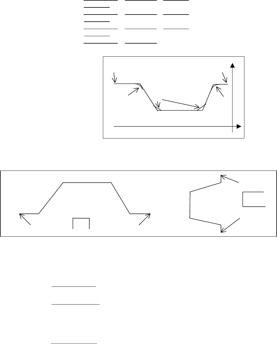
G131 X End point X Z End point Z R corner-R
C Chamfer
; (the 2
nd
point)
G131 X End point X
Z End point Z R corner-R
C Chamfer
; (the 3
rd
point)
G131 X End point X
Z End point Z R corner-R
C Chamfer
; (the 4
th
point)
G131 X End point X
Z End point Z ; (End point)
G139 ; (End of figure)
The Groove figure also can be specified by the Sub Program like the Bar
machining.
(2) The detail of
the process data
B Machining area 0=Outer, 1=Inner, 2=Face
(When “B_” is not specified, “Machining area” is equal to B0)
A Diameter/Radius
0= Specify arguments as X Diameter and Z Radius
1= Specify arguments as X Radius and Z Radius
(In case of using the PMC signal for selecting Diameter/ Radius,
this argument cannot be used. )
F Cutting feedrate
Cutting feedrate of Grooving.
If the unit of the feedrate is Feed/min or Feed/rev, it is accordance
with the Feed/min or Feed/rev command of the previous block.
(When “F___” is not specified, the previous feedrate is used)
+Z
+X
Start point
•
1
st
point
2
nd
point
3
rd
point
4
th
point
End point
Corner-R/Chamfer
Corner-R/Chamfer
•
•
•
•
•
•
•
•
• •
•
•
•
•
•
•
•
(Inner Groove)
(Face Groove)
Start point End point
End point
Start point
Tool
Tool
•
Fig.4.1.2
Fig.4.1.3
Contents Summary of Series 16i/18i-MA/MB Canned Turning Cycle for Milling Machine, Specification Additional Manual
- Page 1Series 16i/18i-MA/MB Canned Turning Cycle for Milling Machine Specification A-78538E/08
- Page 2In order to use this turning cycle for milling, it is necessary to set the parameter 9641<#7+#6> to 1. Canned Cycle for Bar Machining Bar Roughing and Finishing can be programmed as Canned Cycle. 1.1 Roughing Cycle/ Outer/Inner/Face Roughing Cycle is executed by using the G700 and G1xx command like
- Page 3(Note) Don’t change the order of the argument I J K. For instance, don’t put the argument J after the argument K. The order of the argument must be programmed in order of I J K according to the argument specification of custom macro. (Note) In G700 Roughing, Tool nose radius compensation is performe
- Page 4Specifying the Rough shape In case of cutting work piece with the Rough shape like the following figure, Fig.1.1.3, it is necessary to specify the Rough shape. An operator specifies the points making up the Rough shape. Each points of the outer and inner of the Rough shape can be specified up to the
- Page 5(2) The detail of the process data The detail of the process data, the arguments of G700 block, is as follows. P Cutting direction 0= Outer/Inner/Face 1= Outer Reverse/Inner Reverse/Face Reverse ( When “P_” is not specified, “Cutting direction” is equal to P0) Outer Inner Face +X +X +X +Z +Z +Z Oute
- Page 6* K minimum cut amount The cut amount calculated as above is clamped by this specified argument like the cut amount does not become less than the argument amount. (When “K___” is not specified, “minimum cut amount” is equal to K0) I allowance of end face Before starting the Outer roughing, the end f
- Page 7Tool motion of cutting the end face is as follows. (1) Tool moves to the position “Z1=Zs-Q” along Z-axis at G00 (2) Tool moves to the position X0 along X-axis at G01 (3) Tool escapes to the position “Z1+release amountP9798” along Z-axis at G00 (4) Tool returns the position X1 at G00 (5) Tool moves t
- Page 8R Nose angle Angle of the tool tip. (When “R__” is not specified, the parameter 9810 is used as Nose angle) In case of that pocket figure was inputted as the machining figure, cutting back compensation will be done as the following figure Fig.1.1.8. Cutting Edge Compensation +X Cutting Back Compensa
- Page 9180 - (Q+R) - P9801 <= 0.0 degree TLBACK TLBACK R R Q Remained residual Q cutting part Fig.1.1.10 D Imaginary tool tip position It is commonly used with ISO programming. (When “D_” is not specified, “Imaginary tool tip position” is equal to D0) 2 6 1 9,0 +X 7 5 3 8 4 +Z Fig.1.1.11 T Offset No. Offse
- Page 10* X/Z End point X,Z End point of the Rough shape B Outer/Inner 0= Outer shape 1= Inner shape (When “B_” is not specified, “Outer/Inner” is equal to B0) (Note) Before calling this canned cycle, Tool nose radius offset must be cancelled and X-Z plane, G18, must be selected. (Note) In order to use this
- Page 11
Finishing figure When a Cutting start point exists in this area, Semi-finishing is executed. When a Cutting start point exists Minimum X of Finishing figure in this area, Semi-finishing is not executed. Fig.1.1.14 Example: In case of the cutting start point P1, semi-finishing is not - Page 12Example of Programming +X 1 ° Cutting start point R2.5 Ø 70 71 R5 Ø 60 ● Ø50 Ø2 Ø 60 Ø 40 Ø 20 +Z 17.5 10 5 20 1 40 15 15 Fig.1.1.16 (Diameter designation, metric input) : G40 X____Y____; ------ Offset cancellation G18 ; ------ Select X-Z plane G68 X0Y0Z0I0J1K0R-90.; ------ Convert Z-axis to X-axis
- Page 13G101 Z-35.; G102 X50. Z-40. R5.; G101 X55.; G103 X60. Z-42.5 R2.5 ; G101 Z-60. ; G101 X70.; ------ the last figure of the finishing figure G139 ; M99 ; (Note) The example of the figure blocks is programmed in the diameter units for X-axis. So it is necessary to set the PMC signal G296.0 to 1 for exe
- Page 142) Cutting start points of [INNER] X = [Xmin : Minimum inside coordinate of a figure] - [CLRX] Z = [Zs : Z coordinate of figure start point] + [CLRZ] 3) Cutting start points of [FACE] X = [Xs : X coordinate of figure start point] + [CLRX] Z = [Zmax : Maximum Z coordinate of a figure] + [CLRZ] 4) Cut
- Page 151.2 Finishing Cycle/ Outer/Inner/Face Finishing Cycle is executed by using the G710 and G1xx command like the following figure. And also, this Cycle is used in X-Z plane. +X Tool Cutting start point E W F Finishing figure U +Z Fig. 1.2.1 (Note) Before commanding Finishing Cycle, a tool must be moved
- Page 16F Cutting feedrate Cutting feedrate of Bar Finishing. Whether unit of the feedrate is Feed/min or Feed/rev, it is accordance with the Feed/min or Feed/rev command of the previous block. (When “F___” is not specified, the previous feedrate is used) * U Finishing allowance X X direction amount of semi
- Page 17(4) About the meaning and difference of Roughing, Semi-finishing and Finishing
Remove the specified part except the finishing allowance (Roughing motion) Finishing allowance path Fig.1.2.4 Finishing figure path Remove the remained part in roughing along t - Page 18Canned Cycle for Threading Threading can be programmed as Canned Cycle. 2.1 Threading Cycle/ Outer/Inner Threading Cycle is executed by using the G720 and G12x command like the following figure. And also, this cycle is used in X-Z plane. +X Tool Cutting start point Y U H V L W +Z Fig.2.1.1 (Note) Be
- Page 19(Note) Chamfering cannot be specified. (Note) Specify the end point and start point of the thread as the following figure. (Note) T-argument is nou used for the tool offset in this cycle. (Note) In this cycle, G41/G42 is cancelled. (Note) In this cycle, chamfering can not be specified. It, therefore
- Page 20Unified type is performed according to the unified thread standard. In case of specifying the lead of thread in “the number of thread per inch” units, specify Unified type. * Q Cut amount Specify the Depth of cut for the first pass or Number of cuts. The meaning of “Q” is accordance with the specifi
- Page 21Single edge cutting, Constant cutting depth C=4 In case of Q=0.1, dn is calculated as follows d1=Q=0.1 d2=Q=0.1 d3=Q=0.1 D d4=Q=0.1 D d5=Q=0.1 H : D u Zigzag cutting, Constant cutting depth C=5 In case of Q=0.1, dn is calculated as follows d1=Q=0.1 d2=Q=0.1 D d3=Q=0.1 D d4=Q=0.1 D d5=Q=0.1 H : D u S
- Page 22Example) In case of the Lead L=1.2 mm, Number of thread P=2 and Cutting start point Z1 = 1.25
First cutting depth At first, thread cutting starts at the point Z1=1.25 Next, the tool returns to the point Z2 =1.85 which Z1 is shifted to the Second cutting depth right directio - Page 23Example of Programming Cutting start point 5. 1.5 2.5 1.2 U 0.25 2.5 Ø30. 3. H 20. 8. +Z Fig.2.1.6 (Diameter designation, metric input) Parameter for Clearance X, Z P9830= 1200 O0225 G40 ; ------ Offset cancellation M10 ; ------ Set X-axis diameter mode (PMC signal G0296
is turned : on to 1) G6 - Page 24Canned Cycle for Normal Grooving Normal Grooving can be programmed as Canned Cycle. 3.1 Normal Grooving Cycle/ Outer/Inner/Face Normal Grooving Cycle is executed by using the G730 and G135 command like the following figure. And also, this Canned Cycle is used in the X-Z plane. +X In case of H=0 E To
- Page 25(2) The detail of the process data and figure data B Machining area 0=Outer, 1=Inner, 2=Face (When “B_” is not specified, “Machining area” is equal to B0) A Diameter/Radius 0= Specify arguments as X Diameter and Z Radius 1= Specify arguments as X Radius and Z Radius (In case of using the PMC signal
- Page 26R Dwell time Dwell at the bottom of a groove in roughing. (When "R___" is not specified, "Dwell time" is equal to zero) Unit : sec W Groove width Width of a groove to be machined. (when "W___" is not specified, P/S alarm will occur) D Groove depth Depth of a groove to be machined. (When "D___" is no
- Page 27H Cutting method 0 = A tool cuts into the center of a groove at first, and expands its cutting area to left and right part from there (Bi-direction) 1 = A tool cuts into the work end face side of a groove at first, and expands its cutting area toward chuck side. (Uni-direction) See Note about the de
- Page 28Ovl = amount of overlapped tool(%) E = tool width d = cutting width “d” is calculated as E(1-Ovl/100) Zs = Entered start point Z of groove Ze = end point Z of groove is calculated as Zs+W W = Entered width of groove Tool moves from point Z1 as follows. Z2 ÆZ2ÆZ3Æ…ZnÆZn+1ÆZcÆZl1ÆZl2Æ…ÆZn-1ÆZlnÆZln+1
- Page 29Example of Programming +X Cutting start 1.5 Point 5. Ø40. 10. Ø30. 5. 25. +Z 30. Fig.3.1.9 (Diameter designation, metric input) O0333 G40 X70. Z50. ; ------ Offset cancellation M10 ; ------ Set X-axis diameter mode (PMC signal G0296
is turned : on to 1) G68 X0 Y0 Z0 I0 J1 K0 R-90. ; ------ Conv - Page 30Canned Cycle for Trapezoidal Grooving Trapezoidal Grooving can be programmed as Canned Cycle. 4.1 Trapezoidal Grooving Cycle/ Outer/Inner/Face (Roughing) Trapezoidal Grooving Cycle is executed by using the G740 and G13x command like the following figure. And also, this Canned cycle is used in the X-
- Page 31G131 X End point X Z End point Z R corner-R C Chamfer; (the 2nd point) G131 X End point X Z End point Z R corner-R C Chamfer; (the 3rd point) G131 X End point X Z End point Z R corner-R C Chamfer; (the 4th point) G131 X End point X Z End point Z ; (End point) G139 ; (End of figure) Start point End p
- Page 32E Tool width Width of grooving tool at cutting edge.( When "E__" is not specified, P/S alarm will occur) Overlaps between each cutting in grooving (proportion to the Tool width) are set to the parameter 9825. * Q Cut amount Infeed amount of the first cutting motion (When “Q___” is not specified, P/S
- Page 33P Pitch Distance between grooves when grooves of the same figure are machined at regular intervals. (When "P__" is not specified and Number of grooves more than one groove is specified, P/S alarm will occur) H Cutting method 0 = A tool cuts into the center of a groove at first, and expands its cutti
- Page 34Zl3 = Zl2 – d : Zln-1 = Zln-2 – d Zln = Zn-1– d In case of n=0, a tool moves as follows. Zs Zc Tool moves in the following order (2) (3) (2) Æ (2) Æ (3) (1) Fig.4.1.6 Example of Programming 5. Cutting start Point 1. 5. ● ● Ø55. Ø50. Ø50. Ø50. Ø50. Ø2. 5. 5. 15. 5. 5. 5. Fig.4.1.7 (Diameter designati
- Page 35M30 ; O3311 G130 X50. Z-50. A0.; ------ Start point G131 Z-45. R4. ; ------ 1ST point G131 X20. Z-40. R4. ; ------ 2nd point G131 Z-25. R4. ; ------ 3rd point G131 X50. Z-20. R4. ; ------ 4th point G131 Z-15. ; ------ 5th point G139 ; ------ End of figure M99 ;
- Page 364.2 Trapezoidal Grooving Cycle/ Outer/Inner/Face (Finishing) Trapezoidal Grooving Cycle is executed by using the G750 and G13x command like the following figure. And also, this Canned Cycle is used the X-Z plane. Tool E Start Point F Fig.4.2.1 (Note) Before commanding trapezoidal Grooving Cycle, a t
- Page 37Example of Programming Tool 5. Cutting start Point 1. ● ● Ø55. Ø50. Ø50. Ø50. Ø50. Ø2. 5. 5. 15. 5. 5. 5. Fig.4.2.2 Refer to the explanation of “Example of Programming” of “4.1 Trapezoidal Grooving Cycle”.
- Page 38MACRO RESOURCE in case of using User Macro In case of using User Macro programs with Turning cycle for Milling, user can use only the following program number and the macro variables. (1) User available P-code program number : O5000 to O9999 (2) User available common variables : #500 to #531 , #100
- Page 39ALARMS Alarm Description 3001 Cause The value of process data such as the machining area is incorrect. Example) A minus value is entered for an item that must be positive. Action Check the entered process data values. If there is an incorrect value, enter a correct value. 3005 Cause The value for th
- Page 40PARAMETERS ! WARNING Be sure to use the parameters set by the machine builder. If you change the setting of a parameter, the machining program may not work correctly. If the machining program does not work correctly, the tool may bump against the work-piece, and the machine may be forced to perform
- Page 41Note) According to the position of the cutting start point and the end point of an entered figure, semi finish machining may be carried out, regardless of the value set in the parameter Start point of a figure Cutting start point : Semi finish machining is carried out unconditionally Cutting start p
- Page 42TLBACK 9809 CUTANG CUTANG Default value of cutting edge angle for bar machining. Valid data range : 0 to 1800 Units : 0.1 degree 9810 TIPANG TIPANG Default value of tool tip angle for bar machining. Valid data range : 0 to 1800 Units : 0.1 degree A.3 Parameter for Grooving 9820 CLGRVX CLGRVX Clearan
- Page 439824 GRVBCK GRVBCK Pecking clearance for grooving (radius). Valid data range : 0 to 99,999,999 Units : 0.001mm 0.0001inch 9825 OVLGRV OVLGRV Overlaps between each cutting in grooving (proportion to the tool width). Valid data range : 0 to 100 Units : 1% A.4 Parameter for Threading 9286 ISCWCF ISCWCF
- Page 449831 CLSCRZ CLSCRZ Default value of the acceleration distance (radius) of the Z axis for threading. Valid data range : 0 to 99,999,999 Units : 0.001mm 0.0001inch CLSCRX CLSCRZ 9832 SCWCF SCWCF Coefficient for the height of a general thread. Valid data range : 0 to 32,767 Units : 1/10000 The system a