FANUC AC Servo Software 90A3 / 90A7 Series, 90B3 / 90B7 Series Learning Function, Operator Additional Manual Page 14
Additional Manual
Title 90A3 / 90A7 / 90B3 / 90B7
Learning Control Operator’s Manual
03 ’05.01.13 K.Maeda 3
rd
. updated. Draw No.
02 '03.01.06 K.Maeda 2
nd
. updated
A - 63639E - 070
01 ‘00.09.20 K.Maeda Newly designed Sheet 014
Edit Date Design Description
/ 081
(Example 2) In the following configuration, set 1, 2, 3 and 5 for No.1023.
Axis name Servo axis number
X axis 1
st
axis (Learning axis)
Z axis 2
nd
axis
C axis 3
rd
axis (Learning axis)
Y axis 5
th
axis (High speed axis)
(Note) In case setting Learning axis for the 3
rd
axis, you can not allocate a normal axis for the 4
th
axis.
In 90A7 series, you can allocate a normal axis for the 4
th
axis.
(Note) If you set –128 for No.1023, the axis is recognized as a dummy.
(Example 3) In the following configuration with α300 or α400, set 1, 3, 4 and 5 for No.1023.
Axis name Servo axis number
X axis 1
st
axis
C
1
axis 3
rd
axis (Tandem axis)
C
2
axis 4
th
axis (Tandem axis)
Y axis 5
th
axis (High speed axis)
(Note) You should set α300 or α400 to Tandem axis. This motor occupies two servo axes that are the
odd and the subsequent even number.
• You must set No.1817#6 of both main and sub axes to 1. (Tandem control is the software
option.)
• You must set No.2018#7 of the sub axis to 1.
♦ Tandem control is available from the following edition.
9083/02 or later, 9087/02 or later (plan), 90A3/02 or later, 90A7/01 or later
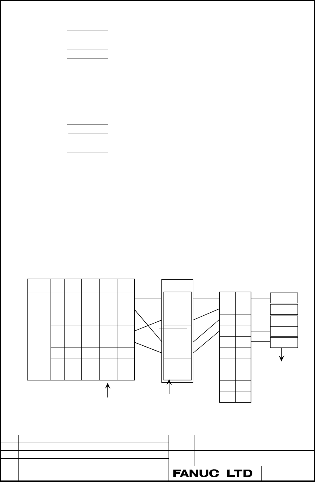
5.1.2 FSSB setting
You should think the allocation of axis number (No.1023) and amplifier number (No.1910-) because the
connection from CNC to amplifier is serially linked by optical cable (FSSB interface) in i-series.
Refer to the following example.
Fig. 5.1.2 FSSB setting example
CNC
Axis
Path 1
1020
Name
1905
#0
1936 1023
1
2
3
4
5
6
7
8
X
Z
C
Y
A
0
0
−
0
1
0
−
−
−
−
1
5
-1
3
6
1 − 0
Axis Card
1
2
3
4
5
6
7
8
9
10
0
2
4
5
16
40
40
40
40
40
1910-
Slave
Fast
X
Y
Z
A
Servo Amp.
Fast
Fast
Slow
1905#7,#6 = 01
M1
Scale
2 − 1
3 − 2
4 − 3
5 − 4
6 − 5
7 − 6
8 − 7
Servo Axis Number
Contents Summary of FANUC AC Servo Software 90A3 / 90A7 Series, 90B3 / 90B7 Series Learning Function, Operator Additional Manual
- Page 1FANUC AC SERVO SOFTWARE 90A3 / 90A7 Series 90B3 / 90B7 Series LEARNING FUNCTION Operator’s Manual 1. Overview 2. System Configuration 3. Application Examples 4. Explanation of Learning Control 5. Servo parameters 6. Learning Control functions 7. Functions detail 8. Adjustment 9. Attentions Appendix
- Page 2Contents 1. Overview ……………………………………………………………………………………. 3 2. System Configuration ………..…………………………………………….…….………... 5 3. Application Examples ………..…………………………………………….…….………... 6 3.1 Lead Cutting ……..……………………………………………………….…….…….. 6 3.2 Piston Lathe …….…..…………………………………………………….…….…..… 7 3.3 Cam grinder ……
- Page 31. Overview This manual describes the only special servo functions and parameters relating to High-speed Cutting and Learning function used in FANUC Digital AC Servo. With respect to the information of the standard servo function for general cutting tools, you can get it from “FANUC AC SERVO MOTOR α
- Page 4(Note 1) The Learning function by digital servo software enables high-precision control for the command and the cutting disturbance that is given repeatedly at specified intervals. For example, the lead for video cam drum, the piston or the camshaft for car engine is usually made with a conventional
- Page 52. System Configuration High-speed cutting (G05) can be achieved using three below cases. Fig.2-1 shows a system configuration. (1) Memory operation by “High speed cycle cutting” a) To produce cutting data by Open CNC or personal computer and down load to P-code area of CNC. b) To produce cutting da
- Page 63. Application example 3.1 Lead cutting machine Fig. 3.1.1 Configuration example of Lead Cutting Machine (1) The tape running surface is cut synchronized to the spindle rotation, moving the tool 1 back and forth along the Y-axis. By feeding the tool along the Z axis, the lead surface is gradually cu
- Page 73.2 Piston Lathe Piston axis Y axis Oval cross Section Piston Work X axis Double slide mechanism Z axis Fig. 3.2.1 Configuration example of piston lathe * Cutting Sequence (1) The piston outside is cut by rotating the spindle to move the tool back and forth along the Y axis. By feeding the tool alon
- Page 83.3 Cam Grinding Machine Profile 1 Profile 3 A A - A' cross section C axis Profile 2 Profile 4 CAM work Grinder Grinding tool A' X axis Spiral grinding CAM work Z axis Single slide mechanism Fig. 3.3.1 Example of Configuration of Cam Grinding Machine. * Grinding Sequence (1) The cam form is ground s
- Page 91'st cutting step 2'nd cutting step 3'rd cutting step G05 start G05 end Approach LESTTM L2 PRIOD2 L1 X axis L1 PRIOD Learning start The 2'nd Repetitive count Repetitive count RPTCT2 RPTCT 1/L1 Average speed C axis 1/ L2 Average speed L1 , L2 : C axis rotation period Fig. 3.3.3 Cutting Chart (when pr
- Page 104. Explanation of Learning Control 4.1 Summary of Learning Control FANUC Learning function Learning control Preview Repetitive control Learning Learning Adaptive Preview controller controller controller What is “Learning Function” ? It is a function for realizing high-speed and high-precision cuttin
- Page 114.2 Learning Control Learning controller Suspension Continuation G0(s) + Command 1 Kp + + s - Position Error Position Motor Gain Position feedback [ Merit ] Replacing the mechanical cam tracing method with the electric master cam. Minimized position error for repetitive command with specified period
- Page 12command within one profile gradually change due to cutting feed, such as the case of single slide mechanism. (Note) Compensation data mode means that Learning data is not clear at G05 finish. Both Suspension and Continuation mode clear it every time G05 finish. And it takes some times to clear. So w
- Page 135. Servo parameters 5.1 Setting parameters (Series 16i) 5.1.1 Setting CNC parameters CNC parameters setting related to High-speed Cutting are explained. For the detail, refer to the “FS 16i / 18i / 160is/ 180is model B Parameter Manual”. (1) Set the following parameter. • No.1004 (Bit type) B1=1, B0
- Page 14(Example 2) In the following configuration, set 1, 2, 3 and 5 for No.1023. Axis name Servo axis number X axis 1st axis (Learning axis) Z axis 2nd axis C axis 3rd axis (Learning axis) Y axis 5th axis (High speed axis) (Note) In case setting Learning axis for the 3rd axis, you can not allocate a norma
- Page 15(Caution) In case of HRV3 In case of HRV3, you should read 4.3 servo HRV3 control in “FANUC AC SERVO MOTOR αi series Parameter Manual”. You should be careful with the followings. 1) Hardware (Servo axis control card, Servo Amplifier, Outer detector I/F unit) 2) Software (CNC software, Servo software
- Page 16Feedback pulses before F.F.G per one motor rotation = 8mm / (4µm / 512) = 1024000 P/rev 4 [ µ m ] 512 40 5 SDMR1 = = → 0 . 1[ µ m ] 512 64 SDMR2 No.2024 = 1024000 / 100 = 10240 No.2185 = 100 (Example 6) Full-closed linear axis, linear scale (4µm pitch) + High precision serial output circuit H (A860-
- Page 175.2 Setting High gain parameter In case of using Learning control for Cam grinder etc, and the position error does not converge due to the influence of disturbance, it is recommended to use the High gain setting. Refer to “Appendix 3. Parameter table for Learning control”. "High gain setting" means
- Page 185.3 Servo HRV3 setting As Learning series bases on standard series, refer to "FANUC AC SERVO MOTOR αi series Parameter Manual" (B-6570E). HRV3 is available for Learning series of 90B3 and 90B7. The following describes the special points in Learning series. (Note) From 90B3/08(H) or later and 90B7/08
- Page 195.3.3 FSSB connection (1) Case of one FSSB path All slave units (Servo amplifier or Outer detector I/F unit) need to be suitable for HRV3. And you must set the HRV2 or High gain setting for all axes without Piston axis. Servo axis control card Servo Amplifier Servo Amplifier Servo Amplifier Outer de
- Page 205.4 Servo parameters List The following parameters number are for FS16. The shaded parameters are detailed in this manual. B7 B6 B5 B4 B3 B2 B1 B0 2000 PGEX DGPR PLC0 2002 2003 VOFS OVSC BLEN NPSP PIEN OBEN TGAL TIA1 2004 DLY1 DLY0 TIB1 DLY2 TRW1 TRW0 TIB0 TIA0 2005 SFCM BRKC HSPEED 36RPC FEED 2006
- Page 212203 RPL246 TCMDX4 1/2PI 2206 HSSR OVCRST 2207 DBDNEG PK2D50 NEGSHC 2208 TRMXT 2209 SAL2HC 2210 HSSR PK12S2 2212 OVQK 2213 OCM 2214 2223 DISOBS 2226 MEMCL PRFCLR FFEXP SVGDCG 2227 ANGLRN ANGREF 2228 VFB2MS FRQ VFB500 VFB1MS HSBLC SYSLRN 2229 TAWAMI STPRED HSSATU RCNEG TIMADJ ABSEN This bit type para
- Page 222079 FB coefficient denominator for Dual Check Safety 90B3/I 2107 Velocity gain override (%) 90B3/I 2110 MGSTCM Magnetic saturation compensation coefficient 9083/A 2112 AMR1 conversion coefficient 2113 Center frequency for resonance eliminate filter (Hz) 90A3/B 2119 Stop judgment level for PK2V chan
- Page 232237 RPTCT3 3rd repetition count (cycle) 2238 PRIOD3 3rd Learning period (msec) 2239 RPTCT4 4th repetition count (cycle) 2240 PRIOD4 4th Learning period (msec) 2241 SFTTH1 Manual thinning count Don’t use. fix to 0 2242 RPTCT 1st repetition count (cycle) 2243 PRIOD 1st Learning period (msec) 2244 FBN
- Page 242261 FORW6 Feed forward coefficient W6 2262 SHKRDC Shock reducing counter 2263 TAWA1L Torsion compensation coefficient during G05 9083/B 2264 PRFALL Total profile number 9087/A 2265 RPTCT5 5th repetition count (cycle) 9087/A 2266 PRIOD5 5th Learning period (msec) 9087/A ♦ Gx : Dynamic characteristic
- Page 252335 Velocity gain magnification (HRV3) 90B3/I 2359 HRV filter damping 90B3/D 2360 HRV filter central frequency 90B3/D 2361 HRV filter 2 damping band width 90B3/D 2362 HRV filter 2 damping 90B3/D 2363 HRV filter 3 central frequency 90B3/D 2364 HRV filter 3 damping band width 90B3/D 2365 HRV filter 3
- Page 265.5 Servo parameter detail If not necessary, don’t change the standard parameters of Auto loading. In case of specifying Series and edition, you can use the function from that edition or later. 2003 VOFS OVSC BLEN NPSP PIEN OBEN TGAL TIA1 PIEN Velocity loop is 1 : PI control 0 : IP control 2005 SFCM
- Page 272018 PFBCPY REVS PFBCPY Motor feedback is taken from (Sub axis only) 1 : L-axis. 0 : M-axis. (standard) ♦ In case of α300 or α400 or connected Linear motor, set this bit to 1 with Tandem control. 2200 PK2VSF EX2V PFBSFT OVRNSP 2201 VOCECM RUNLVL CROF PK2VSF Velocity proportional weight (9087/01 or l
- Page 282228 VFB2MS FRQ VFB500 VFB1MS HSBLC SYSLRN 2229 TAWAMI STPRED HSSATU RCNEG TIMADJ ABSEN VFB2MS Velocity feedback is (9087/01 or later) 1 : special. (2msec) ♦ This bit is effective to reduce high frequency 0 : standard. (1msec) oscillation in High gain setting. VFB500 In High-speed Proportional gain,
- Page 292067 FILTER Tcmd filter coefficient Standard : 0 Set by the following expression. fc : Cut-off frequency [Hz], τ : Sampling time [sec] (Setting value) = 4096 × exp(-2µ×fc×τ) (Example 1) Case of normal axis (τ = 1msec) and fc = 100 [Hz] No.2067 = 4096 × exp(-2π×100×0.001) = 2185 (Example 2) Case of h
- Page 302175 RSHFTL R-phase current offset compensation coefficient 9083/B 2176 SSHFTL S-phase current offset compensation coefficient 9083/B Data range : from –20 to +20 Standard : 0 You should not change this parameter from standard setting value. If the current offset caused the torque ripple of a quarte
- Page 316. Learning Control function 6.1 Learning Control parameters 2007 ILMTRL STPRED ADERSL VCMDCL UNTSL TRASMT ADAPT VELHSP 2008 INVSYS ICM SLEN LCON EXGX MSCHK (TNDM) LSTP SLEN Learning control (Option) is 1 : Available. ♦ If you change SLEN, you must turn off and on CNC. 0 : Not available. (Power must
- Page 32the renewal of the compensation data only during the first period subsequent to Learning step switching. This might have good result on such grinding application that have many and rapid Learning step change. 2242 RPTCT 1st Learning count (Repetition count) [cycle] Data range : 0 to 32767 Standard :
- Page 33When this parameter is set, Learning controller repeats the learning steps. (Example) In case No.2232 = 2, Learning steps exist up to the 3rd Learning step. 1st → 2nd →3rd → 1st → 2nd → 3rd → 1st → 2nd → 3rd 0 1 2 2264 PRFALL Total profile number 9087/A Data range : 0 to 16 Standard : 0 If you can u
- Page 34final cycle. Servo software judges the final cycle by the Learning count (No.2242, No.2235, or etc). 2244 FBND Frequency band of low pass filter [Hz] Data range : 0 to 700 stepping up every 50 (When Velocity 0.5msec) 0 to 350 stepping up every 25 (When Velocity 1msec) Standard : Refer to Appendix 3.
- Page 35In case of Expanded Gx chosen with EXGX (No.2008#3 ) one set, you need to set for the following parameters. 2249 EXGXK2 Coefficient 2 of expanded Gx 2250 EXGXK 3 Coefficient 3 of expanded Gx 2251 EXGXK 4 Coefficient 4 of expanded Gx 2252 EXGXK 5 Coefficient 5 of expanded Gx 2253 EXGXK 6 Coefficient
- Page 36Profile 1 Profile 5 Com m and Com m and G05 G05 Learning Controller W hen IC M=0, MC is Mem ory clear switch (MC) available at tim e of G05 finish. Profile 1 (Mem ory) Low pass filter Profile 2 + No.2244 (Mem ory) All profile num ber No.2264 F(z-1) + Suspension (LCO N) Profile 5 (Mem ory) Dynam ic c
- Page 376.2 Adaptive Preview Control Parameters 2007 ILMTRL ADERSL VCMDCL UNTSL TRASMT ADAPT VELHSP 2008 INVSYS ICM SLEN LCON EXGX MSCHK (TNDM) LSTP INVSYS Adaptive Preview Control is 1 : Available. ♦ CNC software option is necessary 0 : Not available. (Note) If you use this function, you must set to 1 for
- Page 382256 FORW1 - − Feed forward coefficient W1 - W6 2261 FORW6 Data range : -32768 to 32767 Standard : 0 Feed forward coefficients FORWi are usually decided by Adaptive mode. Also you can calculate by the following expression. fi PULCO SMDR2 1 FORWi = × 216 × × × 100 PPLS SMDR1 80 fi PULCO = × 216 × 100
- Page 396.3 Adaptive method The feed forward coefficients of the Adaptive preview control are decided with the following procedure. A-1 Validate the Adaptive preview control and the Adaptive mode. ( No.2008#7 = 1 and No.2007#1 =1 ) A-2 Set the parameter of the forward order and the adaptation coefficient to
- Page 407. Functions detail 7.1 Learning Memory expanded function Learning Memory expanded function allows the application to take advantage of many profiles up to Max. Profile number and many learning steps up to Max. Learning step number as the following table. (Option) This function is available in the f
- Page 412226 LCT2WD LEBFEX Learning period is (90B7/N, 90B3/O) 1 : Available (2 words type) 0 : Not available (conventional type) (Note) When this bit is available, Learning period is the product of the following two parameters. But Learning step is fixed to the first step. 2243 PRIOD1 1st Learning period (
- Page 427.1.2 Processing flow Grinding start Grinding condition change Select Grinding program Set Total profile number according to camshaft G10 Set ∗ Profile number, Learning Change Total profile number period, Repetition count, G10 or ? No Memory clear bit Compensation mode invalid etc. Yes Clear out all
- Page 437.1.3 Cautions Learning memory expanded function realize the specification by the learning memory to alter a sample rate. It have automatically the sampler gather the data roughly every 2 to Nth power in case of long Learning period or many profiles and Learning steps, because of which case many com
- Page 447.2 Learning Data Transmission Function 7.2.1 Overview For the purpose of preserving the servo learning data after NC powered off, The learning data can be preserved in the hard disk device (HD), which store the learning data through CNC and load it the memory of servo control. (Learning data transm
- Page 457.2.3 Servo parameter In order to transmit (save and load), the below setting is necessary. No.2008#5=1 : Enable Learning Control No.2008#6=1 : Enable Compensation data mode You must take care the following parameters when you save and load the Learning Data. No.2233 : PRFNO: Profile number No.2264
- Page 46To LOAD Learning Data (HD → Servo ) 1) Set No.2233 of the Profile number to zero in case of the lump deal method. Learning Data saved by the lump deal method must be loaded by the lump deal method. Check No.2264 of the total number of Profile to be same value as saved before.(It must be so!) Set No.
- Page 47Examples (1) Correspondence with processing program and Work Total profile number O0001 ; Profile i Profile j G10 L50 ; C axis N2264 P (Axis) R (Total profile number) ; G11 ; G10 L50 ; Grinding N2233 P (Axis) R (Profile number i) ; X axis CAM work N2242 P (Axis) R (Learning count) ; N2243 P (Axis) R
- Page 48(2) Example of file management by Partial deal method We describe the case that Work 1 and Work 2 on right figure is processed in that order. This case suppose PC has already Learning data in the HD of A,B,C,D,E,F. A B C D 1) At first you should fix Total profile number PRFALL to 4 . 2) According to
- Page 497.3 Ultra high precision velocity feedback function (Rotary axis) 7.3.1 Summary In 90A7 or 90B7 series, Ultra high precision velocity feedback ( Abbreviation : separate semi-closed ) function can be realized by using the absolute rotary encoder RCN723F or RCN223F (223 resolution) made by Heiden-Hain
- Page 507.3.5 The limitation for maximum speed • Maximum speed is limited by the performance of both servo software and encoder. Concerning encoder, refer to the specification for encoder. On the other hand, there are the following speed limitation in servo software. In case of high gain setting ( cf. 5.2,
- Page 517.4 Torsion compensation during high speed cycle cutting function This function adds the compensation at the point of the command reversing sign during high speed I/F mode (G05), This function is useful for the case that the reverse point of work piece has sharp drop because it is easy to bend for t
- Page 527.5 Tandem Learning control function 7.5.1 Summary Tandem Learning control is Learning control combined with Tandem control. By means that two motors are controlled as one axis and Learning control is added, this function can achieve high precision processing in the special applications. 1) Position
- Page 53side chucking, set this bit to 0 to enable “Sub axis separation function” exclusively or “Synchronous Learning function”. Of course the double coils tandem requires TANDEM to be one due to the former case. 1023 Servo axis allocation You should set Main axis to the odd (L-axis), Sub axis to the subse
- Page 542087 Preload torque (Note) Set for both Main and Sub axes. Set zero in case of double coil tandem or the position tandem learning control. Set a value that is as small as possible but greater than the static friction torque. A set preload torque is applied to each motor at all times. So, set a value
- Page 55You set No.8311 for the relation between Main and Sub axis. Refer to 1.6 Simple Synchronous control in “FANUC Series 16i-Model B Connection Manual (Function)” (B-63523EN). In addition, Coupling flag is available from the following CNC software edition. All i-model B, B0F1/20 (FS16i-MA), B1F1/18 (FS1
- Page 568. Tuning Regarding Learning control, you don’t need to tune parameters basically. But servo system needs to be stable before the application of Learning control. If oscillation occurs, you need to make stable by tuning Load inertia ratio (No.2021), Acceleration feedback (No.2066), Tcmd filter (No.2
- Page 579. Attentions 9-1. ITP Delay Alarm In case that CNC operation is delayed during G05 (High-speed cycle cutting or High-speed DNC operation), work piece is not processed normally. For this reason, High-speed axis checks this delay (ITP delay) during G05. You can confirm that whether this delay happene
- Page 589-5. Axis allocation of 2 controlled paths in i-series In case that you allocate Servo axis by No.1023 in 2 controlled paths in i-series, you must not allocate the servo axes of the another controlled path to one servo DSP. (Bad example) [1st path] X1 axis No.1023 = 1 → L-axis of 2 axes amplifier ••
- Page 59Ref. Full-closed system In series 16 or 18 (Model B or C), Servo axis module (A20B-2902-0061) for Learning control does not support separate serial pulse coder. You should use the scale or encoder of A/B phase type. In addition, Servo axis module for standard (A20B-2092-0070) does not have this rest
- Page 602115 Inside data measurement Series Odd axis Even axis Remarks 90A3 310 950 113h(L), 13Bh(M) 90A7 (136h) (3B6h) 90B3 310 2358 113h(L), 193h(M) 90B7 (136h) (936h) Title 90A3 / 90A7 / 90B3 / 90B7 Learning Control Operator’s Manual 03 ’01.01.13 K.Maeda 3rd. updated. Draw No. 02 '03.01.06 K.Maeda 2nd. u
- Page 61Appendix 1. Notes on the order 1-1. Servo axis Card (i-series) You must specify the Main CPU card for Learning Control in i -series. • 2 axes A02B-0236-H015 • 4 axes A02B-0236-H016 • 6 axes A02B-0236-H017 • 8 axes A02B-0236-H018 You must specify the following Servo axis card for 90A7 series. • 6 axe
- Page 621-5. Dual Check Safety (edition matching between CNC software and Servo software) When you use the Dual Check Safety function, you need use the following Servo software. • 90B3 series / 09(I) edition or later (Series 16i -B, 18i -B) • 90B7 series / 04(D) edition or later (Series 16i -B, 18i -B) When
- Page 63Appendix 2. Making method for cutting data PROFILE 2 PROFILE 1 X-axis RIFT C-axis ANGLE MMC or Personal Computer X-axis RIFT C-axis ANGLE 1cycle 1cycle P10004 BINARY DATA P10001 X-axis Command per C-axis Command per Distribution cycle Distribution cycle ∗ Distribution cycle = 0.5msec, 1msec, 2msec D
- Page 64Appendix 3. Parameter table for Learning control Standard Parameters for Learning Contorl (Piston) 1/5 Motor type αL9 αL9 αL9 αL6 αL6 Motor spec. 0564 0564 0564 0562 0562 Motor ID 74 74 (74) 75 75 Velocity 0.5ms(HS) 0.5ms(HS) 250us(HS) 0.5ms(HS) 0.5ms(HS) Remarks Piston Lead Cam Piston Lead Cam Lead
- Page 65Standard Parameters for Learning Contorl (Linear moto 2/5 Motor type 6000B 600D/4 900D/4 Motor spec. 0412 422 423 Motor ID (92) (125) (126) Velocity 0.5ms 0.5ms 0.5ms Remarks Piston Ring Amplifiler 80Ap 40Ap 40Ap Pg No.1825 5000 5000 5000 PI No.2003 00001000 00001000 00001000 Interrupt No.2004 00100
- Page 66Standard Parameters for Learning Contorl (High Gain) 3/5 Motor type αΜ9 α12/2000 α22/3000 α30/1200 αM40FAN Motor spec. 0163 0142 0148 0151 0170 Motor ID (26) (18) (21) (28) (109) Velocity 0.5ms 0.5ms 0.5ms 0.5ms 0.5ms(HS) Remarks Cam Cam X for Cam Cam Gear Shaper Amplifiler 80Ap 40Ap 130Ap 80Ap 240A
- Page 67Standard Parameters for Learning Contorl 4/5 Motor type α30/1200 α100 IP-control PI-control High gain Motor spec. 0151 0332 − − − Motor ID 28 40 − − − Velocity 1ms 1ms 1ms 1ms 0.5ms Remarks Cam Gear Shaper − − − Amplifiler 40Ap 240Ap − − − Pg No.1825 3000 3000 3000 3000 6000 PI No.2003 00000000 0000
- Page 68Standard Parameters for Learning Contorl 5/5 Motor type HRV2 HRV3+G5.4 HRV3+G5.4 HRV3 fix Motor spec. − − − − Motor ID − − − − Velocity 1ms 1ms 0.5ms 0.5ms Remarks − − − − Amplifiler − − − − Pg No.1825 3000 3000 6000 6000 PI No.2003 xxxx1xx0 xxxx1xx0 xxxx1xx0 xxxx1xx1 Interrupt No.2004 xx0x0011 xx0x
- Page 69Appendix 4. Functions table for Servo edition Functions for Editions of Servo Software series 1/5 Standard Special Servo Software series 9 9 9 9 9 9 9 9 9 0 0 0 0 0 0 0 0 0 Functions 8 9 A B 8 A A B B 0 0 0 0 7 3 7 3 7 [Servo initial settings] Flexible feed gear function A C A A A A A A A Position f
- Page 70Functions for Editions of Servo Software series 2/5 Standard Special Servo Software series 9 9 9 9 9 9 9 9 9 0 0 0 0 0 0 0 0 0 Functions 8 9 A B 8 A A B B 0 0 0 0 7 3 7 3 7 [Servo functions] continue Feedforward timing adjustment (FAD) J - - - - - Backlash acceleration D(Conventional) A C A A A A A
- Page 71Functions for Editions of Servo Software series 3/5 Standard Special Servo Software series 9 9 9 9 9 9 9 9 9 0 0 0 0 0 0 0 0 0 Functions 8 9 A B 8 A A B B 0 0 0 0 7 3 7 3 7 [Servo functions] continue Torque ripple compensation with communication delay (for Lin G A - Torque ripple compensation by dir
- Page 72Functions for Editions of Servo Software series 4/5 Standard Special Servo Software series 9 9 9 9 9 9 9 9 9 0 0 0 0 0 0 0 0 0 Functions 8 9 A B 8 A A B B 0 0 0 0 7 3 7 3 7 Phase delaying comp. at deceleration M C A A B A A A A d-phase current at high speed E C A A B A A A A Unmatch feedback Alarm d
- Page 73Functions for Editions of Servo Software series 5/5 Standard Special Servo Software series 9 9 9 9 9 9 9 9 9 0 0 0 0 0 0 0 0 0 Functions 8 9 A B 8 A A B B 0 0 0 0 7 3 7 3 7 [Learning control ontrol] Stopping motor function at alarm happened - - - - A A A A A Learning buffer expanding function - - -
- Page 74Appendix 5. Method of changing parameter in CNC Program 1. Overview Learning control is available only during High-speed cycle cutting (G05). You can change some parameters for Learning control in program by using G10 code (Programmable data input) before G05 execution. For example, by changing Lear
- Page 75Appendix 6. Checking Position Error by Check-board 1. Setting Learning axis can put out the position error to Check-board. The output signal range is ±5V. Conversion value is variable by both No.2012#5 and #4 as follows. Least detect 0.1µm Least detect 0.003deg Parameter B5 B4 Magnification Pulses /
- Page 76Appendix 7. Notes on using SD.EXE In the servo software for Learning control, the using way of SD.EXE is different from in standard servo software. We describe the difference and cautions. Regarding the details of SD.EXE, refer to the manual attached SD.EXE. Refer to "4.18 SERVO CHECK BOARD OPERATIN
- Page 777.3 Connection In case of connecting JA8A (JA26) connector of CNC with CNI3 connector of Digital check-board, the relation of the axis on SD.EXE and servo axis on CNC is the following. SD.EXE Digital check-board Servo axis X : CH0 AXIS1 1 axis or 5th axis ∗4 st Y : CH1 AXIS2 2nd axis or 6th axis ∗4
- Page 787.4 The others 1-1. Device setting In correspondence to the number of axes, you should set the device (environment variable) in DOS mode on personal computer (PC). 1 axis : set device=0003 2 axes : set device=0033 3 axes : set device=0333 4 axes : set device=3333 1-2. Setting of sampling period and
- Page 791-7. Changing the sampled time By the following operating, you can change the sampled time. When you change the sampled time, the data file name (xxxxxxxx.BIN or xxxxxxxx.BMP) is changed. Shift-key + ‘.’ increment Shift-key + ‘,’ decrement 1-8. Displaying HELP By the following operating, on-line HEL
- Page 80Appendix 8. Measurement of velocity loop characteristic by disturbance torque input function By disturbance torque input function added in 90B3 or 90B7 and sd.exe, you can measure the servo velocity loop frequency characteristic with connected machine. To measure frequency characteristic, you can ch
- Page 81Index • Adaptive preview control .................................................................................................... 10,12,35,36 • Backup module for power failure ...................................................................................................... 56 • Bufsize ....