AC Spindle Motor Alpha i Descriptions Page 44
Descriptions
4.NOTES ON INSTALLATION SPECIFICATIONS FOR THE αi SERIES B-65272EN/04
- 22 -
2) Using the motor by energizing it only with the low-speed
winding (Y connection) rather than switching its output
•
••
• Connecting power leads to an M5
type terminal board
<1> Mounting a jumper
Mount a jumper on the lower row to
make electric connections (Z-X-Y)
among the three terminals on the
lower row.
The jumper must be mounted in the
specified orientation. See the figure
at the right.
Jumper
(A65L-0001-0630/SS)
X
Z
Y
<2> Attaching power leads
After putting the cover on the
lower row, attach the U-, V-, and
W-phase power leads to the
upper row and fasten them with
the screws.
V
U
Power lead
W
Cover
V
W
U
Power lead
•
••
• Connecting power leads to an M6 type
terminal board
<1> Mounting a jumper
Mount a jumper on the lower row to
make electric connections among the
Z, X, and Y terminals.
The jumper must be mounted in the
specified orientation. See the figure at
the right.
<2> Attaching power leads
Attach the U-, V-, and W-phase
power leads and fasten them with
the screws.
Z
X
Y
Jumper
(A290-1410-X416)
Power leads (six)
on the motor side
Contents Summary of AC Spindle Motor Alpha i Descriptions
- Page 1FANUC AC SPINDLE MOTOR @* series DESCRIPTIONS B-65272EN/04�
- Page 2Ȧ No part of this manual may be reproduced in any form. Ȧ All specifications and designs are subject to change without notice. In this manual we have tried as much as possible to describe all the various matters. However, we cannot describe all the matters which must not be done, or which cannot be
- Page 3B-65272EN/04 SAFETY PRECAUTIONS SAFETY PRECAUTIONS This "Safety Precautions" section describes the precautions which must be observed to ensure safety when using FANUC spindle motors. Users of any spindle motor model are requested to read this manual carefully before using the spindle motor. The use
- Page 4SAFETY PRECAUTIONS B-65272EN/04 1.1 DEFINITION OF WARNING, CAUTION, AND NOTE This manual includes safety precautions for protecting the user and preventing damage to the machine. Precautions are classified into Warning and Caution according to their bearing on safety. Also, supplementary information
- Page 5B-65272EN/04 SAFETY PRECAUTIONS 1.2 WARNING WARNING - Be safely dressed when handling a motor. Wear safety shoes or gloves when handling a motor as you may get hurt on any edge or protrusion on it or electric shocks. - Use a crane or lift to move a motor from one place to another. A motor is heavy.
- Page 6SAFETY PRECAUTIONS B-65272EN/04 WARNING - Do not bring any dangerous stuff near a motor. Motors are connected to a power line, and may get hot. If a flammable is placed near a motor, it may be ignited, catch fire, or explode. - Do not get close to a rotary section of a motor when it is rotating. You
- Page 7B-65272EN/04 SAFETY PRECAUTIONS 1.3 CAUTION CAUTION - Do not touch a motor when it is running or immediately after it stops. A motor may get hot when it is running. Do not touch the motor before it gets cool enough. Otherwise, you may get burned. - Be careful not get your hair or cloths caught in a
- Page 8SAFETY PRECAUTIONS B-65272EN/04 CAUTION - Be sure to attach a key to a motor with a keyed shaft. If a motor with a keyed shaft runs with no key attached, it may impair torque transmission or cause imbalance, resulting in the motor being broken.With the αi series, a shaft with no key is used as stand
- Page 9B-65272EN/04 SAFETY PRECAUTIONS 1.4 NOTE NOTE - Do not step or sit on a motor. If you step or sit on a motor, it may get deformed or broken. Do not put a motor on another unless they are in packages. - When storing a motor, put it in a dry (non-condensing) place at room temperature (0 to 40 °C). If
- Page 10SAFETY PRECAUTIONS B-65272EN/04 NOTE - Do not apply a commercial power source voltage directly to a motor. Applying a commercial power source voltage directly to a motor may result in its windings being burned. Be sure to use a specified amplifier for supplying voltage to the motor. - For a motor wi
- Page 11B-65272EN/04 PREFACE PREFACE The models covered by this manual, and their abbreviations are: Series Model α0.5/10000i, α1/10000i, α1.5/10000i, α2/10000i, α3/10000i, α6/10000i, α8/8000i, α12/7000i, α15/7000i, α18/7000i, α22/7000i, α30/6000i, α40/6000i, α50/4500i, αi series α1/15000i, α1.5/15000i, α2/
- Page 12
- Page 13B-65272EN/04 TABLE OF CONTENTS TABLE OF CONTENTS SAFETY PRECAUTIONS .......................................................................... s-1 I. DESCRIPTIONS FOR THE αi SERIES 1 GENERAL ..............................................................................................3 2 CONFIGURATI
- Page 14TABLE OF CONTENTS B-65272EN/04 3.9 MODEL α15/7000i .......................................................................................61 3.10 MODEL α18/7000i .......................................................................................61 3.11 MODEL α22/7000i ...........................
- Page 15B-65272EN/04 TABLE OF CONTENTS 7.14 MODELS α8/8000i AND α8/10000i (FLANGE MOUNTING TYPE) ............95 7.15 MODEL α8/8000i (FOOT MOUNTING TYPE).............................................96 7.16 MODELS α12/7000i AND α12/10000i (FLANGE MOUNTING TYPE) ........97 7.17 MODEL α12/7000i (FOOT MOUNTING T
- Page 16TABLE OF CONTENTS B-65272EN/04 5 ALLOWABLE RADIAL LOAD............................................................136 6 ASSEMBLING ACCURACY...............................................................137 7 EXTERNAL DIMENSIONS.................................................................138 7.1
- Page 17B-65272EN/04 TABLE OF CONTENTS 5.1 CONNECTION OF THE POWER, FAN MOTOR, AND MZi SENSOR SIGNAL LEADS .........................................................................................177 5.2 CONNECTION OF SIGNAL LEAD ............................................................179 6 ASSEMBLING A
- Page 18TABLE OF CONTENTS B-65272EN/04 4 CONNECTIONS .................................................................................217 4.1 TOTAL CONNECTION DIAGRAM ............................................................218 4.2 SIZE OF POWER LEAD.......................................................
- Page 19B-65272EN/04 TABLE OF CONTENTS 7 EXTERNAL DIMENSIONS.................................................................254 7.1 MODEL α0.5/10000HVi (FLANGE MOUNTING TYPE) ............................255 7.2 MODEL α1/10000HVi (FLANGE MOUNTING TYPE) ...............................256 7.3 MODEL α1/10000HV
- Page 20TABLE OF CONTENTS B-65272EN/04 3.5 MODEL α60/4500HViP ..............................................................................294 4 CONNECTIONS .................................................................................295 4.1 MODELS α15/6000HViP TO α60/4500HViP .........................
- Page 21B-65272EN/04 TABLE OF CONTENTS 5 CONNECTIONS .................................................................................333 5.1 CONNECTION OF THE POWER, FAN MOTOR, AND MZi SENSOR SIGNAL LEADS .........................................................................................334 5.2 CONNE
- Page 22
- Page 23I. DESCRIPTIONS FOR THE αi SERIES
- Page 24
- Page 25B-65272EN/04 SPECIFICATIONS FOR THE αi SERIES 1.GENERAL 1 GENERAL As motors for driving the spindle of a CNC machine tool, the FANUC AC Spindle Motor αi series has incorporated accumulated technologies and employs the latest design and manufacturing techniques to provide the features listed below. F
- Page 261.GENERAL SPECIFICATIONS FOR THE αi SERIES B-65272EN/04 Features of αi - Higher speed - Increased rated output range by employing winding switching αi, αiT : Remarkable output increase in the high-speed area by employing a high-speed winding. → Enables highly efficient cutting and acceleration time
- Page 27B-65272EN/04 SPECIFICATIONS FOR THE αi SERIES 2.CONFIGURATION OF THE αi series 2 CONFIGURATION OF THE αi series The FANUC AC Spindle Motor αi series consists of the series listed below with their features. Feature Example of Rated Series Feature applicable output machine αi 0.55 to 45 Standard motor
- Page 283.MOTOR TYPES SPECIFICATIONS FOR THE αi SERIES B-65272EN/04 3 MOTOR TYPES Each model includes the types of motors listed below, and the user can make an optimal choice according to the spindle driving structure. See the ordering list (B-65271EN) for available motors. Item Type Use Remarks Connected
- Page 29B-65272EN/04 SPECIFICATIONS FOR THE αi SERIES 4.NOTES ON INSTALLATION 4 NOTES ON INSTALLATION -7-
- Page 304.NOTES ON INSTALLATION SPECIFICATIONS FOR THE αi SERIES B-65272EN/04 4.1 COMMON Be sure to observe the following, regardless of the connection method of the motor: WARNING When connecting a metallic conduit to a plastic terminal box, connect the conduit to ground on the power magnetics cabinet side
- Page 31B-65272EN/04 SPECIFICATIONS FOR THE αi SERIES 4.NOTES ON INSTALLATION 3 Use the eyebolt of the motor to lift only a single motor, (gear and pulley may be attached). 4 Place a cover over an air-cooled motor to prevent the motor from being exposed to coolant or lubricant. 5 Limit the vibration acceler
- Page 324.NOTES ON INSTALLATION SPECIFICATIONS FOR THE αi SERIES B-65272EN/04 6 Dynamic balance During high-speed operation, a small imbalance may cause a large vibration, resulting in an unusual sound, premature bearing damage, or some other abnormality. Therefore, reduce the amount of the imbalance with t
- Page 33B-65272EN/04 SPECIFICATIONS FOR THE αi SERIES 4.NOTES ON INSTALLATION 7 Output shaft seal To prevent cutting lubricant or dust from penetrating inside the motor, one of the following output shaft seals is provided on the output shaft. (For the use and applicable motors, see Chapter 3, "MOTOR TYPES."
- Page 344.NOTES ON INSTALLATION SPECIFICATIONS FOR THE αi SERIES B-65272EN/04 8 The lid of the terminal box is provided with rubber gasket to make it waterproof. Check that the lid has this gasket, then mount it on the terminal box. 9 The edge of the fauset joint to mount the flange mounting type motor shou
- Page 35B-65272EN/04 SPECIFICATIONS FOR THE αi SERIES 4.NOTES ON INSTALLATION 11 If much oil mist, dust, or other foreign matter settles on the motor, the cooling performance is degraded, resulting in degraded performance of the motor. Design the machine such that only clean cooling air is drawn into the mo
- Page 364.NOTES ON INSTALLATION SPECIFICATIONS FOR THE αi SERIES B-65272EN/04 NOTE 1 A foot mounting type motor has no oil seal. When an oil seal is required, add #0002 to the drawing number of the motor. An oil seal cannot be attached to any high-speed model, however. For details, refer to "Order List" (B-
- Page 37B-65272EN/04 SPECIFICATIONS FOR THE αi SERIES 4.NOTES ON INSTALLATION 3 Cable wiring Follow the procedure below to install the cable. (1) Use a hammer to strike the portion for the cable hole on the terminal box and open the hole. This time, pay attention not to break the other place except hole. (I
- Page 384.NOTES ON INSTALLATION SPECIFICATIONS FOR THE αi SERIES B-65272EN/04 *1 If a 90° connector is used on any of the following models, the mounting orientation of its conduit is limited as shown below to avoid interference between the conduit and motor. If you want to mount the conduit in any orientati
- Page 39B-65272EN/04 SPECIFICATIONS FOR THE αi SERIES 4.NOTES ON INSTALLATION *3 If the connector you want to use is smaller than the cable hole on the terminal box, prepare the bushing, nut, and O- ring shown below. O-ring Connector Bushing Nut Cable hole O-ring code diameter JIS B 2401 ISO 3601-1 φD φ42.5
- Page 404.NOTES ON INSTALLATION SPECIFICATIONS FOR THE αi SERIES B-65272EN/04 4 Center of gravity The distance L from the flange end face to the center of gravity in each model is listed below. Center of gravity L αi αiP α (HV)i α(HV)iP Center of gravity [mm] series series series series α0.5/10000i - α0.5/1
- Page 41B-65272EN/04 SPECIFICATIONS FOR THE αi SERIES 4.NOTES ON INSTALLATION 4.2 POWER LEAD CONNECTION WARNING To attach the power leads and jumpers, follow the procedure described in this section to make connections with specified torque. Driving a motor with terminals loosened could result in the termina
- Page 424.NOTES ON INSTALLATION SPECIFICATIONS FOR THE αi SERIES B-65272EN/04 Terminal Specification of the Required Ordering number size winding to be used quantity M5 Low-speed winding A65L-0001-0630/SS 1 M5 High-speed winding A65L-0001-0630/SD 3 M6 Low-speed winding A290-1410-X416 1 M6 High-speed winding
- Page 43B-65272EN/04 SPECIFICATIONS FOR THE αi SERIES 4.NOTES ON INSTALLATION 4. How to connect power leads to output switching type motors For output switching type motors, six power leads (the U-, V-, W-, X-, Y-, and Z-phase wires) can be connected on the terminal board. • Detailed descriptions of an Scre
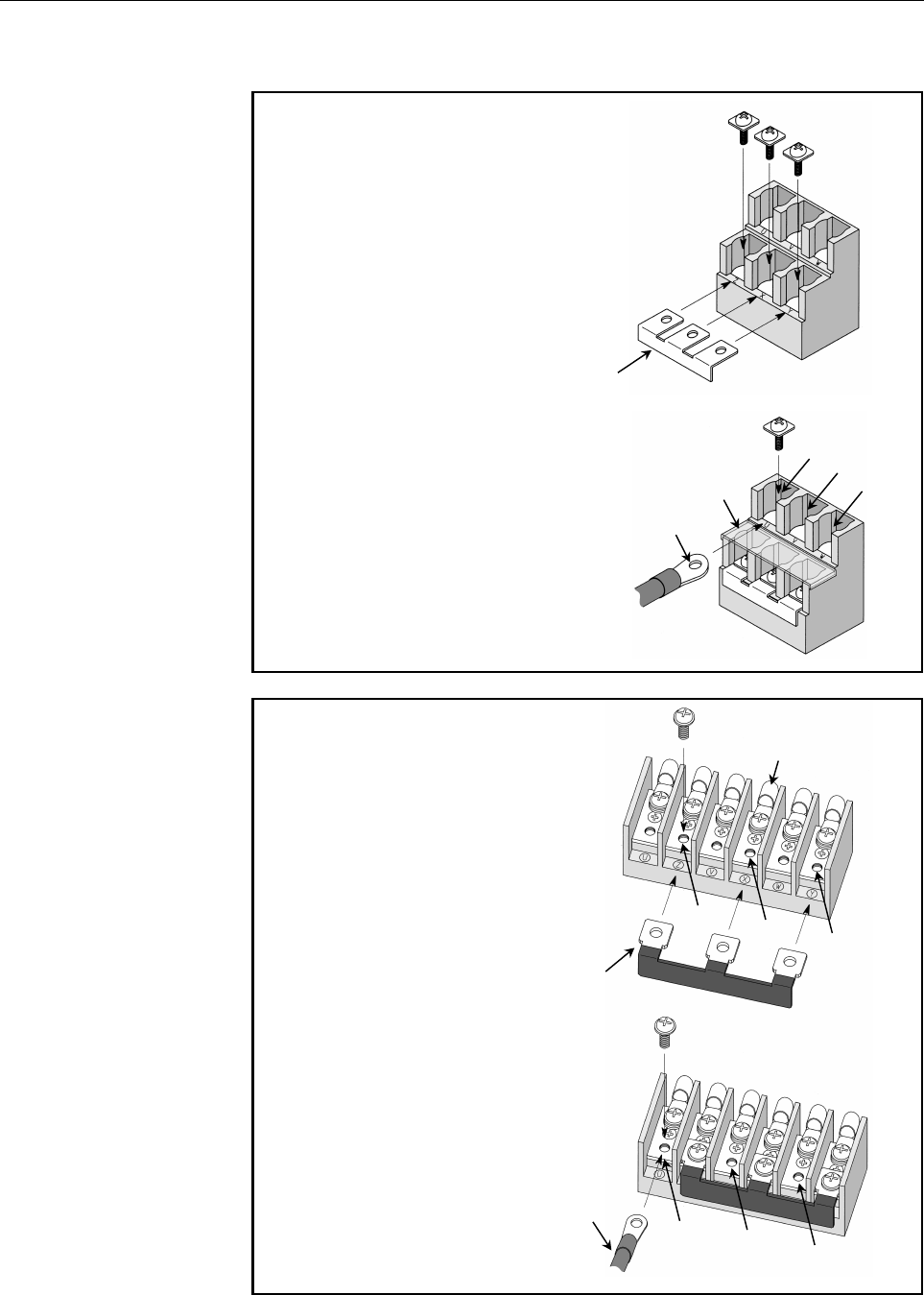
- Page 444.NOTES ON INSTALLATION SPECIFICATIONS FOR THE αi SERIES B-65272EN/04 2) Using the motor by energizing it only with the low-speed winding (Y connection) rather than switching its output • Connecting power leads to an M5 type terminal board <1> Mounting a jumper Mount a jumper on the lower row to mak
- Page 45B-65272EN/04 SPECIFICATIONS FOR THE αi SERIES 4.NOTES ON INSTALLATION 3) Using the motor by energizing it only with the high-speed winding (∆ connection) rather than switching its output • Connecting power leads to an M5 Jumper type terminal board (A65L-0001-0630/SD) <1> Mounting jumpers Mount three
- Page 464.NOTES ON INSTALLATION SPECIFICATIONS FOR THE αi SERIES B-65272EN/04 4.3 FAN MOTOR CONNECTION 50Hz 60Hz αi, αiP, αiT series Rated Rated Surge Rated Rated Surge spindle motor models voltage current current voltage current current [V] [A] [Ap-p] [V] [A] [Ap-p] α1i, α1.5i, α1.5iT 240 0.15 0.47 240 0.1
- Page 47B-65272EN/04 SPECIFICATIONS FOR THE αi SERIES 4.NOTES ON INSTALLATION Cable for the fan motor The machine tool builder is to prepare the following cable for the fan motor: Vinyl heavy-duty power cord JIS C 3312 3-conductor Conductor: 37/0.26 (2 mm2) Sheath: PVCφ11 Crimp terminal: T2-4S <1> For a non
- Page 484.NOTES ON INSTALLATION SPECIFICATIONS FOR THE αi SERIES B-65272EN/04 Method of connection to a non-screw terminal for the fan motor 8 to 9mm Peel-off length of a wire sheath By using an appropriate tool, peel off each wire sheath by 8 to 9 mm. Sheath Conductor Screwdriver Use a flat-blade screwdriv
- Page 49B-65272EN/04 SPECIFICATIONS FOR THE αi SERIES 4.NOTES ON INSTALLATION 4.4 WHEN A MOTOR IS CONNECTED TO A SPINDLE VIA A BELT CAUTION 1 Mounting the pulley - The gap between the inner surface of the motor pulley and output shaft should be 10µm to 15µm. - If the gap is large when the high-speed rotatio
- Page 504.NOTES ON INSTALLATION SPECIFICATIONS FOR THE αi SERIES B-65272EN/04 4 Limit the radial load applied to the motor output shaft by the tension of the belt to the allowable value described in the manual for each series. If the allowable value is exceeded, the bearing or shaft may fail prematurely. 5
- Page 51B-65272EN/04 SPECIFICATIONS FOR THE αi SERIES 4.NOTES ON INSTALLATION 6 Use an appropriate tension gage to tension the belt. Examples Sonic type: U-305 series manufactured by UNITTA. Mechanical type: BT-33-73F manufactured by KENT-MOORE of the United States A mechanical type tension gage may give a
- Page 524.NOTES ON INSTALLATION SPECIFICATIONS FOR THE αi SERIES B-65272EN/04 4.5 WHEN A MOTOR IS CONNECTED TO A SPINDLE VIA A GEAR CAUTION 1 Do not use a helical gear which applies a load in the motor axial direction. 2 To prevent unusual gear sounds, apply the following precautions: (1) The deviation of t
- Page 53B-65272EN/04 SPECIFICATIONS FOR THE αi SERIES 4.NOTES ON INSTALLATION 4.6 WHEN A MOTOR IS DIRECTLY CONNECTED TO A SPINDLE VIA A COUPLING CAUTION 1 Use a coupling which can absorb thermal expansion in the axial direction of the motor mating shaft so that no load is applied in the motor axial directio
- Page 545.NOTES ON OPERATION SPECIFICATIONS FOR THE αi SERIES B-65272EN/04 5 WARNING NOTES ON OPERATION 1 When supplying voltage to the spindle motor or the fan motor, ensure that the earth cable is connected to the earth terminal and secure that the spindle motor is put to earth certainly. CAUTION 1 After
- Page 55B-65272EN/04 SPECIFICATIONS FOR THE αi SERIES 6.DETERMINING THE ACCELERATION TIME 6 DETERMINING THE ACCELERATION TIME The time required for each acceleration for the acceleration/ deceleration output characteristics shown below can be obtained from the following equation. Since machine load torque i
- Page 566.DETERMINING THE ACCELERATION TIME SPECIFICATIONS FOR THE αi SERIES B-65272EN/04 - Acceleration time (t1) in the constant-torque range (0 to Nb) (JL+Jm) ×Nb2 t1=0.10754× [sec] Pf×1000 - Acceleration time (t2) in the constant-output range (Nb to Nf) (JL+Jm) × (Nf2-Nb2) t2=0.10754× [sec] 2×Pf×1000 -
- Page 57B-65272EN/04 SPECIFICATIONS FOR THE αi SERIES 6.DETERMINING THE ACCELERATION TIME Pf : 11×1.2=13.2 [kW] Pm : 7.5×1.2=9 [kW] Nb : 1500 [min-1] Nf : 6000 [min-1] Nm : 8000 [min-1] NOTE For all models, these are not guaranteed values but guidelines. In case of αCi series, use 30 min rated output for Pf
- Page 586.DETERMINING THE ACCELERATION TIME SPECIFICATIONS FOR THE αi SERIES B-65272EN/04 Reference 1 When a cylinder rotates about its center axis, its inertia can be obtained from the following equation. The inertia of a gear can be obtained in a similar way. Q [cm] L [cm] πγ J= Q4L [kgf⋅cm⋅sec2] 32×980 W
- Page 59B-65272EN/04 SPECIFICATIONS FOR THE αi SERIES 6.DETERMINING THE ACCELERATION TIME Reference 2 To obtain the value GD2 [kgf⋅m2] for cylinder, get the value of G from its weight in kilograms and use the following equation to get the value of D2. - Solid cylinder D0 [m] 2 D2=D0 /2 - Hollow cylinder D0
- Page 606.DETERMINING THE ACCELERATION TIME SPECIFICATIONS FOR THE αi SERIES B-65272EN/04 Reference 3 Note the following relationship between the value of inertia I [kg⋅m2] in SI units and the value of GD2 [kgf⋅m2]: I[kg⋅m2]=GD2 [kgf⋅m2]/4 Therefore, to convert I [kg⋅m2] to J [kgf⋅cm⋅sec2], use the followin
- Page 61B-65272EN/04 SPECIFICATIONS FOR THE αi SERIES 7.DETERMINING THE ALLOWABLE DUTY CYCLE 7 DETERMINING THE ALLOWABLE DUTY CYCLE When machining requires the spindle to accelerate and decelerate frequently, the average output per cycle must not exceed the continuous rated output.The allowable duty cycle f
- Page 627.DETERMINING THE ALLOWABLE DUTY CYCLE SPECIFICATIONS FOR THE αi SERIES B-65272EN/04 NOTE 1 Cutting output P3 at motor speed N which is lower than base speed Nb shall be calculated by the following equation. P3=PC × Nb/N [kW] (PC: Actual cutting output) 2 In case that P3 is calculated by the load in
- Page 63B-65272EN/04 SPECIFICATIONS FOR THE αi SERIES 7.DETERMINING THE ALLOWABLE DUTY CYCLE Allowable duty cycle time Dt for repeated acceleration/deceleration Motor output Passage of time t1 t4 Motor output P4 P1 P1 Passage 1 cycle time Dt of time 1 Dt= ×(P30min2×1.22) × (t1+t4) 2 P CONT Pcont : Continuou
- Page 648.DISPOSAL OF SPINDLE MOTORS BY MATERIAL TYPESPECIFICATIONS FOR THE αi SERIESB-65272EN/04 8 DISPOSAL OF SPINDLE MOTORS BY MATERIAL TYPE Disposal of motors by separating plastic parts from metal parts After a motor is dismantled, the plastic parts (terminal box, terminal box cover, fan cover) must be
- Page 65II. FANUC AC SPINDLE MOTOR αi SERIES
- Page 66
- Page 67B-65272EN/04 FANUC AC SPINDLE MOTOR αi SERIES 1.GENERAL 1 GENERAL The FANUC AC spindle motor αi series is ideal for CNC machine tool spindles. Features - The motor is compact, light-weight and furnished with digital control for much higher performance. - The motor inertia of the AC spindle motor is
- Page 682.SPECIFICATIONS FANUC AC SPINDLE MOTOR αi SERIES B-65272EN/04 2 SPECIFICATIONS - 46 -
- Page 69B-65272EN/04 FANUC AC SPINDLE MOTOR αi SERIES 2.SPECIFICATIONS Series αi series Model α0.5/10000i α1/10000i α1.5/10000i Item Cont. rated kW 0.55 1.5 1.1 (HP) (0.74) (2.0) (1.5) 30 min rated kW 1.1 2.2 3.7 Output [15 min, 10min] (*2) (*3) (HP) (1.5) (3.0) (5.0) S3 60% kW 1.1 2.2 3.7 [40%,25%] (*4)(*5
- Page 702.SPECIFICATIONS FANUC AC SPINDLE MOTOR αi SERIES B-65272EN/04 Series αi series Model α2/10000i α3/10000i α6/10000i α8/8000i Item Cont. rated kW 2.2 3.7 5.5 7.5 (HP) (3.0) (5.0) (7.4) (10) 30 min rated kW 3.7 5.5 7.5 11 Output [15 min, 10min] (*2) (*3) (HP) (5.0) (7.4) (10) (14.7) S3 60% kW 3.7 5.5
- Page 71B-65272EN/04 FANUC AC SPINDLE MOTOR αi SERIES 2.SPECIFICATIONS Series αi series Model α12/7000i α15/7000i α18/7000i α22/7000i Item Cont. rated kW 11 15 18.5 22 (HP) (14.7) (20.1) (24.8) (29.5) 30 min rated kW 15 18.5 22 26 Output [15 min, 10min] (*2) (*3) (HP) (20.1) (24.8) (29.5) (34.9) S3 60% kW 1
- Page 722.SPECIFICATIONS FANUC AC SPINDLE MOTOR αi SERIES B-65272EN/04 Series αi series Model α30/6000i α40/6000i α50/4500i Item Cont. rated kW 30 37 45 (HP) (40.2) (49.6) (60.3) 30 min rated kW 37 45 55 Output [15 min, 10min] (*2) (*3) (HP) (49.6) (60.3) (73.7) S3 60% kW 37 45 55 [40%,25%] (*4)(*5) (HP) (4
- Page 73B-65272EN/04 FANUC AC SPINDLE MOTOR αi SERIES 2.SPECIFICATIONS Series αi series Model α1/15000i α1.5/15000i α2/15000i α3/12000i Item Cont. rated kW 1.5 1.5 2.2 3.7 (HP) (2.0) (2.0) (3.0) (5.0) 30 min rated kW 2.2 2.2 3.7 5.5 Output [15 min, 10min] (*2) (*3) (HP) (3.0) (3.0) (5.0) (7.4) S3 60% kW 2.2
- Page 742.SPECIFICATIONS FANUC AC SPINDLE MOTOR αi SERIES B-65272EN/04 Series αi series α6/12000i(*1) α8/10000i(*1) Model Item Low-speed High-speed Low-speed High-speed winding winding winding winding Cont. rated kW 5.5 5.5 7.5 7.5 (HP) (7.4) (7.4) (10) (10) 30 min rated kW 7.5 7.5 11 11 Output [15 min, 10m
- Page 75B-65272EN/04 FANUC AC SPINDLE MOTOR αi SERIES 2.SPECIFICATIONS Series αi series α12/10000i(*1) α15/10000i(*1) Model Low-speed High-speed Low-speed High-speed Item winding winding winding winding Cont. rated kW 11 11 15 15 (HP) (14.7) (14.7) (20.1) (20.1) 30 min rated kW 15 15 18.5 18.5 Output [15 mi
- Page 762.SPECIFICATIONS FANUC AC SPINDLE MOTOR αi SERIES B-65272EN/04 Series αi series α18/10000i(*1) α22/10000i(*1) Model Low-speed High-speed Low-speed High-speed Item winding winding winding winding Cont. rated kW 18.5 18.5 22 22 (HP) (24.8) (24.8) (29.5) (29.5) 30 min rated kW 22 22 26 26 Output [15 mi
- Page 77B-65272EN/04 FANUC AC SPINDLE MOTOR αi SERIES 2.SPECIFICATIONS (*1) For α6/12000i, α8/10000i, α12/10000i, α15/10000i, α18/10000i, and α22/10000i, the CNC soft option and switching magnetic contactor unit associated with the output switch function (Y-∆ switch) are required. See FANUC SERVO AMPLIFIER
- Page 783.OUTPUT/TORQUE CHARACTERISTICS FANUC AC SPINDLE MOTOR αi SERIES B-65272EN/04 3 Reference OUTPUT/TORQUE CHARACTERISTICS Calculation for torque Torque T can be obtained by the following equation. T[N⋅m]=P[kW]×1000/0.1047/N[min-1] P[kW]: Motor output N[min-1]: Motor speed When the unit of T is [kgf⋅m]
- Page 79B-65272EN/04 FANUC AC SPINDLE MOTOR αi SERIES 3.OUTPUT/TORQUE CHARACTERISTICS 3.1 MODEL α0.5/10000i Output Torque [kW] [N⋅m] 1.6 4 15min, S3 40% Operating zone 1.2 1.1kW 3 15min, S3 40% 0.9kW 0.8 Operating zone 2 0.55kW 0.4 Continuous 1 0.37kW Continuous operating zone operating zone 3000 3000 0 0 0
- Page 803.OUTPUT/TORQUE CHARACTERISTICS FANUC AC SPINDLE MOTOR αi SERIES B-65272EN/04 3.3 MODEL α1.5/10000i Output Torque [kW] [N⋅m] 5 25 4 3.7kW 20 10min, S3 25% Operating zone 3 10min, S3 25% 15 Operating zone Continuous 2.2kW operating zone 2 10 1.1kW 1 0.9kW 5 Continuous 1500 operating zone 1500 0 0 0 2
- Page 81B-65272EN/04 FANUC AC SPINDLE MOTOR αi SERIES 3.OUTPUT/TORQUE CHARACTERISTICS 3.5 MODEL α3/10000i Output Torque [kW] [N⋅m] 8 40 30min, S3 60% 30min, S3 60% Operating zone Operating zone 6 5.5kW 30 Continuous 4 3.7kW 20 3.7kW operating zone Continuous operating zone 2.5kW 2 10 1500 7000 1500 0 0 0 20
- Page 823.OUTPUT/TORQUE CHARACTERISTICS FANUC AC SPINDLE MOTOR αi SERIES B-65272EN/04 3.7 MODEL α8/8000i Output Torque [kW] [N⋅m] 16 80 30min, S3 60% 30min, S3 60% Operating zone Operating zone 12 11kW 60 Continuous 7.5kW 8 40 operating zone 7.5kW Continuous 5.5kW 4 operating zone 20 1500 1500 0 0 0 2000 40
- Page 83B-65272EN/04 FANUC AC SPINDLE MOTOR αi SERIES 3.OUTPUT/TORQUE CHARACTERISTICS 3.9 MODEL α15/7000i Output Torque [kW] [N⋅m] 25 150 30min, S3 60% 30min, S3 60% Operating zone Operating zone 20 18.5kW 120 15kW 15 15kW 90 Continuous operating zone 11kW 10 60 Continuous operating zone 5 30 1500 7000 1500
- Page 843.OUTPUT/TORQUE CHARACTERISTICS FANUC AC SPINDLE MOTOR αi SERIES B-65272EN/04 3.11 MODEL α22/7000i Output Torque [kW] [N⋅m] 32 180 30min, S3 60%Operating zone 30min, S3 60% 26kW 150 Operating zone 24 22kW 22kW 120 18.5kW 16 90 Continuous operating zone 60 Continuous 8 operating zone 30 1500 7000 150
- Page 85B-65272EN/04 FANUC AC SPINDLE MOTOR αi SERIES 3.OUTPUT/TORQUE CHARACTERISTICS 3.13 MODEL α40/6000i Applicable amplifier SPM-45i Output Torque [kW] 30min, S3 60%Operating zone [N⋅m] 50 400 45kW 40 37kW 300 30min, S3 60% 30 30kW Operating zone 26kW 200 20 Continuous operating zone 100 10 Continuous op
- Page 863.OUTPUT/TORQUE CHARACTERISTICS FANUC AC SPINDLE MOTOR αi SERIES B-65272EN/04 3.15 MODEL α1/15000i Applicable amplifier SPM-5.5i Output Torque [kW] [N⋅m] 3 8 15min, S3 40% 2.5 Operating zone 2.2kW 6 2 15min, S3 40% Operating zone 1.5 4 Continuous operating zone 1 2 0.5 Continuous operating zone 0 0
- Page 87B-65272EN/04 FANUC AC SPINDLE MOTOR αi SERIES 3.OUTPUT/TORQUE CHARACTERISTICS 3.16 MODEL α1.5/15000i Applicable amplifier SPM-15i Output Torque [kW] [N⋅m] 3 8 15min, S3 40% 2.5 Operating zone 2.2kW 6 2 15min, S3 40% Operating zone 1.5 4 Continuous 1 operating zone 2 0.5 Continuous operating zone 0 0
- Page 883.OUTPUT/TORQUE CHARACTERISTICS FANUC AC SPINDLE MOTOR αi SERIES B-65272EN/04 3.17 MODEL α2/15000i Applicable amplifier SPM-22i Output Torque [kW] [N⋅m] 5 16 15min, S3 40% 4 3.7kW Operating zone 12 15min, S3 40% 3 Operating zone 2.2kW 8 2 Continuous operating zone 4 1 Continuous operating zone 0 0 0
- Page 89B-65272EN/04 FANUC AC SPINDLE MOTOR αi SERIES 3.OUTPUT/TORQUE CHARACTERISTICS 3.18 MODEL α3/12000i Applicable amplifier SPM-11i Output Torque [kW] [N⋅m] 8 40 30min, S3 60% Operating zone 6 30 5.5kW 30min, S3 60% Operating zone 4 3.7kW 20 Continuous operating zone 2 10 1500 1500 Continuous operating
- Page 903.OUTPUT/TORQUE CHARACTERISTICS FANUC AC SPINDLE MOTOR αi SERIES B-65272EN/04 3.19 MODEL α6/12000i Low-speed winding output (Y connection) Low-speed winding torque (Y connection) [kW] [N⋅m] 10 60 30min, S3 60% 30min, S3 60% Operating zone 50 8 7.5kW Operating zone 40 6 5.5kW 30 Continuous Continuous
- Page 91B-65272EN/04 FANUC AC SPINDLE MOTOR αi SERIES 3.OUTPUT/TORQUE CHARACTERISTICS 3.20 MODEL α8/10000i Low-speed winding output (Y connection) Low-speed winding torque (Y connection) [kW] [N⋅m] 16 80 30min, S3 60% 30min, S3 60% Operating zone Operating zone 12 11W 60 7.5kW 8 40 Continuous Continuous ope
- Page 923.OUTPUT/TORQUE CHARACTERISTICS FANUC AC SPINDLE MOTOR αi SERIES B-65272EN/04 3.21 MODEL α12/10000i Low-speed winding output (Y connection) Low-speed winding torque (Y connection) [kW] [N⋅m] 20 120 30min, S3 60% 30min, S3 60% Operating zone 100 Operating zone 15 80 11W 10 60 Continuous Continuous 7.
- Page 93B-65272EN/04 FANUC AC SPINDLE MOTOR αi SERIES 3.OUTPUT/TORQUE CHARACTERISTICS 3.22 MODEL α15/10000i Low-speed winding output (Y connection) Low-speed winding torque (Y connection) [kW] [N⋅m] 24 160 30min, S3 60% 30min, S3 60% 18.5kW Operating zone Operating zone 18 120 15kW 12 80 Continuous Continuo
- Page 943.OUTPUT/TORQUE CHARACTERISTICS FANUC AC SPINDLE MOTOR αi SERIES B-65272EN/04 3.23 MODEL α18/10000i Low-speed winding output (Y connection) Low-speed winding torque (Y connection) [kW] [N⋅m] 30 160 30min, S3 60% 30min, S3 60% Operating zone 24 22kW Operating zone 120 18.5kW 18 15kW 80 12 Continuous
- Page 95B-65272EN/04 FANUC AC SPINDLE MOTOR αi SERIES 3.OUTPUT/TORQUE CHARACTERISTICS 3.24 MODEL α22/10000i Low-speed winding output (Y connection) Low-speed winding torque (Y connection) [kW] [N⋅m] 36 200 30min, S3 60% 30min, S3 60% Operating zone 26kW Operating zone 27 150 22kW 18 18.5kW 100 Continuous 15
- Page 964.CONNECTIONS FANUC AC SPINDLE MOTOR αi SERIES B-65272EN/04 4 CONNECTIONS - 74 -
- Page 97B-65272EN/04 FANUC AC SPINDLE MOTOR αi SERIES 4.CONNECTIONS 4.1 MODEL α0.5/10000i The power lead and signal lead are connected with the connector. Use the shield cable for the connection. Refer to FANUC SERVO AMPLIFIER αi series DESCRIPTIONS (B-65282EN) for other respects in the connection. Signal l
- Page 984.CONNECTIONS FANUC AC SPINDLE MOTOR αi SERIES B-65272EN/04 Connection of signal lead - For type with Mi sensor Connector parts related to cable side Japan Aviation Electronics Industry specification THR1 JN1xS10SL1: Applicable sheath diameter φ5.7 to 7.3 THR2 JN1xS10SL2: Applicable sheath diameter
- Page 99B-65272EN/04 FANUC AC SPINDLE MOTOR αi SERIES 4.CONNECTIONS 4.2 MODELS α1/10000i TO α50/4500i Cables for power lead and fan motor are connected to the terminal block. Mi sensor or MZi sensor signal or thermistor signal use a connector manufactured by Tyco Electronics AMP. The connector housing and t
- Page 1004.CONNECTIONS FANUC AC SPINDLE MOTOR αi SERIES B-65272EN/04 4.3 CONNECTION OF SIGNAL LEAD Connector attachment for a motor with a built-in Mi sensor Connector pins arrangement THR1 Number B1 B2 B3 B4 B5 B6 THR2 Color +5V 0V Signal RA RB 0V THR2 PA PB Number A1 A2 A3 A4 A5 A6 RA RB Color SS Signal +5
- Page 101B-65272EN/04 FANUC AC SPINDLE MOTOR αi SERIES 5.ALLOWABLE RADIAL LOAD 5 ALLOWABLE RADIAL LOAD Use the motor output shaft below the allowable radial loads shown in the table below. Allowable radial load (kgf) Model At output shaft At output shaft end center α0.5/10000i 294N (30kgf) 323N (33kgf) α1/10
- Page 1026.ASSEMBLING ACCURACYFANUC AC SPINDLE MOTOR αi SERIES B-65272EN/04 6 ASSEMBLING ACCURACY Model α1/15000i to α0.5i to α22i α30i to α50i Measuring method Item α2/15000i 1/2 the output shaft length Run-out at the end of the 20µm or less 20µm or less 10µm or less output shaft Run-out of the faucet joint
- Page 103B-65272EN/04 FANUC AC SPINDLE MOTOR αi SERIES 7.EXTERNAL DIMENSIONS 7 EXTERNAL DIMENSIONS Model name Section Model α0.5/10000i (flange mounting type) 7.1 Models α1/10000i and α1/15000i (flange mounting type) 7.2 Model α1/10000i (foot mounting type) 7.3 Model α1.5/10000i (flange mounting type) 7.4 Mo
- Page 1047.EXTERNAL DIMENSIONS FANUC AC SPINDLE MOTOR αi SERIES B-65272EN/04 7.1 MODEL α0.5/10000i (FLANGE MOUNTING TYPE) - 82 -
- Page 105B-65272EN/04 FANUC AC SPINDLE MOTOR αi SERIES 7.EXTERNAL DIMENSIONS 7.2 MODELS α1/10000i AND α1/15000i (FLANGE MOUNTING TYPE) - 83 -
- Page 1067.EXTERNAL DIMENSIONS FANUC AC SPINDLE MOTOR αi SERIES B-65272EN/04 7.3 MODEL α1/10000i (FOOT MOUNTING TYPE) - 84 -
- Page 107B-65272EN/04 FANUC AC SPINDLE MOTOR αi SERIES 7.EXTERNAL DIMENSIONS 7.4 MODEL α1.5/10000i (FLANGE MOUNTING TYPE) - 85 -
- Page 1087.EXTERNAL DIMENSIONS FANUC AC SPINDLE MOTOR αi SERIES B-65272EN/04 7.5 MODEL α1.5/15000i (FLANGE MOUNTING TYPE) - 86 -
- Page 109B-65272EN/04 FANUC AC SPINDLE MOTOR αi SERIES 7.EXTERNAL DIMENSIONS 7.6 MODEL α1.5/10000i (FOOT MOUNTING TYPE) - 87 -
- Page 1107.EXTERNAL DIMENSIONS FANUC AC SPINDLE MOTOR αi SERIES B-65272EN/04 7.7 MODEL α2/10000i (FLANGE MOUNTING TYPE) - 88 -
- Page 111B-65272EN/04 FANUC AC SPINDLE MOTOR αi SERIES 7.EXTERNAL DIMENSIONS 7.8 MODEL α2/15000i (FLANGE MOUNTING TYPE) - 89 -
- Page 1127.EXTERNAL DIMENSIONS FANUC AC SPINDLE MOTOR αi SERIES B-65272EN/04 7.9 MODEL α2/10000i (FOOT MOUNTING TYPE) - 90 -
- Page 113B-65272EN/04 FANUC AC SPINDLE MOTOR αi SERIES 7.EXTERNAL DIMENSIONS 7.10 MODELS α3/10000i AND α3/12000i (FLANGE MOUNTING TYPE) - 91 -
- Page 1147.EXTERNAL DIMENSIONS FANUC AC SPINDLE MOTOR αi SERIES B-65272EN/04 7.11 MODEL α3/10000i (FOOT MOUNTING TYPE) - 92 -
- Page 115B-65272EN/04 FANUC AC SPINDLE MOTOR αi SERIES 7.EXTERNAL DIMENSIONS 7.12 MODELS α6/10000i AND α6/12000i (FLANGE MOUNTING TYPE) - 93 -
- Page 1167.EXTERNAL DIMENSIONS FANUC AC SPINDLE MOTOR αi SERIES B-65272EN/04 7.13 MODEL α6/10000i (FOOT MOUNTING TYPE) - 94 -
- Page 117B-65272EN/04 FANUC AC SPINDLE MOTOR αi SERIES 7.EXTERNAL DIMENSIONS 7.14 MODELS α8/8000i AND α8/10000i (FLANGE MOUNTING TYPE) - 95 -
- Page 1187.EXTERNAL DIMENSIONS FANUC AC SPINDLE MOTOR αi SERIES B-65272EN/04 7.15 MODEL α8/8000i (FOOT MOUNTING TYPE) - 96 -
- Page 119B-65272EN/04 FANUC AC SPINDLE MOTOR αi SERIES 7.EXTERNAL DIMENSIONS 7.16 MODELS α12/7000i AND α12/10000i (FLANGE MOUNTING TYPE) - 97 -
- Page 1207.EXTERNAL DIMENSIONS FANUC AC SPINDLE MOTOR αi SERIES B-65272EN/04 7.17 MODEL α12/7000i (FOOT MOUNTING TYPE) - 98 -
- Page 121B-65272EN/04 FANUC AC SPINDLE MOTOR αi SERIES 7.EXTERNAL DIMENSIONS 7.18 MODELS α15/7000i AND α15/10000i (FLANGE MOUNTING TYPE) - 99 -
- Page 1227.EXTERNAL DIMENSIONS FANUC AC SPINDLE MOTOR αi SERIES B-65272EN/04 7.19 MODEL α15/7000i (FOOT MOUNTING TYPE) - 100 -
- Page 123B-65272EN/04 FANUC AC SPINDLE MOTOR αi SERIES 7.EXTERNAL DIMENSIONS 7.20 MODELS α18/7000i AND α18/10000i (FLANGE MOUNTING TYPE) - 101 -
- Page 1247.EXTERNAL DIMENSIONS FANUC AC SPINDLE MOTOR αi SERIES B-65272EN/04 7.21 MODEL α18/7000i (FOOT MOUNTING TYPE) - 102 -
- Page 125B-65272EN/04 FANUC AC SPINDLE MOTOR αi SERIES 7.EXTERNAL DIMENSIONS 7.22 MODELS α22/7000i AND α22/10000i (FLANGE MOUNTING TYPE) - 103 -
- Page 1267.EXTERNAL DIMENSIONS FANUC AC SPINDLE MOTOR αi SERIES B-65272EN/04 7.23 MODEL α22/7000i (FOOT MOUNTING TYPE) - 104 -
- Page 127B-65272EN/04 FANUC AC SPINDLE MOTOR αi SERIES 7.EXTERNAL DIMENSIONS 7.24 MODEL α30/6000i (FLANGE MOUNTING TYPE) - 105 -
- Page 1287.EXTERNAL DIMENSIONS FANUC AC SPINDLE MOTOR αi SERIES B-65272EN/04 7.25 MODEL α30/6000i (FOOT MOUNTING TYPE) - 106 -
- Page 129B-65272EN/04 FANUC AC SPINDLE MOTOR αi SERIES 7.EXTERNAL DIMENSIONS 7.26 MODEL α40/6000i (FLANGE MOUNTING TYPE) - 107 -
- Page 1307.EXTERNAL DIMENSIONS FANUC AC SPINDLE MOTOR αi SERIES B-65272EN/04 7.27 MODEL α40/6000i (FOOT MOUNTING TYPE) - 108 -
- Page 131B-65272EN/04 FANUC AC SPINDLE MOTOR αi SERIES 7.EXTERNAL DIMENSIONS 7.28 MODEL α50/4500i (FLANGE MOUNTING TYPE) - 109 -
- Page 1327.EXTERNAL DIMENSIONS FANUC AC SPINDLE MOTOR αi SERIES B-65272EN/04 7.29 MODEL α50/4500i (FOOT MOUNTING TYPE) - 110 -
- Page 133III. FANUC AC SPINDLE MOTOR αiP SERIES
- Page 134
- Page 135B-65272EN/04 FANUC AC SPINDLE MOTOR αiP SERIES 1.GENERAL 1 GENERAL FANUC AC spindle motor αiP series is suitable for structural simplification by eliminating the machine spindle gear box. Features - As the rated output range is wide from 1:10 to 1:16 , a gear box structure for speed change is not re
- Page 1362.SPECIFICATIONS FANUC AC SPINDLE MOTOR αiP SERIES B-65272EN/04 2 SPECIFICATIONS - 114 -
- Page 137B-65272EN/04 FANUC AC SPINDLE MOTOR αiP SERIES 2.SPECIFICATIONS Series αiP series α12/6000iP α15/6000iP Model α12/8000iP α15/8000iP Item Low-speed High-speed Low-speed High-speed winding winding winding winding Cont. rated kW 3.7 5.5 5 7.5 (HP) (4.9) (7.4) (6.6) (10) 30 min rated kW 7.5 7.5 9 9 Outp
- Page 1382.SPECIFICATIONS FANUC AC SPINDLE MOTOR αiP SERIES B-65272EN/04 Series αiP series α18/6000iP α22/6000iP Model α18/8000iP α22/8000iP Item Low-speed High-speed Low-speed High-speed winding winding winding winding Cont. rated kW 6 9 7.5 11 (HP) (8) (12) (10) (14.7) 30 min rated kW 11 11 15 15 Output [1
- Page 139B-65272EN/04 FANUC AC SPINDLE MOTOR αiP SERIES 2.SPECIFICATIONS Series αiP series α30/6000iP α40/6000iP Model Low-speed High-speed Low-speed High-speed Item winding winding winding winding Cont. rated kW 11 15 13 18.5 (HP) (14.7) (20.1) (17.3) (24.8) 30 min rated kW 18.5 18.5 22 22 Output [15 min] (
- Page 1402.SPECIFICATIONS FANUC AC SPINDLE MOTOR αiP SERIES B-65272EN/04 Series αiP series α50/6000iP α60/4500iP Model Low-speed High-speed Low-speed High-speed Item winding winding winding winding Cont. rated kW 22 22 18.5 22 (HP) (29.5) (29.5) (24.8) (29.5) 30 min rated kW 30 30 30 30 Output [15 min] (*2)
- Page 141B-65272EN/04 FANUC AC SPINDLE MOTOR αiP SERIES 2.SPECIFICATIONS (*1) When the output switch function is used, the CNC soft option and switching magnetic contactor unit associated with the output switch function (Y-∆ switch) are required. See FANUC SERVO AMPLIFIER αi series DESCRIPTIONS (B-65282EN) f
- Page 1423.OUTPUT/TORQUE CHARACTERISTICSFANUC AC SPINDLE MOTOR αiP SERIES B-65272EN/04 3 Reference OUTPUT/TORQUE CHARACTERISTICS Calculation for torque Torque T can be obtained by the following equation. T[N⋅m]=P[kW]×1000/0.1047/N[min-1] P[kW]: Motor output N[min-1]: Motor speed When the unit of T is [kgf⋅m]
- Page 143B-65272EN/04 FANUC AC SPINDLE MOTOR αiP SERIES3.OUTPUT/TORQUE CHARACTERISTICS 3.1 MODEL α12/6000iP Low-speed winding output (Y connection) Low-speed winding torque (Y connection) [kW] [N⋅m] 10 160 7.5kW 15min, S3 15% 8 120 Operating zone 15min, S3 15% 6 Operating zone 80 3.7W 4 Continuous operating
- Page 1443.OUTPUT/TORQUE CHARACTERISTICSFANUC AC SPINDLE MOTOR αiP SERIES B-65272EN/04 3.2 MODEL α15/6000iP Low-speed winding output (Y connection) Low-speed winding torque (Y connection) [kW] [N⋅m] 12 250 9kW 200 15min, S3 15% Operating zone 8 15min, S3 15% Operating zone 150 5kW 100 4 Continuous operating
- Page 145B-65272EN/04 FANUC AC SPINDLE MOTOR αiP SERIES3.OUTPUT/TORQUE CHARACTERISTICS 3.3 MODEL α18/6000iP Low-speed winding output (Y connection) Low-speed winding torque (Y connection) [kW] [N⋅m] 16 250 200 15min, S3 15% 12 11kW Operating zone 15min, S3 15% 150 Operating zone 8 6kW 100 Continuous 4 operat
- Page 1463.OUTPUT/TORQUE CHARACTERISTICSFANUC AC SPINDLE MOTOR αiP SERIES B-65272EN/04 3.4 MODEL α22/6000iP Low-speed winding output (Y connection) Low-speed winding torque (Y connection) [kW] [N⋅m] 20 320 15min, S3 15% 15 240 Operating zone 15min, S3 15% Operating zone 10 160 7.5kW Continuous 5 operating zo
- Page 147B-65272EN/04 FANUC AC SPINDLE MOTOR αiP SERIES3.OUTPUT/TORQUE CHARACTERISTICS 3.5 MODEL α30/6000iP Low-speed winding output (Y connection) Low-speed winding torque (Y connection) [kW] [Nm] 24 500 18.5kW 15min, S3 15% 400 18 Operating zone 15min, S3 15% Operating zone 300 12 11KW 11KW 200 Continuous
- Page 1483.OUTPUT/TORQUE CHARACTERISTICSFANUC AC SPINDLE MOTOR αiP SERIES B-65272EN/04 3.6 MODEL α40/6000iP Low-speed winding output (Y connection) Low-speed winding torque (Y connection) [kW] [Nm] 30 600 24 22kW 480 15min, S3 15% Operating zone 15min, S3 15% 18 18.5KW 360 Operating zone 12 13KW 240 11KW Con
- Page 149B-65272EN/04 FANUC AC SPINDLE MOTOR αiP SERIES3.OUTPUT/TORQUE CHARACTERISTICS 3.7 MODEL α50/6000iP Low-speed winding output (Y connection) Low-speed winding torque (Y connection) [kW] [N⋅m] 40 600 30min, S3 25% Operating zone 480 30min, S3 25% 30 Operating zone 26kW 22KW 360 20 Continuous operating
- Page 1503.OUTPUT/TORQUE CHARACTERISTICSFANUC AC SPINDLE MOTOR αiP SERIES B-65272EN/04 3.8 MODEL α60/4500iP Low-speed winding output (Y connection) Low-speed winding torque (Y connection) [kW] [N⋅m] 40 800 30min, S3 25% 30kW Operating zone 30min, S3 25% 30 600 Operating zone 18.5KW 20 400 17kW 13kW 10 200 Co
- Page 151B-65272EN/04 FANUC AC SPINDLE MOTOR αiP SERIES3.OUTPUT/TORQUE CHARACTERISTICS 3.9 MODEL α12/8000iP Low-speed winding output (Y connection) Low-speed winding torque (Y connection) [kW] [N⋅m] 10 160 7.5kW 15min, S3 15% 8 120 Operating zone 15min, S3 15% 6 Operating zone 80 3.7W 4 Continuous operating
- Page 1523.OUTPUT/TORQUE CHARACTERISTICSFANUC AC SPINDLE MOTOR αiP SERIES B-65272EN/04 3.10 MODEL α15/8000iP Low-speed winding output (Y connection) Low-speed winding torque (Y connection) [kW] [N⋅m] 12 250 9kW 200 15min, S3 15% Operating zone 8 15min, S3 15% Operating zone 150 5kW 100 4 Continuous operating
- Page 153B-65272EN/04 FANUC AC SPINDLE MOTOR αiP SERIES3.OUTPUT/TORQUE CHARACTERISTICS 3.11 MODEL α18/8000iP Low-speed winding output (Y connection) Low-speed winding torque (Y connection) [kW] [N⋅m] 16 250 15min, S3 15% Operating zone 15min, S3 15% 200 12 11kW Operating zone 150 8 6kW 100 Continuous 4 opera
- Page 1543.OUTPUT/TORQUE CHARACTERISTICSFANUC AC SPINDLE MOTOR αiP SERIES B-65272EN/04 3.12 MODEL α22/8000iP Low-speed winding output (Y connection) Low-speed winding torque (Y connection) [kW] [N⋅m] 20 320 15min, S3 15% 15 240 Operating zone 15min, S3 15% Operating zone 10 160 7.5kW 5 80 Continuous Continuo
- Page 155B-65272EN/04 FANUC AC SPINDLE MOTOR αiP SERIES 4.CONNECTIONS 4 CONNECTIONS - 133 -
- Page 1564.CONNECTIONS FANUC AC SPINDLE MOTOR αiP SERIES B-65272EN/04 4.1 MODELS α12/6000iP TO α60/4500iP Cables for power lead and fan motor are connected to the terminal block. Mi sensor or MZi sensor signal or thermo stat signal use a connector manufactured by Tyco Electronics AMP. The connector housing a
- Page 157B-65272EN/04 FANUC AC SPINDLE MOTOR αiP SERIES 4.CONNECTIONS 4.2 CONNECTION OF SIGNAL LEAD Connector attachment for a motor with a built-in Mi sensor Connector pins arrangement THR1 Number B1 B2 B3 B4 B5 B6 THR2 Color +5V 0V Signal RA RB 0V THR2 PA PB Number A1 A2 A3 A4 A5 A6 RA RB Color SS Signal +
- Page 1585.ALLOWABLE RADIAL LOAD FANUC AC SPINDLE MOTOR αiP SERIES B-65272EN/04 5 ALLOWABLE RADIAL LOAD Use the motor output shaft below the allowable radial loads shown in the table below. Allowable radial load (kgf) Model At output shaft At output shaft end center α12/6000iP, α15/6000iP 2940N (300kgf) 3410
- Page 159B-65272EN/04 FANUC AC SPINDLE MOTOR αiP SERIES 6.ASSEMBLING ACCURACY 6 ASSEMBLING ACCURACY Model α12iP to α22iP α30iP to α60iP Measuring method Item 1/2 the output shaft length Run-out at the end of the output 20µm or less 20µm or less shaft Run-out of the faucet joint for mounting the flange agains
- Page 1607.EXTERNAL DIMENSIONS FANUC AC SPINDLE MOTOR αiP SERIES B-65272EN/04 7 EXTERNAL DIMENSIONS Model name Section Models α12/6000iP and α12/8000iP (flange mounting type) 7.1 Model α12/6000iP (foot mounting type) 7.2 Models α15/6000iP and α15/8000iP (flange mounting type) 7.3 Model α15/6000iP (foot mount
- Page 161B-65272EN/04 FANUC AC SPINDLE MOTOR αiP SERIES 7.EXTERNAL DIMENSIONS 7.1 MODELS α12/6000iP AND α12/8000iP (FRANGE MOUNTING TYPE) - 139 -
- Page 1627.EXTERNAL DIMENSIONS FANUC AC SPINDLE MOTOR αiP SERIES B-65272EN/04 7.2 MODEL α12/6000iP (FOOT MOUNTING TYPE) - 140 -
- Page 163B-65272EN/04 FANUC AC SPINDLE MOTOR αiP SERIES 7.EXTERNAL DIMENSIONS 7.3 MODELS α15/6000iP AND α15/8000iP (FRANGE MOUNTING TYPE) - 141 -
- Page 1647.EXTERNAL DIMENSIONS FANUC AC SPINDLE MOTOR αiP SERIES B-65272EN/04 7.4 MODEL α15/6000iP (FOOT MOUNTING TYPE) - 142 -
- Page 165B-65272EN/04 FANUC AC SPINDLE MOTOR αiP SERIES 7.EXTERNAL DIMENSIONS 7.5 MODELS α18/6000iP AND α18/8000iP (FRANGE MOUNTING TYPE) - 143 -
- Page 1667.EXTERNAL DIMENSIONS FANUC AC SPINDLE MOTOR αiP SERIES B-65272EN/04 7.6 MODEL α18/6000iP (FOOT MOUNTING TYPE) - 144 -
- Page 167B-65272EN/04 FANUC AC SPINDLE MOTOR αiP SERIES 7.EXTERNAL DIMENSIONS 7.7 MODELS α22/6000iP AND α22/8000iP (FRANGE MOUNTING TYPE) - 145 -
- Page 1687.EXTERNAL DIMENSIONS FANUC AC SPINDLE MOTOR αiP SERIES B-65272EN/04 7.8 MODEL α22/6000iP (FOOT MOUNTING TYPE) - 146 -
- Page 169B-65272EN/04 FANUC AC SPINDLE MOTOR αiP SERIES 7.EXTERNAL DIMENSIONS 7.9 MODELS α30/6000iP AND α40/6000iP (FRANGE MOUNTING TYPE) - 147 -
- Page 1707.EXTERNAL DIMENSIONS FANUC AC SPINDLE MOTOR αiP SERIES B-65272EN/04 7.10 MODELS α30/6000iP AND α40/6000iP (FOOT MOUNTING TYPE) - 148 -
- Page 171B-65272EN/04 FANUC AC SPINDLE MOTOR αiP SERIES 7.EXTERNAL DIMENSIONS 7.11 MODEL α50/6000iP (FRANGE MOUNTING TYPE) - 149 -
- Page 1727.EXTERNAL DIMENSIONS FANUC AC SPINDLE MOTOR αiP SERIES B-65272EN/04 7.12 MODEL α50/6000iP (FOOT MOUNTING TYPE) - 150 -
- Page 173B-65272EN/04 FANUC AC SPINDLE MOTOR αiP SERIES 7.EXTERNAL DIMENSIONS 7.13 MODEL α60/4500iP (FRANGE MOUNTING TYPE) - 151 -
- Page 1747.EXTERNAL DIMENSIONS FANUC AC SPINDLE MOTOR αiP SERIES B-65272EN/04 7.14 MODEL α60/4500iP (FOOT MOUNTING TYPE) - 152 -
- Page 175IV. FANUC AC SPINDLE MOTOR αiT SERIES
- Page 176
- Page 177B-65272EN/04 FANUC AC SPINDLE MOTOR αiT SERIES 1.GENERAL 1 Features GENERAL By directly connecting the spindle with a spindle motor (hollow shaft), higher-speed spindle rotation and highly efficient center-through coolant machining are enabled. A spindle of direct motor connection type is connected
- Page 1781.GENERAL FANUC AC SPINDLE MOTOR αiT SERIES B-65272EN/04 Important (1) For attachment of this type of motor to a spindle, only coupling- based direct connection with the spindle is allowed. When a spindle of direct motor connection type is used, fretting can occur with the motor shaft in a short-tim
- Page 179B-65272EN/04 FANUC AC SPINDLE MOTOR αiT SERIES 2.SPECIFICATIONS 2 SPECIFICATIONS - 157 -
- Page 1802.SPECIFICATIONS FANUC AC SPINDLE MOTOR αiT SERIES B-65272EN/04 Model α1.5/15000iT α2/15000iT α3/12000iT Item (S1)Cont. rated kW 1.5 2.2 3.7 (HP) (2.0) (3.0) (5.0) Output (S2)30 min rated kW 2.2 3.7 5.5 (*1) [15 min](*2)(HP) (3.0) (5.0) (7.4) (S3)60%[40%]kW 2.2 3.7 5.5 (*3) (*4) (HP) (3.0) (5.0) (7.
- Page 181B-65272EN/04 FANUC AC SPINDLE MOTOR αiT SERIES 2.SPECIFICATIONS Model α6/12000iT α8/12000iT Item Low-speed winding High-speed winding Low-speed winding High-speed winding Connection (*13) (Y connection) (∆ connection) (Y connection) (∆ connection) (S1)Cont. rated kW 5.5 5.5 7.5 7.5 (HP) (7.4) (7.4)
- Page 1822.SPECIFICATIONS FANUC AC SPINDLE MOTOR αiT SERIES B-65272EN/04 Model α8/15000iT α15/10000iT Item Low-speed winding High-speed winding Low-speed winding High-speed winding Connection (*13) (Y connection) (∆ connection) (Y connection) (∆ connection) (S1)Cont. rated kW 7.5 7.5 15 15 (HP) (10) (10) (20
- Page 183B-65272EN/04 FANUC AC SPINDLE MOTOR αiT SERIES 2.SPECIFICATIONS Model α15/12000iT α22/10000iT Item Low-speed winding High-speed winding Low-speed winding High-speed winding Connection (*13) (Y connection) (Y connection) (Y connection) (∆ connection) (S1)Cont. rated kW 15 15 22 22 (HP) (20.1) (20.1)
- Page 1842.SPECIFICATIONS FANUC AC SPINDLE MOTOR αiT SERIES B-65272EN/04 Cautions and limitations (*1) The rated output is guaranteed at the rated voltage. (Amplifier input: 200 to 230VAC) If the input voltage fluctuates, it is possible that the rated output cannot be obtained even when such fluctuations are
- Page 185B-65272EN/04 FANUC AC SPINDLE MOTOR αiT SERIES3.OUTPUT/TORQUE CHARACTERISTICS 3 Reference OUTPUT/TORQUE CHARACTERISTICS Calculation for torque Torque T can be obtained by the following equation. T[N⋅m]=P[kW]×1000/0.1047/N[min-1] P[kW]: Motor output N[min-1]: Motor speed When the unit of T is [kgf⋅m]
- Page 1863.OUTPUT/TORQUE CHARACTERISTICSFANUC AC SPINDLE MOTOR αiT SERIES B-65272EN/04 3.1 MODEL α1.5/15000iT Applicable amplifier SPM-15i Output Torque [kW] [N⋅m] 2.5 10 2.2kW 15min, S3 40% 2 8 15min, S3 40% Operating zone Operating zone 1.5 1.5kW 6 1 4 Continuous operating zone 0.5 2 Continuous operating z
- Page 187B-65272EN/04 FANUC AC SPINDLE MOTOR αiT SERIES3.OUTPUT/TORQUE CHARACTERISTICS 3.2 MODEL α2/15000iT Applicable amplifier SPM-22i Output Torque [kW] [N⋅m] 5 15 4 15min, S3 40% 12 3.7kW Operating zone 15min, S3 40% 3 9 Operating zone 2 2.2kW 6 Continuous operating zone 1 3 Continuous operating zone 0 0
- Page 1883.OUTPUT/TORQUE CHARACTERISTICSFANUC AC SPINDLE MOTOR αiT SERIES B-65272EN/04 3.3 MODEL α3/12000iT Applicable amplifier SPM-11i Output Torque [kW] [N⋅m] 8 40 30min, S3 60% 6 30 5.5kW Operating zone 30min, S3 60% Operating zone 4 3.7kW 20 Continuous operating zone 2 10 1500 1500 Continuous operating
- Page 189B-65272EN/04 FANUC AC SPINDLE MOTOR αiT SERIES3.OUTPUT/TORQUE CHARACTERISTICS 3.4 MODEL α6/12000iT Applicable amplifier SPM-15i Low-speed winding output (Y connection) Low-speed winding torque (Y connection) [kW] [N⋅m] 15 50 13kW (Maximum output during acceleration) 30min, S3 60% Operating zone 12 4
- Page 1903.OUTPUT/TORQUE CHARACTERISTICSFANUC AC SPINDLE MOTOR αiT SERIES B-65272EN/04 3.5 MODEL α8/12000iT Applicable amplifier SPM-15i Low-speed winding output (Y connection) Low-speed winding torque (Y connection) [kW] [N⋅m] 16 80 30min, S3 60% Operating zone 12 11kW 60 30min, S3 60% Operating zone 8 40 7
- Page 191B-65272EN/04 FANUC AC SPINDLE MOTOR αiT SERIES3.OUTPUT/TORQUE CHARACTERISTICS 3.6 MODEL α8/15000iT Applicable amplifier SPM-26i Low-speed winding output (Y connection) Low-speed winding torque (Y connection) [kW] [N⋅m] 20 120 10 min operating zone 15 90 30 min 15kW 10 min operating zone operating zo
- Page 1923.OUTPUT/TORQUE CHARACTERISTICSFANUC AC SPINDLE MOTOR αiT SERIES B-65272EN/04 3.7 MODEL α15/10000iT Applicable amplifier SPM-22i Low-speed winding output (Y connection) Low-speed winding torque (Y connection) [kW] [N⋅m] 30 160 30min, S3 60% Operating zone 30min, S3 60% Operating zone 24 120 18.5kW 1
- Page 193B-65272EN/04 FANUC AC SPINDLE MOTOR αiT SERIES3.OUTPUT/TORQUE CHARACTERISTICS 3.8 MODEL α15/12000iT Applicable amplifier SPM-30i Low-speed winding output (Y connection) Low-speed winding torque (Y connection) [kW] [N⋅m] 30 200 15 min 15 min operating zone 30 min operating zone 25 operating zone 22kW
- Page 1943.OUTPUT/TORQUE CHARACTERISTICSFANUC AC SPINDLE MOTOR αiT SERIES B-65272EN/04 3.9 MODEL α22/10000iT Applicable amplifier SPM-26i Low-speed winding output (Y connection) Low-speed winding torque (Y connection) [kW] [N⋅m] 40 200 30min, S3 40% 30min, S3 40% Operating zone Operating zone 30 150 26kW 22k
- Page 195B-65272EN/04 FANUC AC SPINDLE MOTOR αiT SERIES 4.CONFIGURATION AND ORDERING NUMBER 4 CONFIGURATION AND ORDERING NUMBER - 173 -
- Page 1964.CONFIGURATION AND ORDERING NUMBER FANUC AC SPINDLE MOTOR αiT SERIES B-65272EN/04 4.1 CONFIGURATION The αiT series motor consists of the following items: (1) Main spindle motor unit (2) Fan motor (Exhaust on the side opposite to the load axis. Packed separately.) (3) Connector (housing, contact) fo
- Page 197B-65272EN/04 FANUC AC SPINDLE MOTOR αiT SERIES 4.CONFIGURATION AND ORDERING NUMBER 4.2 ORDERING NUMBER Motor (including a cooling fan) Model Ordering number SPM Remarks α1.5/15000iT A06B-1463-B123#0021 SPM-15i α2/15000iT A06B-1464-B123#0021 SPM-22i - Flange mounting α3/12000iT A06B-1465-B123#0021 SP
- Page 1985.CONNECTIONS FANUC AC SPINDLE MOTOR αiT SERIES B-65272EN/04 5 CONNECTIONS - 176 -
- Page 199B-65272EN/04 FANUC AC SPINDLE MOTOR αiT SERIES 5.CONNECTIONS 5.1 CONNECTION OF THE POWER, FAN MOTOR, AND MZi SENSOR SIGNAL LEADS Cables for power lead and fan motor are connected to the terminal block. MZi sensor signal or thermo stat signal use a connector manufactured by Tyco Electronics AMP. The
- Page 2005.CONNECTIONS FANUC AC SPINDLE MOTOR αiT SERIES B-65272EN/04 Cable for the fan motor For the fan motor current value and cable specifications, refer to Section I.4.3, “FAN MOTOR CONNECTION” in this manual. - 178 -
- Page 201B-65272EN/04 FANUC AC SPINDLE MOTOR αiT SERIES 5.CONNECTIONS 5.2 CONNECTION OF SIGNAL LEAD MZi sensor signal or overheat signal use a connector manufactured by Tyco Electronics AMP. The connector housing and the connector are attached to the motor. TH R1 Connector pins arrangement TH R2 + 5V Number
- Page 2026.ASSEMBLING ACCURACY FANUC AC SPINDLE MOTOR αiT SERIES B-65272EN/04 6 Item ASSEMBLING ACCURACY Accuracy Measuring method 1/2 the output shaft length Run-out at the end of the output shaft 10µm or less Run-out of the faucet joint for mounting the flange against the core 30µm or less 10 of the shaft
- Page 203B-65272EN/04 FANUC AC SPINDLE MOTOR αiT SERIES 7.EXTERNAL DIMENSIONS 7 EXTERNAL DIMENSIONS Model name Section Model α1.5/15000iT 7.1 Model α2/15000iT 7.2 Model α3/12000iT 7.3 Model α6/12000iT 7.4 Models α8/12000iT and α8/15000iT 7.5 Model α15/10000iT 7.6 Model α15/12000iT 7.7 Model α22/10000iT 7.8 D
- Page 2047.EXTERNAL DIMENSIONS FANUC AC SPINDLE MOTOR αiT SERIES B-65272EN/04 7.1 MODEL α1.5/15000iT - 182 -
- Page 205B-65272EN/04 FANUC AC SPINDLE MOTOR αiT SERIES 7.EXTERNAL DIMENSIONS 7.2 MODEL α2/15000iT - 183 -
- Page 2067.EXTERNAL DIMENSIONS FANUC AC SPINDLE MOTOR αiT SERIES B-65272EN/04 7.3 MODEL α3/12000iT - 184 -
- Page 207B-65272EN/04 FANUC AC SPINDLE MOTOR αiT SERIES 7.EXTERNAL DIMENSIONS 7.4 MODEL α6/12000iT - 185 -
- Page 2087.EXTERNAL DIMENSIONS FANUC AC SPINDLE MOTOR αiT SERIES B-65272EN/04 7.5 MODELS α8/12000iT AND α8/15000iT - 186 -
- Page 209B-65272EN/04 FANUC AC SPINDLE MOTOR αiT SERIES 7.EXTERNAL DIMENSIONS 7.6 MODEL α15/10000iT - 187 -
- Page 2107.EXTERNAL DIMENSIONS FANUC AC SPINDLE MOTOR αiT SERIES B-65272EN/04 7.7 MODEL α15/12000iT - 188 -
- Page 211B-65272EN/04 FANUC AC SPINDLE MOTOR αiT SERIES 7.EXTERNAL DIMENSIONS 7.8 MODEL α22/10000iT - 189 -
- Page 2127.EXTERNAL DIMENSIONS FANUC AC SPINDLE MOTOR αiT SERIES B-65272EN/04 7.9 DISTANCE BLOCK TYPE 1.5iT - 190 -
- Page 213B-65272EN/04 FANUC AC SPINDLE MOTOR αiT SERIES 7.EXTERNAL DIMENSIONS 7.10 DISTANCE BLOCK TYPE 2iT - 191 -
- Page 2147.EXTERNAL DIMENSIONS FANUC AC SPINDLE MOTOR αiT SERIES B-65272EN/04 7.11 DISTANCE BLOCK TYPE 6iT - 192 -
- Page 215B-65272EN/04 FANUC AC SPINDLE MOTOR αiT SERIES 7.EXTERNAL DIMENSIONS 7.12 DISTANCE BLOCK TYPE 15iT - 193 -
- Page 2168.POINTS ABOUT DIRECT CONNECTION STRUCTUREFANUC AC SPINDLE MOTOR αiT SERIES B-65272EN/04 8 POINTS ABOUT DIRECT CONNECTION STRUCTURE If the motor shaft and spindle are not centered precisely when the spindle motor is directly connected to the spindle, fretting can occur with the motor shaft in a shor
- Page 217B-65272EN/04 FANUC AC SPINDLE MOTOR αiT SERIES 9.NOTES ON MOTOR INSTALLATION 9 NOTES ON MOTOR INSTALLATION - 195 -
- Page 2189.NOTES ON MOTOR INSTALLATION FANUC AC SPINDLE MOTOR αiT SERIES B-65272EN/04 9.1 HIGHER-PRECISION MOUNTING FLANGE AND SHAFT With the αiT series, a mounting flange and shaft are assembled with higher precision for direct connection with the spindle. For details, see Chapter 6, "ASSEMBLY PRECISION". -
- Page 219B-65272EN/04 FANUC AC SPINDLE MOTOR αiT SERIES 9.NOTES ON MOTOR INSTALLATION 9.2 CENTERING USING CENTERING PLATES When connecting the spindle with the motor shaft, make centering with a target concentricity of 5µm. If centering accuracy measurement is difficult, it is recommended to use centering pl
- Page 2209.NOTES ON MOTOR INSTALLATION FANUC AC SPINDLE MOTOR αiT SERIES B-65272EN/04 9.3 CHECKING MOTOR VIBRATION (TO SEE WHETHER CENTERING IS SUCCESSFUL) To check whether the spindle is centered with the motor successfully, measure the vibration acceleration of the motor. Center the motor shaft with the sp
- Page 221B-65272EN/04 FANUC AC SPINDLE MOTOR αiT SERIES 9.NOTES ON MOTOR INSTALLATION 9.4 COUPLING SELECTION Select a coupling that does not apply a thrust load onto the motor shaft for a cause such as coolant pressure when the temperature rises or cutting is performed. When attaching a coupling to the motor
- Page 2229.NOTES ON MOTOR INSTALLATION FANUC AC SPINDLE MOTOR αiT SERIES B-65272EN/04 (Example of an air vent on a gear coupling) O-ring Air vent (Reference) Contact points for couplings Type of Point of Applicable Manufacturer coupling contact maximum speed (*) -1 EAGLE INDUSTRY CO., LTD Diaphragm 03-3438-1
- Page 223B-65272EN/04 FANUC AC SPINDLE MOTOR αiT SERIES 9.NOTES ON MOTOR INSTALLATION L t φd L Motor shaft SPANN ELEMENTE RINGFEDER The models α1.5/15000iT and α2/15000iT have a less thickness (t). ↓ 2 [Stress applied to motor shaft] ≤ [Motor shaft yield point (490 N/mm )] α6/12000iT α8/12000iT α1.5/15000iT
- Page 2249.NOTES ON MOTOR INSTALLATION FANUC AC SPINDLE MOTOR αiT SERIES B-65272EN/04 9.5 ROTATION JOINT When coolant is flown through the through hole of the motor shaft, a coolant pressure acts on the end face of the coolant joint attached to the shaft front end, thus producing a thrust load that pushes th
- Page 225B-65272EN/04 FANUC AC SPINDLE MOTOR αiT SERIES 9.NOTES ON MOTOR INSTALLATION 9.6 COOLANT JOINT The machine tool builder is to prepare the following coolant joint: Shaft tip screw Motor shaft (Deublin) φd φ12.9 φ6 A Coolant joint B (Figure of coolant joint) Convex type Concave type φd φd <1> When spi
- Page 2269.NOTES ON MOTOR INSTALLATION FANUC AC SPINDLE MOTOR αiT SERIES B-65272EN/04 * Before attaching a coolant joint, apply screw locking adhesive. Be sure to use a motor shaft tip screw when attaching a coolant joint. <3> Method of calculating a thrust load imposed on the motor when a coolant pressure o
- Page 227B-65272EN/04 FANUC AC SPINDLE MOTOR αiT SERIES 9.NOTES ON MOTOR INSTALLATION 9.7 ROTATION JOINT SUPPORT HOUSING The machine tool builder is to prepare a rotation joint support housing. To secure a housing, use a socket and spigot joint and six M5 tapped holes at the motor rear end. Prepare six M5 bo
- Page 228
- Page 229V. FANUC AC SPINDLE MOTOR αiL SERIES
- Page 230
- Page 231B-65272EN/04 FANUC AC SPINDLE MOTOR αiL SERIES 1.GENERAL 1 GENERAL The FANUC AC spindle motor αiL series is liquid-cooled motors. They feature low temperature rise, high-speed, high torque at low speed, and low vibration. Coupling an αiL series motor directly to the spindle of a machining center mak
- Page 2322.SPECIFICATIONS FANUC AC SPINDLE MOTOR αiL SERIES B-65272EN/04 2 SPECIFICATIONS - 210 -
- Page 233B-65272EN/04 FANUC AC SPINDLE MOTOR αiL SERIES 2.SPECIFICATIONS Model α8/20000iL α15/15000iL α26/15000iL Item Low-speed High-speed Low-speed High-speed Low-speed High-speed Connection (*1) winding (Y winding (Y winding (Y winding (Y winding (Y winding (Y connection) connection) connection) connectio
- Page 2342.SPECIFICATIONS FANUC AC SPINDLE MOTOR αiL SERIES B-65272EN/04 Cautions and limitations (*1) The power wire switching method is Y-Y switching. Refer to FANUC SERVO AMPLIFIER αi series DESCRIPTIONS (B- 65282EN) for explanations about output switching control. (*2) The rated output is guaranteed at t
- Page 235B-65272EN/04 FANUC AC SPINDLE MOTOR αiL SERIES 3.OUTPUT/TORQUE CHARACTERISTICS 3 Reference OUTPUT/TORQUE CHARACTERISTICS Calculation for torque Torque T can be obtained by the following equation. T[N⋅m]=P[kW]×1000/0.1047/N[min-1] P[kW]: Motor output N[min-1]: Motor speed When the unit of T is [kgf⋅m
- Page 2363.OUTPUT/TORQUE CHARACTERISTICS FANUC AC SPINDLE MOTOR αiL SERIES B-65272EN/04 3.1 MODEL α8/20000iL Applicable amplifier SPM-30i Cooler capacity 2.9kW (2500kcal/h) Low-speed winding output (Y connection) Low-speed winding torque (Y connection) [kW] [N⋅m] 30 150 S3 25% Operating zone S3 25% Operating
- Page 237B-65272EN/04 FANUC AC SPINDLE MOTOR αiL SERIES 3.OUTPUT/TORQUE CHARACTERISTICS 3.2 MODEL α15/15000iL Applicable amplifier SPM-30i Cooler capacity 3.5kW (3000kcal/h) Low-speed winding output (Y connection) Low-speed winding torque (Y connection) [kW] [N⋅m] 40 200 15 min 15 min operating zone operatin
- Page 2383.OUTPUT/TORQUE CHARACTERISTICS FANUC AC SPINDLE MOTOR αiL SERIES B-65272EN/04 3.3 MODEL α26/15000iL Applicable amplifier SPM-30i Cooler capacity 4.1kW (3500kcal/h) Low-speed winding output (Y connection) Low-speed winding torque (Y connection) [kW] [N⋅m] 30 400 S3 15% S3 40% S3 40% Operating zone O
- Page 239B-65272EN/04 FANUC AC SPINDLE MOTOR αiL SERIES 4.CONNECTIONS 4 CONNECTIONS - 217 -
- Page 2404.CONNECTIONS FANUC AC SPINDLE MOTOR αiL SERIES B-65272EN/04 4.1 TOTAL CONNECTION DIAGRAM Switching unit CNC JA7BA +24V RYS(8) RELAY SOCKET(5) 200 VAC, single phase MCC1(42) Spindle Magnetic contactor for power wire amplifier switching PMC module(SPMi) MCC2 U U2 U U2 V V2 V V2 W W W W2 PE G MCC1 AC
- Page 241B-65272EN/04 FANUC AC SPINDLE MOTOR αiL SERIES 4.CONNECTIONS 4.2 SIZE OF POWER LEAD When connecting power wires to the amplifier, switching unit, and motor, use the wire size and crimp terminal listed below or equivalents. Applicable power lead size Crimp terminal size 2 (mm ) Motor model (*2) Ampli
- Page 2424.CONNECTIONS FANUC AC SPINDLE MOTOR αiL SERIES B-65272EN/04 4.3 CONNECTION OF SIGNAL LEAD MZi sensor signal or overheat signal use a connector manufactured by Tyco Electronics AMP. The connector housing and the connector are attached to the motor. THR1 Connector pins arrangement THR2 Number B1 B2 B
- Page 243B-65272EN/04 FANUC AC SPINDLE MOTOR αiL SERIES 4.CONNECTIONS 4.4 COOLING Cooling conditions Item α8/20000iL α15/15000iL α26/15000iL (*1) (*1) (*1) kw 2.3 to 3.5 2.9 to 3.5 2.9 to 4.1 Cooler capacity (kcal/h) (2000 to 3000) (2500 to 3000) (2500 to 3500) 1. Liquid Liquid coolant (*2) 2. Liquid additiv
- Page 2444.CONNECTIONS FANUC AC SPINDLE MOTOR αiL SERIES B-65272EN/04 Liquid coolant piping This motor series needs cooling based on liquid coolant. - Factory-setting The motor comes with rubber blocks for pipe protection. The machine tool builder is requested to prepare a pipe block according to the followi
- Page 245B-65272EN/04 FANUC AC SPINDLE MOTOR αiL series 5.ASSEMBLING ACCURACY 5 Item ASSEMBLING ACCURACY Accuracy Measuring method 1/2 the output shaft length Run-out at the end of the output shaft 10µm or less Run-out of the faucet joint for mounting 10 30µm or less the flange against the core of the shaft
- Page 2466.EXTERNAL DIMENSIONSFANUC AC SPINDLE MOTOR αiL SERIES B-65272EN/04 6 EXTERNAL DIMENSIONS Model name Section Model α8/20000iL 6.1 Model α15/15000iL 6.2 Model α26/15000iL 6.3 - 224 -
- Page 247B-65272EN/04 FANUC AC SPINDLE MOTOR αiL SERIES6.EXTERNAL DIMENSIONS 6.1 MODEL α8/20000iL - 225 -
- Page 2486.EXTERNAL DIMENSIONSFANUC AC SPINDLE MOTOR αiL SERIES B-65272EN/04 6.2 MODEL α15/15000iL - 226 -
- Page 249B-65272EN/04 FANUC AC SPINDLE MOTOR αiL SERIES6.EXTERNAL DIMENSIONS 6.3 MODEL α26/15000iL - 227 -
- Page 250
- Page 251VI. FANUC AC SPINDLE MOTOR α(HV)i SERIES
- Page 252
- Page 253B-65272EN/04 FANUC AC SPINDLE MOTOR α(HV)i SERIES 1.GENERAL 1 GENERAL The FANUC AC Spindle Motor α(HV)i series includes standard spindle motors for CNC machine tool spindles, which can be driven by 400 to 480VAC without a step-down transformer(*1). (*1) For models α1HVi, α1.5HVi, α2HVi, and α3HVi, h
- Page 2542.SPECIFICATIONS FANUC AC SPINDLE MOTOR α(HV)i SERIES B-65272EN/04 2 SPECIFICATIONS - 232 -
- Page 255B-65272EN/04 FANUC AC SPINDLE MOTOR α(HV)i SERIES 2.SPECIFICATIONS Series α(HV)i series Model α0.5/10000HVi α1/10000HVi α1.5/10000HVi Item Cont. rated kW 0.55 1.5 1.1 (HP) (0.74) (2.0) (1.5) 30 min rated kW 1.1 2.2 3.7 Output [15 min, 10min] (*2) (*3) (HP) (1.5) (3.0) (5.0) S3 60% kW 1.1 2.2 3.7 [40
- Page 2562.SPECIFICATIONS FANUC AC SPINDLE MOTOR α(HV)i SERIES B-65272EN/04 Series α(HV)i series Model α2/10000HVi α3/10000HVi α6/10000HVi α8/8000HVi Item Cont. rated kW 2.2 3.7 5.5 7.5 (HP) (3.0) (5.0) (7.4) (10) 30 min rated kW 3.7 5.5 7.5 11 Output [15 min, 10min] (*2) (*3) (HP) (5.0) (7.4) (10) (14.7) S3
- Page 257B-65272EN/04 FANUC AC SPINDLE MOTOR α(HV)i SERIES 2.SPECIFICATIONS Series α(HV)i series Model α12/7000HVi α15/7000HVi α22/7000HVi α30/6000HVi Item Cont. rated kW 11 15 22 30 (HP) (14.7) (20.1) (29.5) (40.2) 30 min rated kW 15 18.5 26 37 Output [15 min, 10min] (*2) (*3) (HP) (20.1) (24.8) (34.9) (49.
- Page 2582.SPECIFICATIONS FANUC AC SPINDLE MOTOR α(HV)i SERIES B-65272EN/04 Series α(HV)i series α100/4500HVi (*1) Model α40/6000HVi α60/4500HVi Low-speed High-speed Item winding winding Cont. rated kW 37 60 100 100 (HP) (49.6) (80.4) (134.0) (134.0) 30 min rated kW 45 75 Output [15 min, 10min] - - (*2) (*3)
- Page 259B-65272EN/04 FANUC AC SPINDLE MOTOR α(HV)i SERIES 2.SPECIFICATIONS (*1) For α100/4000HVi, the CNC soft option and switching magnetic contactor unit associated with the output switch function (Y-∆ switch) are required. See FANUC SERVO AMPLIFIER αi series DESCRIPTIONS (B-65282EN) for details of the ou
- Page 2603.OUTPUT/TORQUE CHARACTERISTICS FANUC AC SPINDLE MOTOR α(HV)i SERIES B-65272EN/04 3 Reference OUTPUT/TORQUE CHARACTERISTICS Calculation for torque Torque T can be obtained by the following equation. T[N⋅m]=P[kW]×1000/0.1047/N[min-1] P[kW]: Motor output N[min-1]: Motor speed When the unit of T is [kg
- Page 261B-65272EN/04 FANUC AC SPINDLE MOTOR α(HV)i SERIES 3.OUTPUT/TORQUE CHARACTERISTICS 3.1 MODEL α0.5/10000HVi Applicable amplifier SPM-5.5HVi Output Torque [kW] [N⋅m] 1.6 4 15min, S3 40% Operating zone 1.2 1.1kW 3 15min, S3 40% 0.9kW 0.8 Operating zone 2 0.55kW 0.4 Continuous 1 0.37kW Continuous operati
- Page 2623.OUTPUT/TORQUE CHARACTERISTICS FANUC AC SPINDLE MOTOR α(HV)i SERIES B-65272EN/04 3.3 MODEL α1.5/10000HVi Applicable amplifier SPM-5.5HVi Output Torque [kW] [N⋅m] 5 25 4 3.7kW 20 10min, S3 25% Operating zone 3 10min, S3 25% 15 Operating zone Continuous 2.2kW operating zone 2 10 1.1kW 1 0.9kW 5 Conti
- Page 263B-65272EN/04 FANUC AC SPINDLE MOTOR α(HV)i SERIES 3.OUTPUT/TORQUE CHARACTERISTICS 3.5 MODEL α3/10000HVi Applicable amplifier SPM-5.5HVi Output Torque [kW] [N⋅m] 8 40 30min, S3 60% 30min, S3 60% Operating zone Operating zone 6 5.5kW 30 Continuous 4 3.7kW 20 3.7kW operating zone Continuous operating z
- Page 2643.OUTPUT/TORQUE CHARACTERISTICS FANUC AC SPINDLE MOTOR α(HV)i SERIES B-65272EN/04 3.7 MODEL α8/8000HVi Applicable amplifier SPM-11HVi Output Torque [kW] [N⋅m] 16 80 30min, S3 60% 30min, S3 60% Operating zone Operating zone 12 11kW 60 7.5kW 8 40 7.5kW Continuous 5.5kW operating zone 4 20 Continuous o
- Page 265B-65272EN/04 FANUC AC SPINDLE MOTOR α(HV)i SERIES 3.OUTPUT/TORQUE CHARACTERISTICS 3.9 MODEL α15/7000HVi Applicable amplifier SPM-30HVi Output Torque [kW] [N⋅m] 25 150 30min, S3 60% 30min, S3 60% Operating zone Operating zone 20 18.5kW 120 15kW 15 15kW 90 Continuous 11kW operating zone 10 60 Continuo
- Page 2663.OUTPUT/TORQUE CHARACTERISTICS FANUC AC SPINDLE MOTOR α(HV)i SERIES B-65272EN/04 3.11 MODEL α30/6000HVi Applicable amplifier SPM-45HVi Output Torque [kW] [N⋅m] 50 400 30min, S3 40%Operating zone 30min, S3 40% 40 37kW Operating zone 300 30kW 30 200 Continuous 22kW 20 operating zone 18.5kW 100 Contin
- Page 267B-65272EN/04 FANUC AC SPINDLE MOTOR α(HV)i SERIES 3.OUTPUT/TORQUE CHARACTERISTICS 3.13 MODEL α60/4500HVi Applicable amplifier SPM-75HVi Output Torque [kW] [N⋅m] 100 800 30min, S3 40%Operating zone 30min, S3 40% Operating zone 80 75kW 600 120min 60kW 60 Operating zone Continuous 55kW operating zone 4
- Page 2683.OUTPUT/TORQUE CHARACTERISTICS FANUC AC SPINDLE MOTOR α(HV)i SERIES B-65272EN/04 3.14 MODEL α100/4000HVi Applicable amplifier SPM-75HVi Low-speed winding output (Y connection) Low-speed winding torque (Y connection) [kW] [N⋅m] 120 1200 100kW 100 1000 80 800 60 60kW 600 Continuous operating zone 40
- Page 269B-65272EN/04 FANUC AC SPINDLE MOTOR α(HV)i SERIES 4.CONNECTIONS 4 CONNECTIONS - 247 -
- Page 2704.CONNECTIONS FANUC AC SPINDLE MOTOR α(HV)i SERIES B-65272EN/04 4.1 MODEL α0.5/10000HVi The power lead and signal lead are connected with the connector. Use the shield cable for the connection. Refer to FANUC SERVO AMPLIFIER αi series DESCRIPTIONS (B-65282EN) for other respects in the connection. Si
- Page 271B-65272EN/04 FANUC AC SPINDLE MOTOR α(HV)i SERIES 4.CONNECTIONS Connection of signal lead - For type with Mi sensor Connector parts related to cable side Japan Aviation Electronics Industry specification THR1 JN1xS10SL1: Applicable sheath diameter φ5.7 to 7.3 THR2 JN1xS10SL2: Applicable sheath diame
- Page 2724.CONNECTIONS FANUC AC SPINDLE MOTOR α(HV)i SERIES B-65272EN/04 4.2 MODELS α1/10000HVi TO α100/4000HVi Cables of primary winding and fan motor are connected to the terminal block. Mi sensor or MZi sensor signal or thermistor signal use a connector manufactured by Tyco Electronics AMP. The connector
- Page 273B-65272EN/04 FANUC AC SPINDLE MOTOR α(HV)i SERIES 4.CONNECTIONS 4.3 CONNECTION OF SIGNAL LEAD Connector attachment for a motor with a built-in Mi sensor Connector pins arrangement THR1 Number B1 B2 B3 B4 B5 B6 THR2 Color +5V 0V Signal RA RB 0V THR2 PA PB Number A1 A2 A3 A4 A5 A6 RA RB Color SS Signa
- Page 2745.ALLOWABLE RADIAL LOADFANUC AC SPINDLE MOTOR α(HV)i SERIES B-65272EN/04 5 ALLOWABLE RADIAL LOAD Use the motor output shaft below the allowable radial loads shown in the table below. Allowable radial load (kgf) Model At output shaft At output shaft end center α0.5/10000HVi 294N (30kgf) 323N (33kgf)
- Page 275B-65272EN/04 FANUC AC SPINDLE MOTOR α(HV)i SERIES 6.ASSEMBLING ACCURACY 6 ASSEMBLING ACCURACY Model α0.5HVi to α30HVi to α100HVi Measuring method Item α22HVi α60HVi 1/2 the output shaft length Run-out at the end of the 20µm or less 20µm or less 40µm or less output shaft Run-out of the faucet joint f
- Page 2767.EXTERNAL DIMENSIONS FANUC AC SPINDLE MOTOR α(HV)i SERIES B-65272EN/04 7 EXTERNAL DIMENSIONS Model name Section Model α0.5/10000HVi (flange mounting type) 7.1 Model α1/10000HVi (flange mounting type) 7.2 Model α1/10000HVi (foot mounting type) 7.3 Model α1.5/10000HVi (flange mounting type) 7.4 Model
- Page 277B-65272EN/04 FANUC AC SPINDLE MOTOR α(HV)i SERIES 7.EXTERNAL DIMENSIONS 7.1 MODEL α0.5/10000HVi (FLANGE MOUNTING TYPE) - 255 -
- Page 2787.EXTERNAL DIMENSIONS FANUC AC SPINDLE MOTOR α(HV)i SERIES B-65272EN/04 7.2 MODEL α1/10000HVi (FLANGE MOUNTING TYPE) - 256 -
- Page 279B-65272EN/04 FANUC AC SPINDLE MOTOR α(HV)i SERIES 7.EXTERNAL DIMENSIONS 7.3 MODEL α1/10000HVi (FOOT MOUNTING TYPE) - 257 -
- Page 2807.EXTERNAL DIMENSIONS FANUC AC SPINDLE MOTOR α(HV)i SERIES B-65272EN/04 7.4 MODEL α1.5/10000HVi (FLANGE MOUNTING TYPE) - 258 -
- Page 281B-65272EN/04 FANUC AC SPINDLE MOTOR α(HV)i SERIES 7.EXTERNAL DIMENSIONS 7.5 MODEL α1.5/10000HVi (FOOT MOUNTING TYPE) - 259 -
- Page 2827.EXTERNAL DIMENSIONS FANUC AC SPINDLE MOTOR α(HV)i SERIES B-65272EN/04 7.6 MODEL α2/10000HVi (FLANGE MOUNTING TYPE) - 260 -
- Page 283B-65272EN/04 FANUC AC SPINDLE MOTOR α(HV)i SERIES 7.EXTERNAL DIMENSIONS 7.7 MODEL α2/10000HVi (FOOT MOUNTING TYPE) - 261 -
- Page 2847.EXTERNAL DIMENSIONS FANUC AC SPINDLE MOTOR α(HV)i SERIES B-65272EN/04 7.8 MODEL α3/10000HVi (FLANGE MOUNTING TYPE) - 262 -
- Page 285B-65272EN/04 FANUC AC SPINDLE MOTOR α(HV)i SERIES 7.EXTERNAL DIMENSIONS 7.9 MODEL α3/10000HVi (FOOT MOUNTING TYPE) - 263 -
- Page 2867.EXTERNAL DIMENSIONS FANUC AC SPINDLE MOTOR α(HV)i SERIES B-65272EN/04 7.10 MODEL α6/10000HVi (FLANGE MOUNTING TYPE) - 264 -
- Page 287B-65272EN/04 FANUC AC SPINDLE MOTOR α(HV)i SERIES 7.EXTERNAL DIMENSIONS 7.11 MODEL α6/10000HVi (FOOT MOUNTING TYPE) - 265 -
- Page 2887.EXTERNAL DIMENSIONS FANUC AC SPINDLE MOTOR α(HV)i SERIES B-65272EN/04 7.12 MODEL α8/8000HVi (FLANGE MOUNTING TYPE) - 266 -
- Page 289B-65272EN/04 FANUC AC SPINDLE MOTOR α(HV)i SERIES 7.EXTERNAL DIMENSIONS 7.13 MODEL α8/8000HVi (FOOT MOUNTING TYPE) - 267 -
- Page 2907.EXTERNAL DIMENSIONS FANUC AC SPINDLE MOTOR α(HV)i SERIES B-65272EN/04 7.14 MODEL α12/7000HVi (FLANGE MOUNTING TYPE) - 268 -
- Page 291B-65272EN/04 FANUC AC SPINDLE MOTOR α(HV)i SERIES 7.EXTERNAL DIMENSIONS 7.15 MODEL α12/7000HVi (FOOT MOUNTING TYPE) - 269 -
- Page 2927.EXTERNAL DIMENSIONS FANUC AC SPINDLE MOTOR α(HV)i SERIES B-65272EN/04 7.16 MODEL α15/7000HVi (FLANGE MOUNTING TYPE) - 270 -
- Page 293B-65272EN/04 FANUC AC SPINDLE MOTOR α(HV)i SERIES 7.EXTERNAL DIMENSIONS 7.17 MODEL α15/7000HVi (FOOT MOUNTING TYPE) - 271 -
- Page 2947.EXTERNAL DIMENSIONS FANUC AC SPINDLE MOTOR α(HV)i SERIES B-65272EN/04 7.18 MODEL α22/7000HVi (FLANGE MOUNTING TYPE) - 272 -
- Page 295B-65272EN/04 FANUC AC SPINDLE MOTOR α(HV)i SERIES 7.EXTERNAL DIMENSIONS 7.19 MODEL α22/7000HVi (FOOT MOUNTING TYPE) - 273 -
- Page 2967.EXTERNAL DIMENSIONS FANUC AC SPINDLE MOTOR α(HV)i SERIES B-65272EN/04 7.20 MODEL α30/6000HVi (FLANGE MOUNTING TYPE) - 274 -
- Page 297B-65272EN/04 FANUC AC SPINDLE MOTOR α(HV)i SERIES 7.EXTERNAL DIMENSIONS 7.21 MODEL α30/6000HVi (FOOT MOUNTING TYPE) - 275 -
- Page 2987.EXTERNAL DIMENSIONS FANUC AC SPINDLE MOTOR α(HV)i SERIES B-65272EN/04 7.22 MODEL α40/6000HVi (FLANGE MOUNTING TYPE) - 276 -
- Page 299B-65272EN/04 FANUC AC SPINDLE MOTOR α(HV)i SERIES 7.EXTERNAL DIMENSIONS 7.23 MODEL α40/6000HVi (FOOT MOUNTING TYPE) - 277 -
- Page 3007.EXTERNAL DIMENSIONS FANUC AC SPINDLE MOTOR α(HV)i SERIES B-65272EN/04 7.24 MODEL α60/4500HVi (FLANGE MOUNTING TYPE) - 278 -
- Page 301B-65272EN/04 FANUC AC SPINDLE MOTOR α(HV)i SERIES 7.EXTERNAL DIMENSIONS 7.25 MODEL α60/4500HVi (FOOT MOUNTING TYPE) - 279 -
- Page 3027.EXTERNAL DIMENSIONS FANUC AC SPINDLE MOTOR α(HV)i SERIES B-65272EN/04 7.26 MODEL α100/4000HVi (FOOT FLANGE MOUNTING TYPE) - 280 -
- Page 303VII. FANUC AC SPINDLE MOTOR α(HV)iP SERIES
- Page 304
- Page 305B-65272EN/04 FANUC AC SPINDLE MOTOR α(HV)iP SERIES 1.GENERAL 1 GENERAL FANUC AC spindle motor α(HV)iP series is suitable for structural simplification by eliminating the machine spindle gear box. Features - As the rated output range is wide from 1:10 to 1:16 , a gear box structure for speed change i
- Page 3062.SPECIFICATIONS FANUC AC SPINDLE MOTOR α(HV)iP SERIES B-65272EN/04 2 SPECIFICATIONS - 284 -
- Page 307B-65272EN/04 FANUC AC SPINDLE MOTOR α(HV)iP SERIES 2.SPECIFICATIONS Series α(HV)iP series α15/6000HViP α22/6000HViP Model Low-speed High-speed Low-speed High-speed Item winding winding winding winding Cont. rated kW 5 7.5 7.5 11 (HP) (6.6) (10) (10) (14.7) 30 min rated kW 9 9 15 15 Output [15 min] (
- Page 3082.SPECIFICATIONS FANUC AC SPINDLE MOTOR α(HV)iP SERIES B-65272EN/04 Series α(HV)iP series α40/6000HViP α50/6000HViP Model Low-speed High-speed Low-speed High-speed Item winding winding winding winding Cont. rated kW 13 18.5 22 22 (HP) (17.3) (24.8) (29.5) (29.5) 30 min rated kW 22 22 30 30 Output [1
- Page 309B-65272EN/04 FANUC AC SPINDLE MOTOR α(HV)iP SERIES 2.SPECIFICATIONS Series α(HV)iP series Model α60/4500HViP Item Low-speed winding High-speed winding Cont. rated kW 18.5 22 (HP) (24.8) (29.5) 30 min rated kW 30 30 Output [15 min] (*2) (*3) (HP) (40.2) (40.2) S3 60% kW 30 30 [15%] (*4)(*5) (HP) (40.
- Page 3102.SPECIFICATIONS FANUC AC SPINDLE MOTOR α(HV)iP SERIES B-65272EN/04 (*1) When the output switch function is used, the CNC soft option and switching magnetic contactor unit associated with the output switch function (Y-∆ switch) are required. See FANUC SERVO AMPLIFIER αi series DESCRIPTIONS (B-65282E
- Page 311B-65272EN/04 FANUC AC SPINDLE MOTOR α(HV)iP SERIES 3.OUTPUT/TORQUE CHARACTERISTICS 3 Reference OUTPUT/TORQUE CHARACTERISTICS Calculation for torque Torque T can be obtained by the following equation. T[N⋅m]=P[kW]×1000/0.1047/N[min-1] P[kW]: Motor output N[min-1]: Motor speed When the unit of T is [k
- Page 3123.OUTPUT/TORQUE CHARACTERISTICS FANUC AC SPINDLE MOTOR α(HV)iP SERIES B-65272EN/04 3.1 MODEL α15/6000HViP Applicable amplifier SPM-15HVi Low-speed winding output (Y connection) Low-speed winding torque (Y connection) [kW] [N⋅m] 12 250 9kW 200 15min, S3 15% Operating zone 8 15min, S3 15% Operating zo
- Page 313B-65272EN/04 FANUC AC SPINDLE MOTOR α(HV)iP SERIES 3.OUTPUT/TORQUE CHARACTERISTICS 3.2 MODEL α22/6000HViP Applicable amplifier SPM-30HVi Low-speed winding output (Y connection) Low-speed winding torque (Y connection) [kW] [N⋅m] 20 320 15min, S3 15% 15 240 Operating zone 15min, S3 15% Operating zone
- Page 3143.OUTPUT/TORQUE CHARACTERISTICS FANUC AC SPINDLE MOTOR α(HV)iP SERIES B-65272EN/04 3.3 MODEL α40/6000HViP Applicable amplifier SPM-30HVi Low-speed winding output (Y connection) Low-speed winding torque (Y connection) [kW] [Nm] 30 600 24 22kW 480 15min, S3 15% Operating zone 15min, S3 15% 18 18.5KW 3
- Page 315B-65272EN/04 FANUC AC SPINDLE MOTOR α(HV)iP SERIES 3.OUTPUT/TORQUE CHARACTERISTICS 3.4 MODEL α50/6000HViP Applicable amplifier SPM-30HVi Low-speed winding output (Y connection) Low-speed winding torque (Y connection) [kW] [N⋅m] 40 600 30min, S3 25% Operating zone 480 30min, S3 25% 30 Operating zone
- Page 3163.OUTPUT/TORQUE CHARACTERISTICS FANUC AC SPINDLE MOTOR α(HV)iP SERIES B-65272EN/04 3.5 MODEL α60/4500HViP Applicable amplifier SPM-30HVi Low-speed winding output (Y connection) Low-speed winding torque (Y connection) [kW] [N⋅m] 40 800 30min, S3 25% 30kW Operating zone 30min, S3 25% 30 600 Operating
- Page 317B-65272EN/04 FANUC AC SPINDLE MOTOR α(HV)iP SERIES 4.CONNECTIONS 4 CONNECTIONS - 295 -
- Page 3184.CONNECTIONS FANUC AC SPINDLE MOTOR α(HV)iP SERIES B-65272EN/04 4.1 MODELS α15/6000HViP TO α60/4500HViP Cables for the power lead and fan motor are connected to the terminal block. Mi sensor or MZi sensor signal or thermo stat signal use a connector manufactured by Tyco Electronics AMP. The connect
- Page 319B-65272EN/04 FANUC AC SPINDLE MOTOR α(HV)iP SERIES 4.CONNECTIONS 4.2 CONNECTION OF SIGNAL LEAD Connector attachment for a motor with a built-in Mi sensor Connector pins arrangement THR1 Number B1 B2 B3 B4 B5 B6 THR2 Color +5V 0V Signal RA RB 0V THR2 PA PB Number A1 A2 A3 A4 A5 A6 RA RB Color SS Sign
- Page 3205.ALLOWABLE RADIAL LOAD FANUC AC SPINDLE MOTOR α(HV)iP SERIES B-65272EN/04 5 ALLOWABLE RADIAL LOAD Use the motor output shaft below the allowable radial loads shown in the table below. Allowable radial load (kgf) Model At output shaft At output shaft end center α15/6000HViP 2940N (300kgf) 3410N (348
- Page 321B-65272EN/04 FANUC AC SPINDLE MOTOR α(HV)iP SERIES 6.ASSEMBLING ACCURACY 6 ASSEMBLING ACCURACY Model α15HViP, α22HviP α40HViP to α60HViP Measuring method Item 1/2 the output shaft length Run-out at the end of the 20µm or less 20µm or less output shaft Run-out of the faucet joint for mounting the fla
- Page 3227.EXTERNAL DIMENSIONS FANUC AC SPINDLE MOTOR α(HV)iP SERIES B-65272EN/04 7 EXTERNAL DIMENSIONS Model name Section Model α15/6000HViP (flange mounting type) 7.1 Model α15/6000HViP (foot mounting type) 7.2 Model α22/6000HViP (flange mounting type) 7.3 Model α22/6000HViP (foot mounting type) 7.4 Model
- Page 323B-65272EN/04 FANUC AC SPINDLE MOTOR α(HV)iP SERIES 7.EXTERNAL DIMENSIONS 7.1 MODEL α15/6000HViP (FLANGE MOUNTING TYPE) - 301 -
- Page 3247.EXTERNAL DIMENSIONS FANUC AC SPINDLE MOTOR α(HV)iP SERIES B-65272EN/04 7.2 MODEL α15/6000HViP (FOOT MOUNTING TYPE) - 302 -
- Page 325B-65272EN/04 FANUC AC SPINDLE MOTOR α(HV)iP SERIES 7.EXTERNAL DIMENSIONS 7.3 MODEL α22/6000HViP (FLANGE MOUNTING TYPE) - 303 -
- Page 3267.EXTERNAL DIMENSIONS FANUC AC SPINDLE MOTOR α(HV)iP SERIES B-65272EN/04 7.4 MODEL α22/6000HViP (FOOT MOUNTING TYPE) - 304 -
- Page 327B-65272EN/04 FANUC AC SPINDLE MOTOR α(HV)iP SERIES 7.EXTERNAL DIMENSIONS 7.5 MODEL α40/6000HViP (FLANGE MOUNTING TYPE) - 305 -
- Page 3287.EXTERNAL DIMENSIONS FANUC AC SPINDLE MOTOR α(HV)iP SERIES B-65272EN/04 7.6 MODEL α40/6000HViP (FOOT MOUNTING TYPE) - 306 -
- Page 329B-65272EN/04 FANUC AC SPINDLE MOTOR α(HV)iP SERIES 7.EXTERNAL DIMENSIONS 7.7 MODEL α50/6000HViP (FLANGE MOUNTING TYPE) - 307 -
- Page 3307.EXTERNAL DIMENSIONS FANUC AC SPINDLE MOTOR α(HV)iP SERIES B-65272EN/04 7.8 MODEL α50/6000HViP (FOOT MOUNTING TYPE) - 308 -
- Page 331B-65272EN/04 FANUC AC SPINDLE MOTOR α(HV)iP SERIES 7.EXTERNAL DIMENSIONS 7.9 MODEL α60/4500HViP (FLANGE MOUNTING TYPE) - 309 -
- Page 3327.EXTERNAL DIMENSIONS FANUC AC SPINDLE MOTOR α(HV)iP SERIES B-65272EN/04 7.10 MODEL α60/4500HViP (FOOT MOUNTING TYPE) - 310 -
- Page 333VIII. FANUC AC SPINDLE MOTOR α(HV)iT SERIES
- Page 334
- Page 335B-65272EN/04 FANUC AC SPINDLE MOTOR α(HV)iT SERIES 1.GENERAL 1 GENERAL The FANUC AC Spindle Motor α(HV)iT series includes spindle motors (hollow shaft), which can be driven by 400 to 480VAC without a step-down transformer(*1). (*1) For models α1.5HViT, α2HViT, and α3HViT, however, a single- phase st
- Page 3362.SPECIFICATIONS FANUC AC SPINDLE MOTOR α(HV)iT SERIES B-65272EN/04 2 SPECIFICATIONS - 314 -
- Page 337B-65272EN/04 FANUC AC SPINDLE MOTOR α(HV)iT SERIES 2.SPECIFICATIONS Model α1.5/15000HViT α2/15000HViT α3/12000HViT Item (S1)Cont. rated kW 1.5 2.2 3.7 (HP) (2.0) (3.0) (5.0) Output (S2)30 min rated kW 2.2 3.7 5.5 (*1) [15 min](*2)(HP) (3.0) (5.0) (7.4) (S3)60%[40%]kW 2.2 3.7 5.5 (*3) (*4) (HP) (3.0)
- Page 3382.SPECIFICATIONS FANUC AC SPINDLE MOTOR α(HV)iT SERIES B-65272EN/04 Model α6/12000HViT α8/12000HViT Item Low-speed winding High-speed winding Low-speed winding High-speed winding Connection (*13) (Y connection) (∆ connection) (Y connection) (∆ connection) (S1)Cont. rated kW 5.5 5.5 7.5 7.5 (HP) (7.4
- Page 339B-65272EN/04 FANUC AC SPINDLE MOTOR α(HV)iT SERIES 2.SPECIFICATIONS Model α8/15000HViT α15/10000HViT Item Low-speed winding High-speed winding Low-speed winding High-speed winding Connection (*13) (Y connection) (∆ connection) (Y connection) (∆ connection) (S1)Cont. rated kW 7.5 7.5 15 15 (HP) (10)
- Page 3402.SPECIFICATIONS FANUC AC SPINDLE MOTOR α(HV)iT SERIES B-65272EN/04 Model α15/12000HViT α22/10000HViT Item Low-speed winding High-speed winding Low-speed winding High-speed winding Connection (*13) (Y connection) (∆ connection) (Y connection) (∆ connection) (S1)Cont. rated kW 15 15 22 22 (HP) (20.1)
- Page 341B-65272EN/04 FANUC AC SPINDLE MOTOR α(HV)iT SERIES 2.SPECIFICATIONS Cautions and limitations (*1) The rated output is guaranteed at the rated voltage. (Amplifier input: 400/480VAC +10%, -15%, 50/60Hz±1Hz) If the input voltage fluctuates, it is possible that the rated output cannot be obtained even w
- Page 3423.OUTPUT/TORQUE CHARACTERISTICS FANUC AC SPINDLE MOTOR α(HV)iT SERIES B-65272EN/04 3 Reference OUTPUT/TORQUE CHARACTERISTICS Calculation for torque Torque T can be obtained by the following equation. T[N⋅m]=P[kW]×1000/0.1047/N[min-1] P[kW]: Motor output N[min-1]: Motor speed When the unit of T is [k
- Page 343B-65272EN/04 FANUC AC SPINDLE MOTOR α(HV)iT SERIES 3.OUTPUT/TORQUE CHARACTERISTICS 3.1 MODEL α1.5/15000HViT Applicable amplifier SPM-15HVi Output Torque [kW] [N⋅m] 2.5 10 2.2kW 15min, S3 40% 2 8 15min, S3 40% Operating zone Operating zone 1.5 1.5kW 6 1 4 Continuous operating zone 0.5 2 Continuous op
- Page 3443.OUTPUT/TORQUE CHARACTERISTICS FANUC AC SPINDLE MOTOR α(HV)iT SERIES B-65272EN/04 3.2 MODEL α2/15000HViT Applicable amplifier SPM-30HVi Output Torque [kW] [N⋅m] 5 15 4 15min, S3 40% 12 3.7kW Operating zone 15min, S3 40% 3 9 Operating zone 2 2.2kW 6 Continuous operating zone 1 3 Continuous operating
- Page 345B-65272EN/04 FANUC AC SPINDLE MOTOR α(HV)iT SERIES 3.OUTPUT/TORQUE CHARACTERISTICS 3.3 MODEL α3/12000HViT Applicable amplifier SPM-11HVi Output Torque [kW] [N⋅m] 8 40 30min, S3 60% 6 30 5.5kW Operating zone 30min, S3 60% 4 Operating zone 3.7kW 20 Continuous operating zone 2 10 1500 1500 Continuous o
- Page 3463.OUTPUT/TORQUE CHARACTERISTICS FANUC AC SPINDLE MOTOR α(HV)iT SERIES B-65272EN/04 3.4 MODEL α6/12000HViT Applicable amplifier SPM-15HVi Low-speed winding output (Y connection) Low-speed winding torque (Y connection) [kW] [N⋅m] 15 50 13kW (Maximum output during acceleration) 30min, S3 60% Operating
- Page 347B-65272EN/04 FANUC AC SPINDLE MOTOR α(HV)iT SERIES 3.OUTPUT/TORQUE CHARACTERISTICS 3.5 MODEL α8/12000HViT Applicable amplifier SPM-15HVi Low-speed winding output (Y connection) Low-speed winding torque (Y connection) [kW] [N⋅m] 16 80 30min, S3 60% Operating zone 12 11kW 60 30min, S3 60% Operating zo
- Page 3483.OUTPUT/TORQUE CHARACTERISTICS FANUC AC SPINDLE MOTOR α(HV)iT SERIES B-65272EN/04 3.6 MODEL α8/15000HViT Applicable amplifier SPM-30HVi Low-speed winding output (Y connection) Low-speed winding torque (Y connection) [kW] [N⋅m] 20 120 10 min operating zone 15 15kW 90 30 min 10 min operating zone ope
- Page 349B-65272EN/04 FANUC AC SPINDLE MOTOR α(HV)iT SERIES 3.OUTPUT/TORQUE CHARACTERISTICS 3.7 MODEL α15/10000HViT Applicable amplifier SPM-30HVi Low-speed winding output (Y connection) Low-speed winding torque (Y connection) [kW] [N⋅m] 30 160 30min, S3 60% Operating zone 30min, S3 60% Operating zone 24 120
- Page 3503.OUTPUT/TORQUE CHARACTERISTICS FANUC AC SPINDLE MOTOR α(HV)iT SERIES B-65272EN/04 3.8 MODEL α15/12000HViT Applicable amplifier SPM-30HVi Low-speed winding output (Y connection) Low-speed winding torque (Y connection) [kW] [N⋅m] 30 200 15 min 15 min operating zone 30 min operating zone 25 operating
- Page 351B-65272EN/04 FANUC AC SPINDLE MOTOR α(HV)iT SERIES 3.OUTPUT/TORQUE CHARACTERISTICS 3.9 MODEL α22/10000HViT Applicable amplifier SPM-30HVi Low-speed winding output (Y connection) Low-speed winding torque (Y connection) [kW] [N⋅m] 40 200 30min, S3 40% 30min, S3 40% Operating zone Operating zone 30 150
- Page 3524.CONFIGURATION AND ORDERING NUMBER FANUC AC SPINDLE MOTOR α(HV)iT SERIES B-65272EN/04 4 CONFIGURATION AND ORDERING NUMBER - 330 -
- Page 353B-65272EN/04 FANUC AC SPINDLE MOTOR α(HV)iT SERIES 4.CONFIGURATION AND ORDERING NUMBER 4.1 CONFIGURATION The α(HV)iT series motor consists of the following items: (1) Main spindle motor unit (2) Fan motor (Exhaust on the side opposite to the load axis. Packed separately.) (3) Connector (housing, con
- Page 3544.CONFIGURATION AND ORDERING NUMBER FANUC AC SPINDLE MOTOR α(HV)iT SERIES B-65272EN/04 4.2 ORDERING NUMBER Motor (including a cooling fan) Model Ordering number SPM Remarks α1.5/15000HViT A06B-1563-B123#0021 SPM-15HVi α2/15000HViT A06B-1564-B123#0021 SPM-30HVi - Flange mounting α3/12000HViT A06B-156
- Page 355B-65272EN/04 FANUC AC SPINDLE MOTOR α(HV)iT SERIES 5.CONNECTIONS 5 CONNECTIONS - 333 -
- Page 3565.CONNECTIONS FANUC AC SPINDLE MOTOR α(HV)iT SERIES B-65272EN/04 5.1 CONNECTION OF THE POWER, FAN MOTOR, AND MZi SENSOR SIGNAL LEADS Cables for power lead and fan motor are connected to the terminal block. MZi sensor signal or thermostat signal use a connector manufactured by Tyco Electronics AMP. T
- Page 357B-65272EN/04 FANUC AC SPINDLE MOTOR α(HV)iT SERIES 5.CONNECTIONS 5.2 CONNECTION OF A SINGLE-PHASE FAN MOTOR The input power requirements of the fan motor for α1.5/15000HViT, α2/15000HViT, or α3/15000HViT are: 200/230VAC +10% -15%, single-phase, and 50/60 Hz±1Hz. For α1.5/15000HViT Capacitor Blue (al
- Page 3585.CONNECTIONS FANUC AC SPINDLE MOTOR α(HV)iT SERIES B-65272EN/04 5.3 CONNECTION OF SIGNAL LEAD MZi sensor signal or overheat signal use a connector manufactured by Tyco Electronics AMP . The connector housing and the connector are attached to the motor. TH R1 Connector pins arrangement TH R2 + 5V Nu
- Page 359B-65272EN/04 FANUC AC SPINDLE MOTOR α(HV)iT SERIES6.ASSEMBLING ACCURACY 6 Item ASSEMBLING ACCURACY Accuracy Measuring method 1/2 the output shaft length Run-out at the end of the output shaft 10µm or less Run-out of the faucet joint for mounting the flange against the core 30µm or less 10 of the sha
- Page 3607.EXTERNAL DIMENSIONS FANUC AC SPINDLE MOTOR α(HV)iT SERIES B-65272EN/04 7 EXTERNAL DIMENSIONS Model name Section Model α1.5/15000HViT 7.1 Model α2/15000HViT 7.2 Model α3/12000HViT 7.3 Model α6/12000HViT 7.4 Models α8/12000HViT and α8/15000HViT 7.5 Model α15/10000HViT 7.6 Model α15/12000HViT 7.7 Mod
- Page 361B-65272EN/04 FANUC AC SPINDLE MOTOR α(HV)iT SERIES 7.EXTERNAL DIMENSIONS 7.1 MODEL α1.5/15000HViT - 339 -
- Page 3627.EXTERNAL DIMENSIONS FANUC AC SPINDLE MOTOR α(HV)iT SERIES B-65272EN/04 7.2 MODEL α2/15000HViT - 340 -
- Page 363B-65272EN/04 FANUC AC SPINDLE MOTOR α(HV)iT SERIES 7.EXTERNAL DIMENSIONS 7.3 MODEL α3/12000HViT - 341 -
- Page 3647.EXTERNAL DIMENSIONS FANUC AC SPINDLE MOTOR α(HV)iT SERIES B-65272EN/04 7.4 MODEL α6/12000HViT - 342 -
- Page 365B-65272EN/04 FANUC AC SPINDLE MOTOR α(HV)iT SERIES 7.EXTERNAL DIMENSIONS 7.5 MODELS α8/12000HViT AND α8/15000HViT - 343 -
- Page 3667.EXTERNAL DIMENSIONS FANUC AC SPINDLE MOTOR α(HV)iT SERIES B-65272EN/04 7.6 MODEL α15/10000HViT - 344 -
- Page 367B-65272EN/04 FANUC AC SPINDLE MOTOR α(HV)iT SERIES 7.EXTERNAL DIMENSIONS 7.7 MODEL α15/12000HViT - 345 -
- Page 3687.EXTERNAL DIMENSIONS FANUC AC SPINDLE MOTOR α(HV)iT SERIES B-65272EN/04 7.8 MODEL α22/10000HViT - 346 -
- Page 369IX. FANUC AC SPINDLE MOTOR α(HV)iL SERIES
- Page 370
- Page 371B-65272EN/04 FANUC AC SPINDLE MOTOR α(HV)iL SERIES 1.GENERAL 1 GENERAL The FANUC AC spindle motor α(HV)iL series is liquid-cooled motors that can be energized at 400 to 480 V without using a step- down transformer. They feature low temperature rise, high-speed, high torque at low speed, and low vibr
- Page 3722.SPECIFICATIONS FANUC AC SPINDLE MOTOR α(HV)iL SERIES B-65272EN/04 2 SPECIFICATIONS - 350 -
- Page 373B-65272EN/04 FANUC AC SPINDLE MOTOR α(HV)iL SERIES 2.SPECIFICATIONS Model α8/20000HViL α15/15000HViL α26/15000HViL Item Low-speed High-speed Low-speed High-speed Low-speed High-speed Connection (*1) winding (Y winding (∆ winding (Y winding (∆ winding (Y winding (∆ connection) connection) connection)
- Page 3742.SPECIFICATIONS FANUC AC SPINDLE MOTOR α(HV)iL SERIES B-65272EN/04 * See Page 352 for Cautions and limitations. Cautions and limitations (*1) The power wire switching method is Y-∆ switching. Refer to FANUC SERVO AMPLIFIER αi series DESCRIPTIONS (B- 65282EN) for explanations about output switching
- Page 375B-65272EN/04 FANUC AC SPINDLE MOTOR α(HV)iL SERIES 3.OUTPUT/TORQUE CHARACTERISTICS 3 Reference OUTPUT/TORQUE CHARACTERISTICS Calculation for torque Torque T can be obtained by the following equation. T[N⋅m]=P[kW]×1000/0.1047/N[min-1] P[kW]: Motor output N[min-1]: Motor speed When the unit of T is [k
- Page 3763.OUTPUT/TORQUE CHARACTERISTICS FANUC AC SPINDLE MOTOR α(HV)iL SERIES B-65272EN/04 3.1 MODEL α8/20000HViL Applicable amplifier SPM-45HVi Cooler capacity 2.9kW (2500kcal/h) Low-speed winding output (Y connection) Low-speed winding torque (Y connection) [kW] [N⋅m] 30 150 S3 25% Operating zone S3 25% O
- Page 377B-65272EN/04 FANUC AC SPINDLE MOTOR α(HV)iL SERIES 3.OUTPUT/TORQUE CHARACTERISTICS 3.2 MODEL α15/15000HViL Applicable amplifier SPM-45HVi Cooler capacity 3.5kW (3000kcal/h) Low-speed winding output (Y connection) Low-speed winding torque (Y connection) [kW] [N⋅m] 40 200 15 min 15 min operating zone
- Page 3783.OUTPUT/TORQUE CHARACTERISTICS FANUC AC SPINDLE MOTOR α(HV)iL SERIES B-65272EN/04 3.3 MODEL α26/15000HViL Applicable amplifier SPM-45HVi Cooler capacity 4.1kW (3500kcal/h) Low-speed winding output (Y connection) Low-speed winding torque (Y connection) [kW] [N⋅m] 30 400 S3 15% S3 40% S3 40% Operatin
- Page 379B-65272EN/04 FANUC AC SPINDLE MOTOR α(HV)iL SERIES 4.CONNECTIONS 4 CONNECTIONS - 357 -
- Page 3804.CONNECTIONS FANUC AC SPINDLE MOTOR α(HV)iL SERIES B-65272EN/04 4.1 POWER WIRE CRIMP TERMINAL SIZE For the power wires, use the crimp terminals listed below or equivalents. Crimp terminal size Motor model Motor side Amplifier side α8/20000HViL M5 M6 α15/15000HViL M6 M6 α26/15000HViL M6 M6 - 358 -
- Page 381B-65272EN/04 FANUC AC SPINDLE MOTOR α(HV)iL SERIES 4.CONNECTIONS 4.2 CONNECTION OF SIGNAL LEAD MZi sensor signal or overheat signal use a connector manufactured by Tyco Electronics AMP. The connector housing and the connector are attached to the motor. THR1 Connector pins arrangement THR2 Number B1
- Page 3824.CONNECTIONS FANUC AC SPINDLE MOTOR α(HV)iL SERIES B-65272EN/04 4.3 COOLING Cooling conditions Item α8/20000HViL α15/15000HViL α26/15000HViL (*1) (*1) (*1) kw 2.3 to 3.5 2.9 to 3.5 2.9 to 4.1 Cooler capacity (kcal/h) (2000 to 3000) (2500 to 3000) (2500 to 3500) 1. Liquid Liquid coolant (*2) 2. Liqu
- Page 383B-65272EN/04 FANUC AC SPINDLE MOTOR α(HV)iL SERIES 4.CONNECTIONS Liquid coolant piping This motor series needs cooling based on liquid coolant. - Factory-setting The motor comes with rubber blocks for pipe protection. The machine tool builder is requested to prepare a pipe block according to the fol
- Page 3845.ASSEMBLING ACCURACYFANUC AC SPINDLE MOTOR α(HV)iL SERIES B-65272EN/04 5 Item ASSEMBLING ACCURACY Accuracy Measuring method 1/2 the output shaft length Run-out at the end of the output shaft 10µm or less Run-out of the faucet joint for mounting 10 30µm or less the flange against the core of the sha
- Page 385B-65272EN/04 FANUC AC SPINDLE MOTOR α(HV)iL SERIES6.EXTERNAL DIMENSIONS 6 EXTERNAL DIMENSIONS Model name Section Model α8/20000HViL 6.1 Model α15/15000HViL 6.2 Model α26/15000HViL 6.3 - 363 -
- Page 3866.EXTERNAL DIMENSIONSFANUC AC SPINDLE MOTOR α(HV)iL SERIES B-65272EN/04 6.1 MODEL α8/20000HViL - 364 -
- Page 387B-65272EN/04 FANUC AC SPINDLE MOTOR α(HV)iL SERIES6.EXTERNAL DIMENSIONS 6.2 MODEL α15/15000HViL - 365 -
- Page 3886.EXTERNAL DIMENSIONSFANUC AC SPINDLE MOTOR α(HV)iL SERIES B-65272EN/04 6.3 MODEL α26/15000HViL - 366 -
- Page 389B-65272EN/04 INDEX INDEX
ALLOWABLE RADIAL LOAD ............ 79, 136, 252, 298 NOTES ON INSTALLATION ......................................... 7 ASSEMBLING ACCURACY NOTES ON MOTOR INSTALLATION ...................... 195 .......................... 80, 137, 180, 223, 253, 299, 337, 362 NOTES ON - Page 390
- Page 391Revision Record FANUC AC SPINDLE MOTOR αi series DESCRIPTIONS (B-65272EN) Changing of model names of following series 04 Feb., 2003 αiP series, αiT series, αiL series, α(HV)iP, α(HV)iT, and α(HV)iL series Deleting of αCi series Addition of following series 03 Sep., 2002 αLi series and αL(HV)i series
- Page 392