Series 15i/150i - Model B Descriptions Page 166
Descriptions
13.FUNCTIONS TO SIMPLIFY PROGRAMMING NC FUNCTIONS B-63782EN/01
- 148 -
- Canned cycle I
An independent output signal is used for each of reverse spindle
rotation and spindle stop.
When bit 0 (FXB) of parameter No. 6201 is set to 0, canned cycle I is
set.
- Canned cycle II
M codes are used as output signals for reverse spindle rotation, spindle
stop, and spindle orientation.
When bit 0 (FXB) of parameter No. 6201 is set to 1, canned cycle II is
set.
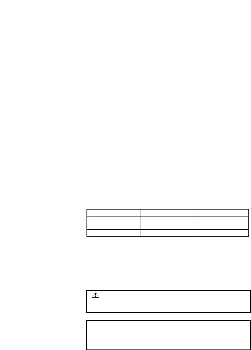
- Positioning plane
The positioning plane is determined by plane selection code G17, G18,
or G19.
The positioning axis is an axis other than the drilling axis.
- Drilling axis
Although canned cycles include tapping and boring cycles as well as
drilling cycles, in this chapter, only the term drilling will be used to
refer to operations implemented with canned cycles.
The drilling axis is a basic axis (X, Y, or Z) not used to define the
positioning plane, or any axis parallel to that basic axis.
The axis (basic axis or parallel axis) used as the drilling axis is
determined according to the axis address for the drilling axis specified
in the same block as G codes G73 to G89.
If no axis address is specified for the drilling axis, the basic axis is
assumed to be the drilling axis.
G code Positioning plane Drilling axis
G17 Xp-Yp plane Zp
G18 Zp-Xp plane Yp
G19 Yp-Zp plane Xp
Xp : X axis or an axis parallel to the X axis
Yp : Y axis or an axis parallel to the Y axis
Zp : Z axis or an axis parallel to the Z axis
G17 to G19 may be specified in a block in which any of G73 to G89 is
not specified.
CAUTION
Switch the drilling axis after canceling a canned
cycle.
NOTE
A parameter FXY (No. 6200 #0) can be set to the Z
axis always used as the drilling axis. When FXY=0,
the Z axis is always the drilling axis.
Contents Summary of Series 15i/150i - Model B Descriptions
- Page 1DESCRIPTIONS B-63782EN/01
- Page 2• No part of this manual may be reproduced in any form. • All specifications and designs are subject to change without notice. The export of this product is subject to the authorization of the government of the country from where the product is exported. In this manual we have tried as much as possi
- Page 3B-63782EN/01 DEFINITION OF WARNING, CAUTION, AND NOTE DEFINITION OF WARNING, CAUTION, AND NOTE This manual includes safety precautions for protecting the user and preventing damage to the machine. Precautions are classified into Warning and Caution according to their bearing on safety. Also, supplem
- Page 4
- Page 5B-63782EN/01 TABLE OF CONTENTS TABLE OF CONTENTS DEFINITION OF WARNING, CAUTION, AND NOTE ................................ s-1 I. GENERAL 1 GENERAL ..............................................................................................3 2 LIST OF SPECIFICATIONS ...............................
- Page 6TABLE OF CONTENTS B-63782EN/01 3.17 NURBS INTERPOLATION(G06.2) ..............................................................61 3.17.1 NURBS Interpolation Additional Functions ......................................................... 63 3.18 3-DIMENSIONAL CIRCULAR INTERPOLATION (G02.4 AND G03.4) ...
- Page 7B-63782EN/01 TABLE OF CONTENTS 5.7 DWELL MODE (G04) ..................................................................................84 5.8 AUTOMATIC FEEDRATE CONTROL BY AREA.........................................85 6 REFERENCE POSITION.............................................................
- Page 8TABLE OF CONTENTS B-63782EN/01 9.3 SPINDLE SPEED ANALOG OUTPUT.......................................................118 9.4 SPINDLE SPEED SERIAL OUTPUT.........................................................118 9.5 CONSTANT SURFACE SPEED CONTROL (G96, G97) ..........................119 9.6 SPINDLE
- Page 9B-63782EN/01 TABLE OF CONTENTS 13 FUNCTIONS TO SIMPLIFY PROGRAMMING...................................146 13.1 CANNED CYCLE.......................................................................................147 13.2 RIGID TAPPING ...................................................................
- Page 10TABLE OF CONTENTS B-63782EN/01 15.4 128 STRAIGHTNESS COMPENSATION POINTS....................................208 15.5 BACKLASH COMPENSATION..................................................................209 15.6 INTERPOLATED PITCH ERROR COMPENSATION................................210 15.7 CYCLIC SE
- Page 11B-63782EN/01 TABLE OF CONTENTS 18.4 C Executor .................................................................................................253 19 FUNCTIONS FOR HIGH-SPEED CUTTING ......................................255 19.1 DECELERATION BASED ON ACCELERATION DURING CIRCULAR INTERPOLATION ....
- Page 12TABLE OF CONTENTS B-63782EN/01 20.18 VERTICAL AXIS DROP PREVENTION FUNCTION .................................282 20.19 CUTTING/RAPID TRAVERSE IN-POSITION CHECK ..............................282 20.20 DECELERATION STOP UPON A POWER FAILURE...............................282 20.21 HIGH SPEED HRV MODE .
- Page 13B-63782EN/01 TABLE OF CONTENTS 22.3.1 Cycle Start ........................................................................................................... 298 22.4 EXECUTION OF AUTOMATIC OPERATION............................................299 22.4.1 Buffering.....................................
- Page 14TABLE OF CONTENTS B-63782EN/01 25 DISPLAY AND SETTING ...................................................................321 25.1 DISPLAY....................................................................................................322 25.2 LANGUAGE SELECTION....................................
- Page 15B-63782EN/01 TABLE OF CONTENTS 25.20 SUBSCREENS ..........................................................................................354 25.21 DIRECTORY DISPLAY / PUNCH FOR EACH GROUP ............................356 25.22 PROGRAM NAME 48 CHARACTERS ..............................................
- Page 16TABLE OF CONTENTS B-63782EN/01 28 DATA INPUT/OUTPUT.......................................................................380 28.1 READER/PUNCHER INTERFACES..........................................................381 28.1.1 Connection Port ...........................................................
- Page 17B-63782EN/01 TABLE OF CONTENTS 30.12 AXIS MOVE DIRECTION SIGNAL ............................................................394 30.13 RAPID TRAVERSING SIGNAL .................................................................394 30.14 TAPPING SIGNAL ....................................................
- Page 18
- Page 19I. GENERA
- Page 20
- Page 21B-63782EN/01 GENERAL 1.GENERAL 1 GENERAL The FANUC Series 15i CNC provides the highest level of performance for very-high-speed and very-high-precision machining. It can control 24 axes simultaneously. With functions such as precise trace control, called nano-interpolation, and fine HPCC for applyin
- Page 221.GENERAL GENERAL B-63782EN/01 Related manuals The following table lists the manuals related to the FANUC Series 15i, 150i. This manual is indicated by an asterisk(*). Table 1 (a) Manuals Related to the Series 15i, 150i Manual name Specification number DESCRIPTIONS B-63782EN * CONNECTION-MBNUAL (Har
- Page 23B-63782EN/01 GENERAL 2.LIST OF SPECIFICATIONS 2 LIST OF SPECIFICATIONS AA: Standard BB : Standard option CC : Option DD : Function included in another option NOTE) The use of some combinations of options is restricted. Series 15i Item Specifications Series 150i MB Axis control Controlled axes 3 axes
- Page 242.LIST OF SPECIFICATIONS GENERAL B-63782EN/01 Series 15i Item Specifications Series 150i MB Emergency stop AA Overtravel AA Stored stroke check 1 AA Stored stroke check 2 CC External stroke limit setting CC Stroke limit check before travel CC Mirror image Each axis AA Follow-up At emergency stop and
- Page 25B-63782EN/01 GENERAL 2.LIST OF SPECIFICATIONS Series 15i Item Specifications Series 150i MB Program restart CC Block restart CC Tool retract & recover CC Active block cancel CC Buffer register AA Multi buffer (5 blocks) AA Multi buffer (15 blocks) CC Multi buffer (100 blocks) CC Dry run AA Single bl
- Page 262.LIST OF SPECIFICATIONS GENERAL B-63782EN/01 Series 15i Item Specifications Series 150i MB Threading/Feed per revolution Equal lead thread cutting, inch thread cutting, CC continuous thread cutting Arbitrary spindle gear ratio thread cutting Included in “Thread cutting, per revolution feed”. DD Pol
- Page 27B-63782EN/01 GENERAL 2.LIST OF SPECIFICATIONS Series 15i Item Specifications Series 150i MB Automatic feedrate control by area CC Look-ahead acceleration/deceleration before AA interpolation Cutting point feedrate control Included in “Automatic corner override”. DD Advanced preview control AA Look-a
- Page 282.LIST OF SPECIFICATIONS GENERAL B-63782EN/01 Series 15i Item Specifications Series 150i MB Main program/sub program Sub program : 10 folds nested AA External device subprogram call function AA Custom macro Common variable : 600 CC Addition to custom macro common variables : CC total 900 Interrupt-t
- Page 29B-63782EN/01 GENERAL 2.LIST OF SPECIFICATIONS Series 15i Item Specifications Series 150i MB Tool offset memory C Separate memory for geometry and wear CC Separate memory for length compensation and cutter compensation Tool length compensation AA Tool offset CC Cutter compensation Same as “Cutter com
- Page 302.LIST OF SPECIFICATIONS GENERAL B-63782EN/01 Series 15i Item Specifications Series 150i MB Automatic exact stop check CC Skip for EGB axis CC Editing Part program storage length 80m (32Kbytes) AA Part program storage length 160m (64Kbytes) CC Part program storage length 320m CC (128Kbytes) Part pro
- Page 31B-63782EN/01 GENERAL 2.LIST OF SPECIFICATIONS Series 15i Item Specifications Series 150i MB Fine torque sensing Display unit with Graphic display function is needed. CC Hardware/software system configuration AA display NC format guidance Included in “Help function” AA Sub screen Display unit with Gr
- Page 322.LIST OF SPECIFICATIONS GENERAL B-63782EN/01 Series 15i Item Specifications Series 150i MB Others Status output signal NC ready, servo ready, rewinding, NC alarm, AA distribution completion, automatic operation, automatic operation start, automatic operation halt, reset, in-position, rapid traverse
- Page 33B-63782EN/01 GENERAL 2.LIST OF SPECIFICATIONS Software of personal computer part in case of the CNC system which is 150i or connected with personal computer via HSSB(High Speed Serial Bus) Items Specifications Remarks ® Operating system Windows 2000 *1 Extended library FOCAS1 *4 Software packages CN
- Page 342.LIST OF SPECIFICATIONS GENERAL B-63782EN/01 Hardware of CNC Display Unit with Personal Computer Function used in 150i Items Specifications Remarks ® CPU Pentium III, *1 TM Celeron , ® MMX Pentium Main memory Max. 128MBytes Hard disk 10GBytes Monitor 10.4" color TFT LCD (640×480 dots), Display Max.
- Page 35II NC FUNCTION
- Page 36
- Page 37B-63782EN/01 NC FUNCTIONS PREFACE PREFACE This part describes the functions that can be performed on all models. For the functions available with each model, see the list of specifications in Part I. - 19 -
- Page 381.CONROLLED AXES NC FUNCTIONS B-63782EN/01 1 CONROLLED AXES - 20 -
- Page 39B-63782EN/01 NC FUNCTIONS 1.CONROLLED AXES 1.1 CONTROLLED AXES Item Standard type Multiple axes type No. of basic controlled 3 axes (2 axes) axes Controlled axes Max. 10 axes (Cs axis is 2 Max. 24 axes expansion (total) axes) Basic simultaneously 2 axes controlled axes Simultaneously Up to Max. cont
- Page 401.CONROLLED AXES NC FUNCTIONS B-63782EN/01 1.2 AXIS NAME Names of axes can be optionally selected from X, Y, Z, A, B, C, U, V, and W. They can be set by parameter. Explanation - Axis name expansion function With the optional axis name expansion function, I, J, K, and E can also be used as axis names
- Page 41B-63782EN/01 NC FUNCTIONS 1.CONROLLED AXES 1.3 INCREMENT SYSTEM The increment system uses least input increment (for input) and least command increment (for output). The least input increment is the least increment for programming the travel distance. The least command increment is the least increme
- Page 421.CONROLLED AXES NC FUNCTIONS B-63782EN/01 By setting bit 0 (IM0) of parameter No. 1013 for ten-fold input unit, each increment system is set as shown in Table1.3 (b). Table1.3 (b) Name of Least input Least command increment Maximum stroke increment increment system 0.01 mm 0.001 mm 99999.999 mm IS-
- Page 43B-63782EN/01 NC FUNCTIONS 1.CONROLLED AXES 1.4 MAXIMUM STROKE Maximum stroke = Least command increment times 99999999 (For IS-D and IS-E, 999999999) See 1.3 Increment System. NOTE 1 A command exceeding the maximum stroke cannot be specified. 2 The actual stroke depends on the machine tool. - 25 -
- Page 442.PREPARATORY FUNCTION (G FUNCTION)NC FUNCTIONS B-63782EN/01 2 PREPARATORY FUNCTION (G FUNCTION) G codes on the Table2 is prepared. - 26 -
- Page 45B-63782EN/01 NC FUNCTIONS2.PREPARATORY FUNCTION (G FUNCTION) Table2 G code list Code Group Function G00 Positioning G01 Linear interpolation G02 Circular interpolation/Helical interpolation CW G03 Circular interpolation/Helical interpolation CCW G02.2 Involute interpolation CW G03.2 Involute interpo
- Page 462.PREPARATORY FUNCTION (G FUNCTION)NC FUNCTIONS B-63782EN/01 Table2 G code list Code Group Function G33 01 Threading G37 Automatic tool length measurement G38 00 Cutter compensation C vector retention G39 Cutter compensation C corner rounding G40 Cutter compensation cancel / Three dimensional compen
- Page 47B-63782EN/01 NC FUNCTIONS2.PREPARATORY FUNCTION (G FUNCTION) Table2 G code list Code Group Function G73 Peck drilling cycle G74 Counter tapping cycle G76 Fine boring cycle Canned cycle cancel / external operation function cancel / Electronic gear box G80 09 synchronous cancel (Command for hobbing ma
- Page 483.INTERPOLATION FUNCTION NC FUNCTIONS B-63782EN/01 3 INTERPOLATION FUNCTION - 30 -
- Page 49B-63782EN/01 NC FUNCTIONS 3.INTERPOLATION FUNCTION 3.1 POSITIONING (G00) Explanation The G00 command moves a tool to the position in the workpiece system specified with an absolute or an incremental command at a rapid traverse rate. In the absolute command, coordinate value of the end point is progr
- Page 503.INTERPOLATION FUNCTION NC FUNCTIONS B-63782EN/01 3.2 SINGLE DIRECTION POSITIONING (G60) Explanation It is always controlled to perform positioning to the end point from a single direction, for better precision in positioning. If direction from start point to end point is different from the predeci
- Page 51B-63782EN/01 NC FUNCTIONS 3.INTERPOLATION FUNCTION 3.3 LINEAR INTERPOLATION (G01) A tools move along a line to the specified position at the feedrate specified in F. The feedrate specified in F is effective until a new value is specified. It need not be specified for each block. Example X axis Progr
- Page 523.INTERPOLATION FUNCTION NC FUNCTIONS B-63782EN/01 3.4 CIRCULAR INTERPOLATION (G02,G03) Circular interpolation of optional angle from 0 deg to 360 deg can be specified. G02: Clockwise (CW) circular interpolation G03: Counterclockwise (CCW) circular interpolation Yp Xp Zp G03 G03 G03 G02 G02 G02 Xp Z
- Page 53B-63782EN/01 NC FUNCTIONS 3.INTERPOLATION FUNCTION Format Arc in the XpYp plane G02 I_J_ G17 Xp_Yp_ F_ ; G03 R_ Arc in the ZpXp plane G02 K_I_ G18 Zp_Xp_ F_ ; G03 R_ Arc in the YpZp plane G02 J_K_ G19 Yp_Zp_ F_ ; G03 R_ End point (x,y) End point (z,x) End point (y,z) Y X Z X Z Y i Start point k Star
- Page 543.INTERPOLATION FUNCTION NC FUNCTIONS B-63782EN/01 3.5 HELICAL INTERPOLATION (G02,G03) Helical interpolation which moved helically is enabled by specifying up to two other axes which move synchronously with the circular interpolation by circular commands. The basic command method involves simply add
- Page 55B-63782EN/01 NC FUNCTIONS 3.INTERPOLATION FUNCTION Z Tool path X Y The speed command specifies the feed rate along the tool path. Fig. 3.5 (b) Feedrate When Parameter HTG = 1 Format Synchronously with arc of XpYp plane G02 I_ J_ G17 Xp_Yp_ α_ (β _))F_ ; G03 R Synchronously with arc of ZpXp plane G02
- Page 563.INTERPOLATION FUNCTION NC FUNCTIONS B-63782EN/01 3.6 HELICAL INTERPOLATION B (G02,G03) Helical interpolation B allows the tool to move in helically. This can be done by specifying the circular interpolation command together with up to four axes. The command format for helical interpolation B consi
- Page 57B-63782EN/01 NC FUNCTIONS 3.INTERPOLATION FUNCTION 3.7 POLAR COORDINATE INTERPOLATION (G12.1,G13.1) Polar coordinate interpolation is a function that exercises contour control in converting a command programmed in a Cartesian coordinate system to the movement of a linear axis (movement of a tool) an
- Page 583.INTERPOLATION FUNCTION NC FUNCTIONS B-63782EN/01 Example Example of Polar Coordinate Interpolation Program Based on X Axis(Linear Axis) and C Axis (Rotary Axis) C'(hypothetical axis) C axis Path after cutter compensation Program path N204 N203 N205 N200 N202 N201 X-axis Tool N208 N206 N207 Z axis
- Page 59B-63782EN/01 NC FUNCTIONS 3.INTERPOLATION FUNCTION 3.7.1 Virtual Axis Direction Compensation for Polar Coordinate Interpolation In polar coordinate interpolation, this function compensates a machine if it has an error on the virtual axis, that is, the center of the rotation axis is not on the X-axis
- Page 603.INTERPOLATION FUNCTION NC FUNCTIONS B-63782EN/01 3.8 CYLINDRICAL INTERPOLATION (G07.1) The amount of travel of a rotary axis specified by an angle is once internally converted to a distance of a linear axis along the outer surface so that linear interpolation or circular interpolation can be perfo
- Page 61B-63782EN/01 NC FUNCTIONS 3.INTERPOLATION FUNCTION Example Example of a Cylindrical Interpolation Program O0001 (CYLINDRICAL INTERPOLATION); ‚C N01 G00 G90 Z100.0 C0 ; N02 G01 G91 G18 Z0 C0 ; N03 G07.1 C57299 ; N04 G90 G01 G42 Z120.0 D01 F250 ; Z ‚R N05 C30.0 ; N06 G02 Z90.0 C60.0 R30.0 ; N07 G01 Z7
- Page 623.INTERPOLATION FUNCTION NC FUNCTIONS B-63782EN/01 3.9 CYLINDRICAL INTERPOLATION CUTTING POINT CONTROL (G07.1) The conventional cylindrical interpolation function controls the tool center so that the tool axis always moves along a specified path on the cylindrical surface, towards the rotation axis
- Page 63B-63782EN/01 NC FUNCTIONS 3.INTERPOLATION FUNCTION Example - Example of cylindrical interpolation cutting point compensation The sample program below indicates the positional relationships between a workpiece and tool. O0001(CYLINDRICAL INTERPOLATION1) ; N01 G00 G90 Z100.0 C0 ; N02 G01 G91 G19 Z0 C0
- Page 643.INTERPOLATION FUNCTION NC FUNCTIONS B-63782EN/01 Positional relationship between the Positional relationship between the workpiece and tool of (1) workpiece and tool of (2) Rotation Workpiece Rotation 0° 0° 20° Cutting surface Tool Y-axis Y-axis Tool center Positional relationship between the Posi
- Page 65B-63782EN/01 NC FUNCTIONS 3.INTERPOLATION FUNCTION - Example of specifying cylindrical interpolation cutting point compensation and normal direction control at the same time Cutter compensation value No. 01 = 30 mm O0002(CYLINDRICAL INTERPOLATION2) ; N01 G00 G90 X100.0 A0 ; N02 G01 G91 G17 X0 A0 ; N
- Page 663.INTERPOLATION FUNCTION NC FUNCTIONS B-63782EN/01 3.10 INVOLUTE INTERPOLATION (G02.2,G03.2) Involute curve machining can be performed by using involute interpolation. Involute interpolation ensures continuous pulse distribution even in high-speed operation in small blocks, thus enabling smooth and
- Page 67B-63782EN/01 NC FUNCTIONS 3.INTERPOLATION FUNCTION Format Involute interpolation on the Xp-Yp plane G17 G02.2 Xp_ Yp_ I_ J_ R_ F_ ; G17 G03.2 Xp_ Yp_ I_ J_ R_ F_ ; Involute interpolation on the Zp-Xp plane G18 G02.2 Zp_ Xp_ K_ I_ R_ F_ ; G18 G03.2 Zp_ Xp_ K_ I_ R_ F_ ; Involute interpolation on the
- Page 683.INTERPOLATION FUNCTION NC FUNCTIONS B-63782EN/01 3.11 HELICAL INVOLUTE INTERPOLATION (G02.2,G03.3) This interpolation function applies involute Interpolation to two axes and directs movement for up to four other axes at the same time. This function is similar to the helical function used in circul
- Page 69B-63782EN/01 NC FUNCTIONS 3.INTERPOLATION FUNCTION 3.11.1 Involute Interpolation with a Linear Axis and Rotation Axis (G02.2,G03.3) In the polar coordinate interpolation mode, an involute curve can be machined using involute interpolation. The involute curve to be machined is drawn in the plane of t
- Page 703.INTERPOLATION FUNCTION NC FUNCTIONS B-63782EN/01 Example C (hypothetical axis) Path after tool compensation Program path N204 C-axis N205 Tool X-axis N201 N200 N202 Z-axis N203 Fig.3.11.1 (a) Involute interpolation during polar coordinate interpolation O0001 ; : N010 T0101 ; : N100 G90 G00 X15.0 C
- Page 71B-63782EN/01 NC FUNCTIONS 3.INTERPOLATION FUNCTION 3.12 EXPONENTIAL INTERPOLATION (G02.3,G03.3) Exponential interpolation exponentially changes the rotation of a workpiece with respect to movement on the rotary axis. Furthermore, exponential interpolation performs linear interpolation with respect t
- Page 723.INTERPOLATION FUNCTION NC FUNCTIONS B-63782EN/01 Format Positive rotation (ϖϖ=0) G02.3 X_ Y_ Z_ I_ J_ K_ R_ F_ Q_ ; Negative rotation (ϖ ϖ=1) G03.3 X_ Y_ Z_ I_ J_ K_ R_ F_ Q_ ; X_ : Specifies an end point with an absolute or incremental value. Y_ : Specifies an end point with an absolute or increm
- Page 73B-63782EN/01 NC FUNCTIONS 3.INTERPOLATION FUNCTION 3.13 SPLINE INTERPOLATION (G06.1) Spline interpolation produces a spline curve connecting specified points. When this function is used, the tool moves along the smooth curve connecting the points. The spline interpolation command eliminates the need
- Page 743.INTERPOLATION FUNCTION NC FUNCTIONS B-63782EN/01 3.14 SMOOTH INTERPOLATION To machine a part having sculptured surfaces, such as metal moldings used in automobiles and airplanes, a part program usually approximates the sculptured surfaces with minute line segments. As shown in the following figure
- Page 75B-63782EN/01 NC FUNCTIONS 3.INTERPOLATION FUNCTION 3.15 HYPOTHETICAL AXIS INTERPOLATION (G07) In helical interpolation, when pulses are distributed with one of the circular interpolation axes set to a hypothetical axis, sine interpolation is enabled. When one of the circular interpolation axes is se
- Page 763.INTERPOLATION FUNCTION NC FUNCTIONS B-63782EN/01 3.16 SPIRAL INTERPOLATION, CONICAL INTERPOLATION (G02,G03) Spiral interpolation is enabled by specifying the circular interpolation command together with a desired number of revolutions or a desired increment (decrement) for the radius per revolutio
- Page 77B-63782EN/01 NC FUNCTIONS 3.INTERPOLATION FUNCTION Format - Spiral interpolation Xp-Yp plane G02 G17 X_Y_I_J_Q_L_F_ ; G03 Zp-Yp plane G02 G18 Z_X_K_I_Q_L_F_ ; G03 Yp-Zp plane G02 G19 Y_Z_J_K_Q_L_F_ ; G03 X,Y,Z :Coordinates of the end point L : Number of revolutions (positive value without a decimal
- Page 783.INTERPOLATION FUNCTION NC FUNCTIONS B-63782EN/01 - Conical interpolation Xp-Yp plane G17 G02/G03 X_Y_I_J_Z_Q_L_F_ ; Zp-Yp plane G18 G02/G03 Z_X_K_I_Y_Q_L_F_ ; Yp-Zp plane G19 G02/G03 Y_Z_J_K_X_Q_L_F_ ; X,Y,Z : Coordinates of the end point L : Number of revolutions (positive value without a decimal
- Page 79B-63782EN/01 NC FUNCTIONS 3.INTERPOLATION FUNCTION 3.17 NURBS INTERPOLATION(G06.2) Many computer-aided design (CAD) systems used to design metal dies for automobiles utilize non-uniform rational B-spline (NURBS) to express a sculptured surface or curve for the metal dies. This function enables NURBS
- Page 803.INTERPOLATION FUNCTION NC FUNCTIONS B-63782EN/01 Format G06.2 [P_ ] K_ IP_ [R_ ] [F_ ] ; K_ IP_ [R_ ] ; K_ IP_ [R_ ] ; K_ IP_ [R_ ] ; … K_ IP_ [R_ ] ; K_ ; … K_ ; G01… … G06.2 : Start NURBS interpolation mode P_ : Rank of NURBS curve IP_ : Control point (Up to the maximum number of controlled axes
- Page 81B-63782EN/01 NC FUNCTIONS 3.INTERPOLATION FUNCTION 3.17.1 NURBS Interpolation Additional Functions The functions below are added to the NURBS interpolation function of the FANUC Series 15i. - Parametric feedrate control The maximum feedrate of each segment is determined by a specified feedrate and a
- Page 823.INTERPOLATION FUNCTION NC FUNCTIONS B-63782EN/01 F(1) 1 segment F F(t) F F(0) F Fig. 3.17.1(a) - Rollover If a control point is specified in the absolute mode (G90) for a rotation axis subject to rollover, the relative position shift of the control point based on a shortcut is calculated after rol
- Page 83B-63782EN/01 NC FUNCTIONS 3.INTERPOLATION FUNCTION 3.18 3-DIMENSIONAL CIRCULAR INTERPOLATION (G02.4 AND G03.4) Specifying an intermediate and end point on an arc enables circular interpolation in a 3-dimensional space. Format The command format is as follows: G02.4 XX1 YY1 ZZ1 αα1 β β1 ; First block
- Page 844.THREAD CUTTING NC FUNCTIONS B-63782EN/01 4 THREAD CUTTING - 66 -
- Page 85B-63782EN/01 NC FUNCTIONS 4.THREAD CUTTING 4.1 THREAD CUTTING (G33) The G33 command produces a straight or tapered thread having a constant lead. L L : Lead L L Straight thread Taper thread Front thread (Stroke thread) Fig.4.1 (a) Thread Format G33 IP_ F_ Q_ ; F_ : Larger component of lead Q_ : Angl
- Page 864.THREAD CUTTING NC FUNCTIONS B-63782EN/01 When a tapered thread is produced, the lead must be specified with the magnitude of a larger component. A lathe which holds and rotates a workpiece can produce a tapered thread on the workpiece. X Lead of tapered thread LX α Z LZ When angle α is less than o
- Page 87B-63782EN/01 NC FUNCTIONS 4.THREAD CUTTING 4.2 INCH THREADING (G33) When a number of thread ridges per inch is specified with address E, an inch thread can be produced with high precision. Format G33 IP_ E_ Q_; E_ : Number of thread ridges per inch Q_ : Number of thread ridges per inch at threading
- Page 884.THREAD CUTTING NC FUNCTIONS B-63782EN/01 4.3 CONTINUOUS THREADING (G33) Continuous threading can be executed when multiple blocks containing the threading command are specified in succession. Explanation At the interface between blocks, the system keeps synchronous control of the spindle as much a
- Page 89B-63782EN/01 NC FUNCTIONS 5.FEED FUNCTION 5 FEED FUNCTION - 71 -
- Page 905.FEED FUNCTION NC FUNCTIONS B-63782EN/01 5.1 RAPID TRAVERSE Positioning of each axis is done in rapid motion by the positioning command (G00). There is no need to program rapid traverse rate, because the rates are set in the parameter (per axis) Least command increment Rapid traverse rate range 0.0
- Page 91B-63782EN/01 NC FUNCTIONS 5.FEED FUNCTION 5.2 CUTTING FEED After an F code, specify the feedrate value for linear interpolation (G01), circular interpolation (G02 and G03), or the like. 5.2.1 Tangential Speed Constant Control Cutting feed is controlled so that the tangential feedrate is always set a
- Page 925.FEED FUNCTION NC FUNCTIONS B-63782EN/01 5.2.4 Feed Per Revolution (G95) With the per revolution feed mode G95, tool feed rate per revolution of the spindle is directly commanded by numeral after F. A position coder must be mounted on the spindle. However, the feed-per-revolution command can be ena
- Page 93B-63782EN/01 NC FUNCTIONS 5.FEED FUNCTION 5.2.7 Setting Input of Cutting Feedrate With some machines, the cutting feedrate need not be changed frequently during machining. For such machines, a cutting feedrate (a non-zero value) can be set in parameter. With this function, the cutting feedrate (F co
- Page 945.FEED FUNCTION NC FUNCTIONS B-63782EN/01 5.3 OVERRIDE 5.3.1 Feedrate Override The per minute feed (G94) and per rotation feed (G95) can be overrided by: 0 to 254% (per every 1%). In inverse time, feed rate converted to per minute feed is overridden. Feed rate override cannot be performed to F1-digi
- Page 95B-63782EN/01 NC FUNCTIONS 5.FEED FUNCTION 5.4 ACCELERATION/DECELERATION CONTROL 5.4.1 Automatic Acceleration/Deceleration Control After Interpolation Acceleration and deceleration is performed when starting and ending movement, resulting in smooth start and stop. Automatic acceleration/deceleration
- Page 965.FEED FUNCTION NC FUNCTIONS B-63782EN/01 Linear acceleration/deceleration F : Command speed Speed T : Acceleration/ F deceleration time constant 0 Time T T Bell-shaped acceleration/deceleration F : Command speed Speed T : Acceleration/ deceleration time F constant 0 Time T T Exponential function ac
- Page 97B-63782EN/01 NC FUNCTIONS 5.FEED FUNCTION 5.4.2 Acceleration/Deceleration before Interpolation of Linear-Type Rapid Traverse Conventionally, only acceleration/deceleration after interpolation could be applied to rapid traverse. This function enables acceleration/deceleration before interpolation to
- Page 985.FEED FUNCTION NC FUNCTIONS B-63782EN/01 5.4.3 Optimum Torque Acceleration/Deceleration This function enables acceleration/deceleration in accordance with the torque characteristics of the motor and the characteristics of the machines due to its friction and gravity. Usually, because of the frictio
- Page 99B-63782EN/01 NC FUNCTIONS 5.FEED FUNCTION 5.5 PMC AXIS CONTROL CONSTANT FEEDRATE COMMAND ACCELERATION/DECELERATION FUNCTION When a constant feedrate is specified with the PMC axis control function, linear acceleration/deceleration can be applied to the specified feedrate at the start and end of move
- Page 1005.FEED FUNCTION NC FUNCTIONS B-63782EN/01 5.6 SPEED CNTROL COMMAND AT THE CORNER OF BLOCK 5.6.1 Exact Stop (G09) Move command in blocks commanded with G09 decelerates at the end point, and in-position check is performed. G09 command is not necessary for deceleration at the end point for positioning
- Page 101B-63782EN/01 NC FUNCTIONS 5.FEED FUNCTION 5.6.5 Automatic Corner Override (G62) When G62 is commanded during cutter compensation, cutting feed rate is automatically overridden at corner. The cutting quantity per unit time of the corner is thus controlled not to increase. This G62 is valid till G61 (
- Page 1025.FEED FUNCTION NC FUNCTIONS B-63782EN/01 5.7 DWELL MODE (G04) By specifying a dwell, the execution of the next block is delayed by the specified time. Bit 5 (DWL) of parameter No. 2400 can specify dwell for each rotation in feed per rotation mode (G95). Format Per second dwell G04 X_ (or P_) ; P_ o
- Page 103B-63782EN/01 NC FUNCTIONS 5.FEED FUNCTION 5.8 AUTOMATIC FEEDRATE CONTROL BY AREA When an area on the XY plane(*1) is specified in cutting mode in automatic operation, area override can be applied to a specified feedrate(*2) if the tool is in the specified area. Up to four areas can be set on the XY
- Page 1046.REFERENCE POSITION NC FUNCTIONS B-63782EN/01 6 REFERENCE POSITION - 86 -
- Page 105B-63782EN/01 NC FUNCTIONS 6.REFERENCE POSITION 6.1 MANUAL REFERENCE POSITION RETURN Positioning to a reference position can be performed by manual operation. The grid method of manual reference position return is supported: The tool starts moving at the rapid traverse rate when jog feed mode (JOG),
- Page 1066.REFERENCE POSITION NC FUNCTIONS B-63782EN/01 6.2 SETTING THE REFERENCE POSITION WITHOUT DOGS This function moves the machine to around the reference position set for each axis in the manual continuous feed mode. Then it sets the reference position for the machine in the manual reference position r
- Page 107B-63782EN/01 NC FUNCTIONS 6.REFERENCE POSITION 6.3 AUTOMATIC REFERENCE POSITION RETURN (G28, G29) - Return to reference position (G28) With the G28 command, the commanded axis is positioned to the reference position via the commanded point. After positioning, the reference position return end lamp l
- Page 1086.REFERENCE POSITION NC FUNCTIONS B-63782EN/01 6.4 REFERENCE POSITION RETURN CHECK (G27) This function is used to check whether the reference position return command was performed correctly. When G27 is commanded, the commanded axis is positioned to the specified position, reference position return
- Page 109B-63782EN/01 NC FUNCTIONS 6.REFERENCE POSITION 6.6 FLOATING REFERENCE POSITION RETURN (G30.1) It is possible to return the tool to the floating reference position by commanding the G30.1. The floating reference position is located on the machine and can be a reference position of some sort of machin
- Page 1106.REFERENCE POSITION NC FUNCTIONS B-63782EN/01 Example G30.1 G90 X50.0 Y40.0 ; Y Intermediate position (50,40) Floating reference position Workpiece X - 92 -
- Page 111B-63782EN/01 NC FUNCTIONS 6.REFERENCE POSITION 6.7 Reference Position Shift When reference position return is performed using a grid method, the reference position can be shifted by a parameter-set distance without having to move the deceleration dog. This function is enabled by setting bit 4 of par
- Page 1127.COORDINATE SYSTEM NC FUNCTIONS B-63782EN/01 7 COORDINATE SYSTEM By teaching the CNC the position the tool is to arrive, the CNC moves the tool to that position. The position is specified using coordinates on a certain coordinate system. There are three types of coordinate systems. - Machine coordi
- Page 113B-63782EN/01 NC FUNCTIONS 7.COORDINATE SYSTEM 7.1 MACHINE COORDINATE SYSTEM (G53) Machine coordinate system is a coordinate system set with a zero point proper to the machine system. A coordinate system in which the reference point becomes the parameter-preset coordinate value when manual reference
- Page 1147.COORDINATE SYSTEM NC FUNCTIONS B-63782EN/01 7.2 WORKPIECE COORDINATE SYSTEM A coordinate system used for machining a workpiece is referred to as a workpiece coordinate system. A workpiece coordinate system can be set using one of the two methods described below. (1) Method using G92 A workpiece co
- Page 115B-63782EN/01 NC FUNCTIONS 7.COORDINATE SYSTEM - Example 2 Set the reference point on the tool holder or turret as shown in the figure below, then specify G92 at the beginning of the program. By specifying an absolute command in this condition, the reference point is moved to a specified position. To
- Page 1167.COORDINATE SYSTEM NC FUNCTIONS B-63782EN/01 7.2.2 Setting Workpiece Coordinate System (G54 to G59) Six workpiece coordinate systems can be set. These six systems are decided by setting the distances of each axis from the machine zero point to the zero points of the coordinate systems. Workpiece ze
- Page 117B-63782EN/01 NC FUNCTIONS 7.COORDINATE SYSTEM 7.3 LOCAL COORDINATE SYSTEM With G52 commanded, the local coordinate system with the commanded position as zero point can be set. Once the local coordinate system is set, values specified in subsequent move commands are regarded as coordinate values on t
- Page 1187.COORDINATE SYSTEM NC FUNCTIONS B-63782EN/01 7.3.1 Workpiece Origin Offset Value Change G10 command is used to change workpiece origin offsets. When G10 is commanded in absolute command (G90), the commanded workpiece origin offsets becomes the new workpiece origin offsets, and when G10 is commanded
- Page 119B-63782EN/01 NC FUNCTIONS 7.COORDINATE SYSTEM 7.3.3 Workpiece Coordinate System Preset (G92.1) The workpiece coordinate system with its zero position away by the workpiece zero offset amount from the machine coordinate system zero position is set by returning the tool to the reference point by a man
- Page 1207.COORDINATE SYSTEM NC FUNCTIONS B-63782EN/01 7.3.4 Automatically Presetting the Workpiece Coordinate System This function automatically presets the workpiece coordinate system to the position where machine lock is applied, after the machine is operated with machine lock set on and machine lock is r
- Page 121B-63782EN/01 NC FUNCTIONS 7.COORDINATE SYSTEM 7.4 PLANE SELECTION Select the planes for circular interpolation, cutter compensation, and drilling by G-code. The following table lists G-codes and the planes selected by them. Explanation Table7.4 Plane selected by G code G code Selected plane Xp Yp Zp
- Page 1227.COORDINATE SYSTEM NC FUNCTIONS B-63782EN/01 7.5 PLANE CONVERSION FUNCTION This function converts a machining program created on the G17 plane in the right-hand Cartesian coordinate system to programs for other planes specified by G17.1Px commands, so that the same figure appears on each plane when
- Page 123B-63782EN/01 NC FUNCTIONS 7.COORDINATE SYSTEM (2) G17.1 P2 Z X Y G18 plane X indicates that the negative direction of the axis perpendicular to the page is the direction coming out the page (in this case, the Y-axis perpendicular to the XZ plane). (3) G17.1 P3 Z Y X G19 plane (4) G17.1 P4 Z X Y G18
- Page 1247.COORDINATE SYSTEM NC FUNCTIONS B-63782EN/01 (5) G17.1 P5 Z Y X G19 plane - 106 -
- Page 125B-63782EN/01 NC FUNCTIONS 7.COORDINATE SYSTEM 7.6 ROTARY TABLE DYNAMIC FIXTURE OFFSET The rotary table dynamic fixture offset function saves the operator the trouble of re-setting the workpiece coordinate system when the rotary table rotates before cutting is started. With this function the operator
- Page 1268.COORDINATE VALUE AND DIMENSION NC FUNCTIONS B-63782EN/01 8 COORDINATE VALUE AND DIMENSION - 108 -
- Page 127B-63782EN/01 NC FUNCTIONS 8.COORDINATE VALUE AND DIMENSION 8.1 ABSOLUTE AND INCREMENTAL PROGRAMMING There are two ways to command travels of the tool; the absolute command, and the incremental command. In the absolute command, coordinate value of the end position is programmed; in the incremental co
- Page 1288.COORDINATE VALUE AND DIMENSION NC FUNCTIONS B-63782EN/01 8.2 POLAR COORDINATE COMMAND (G15, G16) The end point coordinate value can be input in polar coordinates (radius and angle). Use G15, G16 for polar coordinates command. Format G16; Polar coordinate system command cancel G15; Polar coordinate
- Page 129B-63782EN/01 NC FUNCTIONS 8.COORDINATE VALUE AND DIMENSION N3 Y150.0 ; Specifying a distance of 100 mm and an angle of 150 degrees N4 Y270.0 ; Specifying a distance of 100 mm and an angle of 270 degrees N5 G15 G80 ; Canceling the polar coordinate command - 111 -
- Page 1308.COORDINATE VALUE AND DIMENSION NC FUNCTIONS B-63782EN/01 8.3 INCH/METRIC CONVERSION (G20,G21) Conversion of inch and metric input can be commanded by the G code command. Format G20 ; Inch input G21 ; mm input Whether the output is in inch system or metric system is parameter-set when the machine i
- Page 131B-63782EN/01 NC FUNCTIONS 8.COORDINATE VALUE AND DIMENSION 8.4 DECIMAL POINT INPUT/POCKET CALCULATOR TYPE DECIMAL POINT INPUT Numerals can be input with decimal points. Decimal points can be used basically in numerals with units of distance, speed, and angle. The position of the decimal point is at
- Page 1328.COORDINATE VALUE AND DIMENSION NC FUNCTIONS B-63782EN/01 8.5 DIAMETER AND RADIUS PROGRAMMING Since the section of a workpiece to be machined in a lathe is usually circular, the sectional dimensions can be programmed with diameters or radiuses in an NC unit. Specifying the dimensions of a workpiece
- Page 133B-63782EN/01 NC FUNCTIONS 8.COORDINATE VALUE AND DIMENSION 8.6 PROGRAMMABLE SWITCHING OF DIAMETER/RADIUS SPECIFICATION Assume that diameter or radius specification has been selected for each controlled axis by using bit 3 (DIA) of parameter No. 1006. This function allows the use of a G code to switc
- Page 1348.COORDINATE VALUE AND DIMENSION NC FUNCTIONS B-63782EN/01 8.7 LINEAR AXIS AND ROTATION AXIS A linear axis refers to an axis moving linearly, and for it values are specified in mm or inches. A rotation axis refers to a rotating axis, and for it values are specified in degrees. For rotation axes, not
- Page 135B-63782EN/01 NC FUNCTIONS 9.SPINDLE SPEED FUNCTION 9 SPINDLE SPEED FUNCTION - 117 -
- Page 1369.SPINDLE SPEED FUNCTION NC FUNCTIONS B-63782EN/01 9.1 S CODE OUTPUT Specify the spindle speed with up to ten digits immediately after address S. The 5-digit numeric value is output to the PMC as a 32-bit binary code. The code is maintained until another S is specified. The maximum number and sign (
- Page 137B-63782EN/01 NC FUNCTIONS 9.SPINDLE SPEED FUNCTION 9.5 CONSTANT SURFACE SPEED CONTROL (G96, G97) Specify the surface speed (relative speed between the tool and workpiece) following S. The spindle is rotated so that the surface speed is constant regardless of the position of the tool. Spindle speed N
- Page 1389.SPINDLE SPEED FUNCTION NC FUNCTIONS B-63782EN/01 9.6 SPINDLE SPEED CLAMP (G92) With the following command, a maximum spindle speed can be set: G92 S_; (where S_: Maximum spindle speed in min-1) A set maximum spindle speed is output to the PMC as a 16-bit binary code. On the PMC, the spindle speed
- Page 139B-63782EN/01 NC FUNCTIONS 9.SPINDLE SPEED FUNCTION 9.8 SPINDLE POSITIONING The spindle positioning function moves the spindle connected to the spindle motor by a given angle so that the workpiece attached to the spindle is positioned at a desired angle. With this function, any portion of the workpie
- Page 1409.SPINDLE SPEED FUNCTION NC FUNCTIONS B-63782EN/01 9.9 SPINDLE ORIENTATION You can perform spindle orientation simply by mounting a position coder on the spindle. Stoppers or pins for physically stopping the spindle at a specified position are not necessary. A spindle can be instantly oriented, even
- Page 141B-63782EN/01 NC FUNCTIONS 9.SPINDLE SPEED FUNCTION 9.11 SPINDLE SPEED FLUCTUATION DETECTION If the actual spindle speed becomes lower or higher than that specified because of the condition of the machine, an overheat alarm (SP0242) is issued, and spindle speed fluctuation detection alarm signal SPAL
- Page 1429.SPINDLE SPEED FUNCTION NC FUNCTIONS B-63782EN/01 G26 places the system in spindle speed fluctuation detection enabled mode and sets the P, Q, R, and I command addresses in parameters Nos. 5071, 5702, 5721, and 5722. The parameter numbers corresponding to the command addresses are as follows: Comma
- Page 143B-63782EN/01 NC FUNCTIONS 10.TOOL FUNCTION 10 TOOL FUNCTION - 125 -
- Page 14410.TOOL FUNCTION NC FUNCTIONS B-63782EN/01 10.1 TOOL SELECTION FUNCTION For tool selection, an address T followed by a numeric value of no more than 10 digits can be used to specify a tool number. When a T code is specified, the code signal corresponding to the tool number and strobe signal are outp
- Page 145B-63782EN/01 NC FUNCTIONS 10.TOOL FUNCTION 10.2 TOOL LIFE MANAGEMENT FUNCTION 10.2.1 Tool Life Management Function General Tools are grouped and the tool life (use count or use time) is predetermined for each group. Each time a tool belonging to a group is used, its life value is incremented. Once t
- Page 14610.TOOL FUNCTION NC FUNCTIONS B-63782EN/01 - Tool group number The Max. number of groups and the number of tools per group that can be registered are set by parameter (GS1,GS2 No. 7400#0, #1). The Max. number of The Max. number of The Max. number of groups and tools groups and tools groups and tools
- Page 147B-63782EN/01 NC FUNCTIONS 10.TOOL FUNCTION 10.2.2 Addition of Tool Pairs for Tool Life Management 512 Pairs The number of groups that can be registered in the tool life management function and the allowable number of tools per group can be selected from the following four combinations. One of the co
- Page 14811.MISCELLANEOUS FUNCTIONS NC FUNCTIONS B-63782EN/01 11 MISCELLANEOUS FUNCTIONS - 130 -
- Page 149B-63782EN/01 NC FUNCTIONS 11.MISCELLANEOUS FUNCTIONS 11.1 AUXILIARY FUNCTION When a numeral is specified following address M, code signal and a strobe signal are sent to the machine. The machine uses these signals to turn on or off its functions. Usually, only one M code can be specified in one bloc
- Page 15011.MISCELLANEOUS FUNCTIONS NC FUNCTIONS B-63782EN/01 11.2 MULTIPLE M COMMANDS IN A SINGLE BLOCK In general, only one M code can be specified in a block. However, up to five M codes can be specified at once in a block by setting bit 7 (M3B) of parameter No. 3404 to 1. Up to five M codes specified in
- Page 151B-63782EN/01 NC FUNCTIONS 11.MISCELLANEOUS FUNCTIONS 11.3 THE SECOND AUXILIARY FUNCTIONS When a numeric value is specified after address B, the code signal and strobe signal are output. This code is held until the next B code is output. A B code is used, for example, for rotation axis indexing on th
- Page 15211.MISCELLANEOUS FUNCTIONS NC FUNCTIONS B-63782EN/01 11.4 HIGH-SPEED M/S/T/B INTERFACE General To accelerate M/S/T/B function execution, the high-speed M/S/T/B interface has simplified the transfer of the strobe and completion signals of the M/S/T/B functions. Whether to use the usual system or high
- Page 153B-63782EN/01 NC FUNCTIONS 11.MISCELLANEOUS FUNCTIONS Next block Code signal Mxx Myy Strobe signal MF PMC side operation Completion signal FIN Fig. 11.4 (b) Timing chart of the usual system A high-speed interface can also be used for multiple M commands issued for one block. This interface provides s
- Page 15412.PROGRAM CONFIGURATION NC FUNCTIONS B-63782EN/01 12 PROGRAM CONFIGURATION - 136 -
- Page 155B-63782EN/01 NC FUNCTIONS 12.PROGRAM CONFIGURATION 12.1 PROGRAM NUMBER A program number is given to each program to distinguish a program from other programs. The program number is given at the head of each program, with a 8-digit number after the address O. Program number of the program currently u
- Page 15612.PROGRAM CONFIGURATION NC FUNCTIONS B-63782EN/01 12.4 SUB PROGRAM When there are fixed sequences or frequently repeated patterns in a program, programming can be simplified by entering these pattern as sub programs to the memory. Sub program is called by M98, and M99 commands return from the sub p
- Page 157B-63782EN/01 NC FUNCTIONS 12.PROGRAM CONFIGURATION - Return from subprogram M99 [P_ ] ; P_ : Return destination sequence number P_ is optional. If omitted, a return is made to the block next to that in which the call is made. M99 need not necessarily be within a single block. - 139 -
- Page 15812.PROGRAM CONFIGURATION NC FUNCTIONS B-63782EN/01 12.5 EXTERNAL DEVICE SUBPROGRAM CALL (M198) During memory operation, subprograms registered in an external device (such as Handy File, data server, and so forth) connected to the CNC can be called and executed. Format M198 P_ L_ ; P : program-number
- Page 159B-63782EN/01 NC FUNCTIONS 12.PROGRAM CONFIGURATION 12.6 SEQUENCE NUMBER Sequence number can be given in a 8-digit number after the address N at the head of the program block. The sequence number of the program under execution is always displayed on the screen. The sequence number can also be searche
- Page 16012.PROGRAM CONFIGURATION NC FUNCTIONS B-63782EN/01 12.8 BASIC ADDRESSES AND COMMAND VALUE RANGE The following table shows the basic addresses and the range of values to be specified. The range, however, is that of CNC. Note that the range of the machine is different from this. Function Address Input
- Page 161B-63782EN/01 NC FUNCTIONS 12.PROGRAM CONFIGURATION *3 When a millimeter machine is used with inch input, the maximum specifiable range of a dimension word is as follows: Increment system The maximum specifiable range IS-A ±39370.078inch IS-B ±39370.0787inch IS-C ±3937.00787inch IS-D ±393.700787inch
- Page 16212.PROGRAM CONFIGURATION NC FUNCTIONS B-63782EN/01 12.9 PROGRAM FORMAT The variable block word address format with decimal point is adopted as tape format. See List of Program Format in Appendix B for details on program formats. 12.10 LABEL SKIP Label skip function is valid in the following cases, a
- Page 163B-63782EN/01 NC FUNCTIONS 12.PROGRAM CONFIGURATION 12.12 OPTIONAL BLOCK SKIP When a slash and number ( /n) is programmed at the head of a program, and when the machine is operated with the optional block skip switch n on the machine operator's panel on, information in the block commanded with the /n
- Page 16413.FUNCTIONS TO SIMPLIFY PROGRAMMING NC FUNCTIONS B-63782EN/01 13 FUNCTIONS TO SIMPLIFY PROGRAMMING - 146 -
- Page 165B-63782EN/01 NC FUNCTIONS 13.FUNCTIONS TO SIMPLIFY PROGRAMMING 13.1 CANNED CYCLE Canned cycles make it easier for the programmer to create programs. With a canned cycle, a frequently-used machining operation can be specified in a single block with a G function; without canned cycles, normally more t
- Page 16613.FUNCTIONS TO SIMPLIFY PROGRAMMING NC FUNCTIONS B-63782EN/01 - Canned cycle I An independent output signal is used for each of reverse spindle rotation and spindle stop. When bit 0 (FXB) of parameter No. 6201 is set to 0, canned cycle I is set. - Canned cycle II M codes are used as output signals
- Page 167B-63782EN/01 NC FUNCTIONS 13.FUNCTIONS TO SIMPLIFY PROGRAMMING - Travel distance along the drilling axis G90/G91 The travel distance along the drilling axis varies for G90 and G91 as follows : G90 (Absolute Command) G91 (Incremental Command) R Point R R Point R Z=0 Z Point Z Point Z Z - Drilling mod
- Page 16813.FUNCTIONS TO SIMPLIFY PROGRAMMING NC FUNCTIONS B-63782EN/01 G98(Return to initial level ) G99(Return to point R level) Initial level Point R level - Repeat To repeat drilling for equally-spaced holes, specify the number of repeats in K_. K is effective only within the block where it is specified.
- Page 169B-63782EN/01 NC FUNCTIONS 13.FUNCTIONS TO SIMPLIFY PROGRAMMING Canned cycles Operation G code Function G98 mode G99 mode Initial level R point R point R point level G73 High-speed peck drilling cycle q q d d q q d d q q Z point Z point Initial level G74 Spindle CCW Counter tapping cycle Spindle CCW
- Page 17013.FUNCTIONS TO SIMPLIFY PROGRAMMING NC FUNCTIONS B-63782EN/01 Operation G code Function G98 mode G99 mode Initial level G81 Drilling cycle (Spot drilling) R point R point R point level Z point Z point Initial level G82 Drilling cycle (Counter boring) R point R point R point level Z point Z point P
- Page 171B-63782EN/01 NC FUNCTIONS 13.FUNCTIONS TO SIMPLIFY PROGRAMMING Operation G code Function G98 mode G99 mode Initial level G85 Boring cycle R point R point R point level Z point Z point Spindle CW Initial level G86 Spindle CW R point R point R point level Boring cycle Z point Z point Spindle CCW Spind
- Page 17213.FUNCTIONS TO SIMPLIFY PROGRAMMING NC FUNCTIONS B-63782EN/01 Operation G code Function G98 mode G99 mode Spindle CW Initial level Spindle CW G88 R point R point R point level Boring cycle Z point Z point P P Dwell Dwell Spindle stop Spindle stop Initial level G89 R point R point R point level Bori
- Page 173B-63782EN/01 NC FUNCTIONS 13.FUNCTIONS TO SIMPLIFY PROGRAMMING 13.2 RIGID TAPPING In tapping, an amount of travel per spindle revolution along the Z-axis must match the screw pitch of the tapper. This means that the optimum tapping must satisfy the following condition: P = F/S, where P : Tapper scre
- Page 17413.FUNCTIONS TO SIMPLIFY PROGRAMMING NC FUNCTIONS B-63782EN/01 G84.2 X_ Y_ Z_ R_ P_ F_ L_ S_ ; X_ Y_: Hole position data Z_ : The distance from point R to the bottom of the hole and the position of the bottom of the hole R_ : The distance from the initial level to point R level P_ : Dwell time at th
- Page 175B-63782EN/01 NC FUNCTIONS 13.FUNCTIONS TO SIMPLIFY PROGRAMMING A gear can be inserted between the spindle and its motor (n:m) and between the spindle and position coder (N:M), as shown below. Spindle control Error Spindle Spindle motor counter amplifier Gear ratio n:m Position Gear ratio N:M Spindle
- Page 17613.FUNCTIONS TO SIMPLIFY PROGRAMMING NC FUNCTIONS B-63782EN/01 13.3 EXTERNAL MOTION FUNCTION (G81) Upon completion of positioning in each block in the program, an external operation function signal can be output to allow the machine to perform specific operation. Concerning this operation, refer to
- Page 177B-63782EN/01 NC FUNCTIONS 13.FUNCTIONS TO SIMPLIFY PROGRAMMING 13.4 OPTIONAL ANGLE CHAMFERING AND CORNER ROUNDING Chamfering and corner rounding blocks can be inserted automatically between the following: - Between linear interpolation and linear interpolation blocks - Between linear interpolation a
- Page 17813.FUNCTIONS TO SIMPLIFY PROGRAMMING NC FUNCTIONS B-63782EN/01 13.5 PROGRAMMABLE MIRROR IMAGE (G50.1, G51.1) Mirror image can be commanded on each axis by programming. Ordinary mirror image (commanded by remote switch or setting) comes after the programmable mirror image is applied. - Setting of pro
- Page 179B-63782EN/01 NC FUNCTIONS 13.FUNCTIONS TO SIMPLIFY PROGRAMMING Y Axis of symmetry (X=50) (2) (1) 100 60 50 Axis of symmetry (Y=50) 40 0 (3) (4) 0 40 50 60 100 X (1) Original image of a programmed command (2) Image symmetrical about a line parallel to the Y-axis and crossing the X-axis at 50 (3) Imag
- Page 18013.FUNCTIONS TO SIMPLIFY PROGRAMMING NC FUNCTIONS B-63782EN/01 13.6 INDEX TABLE INDEXING FUNCTION By specifying indexing positions (angles) for the indexing axis (one arbitrary axis), the index table of the machining center can be indexed. To command for indexing, an indexing angle is only to be spe
- Page 181B-63782EN/01 NC FUNCTIONS 13.FUNCTIONS TO SIMPLIFY PROGRAMMING 13.7 FIGURE COPY (G72.1,G72.2) Machining can be repeated after moving or rotating the figure using a subprogram. - Specifying two or more commands to copy a figure G72.1 cannot be specified more than once in a subprogram for making a rot
- Page 18213.FUNCTIONS TO SIMPLIFY PROGRAMMING NC FUNCTIONS B-63782EN/01 13.7.1 Rotation Copy Machining can be repeated after rotating the figure using a subprogram. Xp-Yp plane (specified by G17) : G72.1 P_ L_ Xp_ Yp_ R_ ; Zp-Xp plane (specified by G18) : G72.1 P_ L_ Zp_ Xp_ R_ ; Yp-Zp plane (specified by G1
- Page 183B-63782EN/01 NC FUNCTIONS 13.FUNCTIONS TO SIMPLIFY PROGRAMMING Y P4 P3 Start point P5 P2 P0 P6 120° P1 X - 165 -
- Page 18413.FUNCTIONS TO SIMPLIFY PROGRAMMING NC FUNCTIONS B-63782EN/01 13.7.2 Linear Copy Machining can be repeated after rotating the figure using a subprogram. Xp-Yp plane (specified by G17) : G72.2 P_ L_ I_ J_ ; Zp-Xp plane (specified by G18) : G72.2 P_ L_ K_ I_ ; Yp-Zp plane (specified by G19) : G72.2 P
- Page 185B-63782EN/01 NC FUNCTIONS 13.FUNCTIONS TO SIMPLIFY PROGRAMMING Y P4 P5 P2 P7 P1 P3 P6 Start point P8 P0 X 90 90 90 - 167 -
- Page 18613.FUNCTIONS TO SIMPLIFY PROGRAMMING NC FUNCTIONS B-63782EN/01 13.8 NORMAL DIRECTION CONTROL (G40.1, G41.1, G42.1) The rotation axis (C axis) can be controlled by commanding the G41.1 or G42.1 so that the tool constantly faces the direction perpendicular to the advancing direction during cutting. Fo
- Page 187B-63782EN/01 NC FUNCTIONS 13.FUNCTIONS TO SIMPLIFY PROGRAMMING for rotation of the tool and a command for movement along the X- and Y-axes. A single-block stop always occurs after the tool is moved along the X- and Y-axes. Before circular interpolation is started, the C-axis is rotated so that the C
- Page 18814.TOOL COMPENSATION FUNCTION NC FUNCTIONS B-63782EN/01 14 TOOL COMPENSATION FUNCTION - 170 -
- Page 189B-63782EN/01 NC FUNCTIONS 14.TOOL COMPENSATION FUNCTION 14.1 TOOL LENGTH OFFSET This function can be used by setting the difference between the tool length assumed during programming and the actual tool length of the tool used into the offset memory. It is possible to compensate the difference witho
- Page 19014.TOOL COMPENSATION FUNCTION NC FUNCTIONS B-63782EN/01 - Performing tool length offset along two or more axes When bit 4 (LXY) of parameter No. 6000 is set to 1, offset can be performed along any axis specified in the program. When two or more axes are specified, offset can be performed on all the
- Page 191B-63782EN/01 NC FUNCTIONS 14.TOOL COMPENSATION FUNCTION 14.2 TOOL OFFSET(G45-G48) The programmed travel distance of the tool can be increased or decreased by a specified tool offset value or by twice the offset value. The tool offset function can also be applied to an additional axis. Workpiece Tool
- Page 19214.TOOL COMPENSATION FUNCTION NC FUNCTIONS B-63782EN/01 - Increase and decrease As shown in following table, the travel distance of the tool is increased or decreased by the specified tool offset value. In the absolute mode, the travel distance is increased or decreased as the tool is moved from the
- Page 193B-63782EN/01 NC FUNCTIONS 14.TOOL COMPENSATION FUNCTION 14.3 CUTTER COMPENSATION When the tool is moved, the tool path can be shifted by the radius of the tool. To make an offset as large as the radius of the tool, CNC first creates an offset vector with a length equal to the radius of the tool (sta
- Page 19414.TOOL COMPENSATION FUNCTION NC FUNCTIONS B-63782EN/01 - Offset cancel mode At the beginning when power is applied the control is in the cancel mode. In the cancel mode, the vector is always 0, and the tool center path coincides with the programmed path. - Start Up When a cutter compensation comman
- Page 195B-63782EN/01 NC FUNCTIONS 14.TOOL COMPENSATION FUNCTION - Specifying a cutter compensation value Specify a cutter compensation value with a number assigned to it. The number consists of 1 to 3 digits after address D (D code). The D code is valid until another D code is specified. The D code is used
- Page 19614.TOOL COMPENSATION FUNCTION NC FUNCTIONS B-63782EN/01 14.4 TOOL COMPENSATION VALUES Tool compensation values include tool geometry compensation values and tool wear compensation. Reference position OFSG OFSW OFSG : Geometric compensation value OFSW : Wear compensation value - Increment system and
- Page 197B-63782EN/01 NC FUNCTIONS 14.TOOL COMPENSATION FUNCTION Tool compensation memory A (standard) The memory for geometric compensation and that for wear compensation are not separated in tool compensation memory A. Therefore, the sum of the geometric compensation amount and wear compensation amount is
- Page 19814.TOOL COMPENSATION FUNCTION NC FUNCTIONS B-63782EN/01 14.5 NUMBER OF TOOL COMPENSATION SETTINGS (1) 32 tool compensation settings (basic) Applicable offset Nos. (D code/H code) are 0 to 32. D00 to D32 or H00 to H32 (2) 99 tool compensation settings (optional) Applicable offset Nos. (D code/H code)
- Page 199B-63782EN/01 NC FUNCTIONS 14.TOOL COMPENSATION FUNCTION 14.6 CHANGING THE TOOL COMPENSATION AMOUNT The tool compensation amount can be set or changed with the G10 command. When G10 is used in absolute input (G90), the compensation amount specified in the command becomes the new tool compensation amo
- Page 20014.TOOL COMPENSATION FUNCTION NC FUNCTIONS B-63782EN/01 14.7 THREE-DIMENSIONAL TOOL COMPENSATION (G40, G41) In cutter compensation, two-dimensional offsetting is performed for a selected plane. In three-dimensional tool compensation, the tool can be shifted three-dimensionally when a three-dimension
- Page 201B-63782EN/01 NC FUNCTIONS 14.TOOL COMPENSATION FUNCTION - Three-dimensional tool compensation vector In three-dimensional tool compensation mode, the following three - dimensional compensation vector is generated at the end of each block: Programmed path Path after three-dimensional tool compensatio
- Page 20214.TOOL COMPENSATION FUNCTION NC FUNCTIONS B-63782EN/01 14.8 TOOL OFFSETS BASED ON TOOL NUMBERS Cutter compensation data, tool length compensation data, and the tool pot number can be set for a specific tool number (T code). Up to 300 sets of data can be set. If a certain tool number is specified, t
- Page 203B-63782EN/01 NC FUNCTIONS 14.TOOL COMPENSATION FUNCTION - Tool change methods The execution of an M code for tool change and tool number (T code) that are specified in the same block depends on the settings of bit 1 (CT2) and bit 0 (CT1) of parameter No. 7401, as indicated in the table below. The me
- Page 20414.TOOL COMPENSATION FUNCTION NC FUNCTIONS B-63782EN/01 14.9 TOOL AXIS DIRECTION TOOL LENGTH COMPENSATION When a five-axis machine that has two axes for rotating the tool is used, tool length compensation can be performed in a specified tool axis direction on a rotation axis. When a rotation axis is
- Page 205B-63782EN/01 NC FUNCTIONS 14.TOOL COMPENSATION FUNCTION (2) B-axis and C-axis, with the tool axis on the Z-axis B C Z Workpiece C B Y X (3) A-axis and B-axis, with the tool axis on the X-axis A B Z A Workpiece X B Y - 187 -
- Page 20614.TOOL COMPENSATION FUNCTION NC FUNCTIONS B-63782EN/01 (4) A-axis and B-axis, with the tool axis on the Z-axis, and the B-axis used as the master B A Z B X Workpiece Y A (5) A-axis and B-axis, with the tool axis on the Z-axis, and the A-axis used as the master A B Z Y B Workpiece X A - Parameter-ba
- Page 207B-63782EN/01 NC FUNCTIONS 14.TOOL COMPENSATION FUNCTION - Tool holder offset The machine-specific length from the rotation center of the tool rotation axes (A- and B-axes, A- and C-axes, and B- and C-axes) to the tool mounting position is referred to as the tool holder offset. Unlike a tool length o
- Page 20814.TOOL COMPENSATION FUNCTION NC FUNCTIONS B-63782EN/01 14.10 DESIGNATION DIRECTION TOOL LENGTH COMPENSATION In a five-axis machine tool having three basic axes and two rotation axes for turning the tool, tool length compensation can be applied in the direction of the tool axis. The tool axis direct
- Page 209B-63782EN/01 NC FUNCTIONS 14.TOOL COMPENSATION FUNCTION (2) When the rotation axes are the B- and C-axes, and the tool axis is the Z-axis B C Z Workpiece C B Y X (3) When the rotation axes are the A- and B-axes, and the tool axis is the X-axis A B Z A Workpiece X B Y - 191 -
- Page 21014.TOOL COMPENSATION FUNCTION NC FUNCTIONS B-63782EN/01 (4) When the rotation axes are the A- and B-axes, and the tool axis is the Z-axis (master axis: B-axis) B A Z B X Workpiece Y A (5) When the rotation axes are the A- and B-axes, and the tool axis is the Z-axis (master axis: A-axis) A B Z Y B Wo
- Page 211B-63782EN/01 NC FUNCTIONS 14.TOOL COMPENSATION FUNCTION - Three-dimensional coordinate conversion When specified-direction tool length compensation is used during three-dimensional coordinate conversion, three-dimensional coordinate conversion is applied to the tool axis directions (I, J, K) as well
- Page 21214.TOOL COMPENSATION FUNCTION NC FUNCTIONS B-63782EN/01 14.11 THREE-DIMENSIONAL CUTTER COMPENSATION The three-dimensional cutter compensation function is used with machines that can control the direction of tool axis movement by using rotation axes (such as the B- and C-axes). This function performs
- Page 213B-63782EN/01 NC FUNCTIONS 14.TOOL COMPENSATION FUNCTION 14.11.1 Three-dimensional Cutter Compensation At Tool Center Point For machines with a rotation axis for rotating a tool, this function performs three-dimensional cutter compensation at the tool tip position if the program-specified point is sp
- Page 21414.TOOL COMPENSATION FUNCTION NC FUNCTIONS B-63782EN/01 14.12 TOOL CENTER POINT CONTROL On a five-axis machine having two rotation axes that turn a tool, tool length compensation can be performed momentarily even in the middle of a block. Tool length compensation is classified into two types accordi
- Page 215B-63782EN/01 NC FUNCTIONS 14.TOOL COMPENSATION FUNCTION 14.12.1 Tool Center Point Control For 5-Axis Machining There are three different types of five-axis machines. They are <1> a tool rotation type, <2> a table rotation type, and <3> a tool and table rotation type. (See Fig.14.12.1(d).) The conven
- Page 21614.TOOL COMPENSATION FUNCTION NC FUNCTIONS B-63782EN/01 As the table rotates, the position and orientation of a workpiece fixed on the table change. However, programmed positions are specified in the coordinate system fixed on the table (programming coordinate system). Because the programming coordi
- Page 217B-63782EN/01 NC FUNCTIONS 14.TOOL COMPENSATION FUNCTION <1> Tool rotation type machine Z C B X Y <2> Table rotation type machine Z X Y C B <3> Mixed type machine Z B X C Y Fig.14.12.1 (d) - 199 -
- Page 21814.TOOL COMPENSATION FUNCTION NC FUNCTIONS B-63782EN/01 14.13 GRINDING WHEEL WEAR COMPENSATION On a specified compensation plane, a compensation vector is created as an extension of a straight line starting from a specified point (compensation center) toward a command end point. Compensation vector
- Page 219B-63782EN/01 NC FUNCTIONS 14.TOOL COMPENSATION FUNCTION 14.14 DIAMETER ENTRY FOR TOOL COMPENSATION VALUE The tool compensation value recorded in CNC offset memory can be used as the diameter. By setting bit 0 (ODI) of parameter No. 6008 to 1, you can use the tool compensation value recorded in offse
- Page 22014.TOOL COMPENSATION FUNCTION NC FUNCTIONS B-63782EN/01 14.15 CUTTER COMPENSATION FOR ROTARY TABLE For machines having a rotary table, such as that shown in the figure below, cutter compensation can be performed. Y Z A Table coordinate system B X Y shows the direction in which the machine moves. Thi
- Page 221B-63782EN/01 NC FUNCTIONS 14.TOOL COMPENSATION FUNCTION 14.16 THREE-DIMENSIONAL CUTTER COMPENSATION FOR ROTARY TABLE This function allows three-dimensional cutter compensation to be performed on a 5-axis machine having a rotary table and a rotation tool axis, such as that shown in the figure below.
- Page 22215.ACCURACY COMPENSATION FUNCTION NC FUNCTIONS B-63782EN/01 15 ACCURACY COMPENSATION FUNCTION - 204 -
- Page 223B-63782EN/01 NC FUNCTIONS 15.ACCURACY COMPENSATION FUNCTION 15.1 STORED PITCH ERROR COMPENSATION If pitch error compensation data is specified, pitch errors of each axis can be compensated in detection unit per axis. Pitch error compensation data is set for each compensation position at the interval
- Page 22415.ACCURACY COMPENSATION FUNCTION NC FUNCTIONS B-63782EN/01 15.2 STRAIGHTNESS COMPENSATION For a machine tool with a long stroke, deviations in straightness between axes may deteriorate machining accuracy. For this reason, when an axis moves, other axes are compensated in detection units to improve
- Page 225B-63782EN/01 NC FUNCTIONS 15.ACCURACY COMPENSATION FUNCTION 15.3 INTERPOLATED STRAIGHTNESS COMPENSATION Compensation data, which is set using 128-point straightness compensation data, is divided into parts at equal intervals in each compensation point interval and output. - Compensation methods With
- Page 22615.ACCURACY COMPENSATION FUNCTION NC FUNCTIONS B-63782EN/01 15.4 128 STRAIGHTNESS COMPENSATION POINTS In straightness compensation, compensation data is set as the compensation amounts at the individual compensation points, in the same way as in stored pitch error compensation. This enables fine com
- Page 227B-63782EN/01 NC FUNCTIONS 15.ACCURACY COMPENSATION FUNCTION 15.5 BACKLASH COMPENSATION - Backlash compensation Function for compensating for lost motion on the machine. Set a compensation value in parameter No. 1851, in detection units from 0 to ±9999 pulses for each axis. - Backlash compensation fo
- Page 22815.ACCURACY COMPENSATION FUNCTION NC FUNCTIONS B-63782EN/01 15.6 INTERPOLATED PITCH ERROR COMPENSATION In stored pitch error compensation, the pitch error compensation pulse at each pitch error compensation point is output in the interval between that point and the next compensation point, as shown
- Page 229B-63782EN/01 NC FUNCTIONS 15.ACCURACY COMPENSATION FUNCTION 15.7 CYCLIC SECOND PITCH ERROR COMPENSATION When a rotary table is rotated using a gear, there are two cycles of the occurrence of pitch errors: One cycle is the same as that of the rotation of the rotary table while the other is the same a
- Page 23015.ACCURACY COMPENSATION FUNCTION NC FUNCTIONS B-63782EN/01 15.8 GRADIENT COMPENSATION By compensating for those errors in tools such as feed screws that depend on the position of the machine system in detection units, machining precision can be improved and mechanical life can be prolonged. In grad
- Page 231B-63782EN/01 NC FUNCTIONS 15.ACCURACY COMPENSATION FUNCTION 15.9 BI-DIRECTIONAL PITCH ERROR COMPENSATION In bi-directional pitch error compensation, different pitch error compensation amounts can be set for travel in the positive direction and that in the negative direction, so that pitch error comp
- Page 23215.ACCURACY COMPENSATION FUNCTION NC FUNCTIONS B-63782EN/01 15.10 THREE-DIMENSIONAL ERROR COMPENSATION In ordinary pitch error compensation, compensation is applied to a specified compensation axis (single axis) using the position information for that axis. For example, pitch error compensation is a
- Page 233B-63782EN/01 NC FUNCTIONS 15.ACCURACY COMPENSATION FUNCTION - Input of compensation data using G10 The programmable parameter input function (G10) can be used to change the compensation data and its scaling magnification rates from a part program during machining. This function is useful for compens
- Page 23415.ACCURACY COMPENSATION FUNCTION NC FUNCTIONS B-63782EN/01 15.11 PROGRAMMABLE PARAMETER ENTRY (G10) The values of parameters can be entered in a lprogram. This function is used for setting pitch error compensation data when attachments are changed or the maximum cutting feedrate or cutting time con
- Page 235B-63782EN/01 NC FUNCTIONS 15.ACCURACY COMPENSATION FUNCTION Cautions (Compatibility with Series 15-B) CAUTION 1 Some parameters for the Series 15i are not compatible with the Series 15-B. Before specifying parameters to use this function, be sure to refer to the description on the parameters for the
- Page 23615.ACCURACY COMPENSATION FUNCTION NC FUNCTIONS B-63782EN/01 15.12 NANO INTERPOLATION TYPE ERROR COMPENSATION Output to the servo system for interpolation-type pitch error compensation, three-dimensional error compensation, and interpolation-type straightness compensation can be performed based on 1/
- Page 237B-63782EN/01 NC FUNCTIONS 15.ACCURACY COMPENSATION FUNCTION 15.13 SMOOTH BACKLASH COMPENSATION In ordinary backlash compensation, all backlash compensation pulses are output when the direction of axis movement is reversed (Fig. 5.13(a)). (Direction reversion) Axis movement Total backlash compensatio
- Page 23815.ACCURACY COMPENSATION FUNCTION NC FUNCTIONS B-63782EN/01 15.14 ADDITION OF 5000 PITCH ERROR COMPENSATION POINTS A total of 5000 pitch error compensation points can be added for storage-type pitch error compensation, interpolation-type pitch error compensation, bi-directional pitch error compensat
- Page 239B-63782EN/01 NC FUNCTIONS 15.ACCURACY COMPENSATION FUNCTION 15.15 THERMAL GROWTH COMPENSATION ALONG TOOL VECTOR The thermal growth compensation along tool vector, in added to the compensation is input by using the external data input signal. The thermal growth compensation along tool vector is appli
- Page 24016.COORDINATE SYSTEM CONVERSION FUNCTION NC FUNCTIONS B-63782EN/01 16 COORDINATE SYSTEM CONVERSION FUNCTION - 222 -
- Page 241B-63782EN/01 NC FUNCTIONS 16.COORDINATE SYSTEM CONVERSION FUNCTION 16.1 AXIS INTERCHANGE The machine axis on which the tool actually moves with the X, Y, or Z command specified by memory, DNC, or MDI operation can be changed by using the setting data (No. 1049) or the input signals (AXC1, AXC2, and
- Page 24216.COORDINATE SYSTEM CONVERSION FUNCTION NC FUNCTIONS B-63782EN/01 16.2 COORDINATE SYSTEM ROTATION A programmed shape can be rotated. By using this function it becomes possible, for example, to modify a program using a rotation command when a workpiece has been placed with some angle rotated from th
- Page 243B-63782EN/01 NC FUNCTIONS 16.COORDINATE SYSTEM CONVERSION FUNCTION The coordinates rotation mode is changed by instructing in the above- mentioned. By this command, commands thereafter are rotated in the angle commanded by R, with the point commanded by alpha, beta as the rotation center. The least
- Page 24416.COORDINATE SYSTEM CONVERSION FUNCTION NC FUNCTIONS B-63782EN/01 16.3 SCALING A programmed figure can be magnified or reduced (scaling). Two types of scaling are supported. Unless specified in the program, the magnification rate specified in the parameter is applied. One type applies the same rate
- Page 245B-63782EN/01 NC FUNCTIONS 16.COORDINATE SYSTEM CONVERSION FUNCTION - Scaling along each axis at a different rate of magnification For a command in scaling mode, the following command specifies scaling with the center at a point specified by X_Y_Z_ at the scaling magnification rates specified in I_J_
- Page 24616.COORDINATE SYSTEM CONVERSION FUNCTION NC FUNCTIONS B-63782EN/01 Programmed figure Scaled figure Cutter compensation values are not scaled. - 228 -
- Page 247B-63782EN/01 NC FUNCTIONS 16.COORDINATE SYSTEM CONVERSION FUNCTION 16.4 THREE-DIMENSIONAL COORDINATE CONVERSION Coordinate conversion about an axis can be carried out if the center of rotation, direction of the axis of rotation, and angular displacement are specified. This function is very useful in
- Page 24816.COORDINATE SYSTEM CONVERSION FUNCTION NC FUNCTIONS B-63782EN/01 In three-dimensional coordinate conversion mode, the following two types of manual interruption are supported: (1) Operation in a workpiece coordinate system (with three- dimensional coordinate conversion not applied) (2) Operation i
- Page 249B-63782EN/01 NC FUNCTIONS 16.COORDINATE SYSTEM CONVERSION FUNCTION - Least command increment of angular displacement The least command increment of angular displacement is 0.001 degree or 0.00001 degree. When bit 2 (RTR) of parameter No. 6400 is set to 0, 0.00001 degree is used. When the bit is set
- Page 25016.COORDINATE SYSTEM CONVERSION FUNCTION NC FUNCTIONS B-63782EN/01 16.5 TILTED WORKING PLANE COMMAND Programming for creating holes and pockets in a surface tilted from the datum plane of a workpiece would be easy if commands can be issued in a coordinate system fixed to this surface (called a featu
- Page 251B-63782EN/01 NC FUNCTIONS 16.COORDINATE SYSTEM CONVERSION FUNCTION This function sets the direction normal to the cut surface as the +Z-axis direction of the feature coordinate system. Once G53.1 is issued, the tool is kept perpendicular to the cut surface. Only G68.2 is issued Z Zc Yc Xc Feature co
- Page 25216.COORDINATE SYSTEM CONVERSION FUNCTION NC FUNCTIONS B-63782EN/01 This function is applicable to the following machine configurations. (See Fig. 16.5 (d).) <1> Tool rotation type machine controlled with two tool rotary axes <2> Table rotation type machine controlled with two table rotary axes <3> M
- Page 253B-63782EN/01 NC FUNCTIONS 17.MEASUREMENT FUNCTIOM 17 MEASUREMENT FUNCTIOM - 235 -
- Page 25417.MEASUREMENT FUNCTIOM NC FUNCTIONS B-63782EN/01 17.1 SKIP FUNCTION (G31) Linear interpolation can be commanded by specifying axial move following the G31 command, like G01. If an external skip signal is input during the execution of this command, execution of the command is interrupted and the nex
- Page 255B-63782EN/01 NC FUNCTIONS 17.MEASUREMENT FUNCTIOM 17.2 SKIPPING THE COMMANDS FOR SEVERAL AXES Move commands can be specified for several axes at one time in a G31 block. If an external skip signal is input during such commands, the command is canceled for all specified axes and the next block is exe
- Page 25617.MEASUREMENT FUNCTIOM NC FUNCTIONS B-63782EN/01 17.5 TORQUE LIMIT SKIP If a move command is specified after G31 P99 (or G33 P98) when the servo motor torque limit(*1) is overridden, the same cutting feed as that achieved by linear interpolation (G01) is possible. If the servo motor torque reaches
- Page 257B-63782EN/01 NC FUNCTIONS 17.MEASUREMENT FUNCTIOM 17.6 TOOL LENGTH MANUAL MEASUREMENT The value displayed as a relative position can be set in the offset memory as an offset value by a soft key. Call offset value display screen on the CRT. Relative positions are also displayed on this screen. Then s
- Page 25817.MEASUREMENT FUNCTIOM NC FUNCTIONS B-63782EN/01 17.7 WORKPIECE ORIGIN MANUAL SETTING By directly entering the value of the deviation measured between the workpiece coordinate system assumed during programming and the actual coordinate system, the offset required to change the actually measured val
- Page 259B-63782EN/01 NC FUNCTIONS 17.MEASUREMENT FUNCTIOM 17.9 AUTOMATIC TOOL LENGTH MEASUREMENT (G37) By issuing G37 the tool starts moving to the measurement position and keeps on moving till the approach end signal from the measurement device is output. Movement of the tool is stopped when the tool tip r
- Page 26017.MEASUREMENT FUNCTIOM NC FUNCTIONS B-63782EN/01 17.10 CHANGING ACTIVE OFFSET VALUE WITH MANUAL MOVE If you want to perform roughing or semi-finishing with a single tool, you may fine-adjust the tool length compensation or cutter compensation. Moreover, you may want to fine-adjust the setting of th
- Page 261B-63782EN/01 NC FUNCTIONS 18.CUSTOM MACRO 18 CUSTOM MACRO - 243 -
- Page 26218.CUSTOM MACRO NC FUNCTIONS B-63782EN/01 18.1 CUSTOM MACRO 18.1.1 Custom Macro A function covering a group of instructions is stored in the memory like the sub program. The stored function is represented by one instruction and is executed by simply writing the represented instruction. The group of
- Page 263B-63782EN/01 NC FUNCTIONS 18.CUSTOM MACRO r b a Bolt hole circle as shown above can be programmed easily. Program a custom macro body of a bolt hole circle; once the custom macro body is stored, operation can be performed as if the CNC itself has a bolt hole circle function. The programmer need only
- Page 26418.CUSTOM MACRO NC FUNCTIONS B-63782EN/01 - Control command Program flow in the custom macro body is controlled by the following command. - If [
]GOTO n (n = sequence number) When is satisfied, the next execution is done from block with sequence number - Page 265B-63782EN/01 NC FUNCTIONS 18.CUSTOM MACRO - Simple call G65 P (macro number) L (times to repeat)
; A value is set to a variable by . Write the actual value after the address. Example A5.0E3.2M13.4 There is a regulation on which address (A - Z) corresponds to - Page 26618.CUSTOM MACRO NC FUNCTIONS B-63782EN/01 As for M98, M codes are not transmitted. The M code XX for calling the sub program and the sub program number ffff to be called are coupled together and set by parameter. - Sub program call by T code By setting parameter, sub program can be called by T codes
- Page 267B-63782EN/01 NC FUNCTIONS 18.CUSTOM MACRO variable #1 calculated in a macro can be used in any other macros. Common variables #100 to #199 are cleared when power is turned off, but common variables #500 to #999 are not cleared after power is turned off. - System variables A variable with a certain v
- Page 26818.CUSTOM MACRO NC FUNCTIONS B-63782EN/01 - ( ) nesting Maximum 5 folds. - Sub program call nesting 10 folds (including macro call nesting) 18.1.2 Increased 900 Custom Macro Common Variables The range of common variables can be enlarged to #100 to #199, #200 to #499, and #500 to #999 by the option.
- Page 269B-63782EN/01 NC FUNCTIONS 18.CUSTOM MACRO 18.2 INTERRUPTION TYPE CUSTOM MACRO When a program is being executed, another program can be called by inputting an interrupt signal (UINT) from the machine. This function is referred to as an interruption type custom macro function. Program an interrupt com
- Page 27018.CUSTOM MACRO NC FUNCTIONS B-63782EN/01 18.3 MACRO EXECUTOR There are two types of NC programs; those which, once created, are scarcely changed, and those which are changed for each machining type. The former are programs created by the custom macro, and the latter are machining programs. By this
- Page 271B-63782EN/01 NC FUNCTIONS 18.CUSTOM MACRO 18.4 C Executor The C executor is a function that allows screens specific to a machine tool builder to be incorporated into the CNC so that CNC displays and operations can be customized. Any screen on the CNC can be replaced with a screen created on a user a
- Page 27218.CUSTOM MACRO NC FUNCTIONS B-63782EN/01 communication with a personal computer and others. Because the communication driver is incorporated into the C library, the application program can perform communication merely by calling a communication function. By connecting a FANUC floppy cassette adapte
- Page 273B-63782EN/01 NC FUNCTIONS 19.FUNCTIONS FOR HIGH-SPEED CUTTING 19 FUNCTIONS FOR HIGH-SPEED CUTTING - 255 -
- Page 27419.FUNCTIONS FOR HIGH-SPEED CUTTING NC FUNCTIONS B-63782EN/01 19.1 DECELERATION BASED ON ACCELERATION DURING CIRCULAR INTERPOLATION When cutting is performed at high speed for circular, helical, or spiral interpolation, the actual tool path will vary slightly from that intended. This error in circul
- Page 275B-63782EN/01 NC FUNCTIONS 19.FUNCTIONS FOR HIGH-SPEED CUTTING 19.2 ADVANCED PREVIEW CONTROL With the FANUC Series 15i, the look-ahead acceleration/deceleration before interpolation function is used for high-speed, high-precision machining, instead of advanced preview control. The look-ahead accelera
- Page 27619.FUNCTIONS FOR HIGH-SPEED CUTTING NC FUNCTIONS B-63782EN/01 19.4 LOOK-AHEAD ACCELERATION/DECELERATION BEFORE INTERPOLATION This function is designed to achieve high-speed, high-precision machining with a program including a combination of straight lines and arcs, like those used for parts machinin
- Page 277B-63782EN/01 NC FUNCTIONS 19.FUNCTIONS FOR HIGH-SPEED CUTTING 19.4.1 Bell-Shaped Acceleration/Deceleration Time Constant Change In Look-ahead bell-shaped acceleration/deceleration before interpolation, the speed during acceleration/deceleration is as shown in the figure below. Linear Speed accelerat
- Page 27819.FUNCTIONS FOR HIGH-SPEED CUTTING NC FUNCTIONS B-63782EN/01 If linear acceleration/deceleration not reaching the specified acceleration occurs as shown above, this function shortens the acceleration/deceleration time by changing the internal acceleration for acceleration/deceleration before interp
- Page 279B-63782EN/01 NC FUNCTIONS 19.FUNCTIONS FOR HIGH-SPEED CUTTING 19.5 FINE HPCC This function is designed to achieve high-speed, high-precision machining with a program involving a sequence of very small straight lines and NURBS curved lines, like those used for metal die machining. This function can s
- Page 28019.FUNCTIONS FOR HIGH-SPEED CUTTING NC FUNCTIONS B-63782EN/01 - Cutting load that is expected from the travel direction on the Z- axis The machining error is decreased Specified tool path because of the deceleration by difference in feedrate. Tool path assumed when fine HPCC is not used Tool path as
- Page 281B-63782EN/01 NC FUNCTIONS 19.FUNCTIONS FOR HIGH-SPEED CUTTING 19.6 MACHINING TYPE IN HPCC SCREEN PROGRAMMING (G05.1 OR G10) The high-speed high-precision machining setting screen supports three machining parameter sets (FINE, MEDIUM, and ROUGH). The parameter set to use can be selected in MDI mode.
- Page 28219.FUNCTIONS FOR HIGH-SPEED CUTTING NC FUNCTIONS B-63782EN/01 19.7 REMOTE BUFFER 19.7.1 Remote Buffer The remote buffer for FANUC Series 15i/150i-MODEL B is an option and is used to allow a large number of data to be continuously supplied to the CNC at high speed by connecting it to the host compute
- Page 283B-63782EN/01 NC FUNCTIONS 19.FUNCTIONS FOR HIGH-SPEED CUTTING - Electrical interface The following which interfaces are provided as standard specifications. 1) RS-232-C interface 2) RS-422 interface (Note 1) RS-232-C RS-422 Interface Serial voltage interface Balance transmission serial (start-stop s
- Page 28419.FUNCTIONS FOR HIGH-SPEED CUTTING NC FUNCTIONS B-63782EN/01 19.7.2 Binary Input Operation Function Once a single "G05;" block is specified in normal NC command format, operation can be performed by specifying desired move data and auxiliary functions in the following format. By specifying zero for
- Page 285B-63782EN/01 NC FUNCTIONS 19.FUNCTIONS FOR HIGH-SPEED CUTTING 19.8 JERK CONTROL Look-ahead acceleration/deceleration before interpolation and fine HPCC, which are high-speed, high-precision machine functions, perform speed control in such a way that the rate of change of acceleration (jerk) will be
- Page 28620.AXIS CONTROL FUNCTIONS NC FUNCTIONS B-63782EN/01 20 AXIS CONTROL FUNCTIONS - 268 -
- Page 287B-63782EN/01 NC FUNCTIONS 20.AXIS CONTROL FUNCTIONS 20.1 FOLLOW-UP If the machine moves in the state in which position control on controlled axes is disabled (during servo-off, emergency stop, or servo alarm), feedback pulses are accumulated in the error counter. The CNC reflects the machine movemen
- Page 28820.AXIS CONTROL FUNCTIONS NC FUNCTIONS B-63782EN/01 20.5 CONTROLLED AXES DETACH These signals release the specified control axes from control. When attachments are used (such as a detachable rotary table), these signals are selected according to whether the attachments are mounted. When this signal
- Page 289B-63782EN/01 NC FUNCTIONS 20.AXIS CONTROL FUNCTIONS 20.6 TWIN TABLE CONTROL Two specified axes can be switched to synchronous, independent, or normal operation, using the appropriate switches on the machine operator's panel. The following operating modes are applicable to machines having two tables
- Page 29020.AXIS CONTROL FUNCTIONS NC FUNCTIONS B-63782EN/01 20.6.1 Tool Length Compensation in tool axis direction with Twin Table Control For a machine that applies twin table control to two heads, tool length compensation along the tool axis can be performed simultaneously for both heads (synchronous oper
- Page 291B-63782EN/01 NC FUNCTIONS 20.AXIS CONTROL FUNCTIONS 20.7 SYNCHRONOUS CONTROL When one axis is driven by two servo motors as in the case of a large gantry machine, a command for one axis can drive two motors synchronously. Moreover, for synchronization error compensation, feedback information from ea
- Page 29220.AXIS CONTROL FUNCTIONS NC FUNCTIONS B-63782EN/01 20.9 PARALLEL AXIS CONTROL When a machine having two or more heads or tables is used to simultaneously machine two or more identical workpieces, parallel operation is executed. In parallel operation, the move command specified for a programmed axis
- Page 293B-63782EN/01 NC FUNCTIONS 20.AXIS CONTROL FUNCTIONS 20.10 PMC AXIS CONTROL The PMC can directly control any given axis, independently of the CNC. In other words, moving the tool along axes that are not controlled by the CNC is possible by entering commands, such as those specifying moving distance a
- Page 29420.AXIS CONTROL FUNCTIONS NC FUNCTIONS B-63782EN/01 20.11 CHOPPING FUNCTION (G81.1) When contour grinding is performed, the chopping function can be used to grind the side face of a workpiece. By means of this function, while the grinding axis (the axis with the grinding wheel) is being moved vertic
- Page 295B-63782EN/01 NC FUNCTIONS 20.AXIS CONTROL FUNCTIONS Format G81.1 Z_Q_R_F_; Z : Upper dead point (When the axis for grinding is other than the Z-axis, specify the axis address.) Q : Distance between the upper dead point and lower dead point (Specify the distance as an incremental value, relative to t
- Page 29620.AXIS CONTROL FUNCTIONS NC FUNCTIONS B-63782EN/01 20.12 ELECTRONIC GEAR BOX (G80, G81, G80.5, G81.5) The Electronic Gear Box is a function for rotating a workpiece in sync with a rotating tool, or to move a tool in sync with a rotating workpiece. With this function, the high-precision machining of
- Page 297B-63782EN/01 NC FUNCTIONS 20.AXIS CONTROL FUNCTIONS 20.13 AUTOMATIC PHASE MATCHING FUNCTION WITH ELECTRONIC GEAR BOX In the EGB (electronic gear box), when synchronization start or cancellation is specified, synchronization is not started or canceled immediately. Instead, acceleration/deceleration i
- Page 29820.AXIS CONTROL FUNCTIONS NC FUNCTIONS B-63782EN/01 20.14 SKIP FUNCTION FOR EGB AXIS(G31.8) This function validates a skip signal or high-speed skip signal (both referred to as the skip signal) for the EGB slave axis in the synchronization mode set by the EGB (Electronic Gear Box) function. This fun
- Page 299B-63782EN/01 NC FUNCTIONS 20.AXIS CONTROL FUNCTIONS 20.16 MULTIPLE ROTARY CONTROL AXIS FUNCTION When absolute programming is selected, either of the following two operations can be specified by the RSR bit (bit 2 of parameter 1007). (1) The NC unit rounds down the value specified in the absolute com
- Page 30020.AXIS CONTROL FUNCTIONS NC FUNCTIONS B-63782EN/01 20.18 VERTICAL AXIS DROP PREVENTION FUNCTION If the machine is brought to an emergency stop, such that the servo motors are no longer energized, the machine applies a brake to its axes. If the power to the servo motor of a vertical axis is switched
- Page 301B-63782EN/01 NC FUNCTIONS 20.AXIS CONTROL FUNCTIONS 20.22 GENERAL PURPOSE RETRACT When the retract signal RTRCT is turned to ”1” (the rising edge is detected) in auto mode or manual mode, the axis moves (retracts) by the amount set in the parameter No.7796. Upon the completion of retraction, the ret
- Page 30221.MANUAL OPERATION NC FUNCTIONS B-63782EN/01 21 MANUAL OPERATION - 284 -
- Page 303B-63782EN/01 NC FUNCTIONS 21.MANUAL OPERATION 21.1 JOG FEED Jogging Each axis can be moved in the + or - direction for the time the button is pressed. Feed rate is the parameter(No.1423) set speed with override of: 0 - 655.34%, 0.01% step. The parameter set speed can be set to each axis. Manual rapi
- Page 30421.MANUAL OPERATION NC FUNCTIONS B-63782EN/01 21.5 MANUAL FEED IN A SPECIFIED DIRECTION The tool can be manually moved in a specified direction on a specified plane. The feedrate and the direction and plane of feed can be changed at any time. Simple cutting can be manually executed on a plane. - Sel
- Page 305B-63782EN/01 NC FUNCTIONS 21.MANUAL OPERATION 21.6 MANUAL ABSOLUTE ON AND OFF When tool is moved by manual operation, whether to add the move distance to the absolute coordinate value in the workpiece coordinate system is selected depending on the input signal *ABS. When tool is moved by manual oper
- Page 30621.MANUAL OPERATION NC FUNCTIONS B-63782EN/01 21.7 THREE-DIMENSIONAL HANDLE FEED Three-dimensional handle feed includes three special handle feed modes, a function for changing the tool length compensation in the longitudinal direction of the tool, and two screen display functions. The three-dimensi
- Page 307B-63782EN/01 NC FUNCTIONS 21.MANUAL OPERATION 21.7.1 Handle Feed/Interruption in the Longitudinal Direction of the Tool Select the mode of handle feed in the longitudinal direction of the tool and rotate the handle of the manual pulse generator. The tool rotates about the rotation axis, causing the
- Page 30821.MANUAL OPERATION NC FUNCTIONS B-63782EN/01 21.7.2 Handle Feed/Interruption in the Transverse Direction of the Tool Select the mode of handle feed in the transverse direction of the tool and rotate the handle of the manual pulse generator. The tool rotates about the rotation axis, causing the slan
- Page 309B-63782EN/01 NC FUNCTIONS 21.MANUAL OPERATION 21.7.3 Rotational Handle/Interruption Feed Around the Center of the Tool Tip Select the mode of rotational handle feed around the center of the tool tip and rotate the handle of the manual pulse generator. When the rotation axis (A-, B-, or C-axis) is mo
- Page 31021.MANUAL OPERATION NC FUNCTIONS B-63782EN/01 21.7.4 Control Point Compensation in Three-Dimensional Handle Feed Control point compensation in three-dimensional handle feed permits three-dimensional handle feed even in machine configurations such as those described below. For an explanation of machi
- Page 311B-63782EN/01 NC FUNCTIONS 21.MANUAL OPERATION 21.8 CHANGING TOOL LENGTH COMPENSATION IN THE LONGITUDINAL DIRECTION OF THE TOOL Select the mode of changing the tool length compensation in the longitudinal direction of tool when both the following modes are selected: Mode of tool length compensation i
- Page 31221.MANUAL OPERATION NC FUNCTIONS B-63782EN/01 21.10 DISPLAYING THE COORDINATES OF THE TOOL TIP The absolute coordinates of the tool tip and the actual speed are displayed when handle feed in the longitudinal or transverse direction of the tool or rotational handle feed around the center of the tool
- Page 313B-63782EN/01 NC FUNCTIONS 21.MANUAL OPERATION 21.11 DISPLAYING PULSE VALUES AND AMOUNT OF MOVEMENT BY MANUAL INTERRUPT The amount of a handle interrupt is displayed for each of the functions including handle feed in the longitudinal direction of the tool, handle feed in the transverse direction of t
- Page 31421.MANUAL OPERATION NC FUNCTIONS B-63782EN/01 21.13 MANUAL INTERRUPTION FUNCTION FOR THREE- DIMENSIONAL COORDINATE CONVERSION When the handle of the manual pulse generator is rotated in the three- dimensional coordinate conversion mode, this function adds the travel distance specified by the manual
- Page 315B-63782EN/01 NC FUNCTIONS 22.AUTOMATIC OPERATION 22 AUTOMATIC OPERATION - 297 -
- Page 31622.AUTOMATIC OPERATION NC FUNCTIONS B-63782EN/01 22.1 OPERATION MODE 22.1.1 DNC Operation The part program can be read and executed block by block from the input device connected to the reader/puncher interface. 22.1.2 Memory Operation Program registered in the memory can be executed. 22.1.3 MDI Ope
- Page 317B-63782EN/01 NC FUNCTIONS 22.AUTOMATIC OPERATION 22.4 EXECUTION OF AUTOMATIC OPERATION 22.4.1 Buffering When executing a given block, the CNC interprets the next block and converts it to data that is easy to execute (executable form). This method is called buffering. Buffering can prevent processing
- Page 31822.AUTOMATIC OPERATION NC FUNCTIONS B-63782EN/01 22.6 AUTOMATIC OPERATION RESART 22.6.1 Program Restart This function specifies Sequence No. of a block (number of blocks between the top of the program and the block to be restarted) to be restarted when a tool is broken down or when it is desired to
- Page 319B-63782EN/01 NC FUNCTIONS 22.AUTOMATIC OPERATION 22.6.2 Output of Program Restart M, S, T and B (2nd Auxiliary Function) Codes The following operations are possible after searching the program execution restart block. M, S, T and B (2nd auxiliary function) functions 1 Before moving to the machining
- Page 32022.AUTOMATIC OPERATION NC FUNCTIONS B-63782EN/01 22.6.3 Block Restart The block restart function makes it possible to restart automatic operation at the start point or another point of the block in which automatic operation was interrupted due to an error such as tool breakage. - Manual operation wi
- Page 321B-63782EN/01 NC FUNCTIONS 22.AUTOMATIC OPERATION - Block restart interference check The block restart interference check is made based on the value (d: permissible block restart interference check value) set in parameter No. 7651. The interference check issues an alarm unless the distance between th
- Page 32222.AUTOMATIC OPERATION NC FUNCTIONS B-63782EN/01 22.6.4 Retrace A tool can retrace the tool path along which the tool has moved. This operation is referred to as retrace. In addition, a tool can move forward again along the path that the tool has retraced. This operation is referred to as re-forward
- Page 323B-63782EN/01 NC FUNCTIONS 22.AUTOMATIC OPERATION 22.6.5 Active Block Cancel Part programs can be halted, and the remaining amount of tool movement in the currently executing block can be canceled by pressing the active block cancel switch on the machine operator's panel. Though this halts automatic
- Page 32422.AUTOMATIC OPERATION NC FUNCTIONS B-63782EN/01 22.6.6 Tool Withdrawal and Return These functions are used for replacing tools damaged retraction of tools for confirming the cutting conditions, and recovering the tools efficiently to restart the cutting. Also, the escape operation can be performed
- Page 325B-63782EN/01 NC FUNCTIONS 22.AUTOMATIC OPERATION 22.7 MANUAL INTERRUPTION 22.7.1 Manual Handle Interrupt Rotating the manual pulse generator during automatic operation can increase the distance traveled by the amount corresponding to the handle feed. The axis to which the handle interrupt is applied
- Page 32622.AUTOMATIC OPERATION NC FUNCTIONS B-63782EN/01 22.8 MANUAL INTERVENTION AMOUNT RETURN DURING AUTOMATIC OPERATION The manual intervention amount can be input during automatic operation without having to halt automatic operation. The manual intervention amounts for all axes are returned according to
- Page 327B-63782EN/01 NC FUNCTIONS 23.TEST FUNCTIONS FOR PROGRAM 23 TEST FUNCTIONS FOR PROGRAM - 309 -
- Page 32823.TEST FUNCTIONS FOR PROGRAM NC FUNCTIONS B-63782EN/01 23.1 ALL-AXES MACHINE LOCK In machine lock condition, the machine does not move, but the position display is updated as if the machine were moving. Machine lock is valid even in the middle of a block. 23.2 MACHINE LOCK ON EACH AXIS Machine lock
- Page 329B-63782EN/01 NC FUNCTIONS 24.SETTING AND DISPLAY UNIT 24 SETTING AND DISPLAY UNIT - 311 -
- Page 33024.SETTING AND DISPLAY UNIT NC FUNCTIONS B-63782EN/01 24.1 SETTING AND DISPLAY UNITS The setting and display units are shown in Subsections 24.1.1 to 24.1.3. 9.5"/10.4" LCD unit ................................................................II-24.1.1 MDI unit........................................
- Page 331B-63782EN/01 NC FUNCTIONS 24.SETTING AND DISPLAY UNIT 24.1.1 9.5"/10.5" LCD Unit LCD units are following three kinds. - 9.5-inch monochrome (with fraphic display) - 9.5-inch monochrome (without fraphic display) - 10.4-inch monochrome (with fraphic display) - 313 -
- Page 33224.SETTING AND DISPLAY UNIT NC FUNCTIONS B-63782EN/01 24.1.2 MDI Unit Address/numeric keys Help key Reset key RESET O( N) GE P C 7 8 9 ALTER X U Y V Z W Q? 4 5 6 INSERT Edit key HELP I , J A K@ R 1 2 3 DELETE Cancel (CAN)key M# S T L - 0 . = * SHIFT F [ D ] H & B SP / EOB CAN INPUT Input key OFFSET
- Page 333B-63782EN/01 NC FUNCTIONS 24.SETTING AND DISPLAY UNIT 24.1.3 MDI Unit (Full-keyboard) Reset key RESET A B C/ D# E F G H& ! " $ % * I J , K : L ; MSP N O? P< Q > R S ¥ T U - V [ W] X ( Y ) Z@ Address/numeric keys 7 8 9 SHIFT ALTER POS PROG OFFSET CUSTOM CALC SETTING Function keys Shift key 4 5 6 HELP
- Page 33424.SETTING AND DISPLAY UNIT NC FUNCTIONS B-63782EN/01 24.1.4 MDI Unit (Main Panel A/B) for Machine Operator's Panel The following MDI unit for machine operator's panel can be used. Address/numeric keys Reset key Function keys Help key Shift key Page change key Edit keys Input key Cursor keys Cancel
- Page 335B-63782EN/01 NC FUNCTIONS 24.SETTING AND DISPLAY UNIT 24.2 EXPLANATION OF THE KEYBOARD Table24.2 (a) Explanation of the MDI keyboard Number Name Explanation 1 RESET key Press this key to reset the CNC, to cancel an alarm, etc. RESET 2 HELP key Press this button to use the help function when uncertai
- Page 33624.SETTING AND DISPLAY UNIT NC FUNCTIONS B-63782EN/01 Table24.2 (a) Explanation of the MDI keyboard Number Name Explanation 10 Cursor move keys There are four different cursor move keys. : This key is used to move the cursor to the right or in the forward direction. The cursor is moved in short unit
- Page 337B-63782EN/01 NC FUNCTIONS 24.SETTING AND DISPLAY UNIT 24.2.1 Function Keys Function keys are provided to select the type of screen to be displayed. The following function keys are provided on the MDI panel: POS Press this key to display the position screen. PROG Press this key to display the program
- Page 33824.SETTING AND DISPLAY UNIT NC FUNCTIONS B-63782EN/01 24.2.2 Soft Keys The MDI panel has 10 soft keys, a function menu key on the right, and a operation menu key on the left. The function menu key and operation menu key are used to select the functions of the soft keys. These soft keys can be assign
- Page 339B-63782EN/01 NC FUNCTIONS 25.DISPLAY AND SETTING 25 DISPLAY AND SETTING - 321 -
- Page 34025.DISPLAY AND SETTING NC FUNCTIONS B-63782EN/01 25.1 DISPLAY The following data are displayed. Explanations - Indication of statuses The status of the control unit is indicated on the screen. Statuses include the state when an alarm is being activated or when the system is in the edit mode. The sta
- Page 341B-63782EN/01 NC FUNCTIONS 25.DISPLAY AND SETTING - Key input display Data input via the address keys or the numerical keys are displayed at the left lower part of the screen. - Program number, sequence number display Program number, sequence number is displayed on the right upper part of the screen.
- Page 34225.DISPLAY AND SETTING NC FUNCTIONS B-63782EN/01 - External operator message, external alarm message display - Actual speed and actual spindle speed - Actual feedrate per minute (mm/min or inch/min) - Actual spindle speed (min-1) - Program check screen The following are displayed on one screen. - Pr
- Page 343B-63782EN/01 NC FUNCTIONS 25.DISPLAY AND SETTING 25.2 LANGUAGE SELECTION The Japanese, English, German, French, Italian, Spanish, and Swedish are prepared as display languages. Select the language to be displayed by parameters. 25.3 CLOCK FUNCTION Time is displayed in the hour/minute/second format o
- Page 34425.DISPLAY AND SETTING NC FUNCTIONS B-63782EN/01 25.5 RUN TIME & PARTS NUMBER DISPLAY The total number of machined parts, required number of parts, and number of machined parts are displayed. The values of the total number of machined parts and the number of machined parts are incremented by one whe
- Page 345B-63782EN/01 NC FUNCTIONS 25.DISPLAY AND SETTING 25.6 MENU SWITCHES With the menu switch function, some DI signals entered with the signal (BMI interface) from the machine can be set by CNC screen operation. The menu switch function can handle the following signals: Switch name Signal Machine lock M
- Page 34625.DISPLAY AND SETTING NC FUNCTIONS B-63782EN/01 25.7 DISPLAYING AND SETTING THE SOFTWARE OPERATOR'S PANEL MDI panel operations can substitute for the functions of switches on the machine operator's panel. For example, mode selection and jog feed override selection can be made by operations on the M
- Page 347B-63782EN/01 NC FUNCTIONS 25.DISPLAY AND SETTING - 329 -
- Page 34825.DISPLAY AND SETTING NC FUNCTIONS B-63782EN/01 25.8 FLOPPY CASSETTE DIRECTRY DISPLAY The file in the FANUC Floppy Cassette, FANUC FA Card, FANUC Handy File, and FANUC PROGRAM FILE Mate connected to the serial interface (RS-232C or RS-422) is displayed. The display includes file numbers, names, siz
- Page 349B-63782EN/01 NC FUNCTIONS 25.DISPLAY AND SETTING 25.9 GRAPHIC FUNCTION The graphic function consists of tool path drawing (for the tool path of the program currently being used for machining) and background drawing (for the tool path of a program without performing machining). 25.9.1 Tool Path Drawi
- Page 35025.DISPLAY AND SETTING NC FUNCTIONS B-63782EN/01 25.9.2 Background Drawing Background drawing allows the tool path of a program to be drawn without machining. It also enables the tool path of another program to be drawn during machining. Background drawing is faster than ordinary tool path drawing,
- Page 351B-63782EN/01 NC FUNCTIONS 25.DISPLAY AND SETTING 25.10 WAVEFORM DIAGNOSIS FUNCTION This function traces data such as a servo position error, torque, and a machine signal and shows a change in the data as a waveform. This facilitates the adjustment of a servo motor and a spindle motor and finding of
- Page 35225.DISPLAY AND SETTING NC FUNCTIONS B-63782EN/01 Tracing can be performed by the following three conditions. (1) Data at a predetermined timing (2) Data immediately after the specified event occurs (3) Data immediately before the specified event occurs Traced data can be output to an external input
- Page 353B-63782EN/01 NC FUNCTIONS 25.DISPLAY AND SETTING 25.11 SERVO SPINDLE SCREEN The servo spindle screen is used to set servo spindle parameters and monitor the operation status. The user can set servo spindle parameters and monitor the operation status without being concerned with parameter and diagnos
- Page 35425.DISPLAY AND SETTING NC FUNCTIONS B-63782EN/01 25.11.2 Servo Adjustment/Monitor Screen This screen displays the parameters needed to make basic adjustments for servo motors and monitored data. 25.11.3 Servo Function Setting Screen This screen displays the parameters needed to set up the functions
- Page 355B-63782EN/01 NC FUNCTIONS 25.DISPLAY AND SETTING 25.11.4 Servo Alarm Screen This screen displays the alarm status for servo motors. - 337 -
- Page 35625.DISPLAY AND SETTING NC FUNCTIONS B-63782EN/01 25.11.5 Backlash Adjustment Screen This screen is used to display and set up the parameters related to backlash compensation. The number of parameters used varies depending on whether two-phase backlash acceleration is used. Fig.25.11.5 (a) Backlash s
- Page 357B-63782EN/01 NC FUNCTIONS 25.DISPLAY AND SETTING 25.11.6 Spindle Screen This screen displays the parameters needed to set up the spindle and monitored data. Fig. 25.11.6 (a) Serial spindle screen For an analog spindle, neither parameters nor monitored data is displayed. Fig. 25.11.6 (b) Analog spind
- Page 35825.DISPLAY AND SETTING NC FUNCTIONS B-63782EN/01 25.12 OPERATING MONITOR SCREEN The load value of the servo motor and the spindle motor is in real time displayed in the bar chart. Moreover, the load value of selected servo motor or only one spindle motor displays the shape of waves as a change situa
- Page 359B-63782EN/01 NC FUNCTIONS 25.DISPLAY AND SETTING 25.13 DISPLAY OF HARDWARE/SOFTWARE SYSTEM CONFIGURATION SCREEN It is a screen to display software and a hardware configuration necessary for maintaining CNC. The system configuration screen includes three kinds of following screens. 1) Printed-circuit
- Page 36025.DISPLAY AND SETTING NC FUNCTIONS B-63782EN/01 Software Configuration Screen The displayed information is explained below. - SYSTEM: Type of software - SERIES: Series of software - VERSION: Version of software For CNC(SYSTEM), the software configuration is also displayed. - 342 -
- Page 361B-63782EN/01 NC FUNCTIONS 25.DISPLAY AND SETTING Module Configuration Screen The displayed information is explained below. - SLOT NO.: Number of the logical slot into which each printed circuit board is inserted - PCB NAME: Type of printed circuit board - MODULE NAME: Name of each mounted card PCB o
- Page 36225.DISPLAY AND SETTING NC FUNCTIONS B-63782EN/01 25.14 OPERATIONS AND ALARM HISTORY SCREENS These screens are used to record and confirm the history of the operator's actions or alarm information. They can also be used to download the history data to a memory card or the host computer. 25.14.1 Alarm
- Page 363B-63782EN/01 NC FUNCTIONS 25.DISPLAY AND SETTING 25.14.2 Operation History Screen This screen is used to display history data. It can also be used to search for, erase, and output history data to an external input/output device. History data display is effective when parameter OHS (bit 3 of paramete
- Page 36425.DISPLAY AND SETTING NC FUNCTIONS B-63782EN/01 25.14.3 DI/DO Selection Screen This screen is used to select input/output signals for history recording. Up to 20 signals can be set up. Signal display is effective when parameter OHS (bit 3 of parameter No. 0015) is 1. - 346 -
- Page 365B-63782EN/01 NC FUNCTIONS 25.DISPLAY AND SETTING 25.15 STAMPING THE MACHINING TIME When a program is executed during memory operation, the time required for the main program is measured and displayed, and the result is stamped (inserted) on the program as a comment section. 25.15.1 Machining Time Di
- Page 36625.DISPLAY AND SETTING NC FUNCTIONS B-63782EN/01 25.15.2 Program Directory Screen On the program name list on this screen, stamped machining times are displayed instead of program sizes when parameter TIM (bit 4 of No. 0011) is set to 1. 25.15.3 Tool Path Drawing Screen This screen can display the t
- Page 367B-63782EN/01 NC FUNCTIONS 25.DISPLAY AND SETTING 25.16 CLEARING THE SCREEN If the same character is displayed at the same position on the screen for a long time, the life of the LCD will be shortened. To prevent this from occurring, the CNC screen can be cleared. There are two ways to do this: using
- Page 36825.DISPLAY AND SETTING NC FUNCTIONS B-63782EN/01 25.18 MAINTENANCE INFORMATION SCREEN The maintenance information screen can be used to keep a history of maintenance work by FANUC and machine tool builder service personnel. The maintenance information screen has the following features: - Half-size a
- Page 369B-63782EN/01 NC FUNCTIONS 25.DISPLAY AND SETTING 25.19 HIGH-SPEED HIGH-PRECISION MACHINING SETTING SCREEN The high-speed high-precision machining setting screen displays parameters associated with high-speed high-precision machining. This screen can be used to save and switch between three types of
- Page 37025.DISPLAY AND SETTING NC FUNCTIONS B-63782EN/01 basis. The unit is mm/sec2 or inch/sec2, depending on the machine unit. A value of between 0 and 99999.999 can be set. Acceleration change time (bell-shaped) (ACC CHANGE TIME(BELL)) This item specifies the acceleration time required to reach the maxim
- Page 371B-63782EN/01 NC FUNCTIONS 25.DISPLAY AND SETTING 25.19.2 Setting Screen Modal multi-buffer enable (MULTI BUFFER AUTO ENABLE) This item specifies whether to make the multi-buffer mode modal. The setting of this item is reflected in bit 6 (MBF) of parameter No. 2401. Feed forward (FEED FORWARD) This i
- Page 37225.DISPLAY AND SETTING NC FUNCTIONS B-63782EN/01 25.20 SUBSCREENS On the currently displayed CNC screen (referred to as the main screen in the remainder of this manual), a sub screen can be displayed. This allows the user to perform the following: - Display the current position on the parts count/ru
- Page 373B-63782EN/01 NC FUNCTIONS 25.DISPLAY AND SETTING Once a sub screen is displayed, information about the subscreen (displayed data, display position, and size) is stored, eliminating the need to set up the sub screen each time the power is turned on. NOTE 1 A help screen and a sub screen cannot be dis
- Page 37425.DISPLAY AND SETTING NC FUNCTIONS B-63782EN/01 25.21 DIRECTORY DISPLAY / PUNCH FOR EACH GROUP In addition to the conventional directory showing the names and numbers of the programs registered with the CNC, directories organized according to groups such as the objects to be machined can also be di
- Page 375B-63782EN/01 NC FUNCTIONS 25.DISPLAY AND SETTING 25.22 PROGRAM NAME 48 CHARACTERS On the program directory screen, up to 48 characters of each program name (comment) can be displayed. (Conventionally, up to 16 characters) Program searches using program names are possible with the following operation
- Page 37625.DISPLAY AND SETTING NC FUNCTIONS B-63782EN/01 25.23 CALCULATION KEY The expression entered in the key-in buffer is evaluated by pressing the ALTER calculation key SHIFT CALC . Example (1) Enter an expression in the key-in buffer. ALTER (2) Press the calculation key SHIFT CALC . (3) The result of
- Page 377B-63782EN/01 NC FUNCTIONS 25.DISPLAY AND SETTING 25.24 POWER MATE CNC MANAGER FUNCTION When power motion series units are used as CNC additional (slave) axes, the Power Mate CNC manager function enables the data for the slave axes to be displayed and specified on the CNC side. Specifically, the foll
- Page 37825.DISPLAY AND SETTING NC FUNCTIONS B-63782EN/01 25.25 HELP FUNCTION The help function displays detailed information about the alarms that may be generated in the CNC, as well as an explanation of G code formats. The following types of information can be displayed. - Alarm help If an attempt is made
- Page 379B-63782EN/01 NC FUNCTIONS 25.DISPLAY AND SETTING 25.26 MEMORY CARD SCREEN The list of the data for the memory card is displayed. On the screen, operations to input/output various data is possible. - 361 -
- Page 38025.DISPLAY AND SETTING NC FUNCTIONS B-63782EN/01 25.27 MODEM CARD SETTING SCREEN In the case that a Modem card is used for the Remote Diagnosis, when initial commands (AT commands) special for Modem card have been set, those initial commands are automatically output to a Modem card at starting the R
- Page 381B-63782EN/01 NC FUNCTIONS 25.DISPLAY AND SETTING 25.28 BRIGHTNESS ADJUSTMENT SCREEN FOR MONOCHROME DISPLAY UNIT WITH GRAPHIC FUNCTION This function is available only for monochrome display unit with graphic function. It is used to make the settings for the background and cursor brightness (color bri
- Page 38225.DISPLAY AND SETTING NC FUNCTIONS B-63782EN/01 25.29 REMOTE DIAGNOSTIC FUNCTION Remote Diagnostic Function enables Personal Computer(PC) as a service terminal to download/upload data to/from FANUC Series 15i- B connected via telephone line. Modem Card Telephone line Host PC MODEM FS15i/16i/18i/21i
- Page 383B-63782EN/01 NC FUNCTIONS 25.DISPLAY AND SETTING Spindle Motor Load Current Sequence Number Number of Tool Groups Number of Tools Tool Life Tool Life Counter Tool Length Compensation number 1 Tool Length Compensation number 2 Cutter compensation 1 Cutter compensation 2 Tool Information 1 Tool Inform
- Page 38425.DISPLAY AND SETTING NC FUNCTIONS B-63782EN/01 25.30 FINE TORQUE SENSING Disturbance load torque data detected by the servo motor or spindle motor is stored in the internal memory of the CNC. Stored torque data can be manipulated as described below. 1. Stored torque data can be displayed as a grap
- Page 385B-63782EN/01 NC FUNCTIONS 25.DISPLAY AND SETTING 25.31 DO SIGNAL OUTPUT BY SOFT KEY A DO signal can be output by pressing a soft key. When any CNC screen is displayed, a DO signal can be output by soft key operation. This allows the machine tool builder to assign desired functions to the soft keys.
- Page 38625.DISPLAY AND SETTING NC FUNCTIONS B-63782EN/01 25.32 2-LCD-UNIT CONNECTION FUNCTION Until now, it was only possible to display screens on a single LCD unit. By using this function, it is now possible to simultaneously display the same screen on two LCD units. Optical fiber cable 1st LCD 2nd LCD 1s
- Page 387B-63782EN/01 NC FUNCTIONS 25.DISPLAY AND SETTING 25.33 αi SERVO INFORMATION SCREEN In the αi servo system, ID information output from each of the connected units is obtained and output to the CNC screen. The units that have ID information are shown below. - Servo motor - Pulsecoder - Servo amplifier
- Page 38825.DISPLAY AND SETTING NC FUNCTIONS B-63782EN/01 25.34 αi SPINDLE INFORMATION SCREEN In the αi spindle system, ID information output from each of the connected units is obtained and output to the CNC screen. The units that have ID information are shown below. - Spindle motor - Spindle amplifier - Po
- Page 389B-63782EN/01 NC FUNCTIONS 26.PROGRAM EDITING 26 PROGRAM EDITING - 371 -
- Page 39026.PROGRAM EDITING NC FUNCTIONS B-63782EN/01 26.1 PROGRAM EDITING 26.1.1 Program Editing The following part program storage and editing is possible 1 Program input via MDI 2 Program deletion - Single program deletion - All programs deletion - Multi programs deletion by specification the range - Canc
- Page 391B-63782EN/01 NC FUNCTIONS 26.PROGRAM EDITING 26.2 PROGRAM INPUT/OUTPUT AND COLLATION 26.2.1 Program Input/Output The following input and output operations are possible 1 Program input - Single program inputting - Multi programs inputting 2 Program output - Single program outputting - Multi programs
- Page 39226.PROGRAM EDITING NC FUNCTIONS B-63782EN/01 26.3 ADVANCED PROGRAM EDITING/OPERATION 26.3.1 Automatically Inserting Sequence Numbers During programming, the sequence number of the next block can be automatically inserted each time block is inserted. The initial sequence number and the increment must
- Page 393B-63782EN/01 NC FUNCTIONS 26.PROGRAM EDITING 26.3.4 Playback Playback is a function in which teach in mode is selected, so that the machine can be moved along an axis to the desired machine position, and the position is inserted into the machining program. Teach in mode is that mode in which both ED
- Page 39426.PROGRAM EDITING NC FUNCTIONS B-63782EN/01 26.4 STORED PROGRAM LENGTHS AND NUMBER OF REGISTERABLE PROGRAMS The following stored program lengths are available: 80, 160, 320, 640, 1280, 2560, or 5120 m The number of registerable NC programs is as follows: Stored program length 80 160 320 640 1280 25
- Page 395B-63782EN/01 NC FUNCTIONS 27.DIAGNOSIS FUNCTIONS 27 DIAGNOSIS FUNCTIONS - 377 -
- Page 39627.DIAGNOSIS FUNCTIONS NC FUNCTIONS B-63782EN/01 27.1 SELF-DIAGNOSIS FUNCTION The NC checks the following itself. - Abnormality of detection system - Abnormality of position control unit - Abnormality of servo system - Overheat - Abnormality of CPU - Abnormality of ROM - Abnormality of RAM - Abnorma
- Page 397B-63782EN/01 NC FUNCTIONS 27.DIAGNOSIS FUNCTIONS 27.1.2 Group Selection Screen This screen is used to select all display data in a group. The data belonging to the group pointed to by the cursor is displayed on the data screen. - 379 -
- Page 39828.DATA INPUT/OUTPUT NC FUNCTIONS B-63782EN/01 28 DATA INPUT/OUTPUT The NC has the following input/output data. These data are input/output via various input/output devices as CRT/MDI, tape reader, etc. • Input data The NC has the following input data. - Part program - Tool compensation amount and W
- Page 399B-63782EN/01 NC FUNCTIONS 28.DATA INPUT/OUTPUT 28.1 READER/PUNCHER INTERFACES The following can be input/output via the reader/punch interface. - Part program registration/output - Tool offset amount, work zero point offset amount, input/output - Tool life management data input - Custom macro common
- Page 40028.DATA INPUT/OUTPUT NC FUNCTIONS B-63782EN/01 28.2 INPUT/OUTPUT DEVICES 28.2.1 FANUC FLOPPY CASSETTE When the Floppy Cassette is connected to the NC, machining programs stored in the NC can be saved on a Floppy Cassette, and machining programs saved in the Floppy Cassette can be transferred to the
- Page 401B-63782EN/01 NC FUNCTIONS 28.DATA INPUT/OUTPUT 28.3 DATA SERVER The File Transfer Protocol (FTP) is widely used to log in to a computer connected to a network such as Ethernet and transfer files over the network. The data server function uses FTP to connect the CNC to the host computer and transfer
- Page 40228.DATA INPUT/OUTPUT NC FUNCTIONS B-63782EN/01 28.4 SCREEN HARD COPY FUNCTION The screen hard copy function converts screen information displayed on the CNC to 640 × 480 dot bit map data, and outputs the resulting data to a memory card. The output bit map data can be displayed and edited on a person
- Page 403B-63782EN/01 NC FUNCTIONS 29.SAFETY FUNCTIONS 29 SAFETY FUNCTIONS - 385 -
- Page 40429.SAFETY FUNCTIONS NC FUNCTIONS B-63782EN/01 29.1 EMERGENCY STOP With the emergency stop, all commands stops, and the machine stops immediately. Connect the "emergency stop" signal both to the control unit and to the servo unit side. When emergency stop is commanded, servo excitation is also reset,
- Page 405B-63782EN/01 NC FUNCTIONS 29.SAFETY FUNCTIONS 29.2 OVERTRAVEL FUNCTIONS 29.2.1 Overtravel When the movable section has gone beyond the stroke end, a signal is output, the axis decelerates to a stop, and overtravel alarm is displayed. All directions on all axes has overtravel signals. 29.2.2 Stored S
- Page 40629.SAFETY FUNCTIONS NC FUNCTIONS B-63782EN/01 29.2.3 Stored Stroke Check 2 (G22, G23) An inhibition area can be specified inside or outside an area set by setting screen or by program. Command distance from the machine coordinates zero point for limit positions. This function is valid after manual r
- Page 407B-63782EN/01 NC FUNCTIONS 29.SAFETY FUNCTIONS 29.3 INTERLOCK 29.3.1 Interlock per Axis Axis feed specified to each axis can be stopped separately. If interlock is specified to any of the moving axis during cutting feed, all axes of the machine movement will decelerate to a stop. When interlock signa
- Page 40829.SAFETY FUNCTIONS NC FUNCTIONS B-63782EN/01 29.4 EXTERNAL DECELERATION Feed rate can be decelerated by an external deceleration signal from the machine side. A feed rate after deceleration can be set by parameter. External deceleration is prepared every axis and every direction. When the tool is t
- Page 409B-63782EN/01 NC FUNCTIONS 29.SAFETY FUNCTIONS 29.5 ABNORMAL LOAD DETECTION When the machine collides, or if a defective or damaged tool is used, a load torque greater than that applied in normal feed and cutting is applied to the servo and spindle motors. This function detects the load torque applie
- Page 41030.STATUS OUTPUT NC FUNCTIONS B-63782EN/01 30 STATUS OUTPUT - 392 -
- Page 411B-63782EN/01 NC FUNCTIONS 30.STATUS OUTPUT 30.1 NC READY SIGNAL This signal is sent to the PMC when NC power is on and control becomes possible. Sending of this signal will be stopped when NC power is turned off. 30.2 SERVO READY SIGNAL This signal is sent to the machine side when the servo system b
- Page 41230.STATUS OUTPUT NC FUNCTIONS B-63782EN/01 30.8 FEED HOLD SIGNAL This signal is sent out when automatic operation is held by feed hold. 30.9 RESET SIGNAL This signal is sent out to show that the NC has been reset. 30.10 IN-POSITION SIGNAL This signal shows that an axis is under in-position status. T
- Page 413B-63782EN/01 NC FUNCTIONS 30.STATUS OUTPUT 30.15 THREAD CUTTING SIGNAL This signal shows that the machine is under thread cutting mode (G33). 30.16 CONSTANT SURFACE SPEED CONTROL SIGNAL This signal shows that the machine is under constant surface speed control mode (G96). 30.17 INCH INPUT SIGNAL Thi
- Page 41430.STATUS OUTPUT NC FUNCTIONS B-63782EN/01 30.20 OILING SIGNAL (CANNED CYCLE) In drilling canned cycles (G73, G74, G76, G81 to G89), the oiling signal OIL can be sent to the PMC during movement from the R point to the Z point. Two methods of sending the oil signal OIL are available: type A and type
- Page 415B-63782EN/01 NC FUNCTIONS 31.EXTERNAL DATA INPUT 31 EXTERNAL DATA INPUT Data can be input and output between CNC and PMC, using signals such as the following: - Data that can be input/output by external data input/output 1 Program number [Input] A program number can be specified to search for a prog
- Page 41631.EXTERNAL DATA INPUT NC FUNCTIONS B-63782EN/01 the offset number currently selected for execution is output. In the address section, the specification of whether the value is absolute or incremental has no meaning. 4 Workpiece origin offset [Input] A controlled axis number and a coordinate system
- Page 417B-63782EN/01 NC FUNCTIONS 31.EXTERNAL DATA INPUT 7 Operator message [Input] A message number can be input to register an external operator message with the CNC. Then, message text can be sent to display the message on the operator message screen on the display unit (setting of an operator message).
- Page 41831.EXTERNAL DATA INPUT NC FUNCTIONS B-63782EN/01 11 Tool offset with a tool number (tool offset value) [Input] A tool offset value can be input, with the tool data specified by tool number input as the target. [Output] A tool offset value can be output, with the tool data specified by tool number in
- Page 419B-63782EN/01 NC FUNCTIONS 32.KEY INPUT FORM PMC 32 KEY INPUT FORM PMC By changing the input signals from the PMC to the CNC from "0" to "1," operations equivalent to those achieved by using the keys on the MID panel can be performed. - 401 -
- Page 420
- Page 421APPENDI
- Page 422
- Page 423B-63782EN/01 APPENDIX A.RANGE OF COMMAND VALUE A Linear axis RANGE OF COMMAND VALUE - in case of metric thread for feed screw and metric input Increment system IS-A IS-B IS-C IS-D IS-E Least input increment 0.01 0.001 0.0001 0.00001 0.000001 (mm) Least command 0.01 0.001 0.0001 0.00001 0.000001 incr
- Page 424A.RANGE OF COMMAND VALUE APPENDIX B-63782EN/01 - in case of metric threads for feed screw and inch input Increment system IS-A IS-B IS-C IS-D IS-E Least input increment 0.001 0.0001 0.00001 0.000001 0.0000001 (inch) Least command 0.001 0.0001 0.00001 0.000001 0.0000001 increment (inch) Max. programm
- Page 425B-63782EN/01 APPENDIX A.RANGE OF COMMAND VALUE - in case of inch thread for feed screw and metric input) Increment system IS-A IS-B IS-C IS-D IS-E Least input increment 0.01 0.001 0.0001 0.00001 0.000001 (mm) Least command 0.01 0.001 0.0001 0.00001 0.000001 increment (mm) Max. programmable ±999,999.
- Page 426A.RANGE OF COMMAND VALUE APPENDIX B-63782EN/01 NOTE *1 The feed rate range shown above are limitations depending on CNC interpolation capacity. When regarded as a whole system, limitations, depending on the servo system, must also be considered. *2 Incremental feed amount can be specified by setting
- Page 427B-63782EN/01 APPENDIX B.LIST OF FUNCTION AND TAPE FORMAT B LIST OF FUNCTION AND TAPE FORMAT The symbols in the list represent the following. IP _ : X _ Y _ Z _ A _ As seen above, the format consists of a combination of arbitrary axis addresses among X, Y, Z, A, B, C, U, V, and W x : First basic axis
- Page 428B.LIST OF FUNCTION AND TAPE FORMAT APPENDIX B-63782EN/01 Functions Illustration Tape format Helical interpolation Intermediate point G02.4 Xp_ Yp_ Zp_ α_ β_ ; (Intermediate point) (G02, G03) (x 1y 1z 1) End point Xp_ Yp_ Zp_ α_ β_ ; (End point) (x 2y 2z 2) Start or point G03.4 Xp_ Yp_ Zp_ α_ β_ ; (I
- Page 429B-63782EN/01 APPENDIX B.LIST OF FUNCTION AND TAPE FORMAT Functions Illustration Tape format Stored stroke check (G22, 23) (XYZ) G22 X_ Y_ Z_ I_ J_ K_ ; G23 ; Cancel (IJK) Reference position return IP G27 IP_ ; check (G27) Start point Reference position return (G28) Reference position (G28) G28 IP_ ;
- Page 430B.LIST OF FUNCTION AND TAPE FORMAT APPENDIX B-63782EN/01 Functions Illustration Tape format Tool offset G 45 Increase G45 (G45 to G48) G46 IP_ D_ ; G 46 IP Decrease G47 G48 Double G 47 increase D : Tool offset number G 48 IP Double decrease Offset value Scaling (G50, G51) P4 P3 G51 IP_ P_ ; P4' P3'
- Page 431B-63782EN/01 APPENDIX B.LIST OF FUNCTION AND TAPE FORMAT Functions Illustration Tape format Coordinate system rotation G17 Xp_ Yp_ Y G68 G18 Zp_ Xp_ Rα; (G68, G69) G19 Yp_ Zp_ α G69 ; Cancel (x y) X (In case of X-Y plane) Canned cycles Refer to II.13. FUNCTIONS TO G80 ; Cancel (G73, G74, G80 to G89)
- Page 432C.TAPE CODE LIST APPENDIX B-63782EN/01 C TAPE CODE LIST IBC Code EIA Code Meaning Character 8 7 6 1 4 3 2 1 Character 8 7 6 5 4 3 2 1 0 O 0 O Number 0 1 O O O O O 1 O Number 1 2 O O O 2 O Number 2 3 O O O O 3 O O O Number 3 4 O O O 4 O Number 4 5 O O O O 5 O O O Number 5 6 O
- Page 433B-63782EN/01 APPENDIX C.TAPE CODE LIST ISO code EIA code Meaning Character 8 7 6 1 4 3 2 1 Character 8 7 6 5 4 3 2 1 DEL O O O O O O O O Del O O O O O O O Delete (deleting a mispunch) NUL Blank No punch. With EIA code, this code cannot be used in a significant information section. BS O O BS
- Page 434C.TAPE CODE LIST APPENDIX B-63782EN/01 NOTE 1 *:Codes with an asterisk that are entered in a comment area are read into memory. When entered in a significant data area, these codes are ignored. x: Codes with an x are ignored. ?:Codes with a question mark are ignored when entered in a significant dat
- Page 435B-63782EN/01 INDEX INDEX AUTOMATIC OPERATION START SIGNAL ................ 393
AUTOMATIC PHASE MATCHING FUNCTION WITH 128 STRAIGHTNESS COMPENSATION POINTS ......... 208 ELECTRONIC GEAR BOX .............................................. 279 2-LCD-UNIT CONNECTION FUNCTION..................... - Page 436INDEX B-63782EN/01 CHANGING TOOL LENGTH COMPENSATION IN DESIGNATION DIRECTION TOOL LENGTH THE LONGITUDINAL DIRECTION OF THE TOOL ..... 293 COMPENSATION ............................................................. 190 CHOPPING FUNCTION (G81.1)...................................... 276 DI STATUS OUTP
- Page 437B-63782EN/01 INDEX FEED FUNCTION ............................................................. 71 Increased 900 Custom Macro Common Variables ............. 250 Feed Hold ........................................................................... 299 INCREMENT SYSTEM .................................
- Page 438INDEX B-63782EN/01 MAINTENANCE INFORMATION SCREEN .................. 350 One-digit F Code Feed........................................................ 74 MANUAL ABSOLUTE ON AND OFF............................. 287 OPERATING MONITOR SCREEN .................................. 340 MANUAL FEED IN A SPECI
- Page 439B-63782EN/01 INDEX PROGRAM NAME 48 CHARACTERS............................ 357 SEQUENCE NUMBER ..................................................... 141 PROGRAM NUMBER ...................................................... 137 Sequence Number Comparison and Stop............................ 299 Progra
- Page 440INDEX B-63782EN/01 STOP/TERMINATION OF AUTOMATIC OPERATION 299 TOOL COMPENSATION FUNCTION............................. 170 STORED PITCH ERROR COMPENSATION .................. 205 TOOL COMPENSATION VALUES ................................. 178 STORED PROGRAM LENGTHS AND NUMBER OF TOOL FUNCTION.........
- Page 441Revision Record FANUC Series 15i/150i-MODEL B DESCRIPTIONS (B-63782EN) 01 Jan., 2002 Edition Date Contents Edition Date Contents
- Page 442