Fast Ethernet Board/Fast Data Server Operators manual Page 360
Operators manual
2.Series 16i/18i/21i, Power Mate i MAINTENENCE INFORMATION VI. MAINTENANCE B-63644EN/02
- 346 -
2.1.2 LED Indications
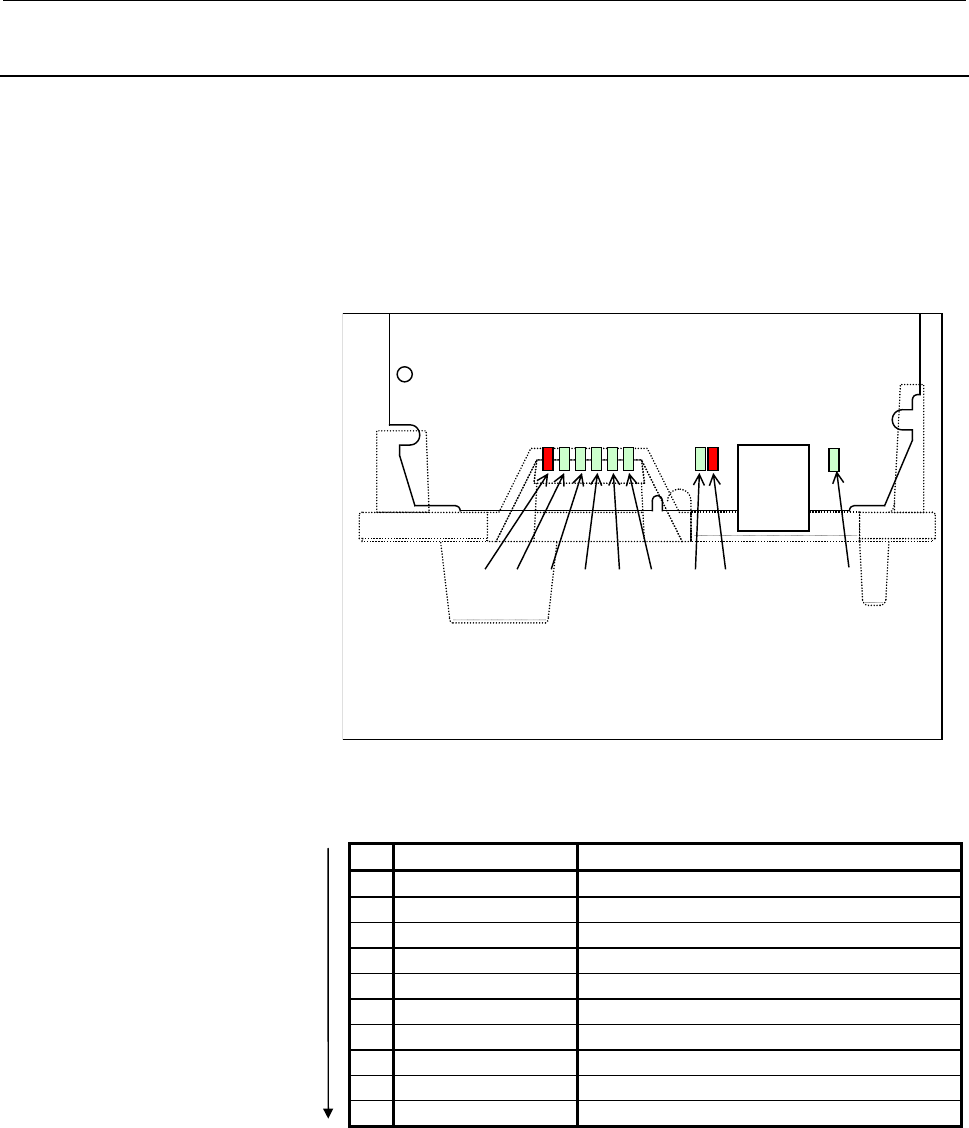
The Fast Ethernet board for Series 15i-B incorporates the following
LEDs: Four green STATUS LEDs and one red ALARM LED for
indicating the status. Two green LEDs and one red LED for indicating
the communication status. The figure below shows the locations of
these LEDs. The table below explains the LED lighting states.
In the following explanations, the LED lighting states are expressed as
follows:
o: Off n: On ¶: Blinking à: Don't care
CD38R
LED4 (Green)
LED3 (Green)
LED2 (Green)
LED1 (Green)
ALM (Red)
LIL (Green)
COL (Red)
COM (Green)
BTX (Green)
The dashed lines indicate the faceplate.
LED lighting sequence at power on
No. LED indication 1234 Fast Ethernet/Fast data server state
1 STATUS oooo Power off
2 STATUS nnnn Initial state after power on
3 STATUS nnno MPU initialized.
4 STATUS nnoo Firmware downloaded.
5 STATUS nooo Control migration to OS
6 STATUS onnn OS PHASE1
7 STATUS onno OS PHASE2
8 STATUS onon OS PHASE3
9 STATUS onoo OS PHASE4
10 STATUS ooo¶ Startup completed.
The system enters the No.10 status when the Fast Ethernet/Fast data
server starts normally. This status is maintained until an error occurs.
Contents Summary of Fast Ethernet Board/Fast Data Server Operators manual
- Page 1FANUC FAST Ethernet Board FANUC FAST DATA SERVER OPERATOR’S MANUAL B-63644EN/02
- Page 2- No part of this manual may be reproduced in any form. - All specifications and designs are subject to change without notice. The export of this product is subject to the authorization of the government of the country from where the product is exported. In this manual we have tried as much as possi
- Page 3B-63644EN/02 SAFETY PRECAUTIONS SAFETY PRECAUTIONS This section describes the safety precautions related to the use of CNC units, to ensure safe operation of machines fitted with FANUC CNC units. Read this section carefully before attempting to use any funcction described in this manaul. Users ahoul
- Page 4SAFETY PRECAUTIONS B-63644EN/02 1.1 DEFINITION OF WARNING, CAUTION, AND NOTE This manual includes safety precautions for protecting the user and preventing damage to the machine. Precautions are classified into Warnings and Cautions according to their bearing on safety. Also, supplementary informati
- Page 5B-63644EN/02 SAFETY PRECAUTIONS 1.2 GENERAL WARNINGS AND CAUTIONS WARNING 1 Before operating the machine, thoroughly check the entered data. Operating the machine with incorrectly specified data may result in the machine behaving unexpectedly, possibly causing damage to the workpiece and/or machine
- Page 6SAFETY PRECAUTIONS B-63644EN/02 CAUTION 1 Immediately after switching on the power, do not touch any of the keys on the MDI panel until the position display or alarm screen appears on the CNC unit. Some of the keys on the MDI panel are dedicated to maintenance or other special operations. Pressing a
- Page 7B-63644EN/02 TABLE OF CONTENTS TABLE OF CONTENTS SAFETY PRECAUTIONS .......................................................................... s-1 I. GENERAL 1 GENERAL ..............................................................................................3 1.1 ORGANIZATION....................
- Page 8TABLE OF CONTENTS B-63644EN/02 3.3 PARAMETERS ............................................................................................52 3.4 CONFIGURING A SMALL-SCALE NETWORK ...........................................53 3.5 CONFIGURING A LARGE-SCALE NETWORK .....................................
- Page 9B-63644EN/02 TABLE OF CONTENTS 4.1.1 Data Server Modes .............................................................................................. 114 4.1.2 Differences Between a File Number, O Number, and File Name ....................... 117 4.1.3 Entering a File Number, O Number, and File Name
- Page 10TABLE OF CONTENTS B-63644EN/02 4.8.2 Outputting the Parameter..................................................................................... 175 4.8.3 Inputting Tool Offsets ......................................................................................... 176 4.8.4 Outputting Tool Offs
- Page 11B-63644EN/02 TABLE OF CONTENTS 6.1.9 Data Server Screen Manipulation and Status Indication..................................... 222 6.2 HARD DISK FILE DIRECTORY SCREEN.................................................223 6.2.1 Displaying a List of Hard Disk Files .....................................
- Page 12TABLE OF CONTENTS B-63644EN/02 6.9 SELECTION OF HOST SCREEN..............................................................276 6.9.1 Checking the Connected Host ............................................................................. 277 6.9.2 Changing the Connected Host .........................
- Page 13B-63644EN/02 TABLE OF CONTENTS 4.5.1 Separating Signal Lines ....................................................................................... 314 4.5.2 Clamping and Shielding Cables .......................................................................... 314 4.5.3 Grounding the Network ....
- Page 14TABLE OF CONTENTS B-63644EN/02 2.5 CHECKING OPERATION STATUS OF EACH FUNCTION ......................357 APPENDIX A TROUBLESHOOTING .......................................................................363 A.1 CHECKING HUB CONNECTION ..............................................................364
- Page 15I. GENERA
- Page 16
- Page 17B-63644EN/02 I. GENERAL 1.GENERAL 1 GENERAL This part explains the organization of this manual. -3-
- Page 181.GENERAL I. GENERAL B-63644EN/02 1.1 Organization This manual consists of the following parts: SAFETY PRECAUTIONS This section describes the precautions to be observed when reading this manual. I GENERAL This section describes the chapter organization, applicable models, and related manuals. II SPE
- Page 19B-63644EN/02 I. GENERAL 1.GENERAL 1.2 Applicable Models This Operator's Manual covers the following models. The abbreviations in the following table are sometimes used in text descriptions. Product name Abbreviations FANUC Series 16i-TA 16i-TA Series 16i-A FANUC Series 16i-MA 16i-MA 16i FANUC Series
- Page 201.GENERAL I. GENERAL B-63644EN/02 1.3 Related Manuals The table below lists manuals related to this Operator's Manual. Refer to these manuals when you use this Operator's Manual. Series 16i/18i-TA/MA related manuals Manual name Specification number DESCRIPTIONS B-63002EN CONNECTION MANUAL (Hardware)
- Page 21B-63644EN/02 I. GENERAL 1.GENERAL Power Mate i -D/H related manuals Manual name Specification number DESCRIPTIONS B-63172EN CONNECTION MANUAL (Hardware) B-63173EN CONNECTION MANUAL (Function) B-63173EN-1 OPERATOR'S MANUAL B-63174EN MAINTENANCE MANUAL B-63175EN PARAMETER MANUAL B-63180EN Series 15i-M
- Page 22
- Page 23II. SPECIFICATIO
- Page 24
- Page 25B-63644EN/02 II. SPECIFICATION 1.ETHERNET FUNCTIONS 1 Function lists ETHERNET FUNCTIONS The Fast Ethernet board can use the following functions: Function name Applicable model FACTOLINK function Series 16i/18i/21i-A/B Series 16i/18i/21i-A/B DNC1/Ethernet function Power Mate i Series 16i/18i/21i-A/B
- Page 261.ETHERNET FUNCTIONS II. SPECIFICATION B-63644EN/02 1.1 FACTOLINK FUNCTION The FACTOLINK function displays a work instruction on the CNC screen or transfers NC data, using the NC. For details, refer to "FANUC FACTOLINK Script Function, OPERATOR'S MANUAL (B-75054EN)." Screen display You can display a
- Page 27B-63644EN/02 II. SPECIFICATION 1.ETHERNET FUNCTIONS 1.2 DNC1/Ethernet FUNCTION The DNC1/Ethernet function enables the remote control and monitoring of the CNC from a personal computer. For details, refer to "FANUC FA SYSTEM for PC WindowsNT Version, OPERATOR'S MANUAL (B-75044EN)." NC data transfer T
- Page 281.ETHERNET FUNCTIONS II. SPECIFICATION B-63644EN/02 1.3 FOCAS1/Ethernet FUNCTION The FOCAS1/Ethernet function enables the remote control and monitoring of the CNC from a personal computer. For details, refer to "FANUC Open CNC FOCAS1/Ethernet CNC/PMC Data Window Library." NC data transfer The follow
- Page 29B-63644EN/02 II. SPECIFICATION 1.ETHERNET FUNCTIONS Operation The following operation can be controlled remotely using a personal computer: • DNC operation Difference between the FOCAS1/Ethernet Function and DNC1/Ethernet Function - 15 -
- Page 301.ETHERNET FUNCTIONS II. SPECIFICATION B-63644EN/02 1.4 DATA SERVER FUNCTION The data server function uses FTP to transfer NC data or operate the DNC. This function is mainly used as an FTP client, but is also used as an FTP server. This function uses ATA flash card (ATA card) mounted on (connected
- Page 31B-63644EN/02 II. SPECIFICATION 1.ETHERNET FUNCTIONS Operation [ATA card on the Fast data server ↔ Tape memory] The following operations can be performed using the NC: • DNC operation • DNC operation by calling a subprogram (M198) Operation [Personal computer ↔ Tape memory] The following operations c
- Page 32
- Page 33III. SETTIN
- Page 34
- Page 35B-63644EN/02 III. SETTING 1.FACTOLINK FUNCTIONS FOR THE 16i/18i/21i 1 FACTOLINK FUNCTIONS FOR THE 16i/18i/21i This section describes the settings needed to use the FACTOLINK functions with the Series 16i/18i/21i-A/B. - 21 -
- Page 361.FACTOLINK FUNCTIONS FOR THE 16i/18i/21i III. SETTING B-63644EN/02 1.1 PRECAUTIONS WHEN USING THE ETHERNET BOARD FOR THE FIRST TIME CAUTION When the Fast Ethernet board is used for the first time, consult with your company's network administrator to determine the IP addresses and other settings. Th
- Page 37B-63644EN/02 III. SETTING 1.FACTOLINK FUNCTIONS FOR THE 16i/18i/21i 1.2 ETHERNET PARAMETER SCREEN The Ethernet Parameter screen is used to set the parameters that are needed to use the FACTOLINK functions. Display Procedure 1 Place the CNC in MDI mode. 2 Press function key SYSTEM . 3 Press the Conti
- Page 381.FACTOLINK FUNCTIONS FOR THE 16i/18i/21i III. SETTING B-63644EN/02 - 24 -
- Page 39B-63644EN/02 III. SETTING 1.FACTOLINK FUNCTIONS FOR THE 16i/18i/21i Display items and setting items Display items related to Ethernet functions Those items related to Ethernet functions are displayed. Item Description MAC ADDRESS MAC address of the Fast Ethernet board NUMBER OF Total number of Ether
- Page 401.FACTOLINK FUNCTIONS FOR THE 16i/18i/21i III. SETTING B-63644EN/02 Item Description IP ADDRESS 3 Specifies the IP address of the personal computer to be accessed by the FACTOLINK functions. (Format: "192.168.0.103") PORT NUMBER 3 Specifies the port No. to be used by the FACTOLINK functions within a
- Page 41B-63644EN/02 III. SETTING 1.FACTOLINK FUNCTIONS FOR THE 16i/18i/21i Entering data The following describes the basic method for entering data. Procedure 1 Place the CNC in MDI mode. 2 Display the "Ethernet Parameter" screen. 3 Position the cursor to the desired item by using the cursor movement keys.
- Page 421.FACTOLINK FUNCTIONS FOR THE 16i/18i/21i III. SETTING B-63644EN/02 (b) Enter "192.168.0.1" using the MDI keys. (c) Press soft key [INPUT] or function key INPUT to fix the data. This causes the parameters to be saved to the non-volatile memory of the CNC. - 28 -
- Page 43B-63644EN/02 III. SETTING 1.FACTOLINK FUNCTIONS FOR THE 16i/18i/21i 1.3 PARAMETERS The following describes the parameters related to the FACTOLINK functions. Parameters 0802 Communication channel [Data type] Byte [Valid data range] 11 to 13 11: Selects IP address 1. 12: Selects IP address 2. 13. Sel
- Page 441.FACTOLINK FUNCTIONS FOR THE 16i/18i/21i III. SETTING B-63644EN/02 0813 Length of logging data [Data type] Word [Unit of data] Number of bytes [Valid data range] 0 to 65535 Sets the length of the logging data. 0814 Logging trigger PMC address [Data type] Word [Valid data range] 0 to 65535 Sets the
- Page 45B-63644EN/02 III. SETTING 1.FACTOLINK FUNCTIONS FOR THE 16i/18i/21i 1.4 CONFIGURING A SMALL-SCALE NETWORK The following shows an example of the minimum settings needed to run the FACTOLINK functions on a small-scale network. These settings allow a personal computer to be connected to two CNCs, using
- Page 461.FACTOLINK FUNCTIONS FOR THE 16i/18i/21i III. SETTING B-63644EN/02 No.1 CNC No.2 CNC IP address 192.168.0.1 192.168.0.2 Subnet mask 255.255.255.0 255.255.255.0 Router IP address None None IP address 1 192.168.0.101 192.168.0.101 Port No.1 9000 9000 Set these items in the IP address 2 None None “Eth
- Page 47B-63644EN/02 III. SETTING 1.FACTOLINK FUNCTIONS FOR THE 16i/18i/21i 1.5 CONFIGURING A LARGE-SCALE NETWORK Before you configure a large-scale network or add such a network to an existing network, consult with your company's network administrator to determine IP addresses, subnet masks, and router IP
- Page 482.DNC1/Ethernet FUNCTIONS FOR THE 16i/18i/21i/PMi III. SETTING B-63644EN/02 2 DNC1/Ethernet FUNCTIONS FOR THE 16ii/18ii/21ii/PMii The following describes the settings needed to use the DNC1/Ethernet functions with the Series 16i/18i/21i-A/B and Power Mate i. - 34 -
- Page 49B-63644EN/02 III. SETTING 2.DNC1/Ethernet FUNCTIONS FOR THE 16i/18i/21i/PMi 2.1 PRECAUTIONS WHEN USING THE DNC1/Ethernet FOR THE FIRST TIME CAUTION When the Fast Ethernet board is used for the first time, consult with your company’s network administrator to determine the IP addresses and other setti
- Page 502.DNC1/Ethernet FUNCTIONS FOR THE 16i/18i/21i/PMi III. SETTING B-63644EN/02 2.2 ETHERNET PARAMETER SCREEN The Ethernet Parameter screen is used to set the parameters that are needed to use the DNC1/Ethernet functions. Display Procedure 1 Place the CNC in MDI mode. 2 Press function key SYSTEM . 3 Pre
- Page 51B-63644EN/02 III. SETTING 2.DNC1/Ethernet FUNCTIONS FOR THE 16i/18i/21i/PMi - 37 -
- Page 522.DNC1/Ethernet FUNCTIONS FOR THE 16i/18i/21i/PMi III. SETTING B-63644EN/02 Display items and setting items Display items related to the Ethernet functions The items related to the Ethernet functions are displayed. Item Description MAC ADDRESS MAC address of the Fast Ethernet board NUMBER OF Total n
- Page 53B-63644EN/02 III. SETTING 2.DNC1/Ethernet FUNCTIONS FOR THE 16i/18i/21i/PMi NOTE 1 When the "TCP/IP setting items for the CNC" have been changed, the power must be turned off then on again. 2 The value set for "TIME INTERVAL," described under "DNC1/Ethernet setting items," may cause the communicatio
- Page 542.DNC1/Ethernet FUNCTIONS FOR THE 16i/18i/21i/PMi III. SETTING B-63644EN/02 Entering data The following describes the basic method for entering data. Procedure 1 Place the CNC in MDI mode. 2 Display the "Ethernet Parameter" screen. 3 Position the cursor to the desired item using the cursor movement
- Page 55B-63644EN/02 III. SETTING 2.DNC1/Ethernet FUNCTIONS FOR THE 16i/18i/21i/PMi (b) Enter "192.168.0.1" using the MDI keys. (c) Press soft key [INPUT] or function key INPUT to fix the data. This causes the parameter to be saved into the non-volatile memory of the CNC. - 41 -
- Page 562.DNC1/Ethernet FUNCTIONS FOR THE 16i/18i/21i/PMi III. SETTING B-63644EN/02 2.3 PARAMETERS The following describes the parameter related to the DNC1/Ethernet functions. Parameter 0020 I/O CHANNEL: Selects the I/O device. [Data type] Byte [Valid data range] 0 to 35 6: Selects DNC1/Ethernet for the I/
- Page 57B-63644EN/02 III. SETTING 2.DNC1/Ethernet FUNCTIONS FOR THE 16i/18i/21i/PMi 2.4 CONFIGURING A SMALL-SCALE NETWORK The following shows an example of the minimum settings needed to use the DNC1/Ethernet functions with a small-scale network. These settings allow a personal computer to be connected to t
- Page 582.DNC1/Ethernet FUNCTIONS FOR THE 16i/18i/21i/PMi III. SETTING B-63644EN/02 2.5 CONFIGURING A LARGE-SCALE NETWORK Before you configure a large-scale network or add such a network to an existing network, consult with your company's network administrator to determine IP addresses, subnet masks, and ro
- Page 59B-63644EN/02 III. SETTING 3.FOCAS1/Ethernet FUNCTIONS FOR THE 16i/18i/21i/PMi 3 FOCAS1/Ethernet FUNCTIONS FOR THE 16i/18i/21i/PMi The following describes the settings needed to run the FOCAS1/Ethernet functions for the Series 16i/18i/21i-A/B and Power Mate i. - 45 -
- Page 603.FOCAS1/Ethernet FUNCTIONS FOR THE 16i/18i/21i/PMi III. SETTING B-63644EN/02 3.1 PRECAUTIONS TO BE OBSERVED WHEN USING THE FOCAS1/Ethernet FUNCTIONS FOR THE FIRST TIME CAUTION When the Fast Ethernet board is used for the first time, consult with your company’s network administrator to determine the
- Page 61B-63644EN/02 III. SETTING 3.FOCAS1/Ethernet FUNCTIONS FOR THE 16i/18i/21i/PMi 3.2 ETHERNET PARAMETER SCREEN The Ethernet Parameter screen is used to set parameters that are needed to run the FOCAS1/Ethernet functions. Display Procedure 1 Place the CNC in MDI mode. 2 Press function key SYSTEM . 3 Pre
- Page 623.FOCAS1/Ethernet FUNCTIONS FOR THE 16i/18i/21i/PMi III. SETTING B-63644EN/02 - 48 -
- Page 63B-63644EN/02 III. SETTING 3.FOCAS1/Ethernet FUNCTIONS FOR THE 16i/18i/21i/PMi Display items and setting items Display items related to the Ethernet functions The items related to the Ethernet functions are displayed. Item Description MAC ADDRESS MAC address of the Fast Ethernet board NUMBER OF Total
- Page 643.FOCAS1/Ethernet FUNCTIONS FOR THE 16i/18i/21i/PMi III. SETTING B-63644EN/02 Entering data The following describes the basic method for entering data. Procedure 1 Place the CNC in MDI mode. 2 Display the "Ethernet Parameter" screen. 3 Position the cursor to the desired item by using the cursor move
- Page 65B-63644EN/02 III. SETTING 3.FOCAS1/Ethernet FUNCTIONS FOR THE 16i/18i/21i/PMi (b) Enter "192.168.0.1" using the MDI keys. (c) Press soft key [INPUT] or function key INPUT to fix the data. This causes the parameter to be saved into the non-volatile memory of the CNC. - 51 -
- Page 663.FOCAS1/Ethernet FUNCTIONS FOR THE 16i/18i/21i/PMi III. SETTING B-63644EN/02 3.3 PARAMETERS The following describes the parameters related to the FOCAS1/Ethernet functions. Parameters 0020 I/O CHANNEL: Selects I/O device. [Data type] Byte [Unit of data] Bytes [Valid data range] 0 to 35 6: Selects F
- Page 67B-63644EN/02 III. SETTING 3.FOCAS1/Ethernet FUNCTIONS FOR THE 16i/18i/21i/PMi 3.4 CONFIGURING A SMALL-SCALE NETWORK The following shows an example of the minimum settings needed to run the FOCAS1/Ethernet functions on a small-scale network. These settings allow a personal computer to be connected to
- Page 683.FOCAS1/Ethernet FUNCTIONS FOR THE 16i/18i/21i/PMi III. SETTING B-63644EN/02 3.5 CONFIGURING A LARGE-SCALE NETWORK Before you configure a large-scale network or add such a network to an existing network, consult your company's network administrator to determine IP addresses, subnet masks, and route
- Page 69B-63644EN/02 III. SETTING 4.DATA SERVER FUNCTIONS FOR THE 16i/18i/21i 4 DATA SERVER FUNCTIONS FOR THE 16i/18i/21i The following describes the settings needed to run the data server functions for the Series 16i/18i/21i–A/B. - 55 -
- Page 704.DATA SERVER FUNCTIONS FOR THE 16i/18i/21i III. SETTING B-63644EN/02 4.1 PRECAUTIONS TO BE OBSERVED WHEN USING THE DATA SERVER FUNCTIONS FOR THE FIRST TIME CAUTION 1 When the Fast data server is used for the first time, format the ATA card, set the appropriate parameters, and turn the power off the
- Page 71B-63644EN/02 III. SETTING 4.DATA SERVER FUNCTIONS FOR THE 16i/18i/21i NOTE 1 One of the following option functions is needed when the data server functions are used: Series16i-TA A02B-0236-S737 Series 16i-MA A02B-0237-S737 Series 18i-TA A02B-0238-S737 Series 18i-MA A02B-0239-S737 Series 21i-TA A02B-
- Page 724.DATA SERVER FUNCTIONS FOR THE 16i/18i/21i III. SETTING B-63644EN/02 4.2 ETHERNET PARAMETER SCREEN The Ethernet Parameter screen is used to set the parameters that are needed for the data server functions. Display Procedure 1 Place the CNC in MDI mode. 2 Press function key SYSTEM . 3 Press the Cont
- Page 73B-63644EN/02 III. SETTING 4.DATA SERVER FUNCTIONS FOR THE 16i/18i/21i - 59 -
- Page 744.DATA SERVER FUNCTIONS FOR THE 16i/18i/21i III. SETTING B-63644EN/02 Display items and setting items Display items related to the Ethernet functions The items related to the Ethernet functions are displayed. Item Description MAC ADDRESS MAC address of the Fast data server NUMBER OF Total number of
- Page 75B-63644EN/02 III. SETTING 4.DATA SERVER FUNCTIONS FOR THE 16i/18i/21i Setting items for connected host 1, host 2, and host 3 Set the items related to the host computer on which the FTP server runs. Item Description PORT NUMBER Specifies the port No. to be used by the data server functions. Usually,
- Page 764.DATA SERVER FUNCTIONS FOR THE 16i/18i/21i III. SETTING B-63644EN/02 NOTE 1 When the "TCP/IP setting items for the CNC" have been changed, the power must be turned off then on again. 2 Note that the system differentiates between upper- and lower-case characters in "USERNAME" and "PASSWORD," describ
- Page 77B-63644EN/02 III. SETTING 4.DATA SERVER FUNCTIONS FOR THE 16i/18i/21i Entering data The following describes the basic method for entering data. Procedure 1 Place the CNC in MDI mode. 2 Display the "Ethernet Parameter" screen. 3 Position the cursor to the desired item by using the cursor movement key
- Page 784.DATA SERVER FUNCTIONS FOR THE 16i/18i/21i III. SETTING B-63644EN/02 (b) Enter "192.168.0.1" using the MDI keys. (c) Press soft key [INPUT] or function key INPUT to fix the data. This causes the parameter to be saved into the non-volatile memory of the CNC. - 64 -
- Page 79B-63644EN/02 III. SETTING 4.DATA SERVER FUNCTIONS FOR THE 16i/18i/21i Entering lowercase characters The following describes the method for entering lowercase characters. Procedure 1 Place the CNC in MDI mode. 2 Display the "Ethernet Parameter" screen. 3 Position the cursor to the desired item by usi
- Page 804.DATA SERVER FUNCTIONS FOR THE 16i/18i/21i III. SETTING B-63644EN/02 Entering long character strings The following describes the method for entering long character strings. In the following explanation, the string "/DATASERVER/NCPROGRAM/LINE001/GROUP0002" is entered as an example. Procedure 1 Place
- Page 81B-63644EN/02 III. SETTING 4.DATA SERVER FUNCTIONS FOR THE 16i/18i/21i 4 Press soft key [STRING]. The cursor position and soft key menu change as follows. 5 Enter "/DATASERVER/NCPROGRAM/LINE001/GR" using the MDI keys and then press soft key [INPUT]. - 67 -
- Page 824.DATA SERVER FUNCTIONS FOR THE 16i/18i/21i III. SETTING B-63644EN/02 6. Enter the subsequent part of the string, "OUP0002," using the MDI keys and then press soft key [INPUT]. [Reference] The character string can also be entered as different parts such as "/DATASERVER/NCPROGRAM" and "/LINE001/GROUP
- Page 83B-63644EN/02 III. SETTING 4.DATA SERVER FUNCTIONS FOR THE 16i/18i/21i 7 To insert "FACTORY0010" between "NCPROGRAM" and "LINE001," position the cursor to the "/" before "LINE001" and enter "/FACTORY0010" using the MDI keys. Then, press soft key [INSERT]. 8 To delete a character, position the cursor
- Page 844.DATA SERVER FUNCTIONS FOR THE 16i/18i/21i III. SETTING B-63644EN/02 10 Upon the completion of character string entry, press soft key [EXIT]. This operation returns the cursor and the soft key menu to the state shown under "Procedure 1." The data is saved into the non-volatile memory of the CNC. -
- Page 85B-63644EN/02 III. SETTING 4.DATA SERVER FUNCTIONS FOR THE 16i/18i/21i Entering special characters The following describes the method for entering special characters. In the following explanation, the string "PROG$" is entered as an example. Procedure 1 Place the CNC in MDI mode. 2 Display the "Ether
- Page 864.DATA SERVER FUNCTIONS FOR THE 16i/18i/21i III. SETTING B-63644EN/02 5 Press soft key [$]. 6 Press soft key [INPUT]. - 72 -
- Page 87B-63644EN/02 III. SETTING 4.DATA SERVER FUNCTIONS FOR THE 16i/18i/21i 4.3 PARAMETERS The following describes the parameters related to the data server functions. Parameters 0020 I/O CHANNEL: Selects an I/O device. [Data type] Byte [Valid data range] 0 to 35 5: Selects the data server for the I/O dev
- Page 884.DATA SERVER FUNCTIONS FOR THE 16i/18i/21i III. SETTING B-63644EN/02 923 Selects the host computer 3 OS. [Data type] Byte [Valid data range] 0 and 1 1: UNIX/VMS. 0: Windows 95/98/Me/NT/2000. 924 DNC1/Ethernet or FOCAS1/Ethernet wait time [Data type] Word [Unit of data] 1.1 ms [Valid data range] 0 t
- Page 89B-63644EN/02 III. SETTING 4.DATA SERVER FUNCTIONS FOR THE 16i/18i/21i 4.4 CONFIGURING A SMALL-SCALE NETWORK The following shows an example of the minimum settings needed to use the data server functions on a small-scale network. These settings allow a personal computer to be connected to two CNCs by
- Page 904.DATA SERVER FUNCTIONS FOR THE 16i/18i/21i III. SETTING B-63644EN/02 4.5 CONFIGURING A LARGE-SCALE NETWORK Before you configure a large-scale network or add such a network to an existing network, consult with your company's network administrator to determine IP addresses, subnet masks, and router I
- Page 91B-63644EN/02 III. SETTING 5.FOCAS1/Ethernet FUNCTIONS FOR THE 15i 5 FOCAS1/Ethernet FUNCTIONS FOR THE 15i The following describes the settings needed to run the FOCAS1/Ethernet functions for the Series 15i-B. - 77 -
- Page 925.FOCAS1/Ethernet FUNCTIONS FOR THE 15i III. SETTING B-63644EN/02 5.1 PRECAUTIONS TO BE OBSERVED WHEN USING THE FOCAS1/Ethernet FUNCTIONS FOR THE FIRST TIME CAUTION When the Fast Ethernet board is used for the first time, consult with your company’s network administrator to determine the IP addresse
- Page 93B-63644EN/02 III. SETTING 5.FOCAS1/Ethernet FUNCTIONS FOR THE 15i 5.2 ETHERNET PARAMETER SCREEN The Ethernet Parameter screen is used to set parameters that are needed to run the FOCAS1/Ethernet functions. Display Procedure 1 Place the CNC in MDI mode. 2 Press function key SYSTEM . 3 Press soft key
- Page 945.FOCAS1/Ethernet FUNCTIONS FOR THE 15i III. SETTING B-63644EN/02 - 80 -
- Page 95B-63644EN/02 III. SETTING 5.FOCAS1/Ethernet FUNCTIONS FOR THE 15i Display items and setting items Display items related to the Ethernet functions The items related to the Ethernet functions are displayed. Item Description MAC ADDRESS MAC address of the Fast Ethernet board TCP/IP setting items for th
- Page 965.FOCAS1/Ethernet FUNCTIONS FOR THE 15i III. SETTING B-63644EN/02 Entering data The following describes the basic method for entering data. Procedure 1 Place the CNC in MDI mode. 2 Display the "Ethernet Parameter" screen. 3 Position the cursor to the desired item by using the cursor movement keys. 4
- Page 97B-63644EN/02 III. SETTING 5.FOCAS1/Ethernet FUNCTIONS FOR THE 15i (b) Enter "192.168.0.1" using the MDI keys. (c) Press soft key [INPUT] or function key INPUT to fix the data. - 83 -
- Page 985.FOCAS1/Ethernet FUNCTIONS FOR THE 15i III. SETTING B-63644EN/02 (d) Press soft key [SAVE]. (e) Press soft key [EXEC]. This saves the parameters into the non-volatile memory of the CNC. - 84 -
- Page 99B-63644EN/02 III. SETTING 5.FOCAS1/Ethernet FUNCTIONS FOR THE 15i 5.3 PARAMETERS The following describes the parameters related to the FOCAS1/Ethernet functions. Parameters 0020 Interface number of input device for foreground [Input section] Setting input [Data type] Integer [Valid data range] 0 to
- Page 1005.FOCAS1/Ethernet FUNCTIONS FOR THE 15i III. SETTING B-63644EN/02 5.4 CONFIGURING A SMALL-SCALE NETWORK The following shows an example of the minimum settings needed to run the FOCAS1/Ethernet functions on a small-scale network. These settings allow a personal computer to be connected to two CNCs by
- Page 101B-63644EN/02 III. SETTING 5.FOCAS1/Ethernet FUNCTIONS FOR THE 15i 5.5 CONFIGURING A LARGE-SCALE NETWORK Before you configure a large-scale network or add such a network to an existing network, consult your company's network administrator to determine IP addresses, subnet masks, and router IP address
- Page 1026.DATA SERVER FUNCTIONS FOR THE 15i III. SETTING B-63644EN/02 6 DATA SERVER FUNCTIONS FOR THE 15i The following describes the settings needed to run the data server functions for the Series 15i-B. - 88 -
- Page 103B-63644EN/02 III. SETTING 6.DATA SERVER FUNCTIONS FOR THE 15i 6.1 PRECAUTIONS TO BE OBSERVED WHEN USING THE DATA SERVER FUNCTIONS FOR THE FIRST TIME CAUTION 1 When the Fast data server is used for the first time, format the ATA card, set the appropriate parameters, and turn the power off then on aga
- Page 1046.DATA SERVER FUNCTIONS FOR THE 15i III. SETTING B-63644EN/02 6.2 ETHERNET PARAMETER SCREEN The Ethernet Parameter screen is used to set the parameters needed for the data server functions. Display Procedure 1 Place the CNC in MDI mode. 2 Press function key SYSTEM . 3 Press soft key [CHAPTER]. 4 Whe
- Page 105B-63644EN/02 III. SETTING 6.DATA SERVER FUNCTIONS FOR THE 15i - 91 -
- Page 1066.DATA SERVER FUNCTIONS FOR THE 15i III. SETTING B-63644EN/02 Display items and setting items Items related to the Ethernet functions The items related to the Ethernet functions are displayed. Item Description MAC ADDRESS MAC address of the Fast data server TCP/IP setting items for the CNC Set the T
- Page 107B-63644EN/02 III. SETTING 6.DATA SERVER FUNCTIONS FOR THE 15i NOTE 1 When the "TCP/IP setting items for the CNC" have been changed, the power must be turned off then on again. 2 Note that the system differentiates between upper- and lower-case characters in "USERNAME" and "PASSWORD," described under
- Page 1086.DATA SERVER FUNCTIONS FOR THE 15i III. SETTING B-63644EN/02 Entering data The following describes the basic method for entering data. Procedure 1 Place the CNC in MDI mode. 2 Display the "Ethernet (Setting)" screen. 3 Position the cursor to the desired item using the cursor movement keys. 4 Enter
- Page 109B-63644EN/02 III. SETTING 6.DATA SERVER FUNCTIONS FOR THE 15i (b) Enter "192.168.0.1" using the MDI keys. (c) Press soft key [INPUT] or function key INPUT to fix the data. - 95 -
- Page 1106.DATA SERVER FUNCTIONS FOR THE 15i III. SETTING B-63644EN/02 (d) Press soft key [SAVE]. (e) Press soft key [EXEC]. This saves the parameters into the non-volatile memory of the CNC. - 96 -
- Page 111B-63644EN/02 III. SETTING 6.DATA SERVER FUNCTIONS FOR THE 15i 6.3 PARAMETERS The following describes the parameters related to the data server functions. 0020 Interface number of input device for foreground [Input section] Setting input [Data type] Integer [Valid data range] 0 to 16 14: Selects the
- Page 1126.DATA SERVER FUNCTIONS FOR THE 15i III. SETTING B-63644EN/02 5031 Wait time for FOCAS1/Ethernet [Data type] Word [Valid data range] 1.1ms [Valid data range] 0 to 32767 Specifies the wait time in 1.1 ms for each service of the FOCAS1/Ethernet when it is used together with the data server function. I
- Page 113B-63644EN/02 III. SETTING 6.DATA SERVER FUNCTIONS FOR THE 15i 6.4 CONFIGURING A SMALL-SCALE NETWORK The following shows an example of the minimum settings needed to use the data server functions on a small-scale network. These settings allow a personal computer to be connected to one CNC by the data
- Page 1146.DATA SERVER FUNCTIONS FOR THE 15i III. SETTING B-63644EN/02 6.5 CONFIGURING A LARGE-SCALE NETWORK Before you configure a large-scale network or add such a network to an existing network, consult with your company's network administrator to determine IP addresses, subnet masks, and router IP addres
- Page 115IV. OPERATIO
- Page 116
- Page 117B-63644EN/02 IV. OPERATION 1.16i/18i/21i FACTOLINK FUNCTIONS 1 16i/18i/21i FACTOLINK FUNCTIONS This section describes how to use the series 16i/18i/21i-A/B FACTOLINK functions. - 103 -
- Page 1181.16i/18i/21i FACTOLINK FUNCTIONS IV. OPERATION B-63644EN/02 1.1 FACTOLINK SCREEN Display Procedure 1 Press function key MESSAGE . 2 Press the continuation menu key at the right end of the soft key menu. 3 When you press soft key [FALINK], the FACTOLINK screen appears. The following is a sample FACT
- Page 119B-63644EN/02 IV. OPERATION 1.16i/18i/21i FACTOLINK FUNCTIONS 1.2 ETHERNET ERROR MESSAGE SCREEN If an error related to the FACTOLINK functions occurs, an error message appears on the error message screen dedicated to the Ethernet functions. Display Procedure 1 Press function key MESSAGE . 2 Press the
- Page 1201.16i/18i/21i FACTOLINK FUNCTIONS IV. OPERATION B-63644EN/02 Configuration The following titles are provided for the Ethernet error message screen: • FAST_ETH SYSTEM LOG screen • FAST_ETH TCP/IP LOG screen • FAST_ETH PARAMETER LOG screen • FAST_ETH FACTOLINK LOG screen - 106 -
- Page 121B-63644EN/02 IV. OPERATION 2.16i/18i/21i/PMi DNC1/Ethernet FUNCTIONS 2 16i/18i/21i/PMi DNC1/Ethernet FUNCTIONS This section describes how to use the Series 16i/18i/21i-A/B, Power Mate i , DNC1/Ethernet functions. - 107 -
- Page 1222.16i/18i/21i/PMi DNC1/Ethernet FUNCTIONS IV. OPERATION B-63644EN/02 2.1 ETHERNET ERROR MESSAGE SCREEN If an error related to the DNC1/Ethernet functions occurs, an error message appears on the error message screen dedicated to the Ethernet functions. Display Procedure 1 Press function key MESSAGE .
- Page 123B-63644EN/02 IV. OPERATION 2.16i/18i/21i/PMi DNC1/Ethernet FUNCTIONS Configuration The following titles are provided for the Ethernet error message screen: • FAST_ETH SYSTEM LOG screen • FAST_ETH TCP/IP LOG screen • FAST_ETH PARAMETER LOG screen • FAST_ETH FOCAS1 #0 LOG screen • FAST_ETH FOCAS1 #1 L
- Page 1243.16i/18i/21i/PMi FOCAS1/Ethernet FUNCTIONS IV. OPERATION B-63644EN/02 3 16i/18i/21i/PMi FOCAS1/Ethernet FUNCTIONS This section describes how to use the Series 16i/18i/21i-A/B and Power Mate i FOCAS1/Ethernet functions. - 110 -
- Page 125B-63644EN/02 IV. OPERATION 3.16i/18i/21i/PMi FOCAS1/Ethernet FUNCTIONS 3.1 ETHERNET ERROR MESSAGE SCREEN If an error occurs for the FOCAS1/Ethernet functions, an error message is displayed on the error message screen dedicated to the Ethernet functions. Display Procedure 1 Press function key MESSAGE
- Page 1263.16i/18i/21i/PMi FOCAS1/Ethernet FUNCTIONS IV. OPERATION B-63644EN/02 Configuration The following titles are provided for the Ethernet error message screen: • FAST_ETH SYSTEM LOG screen • FAST_ETH TCP/IP LOG screen • FAST_ETH PARAMETER LOG screen • FAST_ETH FOCAS1 #0 LOG screen • FAST_ETH FOCAS1 #1
- Page 127B-63644EN/02 IV. OPERATION 4.16i/18i DATA SERVER FUNCTIONS 4 16i/18i/21i DATA SERVER FUNCTIONS This section describes how to use the series 16i/18i/21i-A/B data server functions. - 113 -
- Page 1284.16i/18i DATA SERVER FUNCTIONS IV. OPERATION B-63644EN/02 4.1 RULES GOVERNING THE USE OF THE DATA SERVER FUNCTIONS This section describes the rules governing the use of the data server functions. 4.1.1 Data Server Modes The data server function can run in three modes when it transfers NC data (such
- Page 129B-63644EN/02 IV. OPERATION 4.16i/18i DATA SERVER FUNCTIONS FTP mode In the FTP mode, data is transferred between the host computer built-in hard disk and CNC part program storage. For example, DNC operations including a DNC operation by a subprogram call (M198) require that the related NC programs b
- Page 1304.16i/18i DATA SERVER FUNCTIONS IV. OPERATION B-63644EN/02 Buffer mode In the buffer mode, an NC program that is larger than the capacity of the Fast data server built-in ATA flash card can run more safely than in the FTP mode. To be specific, if an NC program that is too large to fit on the Fast da
- Page 131B-63644EN/02 IV. OPERATION 4.16i/18i DATA SERVER FUNCTIONS 4.1.2 Differences Between a File Number, O Number, and File Name This subsection explains the differentiation between a file number, O number, and file name described in this manual. • File number Used to identify a file (data) stored in the
- Page 1324.16i/18i DATA SERVER FUNCTIONS IV. OPERATION B-63644EN/02 4.1.4 Differences Between a Hard Disk File and Host File This subsection explains the differentiation between a hard disk file and host file described in this manual. • Hard disk file Stored on the ATA flash card of the CNC Fast data server
- Page 133B-63644EN/02 IV. OPERATION 4.16i/18i DATA SERVER FUNCTIONS 4.1.5 Hard Disk File Names The name of any file on the Fast data server built-in ATA card is represented using the 8.3 file name format (8 characters in the file name and 3 characters in the file name extension) originally adopted for MS-DOS
- Page 1344.16i/18i DATA SERVER FUNCTIONS IV. OPERATION B-63644EN/02 4.1.6 NC Program Format The NC program prepared by the host computer must conform to the format shown below. % TITLE ; O0001(COMMENT) ; . . . M30 ; % The NC program begins with % (start file mark). A comment (title, etc.) can be inserted, as
- Page 135B-63644EN/02 IV. OPERATION 4.16i/18i DATA SERVER FUNCTIONS 4.1.7 List File Formats Use one of the following list formats for the LIST-GET, LIST-PUT, and LIST-DELETE functions, which are described later. Format 1 % ; O0001(COMMENT) ; N111 ; N222 ; N333 ; : : N999 ; % Format 2 % ; O0001(COMMENT) ; N11
- Page 1364.16i/18i DATA SERVER FUNCTIONS IV. OPERATION B-63644EN/02 Specifications common to all formats <1> The list file begins with "%" (start file mark). <2> An O number must be specified in the next block. The list file must be named using the same O number. A comment enclosed in parentheses "(" and ")"
- Page 137B-63644EN/02 IV. OPERATION 4.16i/18i DATA SERVER FUNCTIONS Specifications of format 3 The specifications of the format-3 list files are as follows: <1> In this format, process files have an arbitrary name. It is assumed that each file has the same name when it is on the Fast data server built-in ATA
- Page 1384.16i/18i DATA SERVER FUNCTIONS IV. OPERATION B-63644EN/02 Restrictions on file names in the list file The following restrictions apply when file names are specified in the list file. <1> Only the following 76 different ASCII characters can be used in arbitrary file names. Digits 0 to 9 Lowercase le
- Page 139B-63644EN/02 IV. OPERATION 4.16i/18i DATA SERVER FUNCTIONS List file storage location The LIST-GET, LIST-PUT, and LIST-DELETE services are useful to manage more than one NC program in a group. The storage location for the list file varies depending on what service is to be executed. If the LIST-GET
- Page 1404.16i/18i DATA SERVER FUNCTIONS IV. OPERATION B-63644EN/02 4.1.8 Buffer Mode Specifications The buffer mode is designed to handle NC programs larger than the capacity of the Fast data server built-in ATA card. In this mode, the Fast data server built-in ATA card is used as a temporary, intermediate
- Page 141B-63644EN/02 IV. OPERATION 4.16i/18i DATA SERVER FUNCTIONS 4.1.8.1 How to use the buffer mode The buffer mode is designed to handle an NC program larger than the capacity of the Fast data server built-in ATA card. This mode can be used with DNC operations (Section 4.6) including a DNC operation by a
- Page 1424.16i/18i DATA SERVER FUNCTIONS IV. OPERATION B-63644EN/02 NOTE Even in the buffer mode, it is possible to newly register files on the Fast data server built-in ATA card, using operations such as "NC program GET" and "output to NC program." These operations, however, may cause a buffer mode DNC oper
- Page 143B-63644EN/02 IV. OPERATION 4.16i/18i DATA SERVER FUNCTIONS 4.1.8.2 How to divide an NC program into several files In buffer mode operations, the host computer must previously divide an NC program into several files and create a list of these files arranged in the sequence in which they are to be tra
- Page 1444.16i/18i DATA SERVER FUNCTIONS IV. OPERATION B-63644EN/02 NOTE 1 The size of files into which an NC program is divided should be 20 to 30 MB. If the size is very large, there will be much idle time before the DNC operation begins. If the size is very small, data may be interrupted between files, re
- Page 145B-63644EN/02 IV. OPERATION 4.16i/18i DATA SERVER FUNCTIONS 4.1.9 Data Server Screen Manipulation and Status Indication • Display during operation During operation, the status is displayed at the lower-right of the screen. • Display upon completion of the operation Upon the completion of this operati
- Page 1464.16i/18i DATA SERVER FUNCTIONS IV. OPERATION B-63644EN/02 Operation Screen Status CONECT 1, CONECT 2, Connection Host Change CONNECT CONECT3 screen FORMAT Data Server Maintenance FORMAT screen CHKDSK Data Server Maintenance HD CHECK screen INPUT Ethernet parameters screen SETTING - 132 -
- Page 147B-63644EN/02 IV. OPERATION 4.16i/18i DATA SERVER FUNCTIONS 4.2 HARD DISK FILE DIR SCREEN The Hard Disk File Dir screen is used to list the files on the Fast data server built-in ATA card. - 133 -
- Page 1484.16i/18i DATA SERVER FUNCTIONS IV. OPERATION B-63644EN/02 Display items • REGISTERED PROGRAMS Displays the number of files stored in the current work directory. • FREE DISK AREA Displays the amount of free space, in bytes, on the Fast data server built-in ATA card. • CURRENT DIRECTORY Displays the
- Page 149B-63644EN/02 IV. OPERATION 4.16i/18i DATA SERVER FUNCTIONS • PUT Transfers a single file from the Fast data server built-in ATA card to the host computer built-in hard disk. • MPUT Transfers two or more files from the Fast data server built-in ATA card to the host computer built-in hard disk. The fi
- Page 1504.16i/18i DATA SERVER FUNCTIONS IV. OPERATION B-63644EN/02 4.2.1 Displaying a List of Hard Disk Files Display a list of the files stored on the Fast data server built-in ATA card. Procedure 1 Press function key PROG . 2 Press the continuation menu key at the right end of the soft key menu. 3 When yo
- Page 151B-63644EN/02 IV. OPERATION 4.16i/18i DATA SERVER FUNCTIONS 4.2.2 Searching for a Hard Disk File Display a list of the files stored on the Fast data server built-in ATA card by using the specified file as the first. Specify the file with the file number or name. Procedure 1 Display the Hard Disk File
- Page 1524.16i/18i DATA SERVER FUNCTIONS IV. OPERATION B-63644EN/02 4.2.3 Deleting a Hard Disk File Delete files stored on the Fast data server built-in ATA card. Deleting a single file Procedure 1 Display the Hard Disk File Dir screen. 2 Press soft key [(OPRT)]. 3 Press soft key [F DEL]. 4 Enter the number
- Page 153B-63644EN/02 IV. OPERATION 4.16i/18i DATA SERVER FUNCTIONS Deleting two or more files Procedure 1 Display the Hard Disk File Dir screen. 2 Press soft key [(OPRT)]. 3 Press soft key [F DEL]. 4 Enter the names of the files (including wild cards) to be deleted using the MDI keys. [Input format]
- Page 1544.16i/18i DATA SERVER FUNCTIONS IV. OPERATION B-63644EN/02 4.2.4 Copying a Hard Disk File Copy files stored in the Fast data server built-in ATA card. Procedure 1 Display the Hard Disk File Dir screen. 2 Press soft key [(OPRT)]. 3 Press soft key [F COPY]. 4 Enter the number or name of the copy sourc
- Page 155B-63644EN/02 IV. OPERATION 4.16i/18i DATA SERVER FUNCTIONS 4.2.5 Changing a Hard Disk File Name Change the name of a file stored on the Fast data server built-in ATA card. Procedure 1 Display the Hard Disk File Dir screen. 2 Press soft key [(OPRT)]. 3 Press soft key [FD CHA]. 4 Enter the number or n
- Page 1564.16i/18i DATA SERVER FUNCTIONS IV. OPERATION B-63644EN/02 4.2.6 Creating a Directory on the ATA Card Create a directory (folder) on the Fast data server built-in ATA card. Procedure 1 Display the Hard Disk File Dir screen. 2 Press soft key [(OPRT)]. 3 Press the continuation menu key at the right en
- Page 157B-63644EN/02 IV. OPERATION 4.16i/18i DATA SERVER FUNCTIONS 4.2.7 Deleting a Directory from the ATA Card Delete a directory (folder) from the Fast data server built-in ATA card. Procedure 1 Display the Hard Disk File Dir screen. 2 Press soft key [(OPRT)]. 3 Press the continuation menu key at the righ
- Page 1584.16i/18i DATA SERVER FUNCTIONS IV. OPERATION B-63644EN/02 4.2.8 Moving to Another Directory on the ATA Card Changes the work directory on the Fast data server built-in ATA card. Procedure 1 Display the Hard Disk File Dir screen. 2 Press soft key [(OPRT)]. 3 Press the continuation menu key at the ri
- Page 159B-63644EN/02 IV. OPERATION 4.16i/18i DATA SERVER FUNCTIONS 4.2.9 Executing Hard Disk File PUT Using FTP, transfer files from the Fast data server built-in ATA card to the host computer built-in hard disk. Procedure 1 Display the Hard Disk File Dir screen. 2 Press soft key [(OPRT)]. 3 Press the conti
- Page 1604.16i/18i DATA SERVER FUNCTIONS IV. OPERATION B-63644EN/02 NOTE 1 The transfer source file number or name must be separated from the transfer destination file name by a comma (,). 2 The transfer destination file name and delimiter (,) can be omitted. In such a case, the transfer destination file nam
- Page 161B-63644EN/02 IV. OPERATION 4.16i/18i DATA SERVER FUNCTIONS 4.2.10 Executing Hard Disk File MPUT Using FTP and wild cards (*, ?), transfer two or more files at one time from the Fast data server built-in ATA card to the host computer built-in hard disk. Procedure 1 Display the Hard Disk File Dir scre
- Page 1624.16i/18i DATA SERVER FUNCTIONS IV. OPERATION B-63644EN/02 4.2.11 Executing Hard Disk File LIST-PUT Transfer files from the Fast data server built-in ATA card to the host computer built-in hard disk according to the contents of the list file, using the FTP. Procedure 1 Display the Hard Disk File Dir
- Page 163B-63644EN/02 IV. OPERATION 4.16i/18i DATA SERVER FUNCTIONS 4.2.12 Executing Hard Disk File LIST-DELETE Delete files from the Fast data server built-in ATA card according to the contents of the list file. Procedure 1 Display the Hard Disk File Dir screen. 2 Press soft key [(OPRT)]. 3 Press the contin
- Page 1644.16i/18i DATA SERVER FUNCTIONS IV. OPERATION B-63644EN/02 4.3 HOST FILE DIR SCREEN The Host File Dir screen is used to display a file list for the host computer built-in hard disk. NOTE 1 A file name containing kanji, hiragana, and katakana characters is not displayed correctly. 2 The number of pro
- Page 165B-63644EN/02 IV. OPERATION 4.16i/18i DATA SERVER FUNCTIONS NOTE The above HOST FILE DIR (detail) screen is one display example. The display contents depend on the specifications of the FTP server used by the host computer. Display items • REGISTERED PROGRAMS Displays the number of files registered w
- Page 1664.16i/18i DATA SERVER FUNCTIONS IV. OPERATION B-63644EN/02 Operations • SWITCH Switches between normal display and detailed display. • UPDATE Updates the display contents. • STOP Stops the [GET], [MGET], and [L-GET] operations. • DISPLAY Updates the screen using the file specified by the file number
- Page 167B-63644EN/02 IV. OPERATION 4.16i/18i DATA SERVER FUNCTIONS 4.3.1 Displaying a List of Host Files Display a list of files stored on the host computer built-in hard disk. Procedure 1 Press function key PROG . 2 Press the continuation menu key at the right end of the soft key menu. 3 When you press sof
- Page 1684.16i/18i DATA SERVER FUNCTIONS IV. OPERATION B-63644EN/02 4.3.2 Searching for a Host File Display a list of files stored on the host computer built-in hard disk by using the file specified with the file number as the first. Procedure 1 Display the Host File Dir screen. 2 Press soft key [(OPRT)]. 3
- Page 169B-63644EN/02 IV. OPERATION 4.16i/18i DATA SERVER FUNCTIONS 4.3.3 Deleting a Host File Delete files stored on the host computer built-in hard disk. Procedure 1 Display the Host File Dir screen. 2 Press soft key [(OPRT)]. 3 Press soft key [F DEL]. 4 Enter the number or name of the file to be deleted u
- Page 1704.16i/18i DATA SERVER FUNCTIONS IV. OPERATION B-63644EN/02 4.3.4 Executing Host File GET Using FTP, transfer files from the host computer built-in hard disk to the Fast data server built-in ATA card. Procedure 1 Display the Host File Dir screen. 2 Press soft key [(OPRT)]. 3 Press the continuation me
- Page 171B-63644EN/02 IV. OPERATION 4.16i/18i DATA SERVER FUNCTIONS NOTE 1 The number or name of a transfer source file must be separated from a transfer destination file name by a comma (,). 2 The transfer destination file name and delimiter "," can be omitted. In this case, the transfer destination file na
- Page 1724.16i/18i DATA SERVER FUNCTIONS IV. OPERATION B-63644EN/02 4.3.5 Executing Host File MGET Using wild cards (*, ?) and FTP, transfer two or more files at one time from the host computer built-in hard disk to the Fast data server built- in ATA card. Procedure 1 Display the Host File Dir screen. 2 Pres
- Page 173B-63644EN/02 IV. OPERATION 4.16i/18i DATA SERVER FUNCTIONS NOTE 1 Wild card interpretation depends on the host computer specifications. 2 If a work directory on the host computer built-in hard disk contains a subdirectory, and a wild card that can represent the subdirectory is used to specify a tran
- Page 1744.16i/18i DATA SERVER FUNCTIONS IV. OPERATION B-63644EN/02 4.3.6 Executing Host File LIST-GET Transfer files from the host computer built-in hard disk to the Fast data server built-in ATA card according to the contents of the list file, using the FTP. Procedure 1 Display the Host File Dir screen. 2
- Page 175B-63644EN/02 IV. OPERATION 4.16i/18i DATA SERVER FUNCTIONS 4.4 INPUTTING AN NC PROGRAM Input a file (NC program) from the Fast data server built-in ATA card or host computer built-in hard disk to the tape memory. For the Hard Disk File Dir screen or Host File Dir screen Procedure 1 Place the CNC in
- Page 1764.16i/18i DATA SERVER FUNCTIONS IV. OPERATION B-63644EN/02 [Example 1] Enter O0001.DAT to input file O0001.DAT from the Fast data server built-in ATA card to the tape memory. However, the O number to be input into tape memory depends on the O number described in file O0001.DAT. [Example 2] Enter O00
- Page 177B-63644EN/02 IV. OPERATION 4.16i/18i DATA SERVER FUNCTIONS For the program screen Procedure 1 Place the CNC in EDIT mode. 2 Press function key PROG . 3 Press the continuation menu key at the right end of the soft key menu. 4 When you press soft key [PRGRM], the Program screen is displayed. 5 Press s
- Page 1784.16i/18i DATA SERVER FUNCTIONS IV. OPERATION B-63644EN/02 4.5 OUTPUTTING AN NC PROGRAM A file (NC program) is output from the tape memory to the Fast data server built-in ATA card or host computer built-in hard disk. For the Hard Disk File Dir screen or Host File Dir screen Procedure 1 Place the CN
- Page 179B-63644EN/02 IV. OPERATION 4.16i/18i DATA SERVER FUNCTIONS For the program screen Procedure 1 Place the CNC in EDIT mode. 2 Press function key PROG . 3 Press the continuation menu key at the right end of the soft key menu. 4 When you press soft key [PRGRM], the Program screen appears. 5 Press soft k
- Page 1804.16i/18i DATA SERVER FUNCTIONS IV. OPERATION B-63644EN/02 4.6 DNC OPERATIONS DNC operation is performed using an NC program stored on the Fast data server built-in ATA card or on the host computer built-in hard disk. For DNC operation in storage mode Procedure 1 Place the CNC in RMT mode. 2 Display
- Page 181B-63644EN/02 IV. OPERATION 4.16i/18i DATA SERVER FUNCTIONS For DNC operation in FTP mode Procedure 1 Place the CNC in RMT mode. 2 Select the host number for the host holding a file list to be used for an DNC operation according to the procedure described in Subsection 4.9.2, "Reconnecting the Host,"
- Page 1824.16i/18i DATA SERVER FUNCTIONS IV. OPERATION B-63644EN/02 For DNC operation in buffer mode Procedure 1 Place the CNC in RMT mode. 2 Select the host number for the host holding a file list to be used for an DNC operation according to the procedure described in Subsection 4.9.2, "Reconnecting the Hos
- Page 183B-63644EN/02 IV. OPERATION 4.16i/18i DATA SERVER FUNCTIONS 4.7 DNC OPERATION BY A SUBPROGRAM CALL (M198) Format for calling a subprogram from the main program (1) For Series 15 command format M198P∆∆∆∆Lxxxx; ∆∆∆∆ : NC program number on the data server side (4-digit numeral following O of the O numbe
- Page 1844.16i/18i DATA SERVER FUNCTIONS IV. OPERATION B-63644EN/02 DNC operation by a subprogram call (M198) in the storage mode Procedure 1 Place the CNC in MEM mode. 2 Display the Hard Disk File Directory screen and move to the directory holding an NC program to be called by a subprogram. 3 Press soft key
- Page 185B-63644EN/02 IV. OPERATION 4.16i/18i DATA SERVER FUNCTIONS DNC operation by a subprogram call (M198) in the FTP mode Procedure 1 Place the CNC in MEM mode. 2 Select the host number for the host holding an NC program to be called by a subprogram according to the procedure described in Subsection 4.9.
- Page 1864.16i/18i DATA SERVER FUNCTIONS IV. OPERATION B-63644EN/02 DNC operation by a subprogram call (M198) in the buffer mode Procedure 1 Place the CNC in MEM mode. 2 Select the host number for the host holding a file list to be called by a subprogram according to the procedure described in Subsection 4.9
- Page 187B-63644EN/02 IV. OPERATION 4.16i/18i DATA SERVER FUNCTIONS 4.8 DATA INPUT/OUTPUT The data listed below can be transferred between the Fast data server and CNC. How to transfer the data is explained later. 1 NC parameter 2 Tool offset value 3 Custom macro value 4 Workpiece zero point offset value 5 P
- Page 1884.16i/18i DATA SERVER FUNCTIONS IV. OPERATION B-63644EN/02 4.8.1 Inputting the Parameter Input files (NC parameters) from the Fast data server built-in ATA card or host computer built-in hard disk to CNC memory. For the Parameter screen Procedure 1 Place the CNC in EDIT mode. 2 Press function key SY
- Page 189B-63644EN/02 IV. OPERATION 4.16i/18i DATA SERVER FUNCTIONS 4.8.2 Outputting the Parameter Output files (NC parameters) from CNC memory to the Fast data server built-in ATA card or host computer built-in hard disk. For the Parameter screen Procedure 1 Place the CNC in EDIT mode. 2 Press function key
- Page 1904.16i/18i DATA SERVER FUNCTIONS IV. OPERATION B-63644EN/02 4.8.3 Inputting Tool Offsets A file (tool offset value) is input from the Fast data server built-in ATA card or host computer built-in hard disk to the CNC memory. For the Tool Compensation screen Procedure 1 Place the CNC in EDIT mode. 2 Pr
- Page 191B-63644EN/02 IV. OPERATION 4.16i/18i DATA SERVER FUNCTIONS 4.8.4 Outputting Tool Offsets A file (tool offset value) is output from the CNC memory to the Fast data server built-in ATA card or host computer built-in hard disk. For the Tool Compensation screen Procedure 1 Place the CNC in EDIT mode. 2
- Page 1924.16i/18i DATA SERVER FUNCTIONS IV. OPERATION B-63644EN/02 4.8.5 Inputting Custom Macro Variables A file (custom macro variables) is input from the Fast data server built-in ATA card or host computer built-in hard disk to the CNC memory. Custom macro variable input is executed in the same way as for
- Page 193B-63644EN/02 IV. OPERATION 4.16i/18i DATA SERVER FUNCTIONS 4.8.6 Outputting Custom Macro Variables A file (custom macro variables) is output from the CNC memory to the Fast data server built-in ATA card or host computer built-in hard disk. For the Macro Variable screen Procedure 1 Place the CNC in E
- Page 1944.16i/18i DATA SERVER FUNCTIONS IV. OPERATION B-63644EN/02 4.8.7 Inputting Workpiece Origin Offsets A file (workpiece origin offset) is input from the Fast data server built-in ATA card or host computer built-in hard disk to the CNC memory. For the WORK COORDINATES screen Procedure 1 Place the CNC i
- Page 195B-63644EN/02 IV. OPERATION 4.16i/18i DATA SERVER FUNCTIONS 4.8.8 Outputting Workpiece Origin Offsets A file (workpiece origin offset) is output from the CNC memory to the Fast data server built-in ATA card or host computer built-in hard disk. For the WORK COORDINATES screen Procedure 1 Place the CNC
- Page 1964.16i/18i DATA SERVER FUNCTIONS IV. OPERATION B-63644EN/02 4.8.9 Inputting Pitch Error Compensation Data A file (pitch error compensation data) is output from the Fast data server built-in ATA card or host computer built-in hard disk to the CNC memory. For the PIT-ERROR SETTING screen Procedure 1 Pl
- Page 197B-63644EN/02 IV. OPERATION 4.16i/18i DATA SERVER FUNCTIONS 4.8.10 Outputting Pitch Error Compensation Data A file (pitch error compensation data) is output from the CNC memory to the Fast data server built-in ATA card or host computer built-in hard disk. For the PIT-ERROR SETTING screen Procedure 1
- Page 1984.16i/18i DATA SERVER FUNCTIONS IV. OPERATION B-63644EN/02 4.8.11 Inputting an M-Code Group A file (M-code group) is input from the Fast data server built-in ATA card or host computer built-in hard disk to the CNC memory. For the M-Code Group Setting screen Procedure 1 Place the CNC in EDIT mode. 2
- Page 199B-63644EN/02 IV. OPERATION 4.16i/18i DATA SERVER FUNCTIONS 4.8.12 Outputting an M-Code Group A file (M-code group) is output from the CNC memory to the Fast data server built-in ATA card or host computer built-in hard disk. For the M-Code Group Setting screen Procedure 1 Place the CNC in EDIT mode.
- Page 2004.16i/18i DATA SERVER FUNCTIONS IV. OPERATION B-63644EN/02 4.8.13 Inputting Operation History Data A file (operation history data) is input from the Fast data server built-in ATA card or host computer built-in hard disk to the CNC memory. For the Operation History screen Procedure 1 Place the CNC in
- Page 201B-63644EN/02 IV. OPERATION 4.16i/18i DATA SERVER FUNCTIONS 4.8.14 Outputting Operation History Data A file (operation history data) is output from the tape memory to the Fast data server built-in ATA card or host computer built-in hard disk. For the Operation History screen Procedure 1 Place the CNC
- Page 2024.16i/18i DATA SERVER FUNCTIONS IV. OPERATION B-63644EN/02 4.9 CONNECT HOST SCREEN The Connect Host screen is used to check or change the host computer on which the FTP server is running. Display items • PORT NO., IP ADRS, USERNAME, and LOGIN DIR Display the values set from the Ethernet Parameter sc
- Page 203B-63644EN/02 IV. OPERATION 4.16i/18i DATA SERVER FUNCTIONS 4.9.1 Checking the Connected Host Check the host computer on which the FTP server, or the communication destination of the current Fast data server, is running. Procedure 1 Press function key PROG . 2 Press the continuation menu key at the r
- Page 2044.16i/18i DATA SERVER FUNCTIONS IV. OPERATION B-63644EN/02 4.9.2 Changing the Connected Host Check the host computer on which the FTP server, or the communication destination of the current Fast data server, is running. Procedure 1 Press function key PROG . 2 Press the continuation menu key at the r
- Page 205B-63644EN/02 IV. OPERATION 4.16i/18i DATA SERVER FUNCTIONS 4.10 FTP SERVER FUNCTIONS Communication is possible with the FTP client that runs on the host computer (personal computer). NOTE 1 Five FTP clients can be connected to the FTP server. However, some FTP client software may internally attempt
- Page 2064.16i/18i DATA SERVER FUNCTIONS IV. OPERATION B-63644EN/02 4.11 MAINTENANCE OF DATA SERVER SCREEN The Maintenance of Data Server screen is used to format (initialize) a Fast data server built-in ATA card, check for ATA card errors, switch between data server modes, and display the error examination
- Page 207B-63644EN/02 IV. OPERATION 4.16i/18i DATA SERVER FUNCTIONS Operations • STORAGE Changes the current mode to the storage mode. • FTP Changes the current mode to the FTP mode. • BUFFER Changes the current mode to the buffer mode. - 193 -
- Page 2084.16i/18i DATA SERVER FUNCTIONS IV. OPERATION B-63644EN/02 4.11.1 Checking the ATA Card Check whether the ATA card contains a faulty sector. Procedure 1 Place the CNC in MDI mode. 2 Press function key SYSTEM . 3 Press the continuation menu key at the right end of the soft key menu. 4 When you press
- Page 209B-63644EN/02 IV. OPERATION 4.16i/18i DATA SERVER FUNCTIONS 4.11.2 Formatting the ATA Card Format (initialize) the ATA card. Procedure 1 Place the CNC in MDI mode. 2 Press function key SYSTEM . 3 Press the continuation menu key at the right end of the soft key menu. 4 When you press soft key [DS-MIN]
- Page 2104.16i/18i DATA SERVER FUNCTIONS IV. OPERATION B-63644EN/02 CAUTION 1 If the CNC power is turned off during ATA card formatting, the ATA card may be destroyed. Never turn off the CNC power while formatting the ATA card. 2 If the ATA card is formatted, all the files on the ATA card are erased. Back up
- Page 211B-63644EN/02 IV. OPERATION 4.16i/18i DATA SERVER FUNCTIONS 4.11.3 Switching Data Server Modes Switch data server modes. Procedure 1 Press function key SYSTEM . 2 Press the continuation menu key at the right end of the soft key menu. 3 When you press soft key [DS-MIN], the Maintenance of Data Server
- Page 2124.16i/18i DATA SERVER FUNCTIONS IV. OPERATION B-63644EN/02 4.11.4 Displaying Error Examination Data Display data as the key to error examination if an error occurs during DNC operation using the data server function, DNC operation by a subprogram call (M198), or NC program input. Procedure 1 Press f
- Page 213B-63644EN/02 IV. OPERATION 4.16i/18i DATA SERVER FUNCTIONS 4.12 ETHERNET ERROR MESSAGE SCREEN If an error related to the data server function occurs, an error message appears on the error message screen dedicated to the Ethernet functions. Display Procedure 1 Press function key MESSAGE . 2 Press the
- Page 2144.16i/18i DATA SERVER FUNCTIONS IV. OPERATION B-63644EN/02 Configuration The following titles are provided for the Ethernet Error Message screen: • FAST_ETH SYSTEM LOG screen • FAST_ETH TCP/IP LOG screen • FAST_ETH PARAMETER LOG screen • FAST_ETH FTP SERVER LOG screen • FAST_ETH DATA SERVER L LOG sc
- Page 215B-63644EN/02 IV. OPERATION 5.15i FOCAS1/Ethernet FUNCTIONS 5 15i FOCAS1/Ethernet FUNCTIONS This section describes how to use the Series 15i-BFOCAS1/Ethernet functions. - 201 -
- Page 2165.15i FOCAS1/Ethernet FUNCTIONS IV. OPERATION B-63644EN/02 5.1 ETHERNET ERROR MESSAGE SCREEN If the FOCAS1/Ethernet function causes an error, an error message appears on the error message screen specific to the Ethernet functions. Display items - Title list Lists all titles on the Ethernet error mes
- Page 217B-63644EN/02 IV. OPERATION 5.15i FOCAS1/Ethernet FUNCTIONS Display Procedure 1 Press function key MESSAGE . 2 Press soft key [CHAPTER]. 3 When you press soft key [ETHERNET LOG], the "Ethernet (Log)" screen appears. 4 Select the desired page using the PAGE PAGE page keys. [Reference] The latest error
- Page 2186.15ii DATA SERVER FUNCTIONS IV. OPERATION B-63644EN/02 6 15i DATA SERVER FUNCTIONS This section describes how to operate the Series 15i-B data server functions. - 204 -
- Page 219B-63644EN/02 IV. OPERATION 6.15ii DATA SERVER FUNCTIONS 6.1 RULES GOVERNING THE USE OF THE DATA SERVER FUNCTIONS This section describes the rules governing the use of the data server functions. 6.1.1 Data Server Modes The data server function can run in three modes when it transfers NC data (such as
- Page 2206.15ii DATA SERVER FUNCTIONS IV. OPERATION B-63644EN/02 FTP mode In the FTP mode, data is transferred between the host computer built-in hard disk and CNC part program storage. For example, DNC operations including a DNC operation by a subprogram call (M198) require that the related NC programs be s
- Page 221B-63644EN/02 IV. OPERATION 6.15ii DATA SERVER FUNCTIONS Buffer mode In the buffer mode, an NC program that is larger than the capacity of the Fast data server built-in ATA flash card can run more safely than in the FTP mode. To be specific, if an NC program that is too large to fit on the Fast data
- Page 2226.15ii DATA SERVER FUNCTIONS IV. OPERATION B-63644EN/02 6.1.2 Differences Between a File Number, O Number, and File Name This subsection explains the differentiation between a file number, O number, and file name described in this manual. • File number Used to identify a file (data) stored in the Fa
- Page 223B-63644EN/02 IV. OPERATION 6.15ii DATA SERVER FUNCTIONS 6.1.4 Differences Between a Hard Disk File and Host File This subsection explains the differentiation between a hard disk file and host file described in this manual. • Hard disk file Stored on the ATA flash card of the CNC Fast data server (he
- Page 2246.15ii DATA SERVER FUNCTIONS IV. OPERATION B-63644EN/02 6.1.5 Hard Disk File Names The name of any file on the Fast data server built-in ATA card is represented using the 8.3 file name format (8 characters in the file name and 3 characters in the file name extension) originally adopted for MS-DOS. I
- Page 225B-63644EN/02 IV. OPERATION 6.15ii DATA SERVER FUNCTIONS 6.1.6 NC Program Format The NC program prepared by the host computer must conform to the format shown below. % TITLE ; O0001(COMMENT) ; . . . M30 ; % The NC program begins with % (start file mark). A comment (title, etc.) can be inserted, as re
- Page 2266.15ii DATA SERVER FUNCTIONS IV. OPERATION B-63644EN/02 6.1.7 List File Formats Use one of the following list formats for the LIST-GET, LIST-PUT, and LIST-DELETE functions, which are described later. Format 1 % ; O0001(COMMENT) ; N111 ; N222 ; N333 ; : : N999 ; % Format 2 % ; O0001(COMMENT) ; N111 (
- Page 227B-63644EN/02 IV. OPERATION 6.15ii DATA SERVER FUNCTIONS Specifications common to all formats <1> The list file begins with "%" (start file mark). <2> An O number must be specified in the next block. The list file must be named using the same O number. A comment enclosed in parentheses "(" and ")" ca
- Page 2286.15ii DATA SERVER FUNCTIONS IV. OPERATION B-63644EN/02 Specifications of format 3 The specifications of the format-3 list files are as follows: <1> In this format, process files have an arbitrary name. It is assumed that each file has the same name when it is on the Fast data server built-in ATA ca
- Page 229B-63644EN/02 IV. OPERATION 6.15ii DATA SERVER FUNCTIONS Restrictions on file names in the list file The following restrictions apply when file names are specified in the list file. <1> Only the following 76 different ASCII characters can be used in arbitrary file names. Digits 0 to 9 Lowercase lette
- Page 2306.15ii DATA SERVER FUNCTIONS IV. OPERATION B-63644EN/02 List file storage location The LIST-GET, LIST-PUT, and LIST-DELETE services are useful to manage more than one NC program in a group. The storage location for the list file varies depending on what service is to be executed. If the LIST-GET ser
- Page 231B-63644EN/02 IV. OPERATION 6.15ii DATA SERVER FUNCTIONS 6.1.8 Buffer Mode Specifications The buffer mode is designed to handle NC programs larger than the capacity of the Fast data server built-in ATA card. In this mode, the Fast data server built-in ATA card is used as a temporary, intermediate buf
- Page 2326.15ii DATA SERVER FUNCTIONS IV. OPERATION B-63644EN/02 6.1.8.1 How to use the buffer mode The buffer mode is designed to handle an NC program larger than the capacity of the Fast data server built-in ATA card. This mode can be used with DNC operations (Section 6.6) including a DNC operation by a su
- Page 233B-63644EN/02 IV. OPERATION 6.15ii DATA SERVER FUNCTIONS NOTE Even in the buffer mode, it is possible to newly register files on the Fast data server built-in ATA card, using operations such as "NC program GET" and "output to NC program." These operations, however, may cause a buffer mode DNC operati
- Page 2346.15ii DATA SERVER FUNCTIONS IV. OPERATION B-63644EN/02 6.1.8.2 How to divide an NC program into several files In buffer mode operations, the host computer must previously divide an NC program into several files and create a list of these files arranged in the sequence in which they are to be transf
- Page 235B-63644EN/02 IV. OPERATION 6.15ii DATA SERVER FUNCTIONS NOTE 1 The size of files into which an NC program is divided should be 20 to 30 MB. If the size is very large, there will be much idle time before the DNC operation begins. If the size is very small, data may be interrupted between files, resul
- Page 2366.15ii DATA SERVER FUNCTIONS IV. OPERATION B-63644EN/02 6.1.9 Data Server Screen Manipulation and Status Indication • Display during operation During operation, the status is displayed at the top of the screen. • Display at the end of operation Upon the completion of operation, the status is display
- Page 237B-63644EN/02 IV. OPERATION 6.15ii DATA SERVER FUNCTIONS 6.2 HARD DISK FILE DIRECTORY SCREEN The File Directory screen is used to display a list of files on the Fast data server built-in ATA card. - 223 -
- Page 2386.15ii DATA SERVER FUNCTIONS IV. OPERATION B-63644EN/02 Display items • DNC FILE NAME Displays the file name for which DNC operation is performed. • M198 DIRECTORY Displays the directory for DNC operation to be performed by a subprogram call (M198). • CURRENT DIR Displays the current work directory
- Page 239B-63644EN/02 IV. OPERATION 6.15ii DATA SERVER FUNCTIONS • MPUT Transfers two or more files from the Fast data server built-in ATA card to the host computer built-in hard disk. Wild cards (*, ?) can be used to specify file names. • PUT LIST Transfers files from the Fast data server built-in ATA card
- Page 2406.15ii DATA SERVER FUNCTIONS IV. OPERATION B-63644EN/02 6.2.1 Displaying a List of Hard Disk Files Display a list of files stored on the Fast data server built-in ATA card. Procedure 1 Press function key PROG . 2 Press soft key [CHAPTER]. 3 When you press [HDD DIR.], the Hard Disk File Directory scr
- Page 241B-63644EN/02 IV. OPERATION 6.15ii DATA SERVER FUNCTIONS 6.2.2 Searching for a Hard Disk File To display a list of files stored on the Fast data server built-in ATA card, select the first file by specifying its number or name. Procedure 1 Display the Hard Disk File Directory screen. 2 Press the opera
- Page 2426.15ii DATA SERVER FUNCTIONS IV. OPERATION B-63644EN/02 6.2.3 Deleting a Hard Disk File Delete a file stored on the Fast data server built-in ATA card. To delete a single file: Procedure 1 Display the Hard Disk File Directory screen. 2 Press the operation menu key at the right end of the soft key me
- Page 243B-63644EN/02 IV. OPERATION 6.15ii DATA SERVER FUNCTIONS To delete two or more files Procedure 1 Display the Hard Disk File Directory screen. 2 Press the operation menu key at the right end of the soft key menu. 3 Press soft key [DEL FILE]. 4 Using the MDI keys, enter the name of the file to be delet
- Page 2446.15ii DATA SERVER FUNCTIONS IV. OPERATION B-63644EN/02 6.2.4 Copying a Hard Disk File Copy a file stored on the Fast data server built-in ATA card. Procedure 1 Display the Hard Disk File Directory screen. 2 Press the operation menu key at the right end of the soft key menu. 3 Press soft key [COPY F
- Page 245B-63644EN/02 IV. OPERATION 6.15ii DATA SERVER FUNCTIONS 6.2.5 Changing a Hard Disk File Name Change the name of a file stored on the Fast data server built-in ATA card. Procedure 1 Display the Hard Disk File Directory screen. 2 Press the operation menu key at the right end of the soft key menu. 3 Pr
- Page 2466.15ii DATA SERVER FUNCTIONS IV. OPERATION B-63644EN/02 6.2.6 Creating a Directory on the ATA Card Create a directory(folder) on the Fast data server built-in ATA card. Procedure 1 Display the Hard Disk File Directory screen. 2 Press the operation menu key at the right end of the soft key menu. 3 Pr
- Page 247B-63644EN/02 IV. OPERATION 6.15ii DATA SERVER FUNCTIONS 6.2.7 Deleting a Directory from the ATA Card Delete a directory(folder) from the Fast data server built-in ATA card. Procedure 1 Display the Hard Disk File Directory screen. 2 Press the operation menu key at the right end of the soft key menu.
- Page 2486.15ii DATA SERVER FUNCTIONS IV. OPERATION B-63644EN/02 6.2.8 Moving a Directory on the ATA Card Move a work directory on the Fast data server built-in ATA card. Procedure 1 Display the Hard Disk File Directory screen. 2 Press the operation menu key at the right end of the soft key menu. 3 Press sof
- Page 249B-63644EN/02 IV. OPERATION 6.15ii DATA SERVER FUNCTIONS 6.2.9 Executing Hard Disk File PUT Using FTP, transfer a file from the Fast data server built-in ATA card to the host computer built-in hard disk. Procedure 1 Display the Hard Disk File Directory screen. 2 Press the operation menu key at the ri
- Page 2506.15ii DATA SERVER FUNCTIONS IV. OPERATION B-63644EN/02 [Example] This example explains how to move file O0001.DAT, with file name PROG1.DAT, from the Fast data server built-in ATA card and put it on the host computer built-in hard disk. 1. Press soft key [PUT]. 2. Enter the transfer source file nam
- Page 251B-63644EN/02 IV. OPERATION 6.15ii DATA SERVER FUNCTIONS C. Cursor Position the cursor to the transfer source file. Press soft key [(CURSOR)]. 3. Enter the transfer destination file name. If the transfer destination name is omitted, the transfer source file name is used. Press soft key [,"FILE NAME].
- Page 2526.15ii DATA SERVER FUNCTIONS IV. OPERATION B-63644EN/02 6.2.10 Executing Hard Disk File MPUT Using wild cards (*, ?) and FTP, transfer two or more files from the Fast data server built-in ATA card to the host computer built-in hard disk. Procedure 1 Display the Hard Disk File Directory screen. 2 Pre
- Page 253B-63644EN/02 IV. OPERATION 6.15ii DATA SERVER FUNCTIONS 6.2.11 Executing Hard Disk File LIST-PUT Transfer files from the Fast data server built-in ATA card to the host computer built-in hard disk according to the contents of the list file, using the FTP. Procedure 1 Display the Hard Disk File Dir sc
- Page 2546.15ii DATA SERVER FUNCTIONS IV. OPERATION B-63644EN/02 6.2.12 Executing Hard Disk File LIST-DELETE Delete files from the Fast data server built-in ATA card according to the contents of the list file. Procedure 1 Display the Hard Disk File Dir screen. 2 Press the operation menu key at the right end
- Page 255B-63644EN/02 IV. OPERATION 6.15ii DATA SERVER FUNCTIONS 6.3 HOST DIRECTORY SCREEN The Host Directory screen is used to display a list of the files stored on the host computer built-in hard disk. NOTE 1 A file name containing kanji, hiragana, and katakana characters is not displayed correctly. 2 The
- Page 2566.15ii DATA SERVER FUNCTIONS IV. OPERATION B-63644EN/02 NOTE The above Host Directory (Detail) screen is one display example. The display contents depend on the specifications of the FTP server used by the host computer. - 242 -
- Page 257B-63644EN/02 IV. OPERATION 6.15ii DATA SERVER FUNCTIONS Display items • DNC HOST Displays the host number for DNC operation. • DNC FILE NAME Displays the file name for DNC operation. • M198 HOST Displays the host number for DNC operation by a subprogram call (M198). • CURRENT HOST Displays the numbe
- Page 2586.15ii DATA SERVER FUNCTIONS IV. OPERATION B-63644EN/02 • DEL FILE Deletes files from the host computer built-in hard disk. • CHANGE HOST Switches the current screen to the Connection Host screen. • REDRAW SCRN Updates the Host Directory screen. • CHANGE SCRN Switches between normal display and deta
- Page 259B-63644EN/02 IV. OPERATION 6.15ii DATA SERVER FUNCTIONS 6.3.1 Displaying a List of Host Files Display a list of the files stored on the host computer built-in hard disk. Procedure 1 Press function key PROG . 2 Press soft key [CHAPTER]. 3 When you press soft key [HOST DIR.], the Host Directory screen
- Page 2606.15ii DATA SERVER FUNCTIONS IV. OPERATION B-63644EN/02 6.3.2 Searching for a Host File To display a list of files stored on the host computer built-in hard disk, specify the file number of the first file. Procedure 1 Display the Host Directory screen. 2 Press the operation menu key at the right end
- Page 261B-63644EN/02 IV. OPERATION 6.15ii DATA SERVER FUNCTIONS 6.3.3 Deleting a Host File Delete a file from the host computer built-in hard disk. Procedure 1 Display the Host Directory screen. 2 Press the operation menu key at the right end of the soft key menu. 3 Press soft key [DEL FILE]. 4 Using the MD
- Page 2626.15ii DATA SERVER FUNCTIONS IV. OPERATION B-63644EN/02 6.3.4 Executing Host File GET Using FTP, transfer a file from the host computer built-in hard disk to the Fast data server built-in ATA card. Procedure 1 Display the Host Directory screen. 2 Press the operation menu key at the right end of the
- Page 263B-63644EN/02 IV. OPERATION 6.15ii DATA SERVER FUNCTIONS NOTE 1 A transfer destination file name can be omitted. In this case, the transfer source file name is used. 2 If an error occurs, determine the cause of the error by referring to the Ethernet Error Message screen. 3 As the transfer destination
- Page 2646.15ii DATA SERVER FUNCTIONS IV. OPERATION B-63644EN/02 6.3.5 Executing Host File MGET Using wild cards (*, ?) and FTP, transfer two or more files at one time from the host computer built-in hard disk to the Fast data server built- in ATA card. Procedure 1 Display the Host Directory screen. 2 Press
- Page 265B-63644EN/02 IV. OPERATION 6.15ii DATA SERVER FUNCTIONS 6.3.6 Executing Host File LIST-GET Transfer files from the host computer built-in hard disk to the Fast data server built-in ATA card according to the contents of the list file, using the FTP. Procedure 1 Display the Host File Dir screen. 2 Pre
- Page 2666.15ii DATA SERVER FUNCTIONS IV. OPERATION B-63644EN/02 6.4 INPUTTING AN NC PROGRAM Input a file (NC program) from the Fast data server built-in ATA card or host computer built-in hard disk to tape memory. For the Hard Disk File Directory screen or Host Directory screen Procedure 1 In storage mode,
- Page 267B-63644EN/02 IV. OPERATION 6.15ii DATA SERVER FUNCTIONS [Example] To input file O0001.DAT from the Fast data server built-in ATA card to tape memory, enter O0001.DAT. However, the O number to be input to tape memory depends on that described in file O0001.DAT. NOTE 1 An NC program cannot be input co
- Page 2686.15ii DATA SERVER FUNCTIONS IV. OPERATION B-63644EN/02 For the Program (Edit) screen Procedure 1 Place the CNC in EDIT mode. 2 Press function key PROG . 3 Press soft key [CHAPTER]. 4 When you press soft key [TXT], the Program (Edit) screen appears. 5 Press the operation menu key at the right end of
- Page 269B-63644EN/02 IV. OPERATION 6.15ii DATA SERVER FUNCTIONS 6.5 OUTPUTTING AN NC PROGRAM A file (NC program) is output from tape memory to the Fast data server built-in ATA card or host computer built-in hard disk. For the Hard Disk File Directory screen or Host Directory screen Procedure 1 In storage m
- Page 2706.15ii DATA SERVER FUNCTIONS IV. OPERATION B-63644EN/02 For the Program (Edit) screen Procedure 1 Place the CNC in EDIT mode. 2 Press function key PROG . 3 Press soft key [CHAPTER]. 4 When you press [TXT], the Program (Edit) screen appears. 5 Press the operation menu key at the right end of the soft
- Page 271B-63644EN/02 IV. OPERATION 6.15ii DATA SERVER FUNCTIONS 6.6 DNC OPERATIONS DNC operation is performed by using an NC program stored on the Fast data server built-in ATA card or on the host computer built-in hard disk. For DNC operation in storage mode Procedure 1 Place the CNC in DNC mode. 2 Display
- Page 2726.15ii DATA SERVER FUNCTIONS IV. OPERATION B-63644EN/02 For DNC operation in FTP mode Procedure 1 Place the CNC in DNC mode. 2 Select the host number for the host holding a file list to be used for an DNC operation according to the procedure described in Subsection 6.9.2, "Reconnecting the Host," to
- Page 273B-63644EN/02 IV. OPERATION 6.15ii DATA SERVER FUNCTIONS For DNC operation in buffer mode Procedure 1 Place the CNC in DNC mode. 2 Select the host number for the host holding a file list to be used for an DNC operation according to the procedure described in Subsection 6.9.2, "Reconnecting the Host,"
- Page 2746.15ii DATA SERVER FUNCTIONS IV. OPERATION B-63644EN/02 6.7 DNC OPERATION BY A SUBPROGRAM CALL (M198) • Format for calling a subprogram from the main program (1) For the Series 15 directive format M198P∆∆∆∆∆∆∆∆Loooo; ∆∆∆∆∆∆∆∆ : NC program number on the hard disk (8-digit numeral following O of the O
- Page 275B-63644EN/02 IV. OPERATION 6.15ii DATA SERVER FUNCTIONS For DNC operation by a subprogram call (M198) in storage mode Procedure 1 Place the CNC in MEM mode. 2 Display the Hard Disk File Directory screen and move to the directory holding an NC program to be called by a subprogram. 3 Press the operati
- Page 2766.15ii DATA SERVER FUNCTIONS IV. OPERATION B-63644EN/02 DNC operation by a subprogram call (M198) in FTP mode Procedure 1 Place the CNC in MEM mode. 2 Select the host number for the host holding an NC program to be called by a subprogram according to the procedure described in Subsection 6.9.2, "Rec
- Page 277B-63644EN/02 IV. OPERATION 6.15ii DATA SERVER FUNCTIONS DNC operation by a subprogram call (M198) in buffer mode Procedure 1 Place the CNC in MEM mode. 2 Select the host number for the host holding an NC program to be called by a subprogram according to the procedure described in Subsection 6.9.2, "
- Page 2786.15ii DATA SERVER FUNCTIONS IV. OPERATION B-63644EN/02 6.8 DATA INPUT/OUTPUT The data listed below can be transferred between the Fast data server and CNC. How to transfer the data is explained later. 1 NC parameter 2 Tool offset value 3 Custom macro value 4 Workpiece zero point offset value 5 Pitc
- Page 279B-63644EN/02 IV. OPERATION 6.15ii DATA SERVER FUNCTIONS 6.8.1 Inputting Parameters A file (parameter) is input from the Fast data server built-in ATA card or host computer built-in hard disk to tape memory. For the Parameter screen Procedure 1 Place the CNC in the emergency stop status. 2 Press func
- Page 2806.15ii DATA SERVER FUNCTIONS IV. OPERATION B-63644EN/02 6.8.2 Outputting Parameters A file (parameters) is output from the tape memory to the Fast data server built-in ATA card or host computer built-in hard disk. To the Parameter screen Procedure 1 Press function key SYSTEM . 2 Press soft key [CHAP
- Page 281B-63644EN/02 IV. OPERATION 6.15ii DATA SERVER FUNCTIONS 6.8.3 Inputting Tool Offsets A file (tool offset values) is input from the Fast data server built-in ATA card or host computer built-in hard disk to the tape memory. For the Tool Offset screen Procedure 1 Place the CNC in MDI mode. 2 Press func
- Page 2826.15ii DATA SERVER FUNCTIONS IV. OPERATION B-63644EN/02 6.8.4 Outputting Tool Offsets A file (tool offset values) is output from tape memory to the Fast data server built-in ATA card or host computer built-in hard disk. For the Tool Offset screen Procedure 1 Press function key OFFSET SETTING . 2 Pre
- Page 283B-63644EN/02 IV. OPERATION 6.15ii DATA SERVER FUNCTIONS 6.8.5 Inputting Custom Macro Variables A file (custom macro variables) is output from the Fast data server built-in ATA card or host computer built-in hard disk to tape memory. For the Custom Macro screen Procedure 1 Place the CNC in MDI mode.
- Page 2846.15ii DATA SERVER FUNCTIONS IV. OPERATION B-63644EN/02 6.8.6 Outputting Custom Macro Variables A file (custom macro variables) is output from tape memory to the Fast data server built-in ATA card or host computer built-in hard disk. For the Custom Macro screen Procedure 1 Press function key OFFSET
- Page 285B-63644EN/02 IV. OPERATION 6.15ii DATA SERVER FUNCTIONS 6.8.7 Inputting Workpiece Origin Offsets A file (workpiece origin offset) is input from the Fast data server built-in ATA card or host computer built-in hard disk to tape memory. For the Workpiece Origin Offset screen Procedure 1 Place the CNC
- Page 2866.15ii DATA SERVER FUNCTIONS IV. OPERATION B-63644EN/02 6.8.8 Outputting Workpiece Origin Offsets A file (workpiece origin offset) is output from tape memory to the Fast data server built-in ATA card or host computer built-in hard disk. For the Workpiece Offset screen Procedure 1 Press function key
- Page 287B-63644EN/02 IV. OPERATION 6.15ii DATA SERVER FUNCTIONS 6.8.9 Inputting Pitch Error Compensation Data A file (pitch error compensation data) is input from the Fast data server built-in ATA card or host computer built-in hard disk to tape memory. For the Pitch Error Compensation screen Procedure 1 Pl
- Page 2886.15ii DATA SERVER FUNCTIONS IV. OPERATION B-63644EN/02 6.8.10 Outputting Pitch Error Compensation Data A file (pitch error compensation data) is output from tape memory to the Fast data server built-in ATA card or host computer built-in hard disk. For the Pitch Error Compensation screen Procedure 1
- Page 289B-63644EN/02 IV. OPERATION 6.15ii DATA SERVER FUNCTIONS 6.8.11 Outputting Operation History Data A file (operation history data) is output from tape memory to the Fast data server built-in ATA card or host computer built-in hard disk. To the Operation History screen Procedure 1 Press function key SY
- Page 2906.15ii DATA SERVER FUNCTIONS IV. OPERATION B-63644EN/02 6.9 SELECTION OF HOST SCREEN The Selection of Host screen is used to check or change the host computer on which the FTP server is running. Display items • PORT NUMBER, IP ADDRESS, USERNAME, and LOGIN DIR Display the values set on the Ethernet P
- Page 291B-63644EN/02 IV. OPERATION 6.15ii DATA SERVER FUNCTIONS 6.9.1 Checking the Connected Host Check the host computer on which the FTP server, or the connection destination of the current Fast data server, is running. Procedure 1 Press function key PROG . 2 Press the operation menu key at the right end
- Page 2926.15ii DATA SERVER FUNCTIONS IV. OPERATION B-63644EN/02 6.9.2 Changing the Connected Host Change the host computer on which the FTP server, or communication destination of the current Fast data server, is running. Procedure 1 Display the Selection of Host screen. 2 Press the operation menu key at th
- Page 293B-63644EN/02 IV. OPERATION 6.15ii DATA SERVER FUNCTIONS 6.10 FTP SERVER FUNCTIONS Communication can be established with the FTP client which is running on the host computer (personal computer). NOTE 1 Five FTP clients can be connected to the FTP server. However, some FTP client software may internal
- Page 2946.15ii DATA SERVER FUNCTIONS IV. OPERATION B-63644EN/02 6.11 DATA SERVER (MAINTENANCE) SCREEN The Data Server (Maintenance) screen is used to format (initialize) the Fast data server built-in ATA card, check for ATA card errors, switch data server modes, or display error examination data. Display it
- Page 295B-63644EN/02 IV. OPERATION 6.15ii DATA SERVER FUNCTIONS • RESULT OF CHKDSK Displays the results of the previous check disk execution. NO EXEC : Check disk is not executed after power-on. NORMAL : Normal ABNORMAL : Abnormal NONE : No ATA card is connected. Operations • STORAGE MODE Changes the curren
- Page 2966.15ii DATA SERVER FUNCTIONS IV. OPERATION B-63644EN/02 6.11.1 Checking the ATA Card Check whether the ATA card contains a faulty sector. Procedure 1 Place the CNC in MDI mode. 2 Press function key SYSTEM . 3 Press soft key [CHAPTER]. 4 When you press [MIN DATA SERVER], the Data Server (Maintenance)
- Page 297B-63644EN/02 IV. OPERATION 6.15ii DATA SERVER FUNCTIONS 6.11.2 Formatting the ATA Card Format (initialize) the ATA card. Procedure 1 Place the CNC in MDI mode. 2 Press function key SYSTEM . 3 Press soft key [CHAPTER]. 4 When you press soft key [MIN DATA SERVER], the Data Server (Maintenance) screen
- Page 2986.15ii DATA SERVER FUNCTIONS IV. OPERATION B-63644EN/02 6.11.3 Switching Data Server Modes Switch data server modes. Procedure 1 Place the CNC in MDI mode. 2 Press function key SYSTEM . 3 Press soft key [CHAPTER]. 4 When you press soft key [MIN DATA SERVER], the Data Server (Maintenance) screen appe
- Page 299B-63644EN/02 IV. OPERATION 6.15ii DATA SERVER FUNCTIONS 6.11.4 Displaying Error Examination Data If an error occurs during DNC operation using the data server function, DNC operation by a subprogram call (M198), or NC program input, data is displayed as the key to the error examination. Procedure 1
- Page 3006.15ii DATA SERVER FUNCTIONS IV. OPERATION B-63644EN/02 6.12 ETHERNET ERROR MESSAGE SCREEN If an error occurs for the data server function, an error message is displayed on the error message screen dedicated to the Ethernet functions. Display items • TITLE LIST Displays a list of all titles of the E
- Page 301B-63644EN/02 IV. OPERATION 6.15ii DATA SERVER FUNCTIONS Display Procedure 1 Press function key MESSAGE . 2 Press soft key [CHAPTER]. 3 When you press soft key [ETHERNET LOG], the Ethernet (Log) screen appears. 4 Select the desired page using the PAGE PAGE page keys. [Reference] The latest error mess
- Page 302
- Page 303V. CONNECTIO
- Page 304
- Page 305B-63644EN/02 V. CONNECTION 1.PREFACE 1 PREFACE In this manual, "Fast data server" refers to a board that can use the data server function, while "Fast Ethernet board" refers to a board that cannot use this function. Board name Supported function Fast Ethernet board • FACTOLINK function • DNC1/Ethern
- Page 3062.SETTING V. CONNECTION B-63644EN/02 2 SETTING This chapter describes the information needed to install an Fast Ethernet board and Fast data server. - 292 -
- Page 307B-63644EN/02 V. CONNECTION 2.SETTING 2.1 ENVIRONMENTAL CONDITIONS FOR INSTALLING A CNC A CNC in which an Fast Ethernet board or Fast data server is installed must be used in the following environment. Fast Ethernet board Condition Fast data server 0°C to 55°C Operation (Note 2) Ambient (0°C to 58°C)
- Page 3082.SETTING V. CONNECTION B-63644EN/02 2.2 POWER SUPPLY CAPACITY The power supply capacities of the Fast Ethernet board and Fast data server are indicated below. For the power supply capacities of the main CNC unit and other optional units, refer to the connection manual of the CNC. Fast Ethernet boar
- Page 309B-63644EN/02 V. CONNECTION 2.SETTING 2.3 HEAT DISSIPATION The heat dissipation values for the Ethernet board and Fast data server are listed in the table below. For the heating values of the system unit of the CNC or other option units, refer to the connection manual supplied with the CNC. Fast Ethe
- Page 3103.INSTALLATION V. CONNECTION B-63644EN/02 3 INSTALLATION This chapter provides information relating to the installation of the Fast Ethernet board and Fast data server. - 296 -
- Page 311B-63644EN/02 V. CONNECTION 3.INSTALLATION 3.1 LCD-MOUNTED TYPE Series 16ii/18ii/21ii-A/B This section provides information on installing the Fast Ethernet board and Fast data server in the LCD-mounted type Series 16i/18i/21i-A/B. 3.1.1 Installing an Board An option board such as the Fast Ethernet bo
- Page 3123.INSTALLATION V. CONNECTION B-63644EN/02 2) Installing an Fast data server With the ATA Card Adapter installed, the Fast data server must be installed in an appropriate option slots. The Fast data server cannot be installed in the following slots: - Slot nearest to the LCD - The 3-slot type slot lo
- Page 313B-63644EN/02 V. CONNECTION 3.INSTALLATION 3.1.2 Installing an ATA Flash Card Obtain the ATA flash card to be used as the external memory unit for the Fast data server from a machine tool builder. The table below lists the ATA flash cards that can be used. Manufacturer Product number Capacity HB28809
- Page 3143.INSTALLATION V. CONNECTION B-63644EN/02 [Installing an ATA flash card] <1>, <2> Loosen the screws that secure the retainer. <1> <2> <3> Move the retainer so that the ATA flash card can be inserted into the connector. <4> Insert the ATA flash card into the connector. ATA Flash <4> <3> Card <5> Retu
- Page 315B-63644EN/02 V. CONNECTION 3.INSTALLATION 3.1.3 Connection Diagram Control unit Fast Ethernet board Fast data server ATA Card Adapter ATA Flash CNH6 Card Fast data server only Note 2 CNH4 Note 1 CNH4 CD38R 1 TX+ 2 TX- 3 RX+ HUB 4 5 6 RX- 7 8 NOTE 1 When the data server function is not used, the ATA
- Page 3163.INSTALLATION V. CONNECTION B-63644EN/02 3.2 STAND-ALONE TYPE Series 16ii/18ii/21ii-A/B, Series 15ii-B, Power Mate i This section provides information on installing the Fast Ethernet board and Fast data server board in Stand-alone type Series 16i/18i/21i-A/B, Series 15i-B, and Power Mate i. NOTE In
- Page 317B-63644EN/02 V. CONNECTION 3.INSTALLATION 2) Installing an Fast data server The Fast data server can be installed only in "slot 2," located in the center of the three-slot basic unit (or four-slot basic unit for the Series 15i-B). It cannot be installed in any other slot. Also, it cannot be installe
- Page 3183.INSTALLATION V. CONNECTION B-63644EN/02 3.2.2 Installing an ATA Flash Card You can obtain an ATA flash card to be used as the external memory unit of the Fast data server from the machine tool builder. The table below lists the ATA flash cards that can be used. Manufacturer Product number Capacity
- Page 319B-63644EN/02 V. CONNECTION 3.INSTALLATION 3.2.3 Connection Diagram Fast Ethernet board Fast data server board ATA Card Adapter CNH6 ATA flash card CNH5 Note 2 Note 1 CNH4L CD38T 1 TX+ 2 TX- 3 RX+ HUB 4 5 6 RX- 7 8 NOTE 1 Connector CNH4L is not provided on the Fast Ethernet board. 2 CNH4L on the Fast
- Page 3204.HARDWARE CONNECTIONS V. CONNECTION B-63644EN/02 4 HARDWARE CONNECTIONS This section describes information relating to the physical Ethernet connection. CAUTION 1 Before connecting or disconnecting cables to and from the Fast Ethernet board or Fast data server, cut the power supply of CNC. 2 Please
- Page 321B-63644EN/02 V. CONNECTION 4.HARDWARE CONNECTIONS 4.1 CONNECTING TO ETHERNET The Fast Ethernet board or Fast data server is provided with a 100BASE-TX interface. Prepare a hub for connecting the Fast Ethernet board to the Ethernet trunk. The following shows an example of a general connection. Switch
- Page 3224.HARDWARE CONNECTIONS V. CONNECTION B-63644EN/02 4.2 LEADING OUT THE ETHERNET CABLE 1) Stand-alone type Series 16i/18i/21i-A/B For this type of control unit, the cable is led out from the bottom of the control unit. See the outline drawing of the board for the location of the connector. Control uni
- Page 323B-63644EN/02 V. CONNECTION 4.HARDWARE CONNECTIONS 4.3 100BASE-TX CONNECTOR (CD38R, CD38T) PIN ASSIGNMENTS CD38R, CD38T Pin No. Signal name Description 1 TX+ Send + 2 TX− Send − 3 RX+ Receive + 4 Not used 5 Not used 6 RX− Receive − 7 Not used 8 Not used - 309 -
- Page 3244.HARDWARE CONNECTIONS V. CONNECTION B-63644EN/02 4.4 TWISTED-PAIR CABLE SPECIFICATION 4.4.1 Cable Connection The figure below shows the cable connection between the 100BASE- TX interface (CD38R, CD38T) on the Fast Ethernet board or Fast data server and hub. Fast Ethernet board HUB Fast data server
- Page 325B-63644EN/02 V. CONNECTION 4.HARDWARE CONNECTIONS 4.4.2 Cable Materials CAUTION Unshielded cable (UTP cable) is commercially available as 100BASE-TX twisted-pair cable: You should, however, use shielded Category 5 twisted- pair cable (STP cable) to improve the resistance to electrical noise in an FA
- Page 3264.HARDWARE CONNECTIONS V. CONNECTION B-63644EN/02 Recommended cable (for movable parts) Manufacturer Specification Remarks Oki Electric Cable Co., Ltd. AWG26 4P TPMC-C5-F(SB) Dedicated to FANUC Cable specification (originally designed for FANUC, with no connector) Drawing number: A66L-0001-0453 Manu
- Page 327B-63644EN/02 V. CONNECTION 4.HARDWARE CONNECTIONS 4.4.3 Connector Specification Use an 8-pin modular connector (RJ-45) with the twisted-pair cable for the Ethernet connection. The following connectors or equivalents must be used. Specification Manufacturer Remarks Solid wire 5-569530-3 AMP Japan, Lt
- Page 3284.HARDWARE CONNECTIONS V. CONNECTION B-63644EN/02 4.5 ELECTRICAL NOISE COUNTERMEASURES 4.5.1 Separating Signal Lines For signal line separation, refer to the description of noise protection in the connection manual (part for hardware) of each CNC. The wiring for the Ethernet cable is of group C. 4.5
- Page 329B-63644EN/02 V. CONNECTION 4.HARDWARE CONNECTIONS Control unit Twisted-pair cable Ground plate Clamp fixture Outer coating of shield Example of Shielding of Transceiver Cable Prepare the following earth plate. Mounting screw hole Ground terminal Clamp fixture (used for mounting hole grounding) Use a
- Page 3304.HARDWARE CONNECTIONS V. CONNECTION B-63644EN/02 8 mm Ground plate 12 mm 20 mm Details of Clamp Fixture Mounting Holes 55 mm max. 28mm 6mm 17mm External Dimensions of Clamp Fixture Clamp Fixture Procurement Specifications A02B-0083-K301 (five clamp fixtures) - 316 -
- Page 331B-63644EN/02 V. CONNECTION 4.HARDWARE CONNECTIONS 4.5.3 Grounding the Network Even if the grounding conditions on the machine are satisfied, electrical noise from the machine sometimes enters the communications line and causes communications interference depending on the installation conditions and
- Page 3324.HARDWARE CONNECTIONS V. CONNECTION B-63644EN/02 NOTE 1 The ground between PC/HUB side and machine system side must be separated. If it is impossible to separate the ground because there is only one grounding point, connect the ground cable for each system to the grounding point independently. (Ref
- Page 333B-63644EN/02 V. CONNECTION 5.INSTALLATION CHECKLIST 5 INSTALLATION CHECKLIST The following table lists the items that need to be checked during installation. Check item Details on checking Checkmark Ethernet cables Cable type The cables used must satisfy all of the following conditions. 1) Shielded
- Page 334
- Page 335VI. MAINTENANC
- Page 336
- Page 337B-63644EN/02 VI. MAINTENANCE 1.Series 16i/18i/21i, Power Mate i MAINTENENCE INFORMATION 1 Series 16i/18i/21i, Power Mate i MAINTENENCE INFORMATION This chapter describes the maintenance information for the Fast Ethernet and Fast data server for 16i/18i/21i-A/B and Power Mate i,. - 323 -
- Page 3381.Series 16i/18i/21i, Power Mate i MAINTENENCE INFORMATION VI. MAINTENANCE B-63644EN/02 1.1 FAST ETHERNET/FAST DATA SERVER FOR LCD- MOUNTED TYPE CNC This section describes the maintenance information for the Fast Ethernet/Fast data server for the LCD-mounted type 16i/18i/21i-A/B. 1.1.1 Component Lay
- Page 339B-63644EN/02 VI. MAINTENANCE 1.Series 16i/18i/21i, Power Mate i MAINTENENCE INFORMATION [Fast Data Server] TM2 TM1 CD38R CNH6 CNH4 CNH4 ATA card adapter Name Specification Remarks Fast Ethernet board A20B-8100-0770 ATA card adapter A20B-2002-0960 NOTE The Fast data server consists of a Fast Ethernet
- Page 3401.Series 16i/18i/21i, Power Mate i MAINTENENCE INFORMATION VI. MAINTENANCE B-63644EN/02 1.1.2 LED Indications The Fast Ethernet board/Fast data server for LCD-mounted type 16i/18i/21i incorporates the following LEDs: Four green STATUS LEDs and one red ALARM LED for indicating the status. Three green
- Page 341B-63644EN/02 VI. MAINTENANCE 1.Series 16i/18i/21i, Power Mate i MAINTENENCE INFORMATION STATUS LED indications if an error occurs If an error occurs, the LEDs repeatedly flash "LONG" then "SHORT." (For "LONG," the LED lights for a long time. For "SHORT," the LED lights for a short time.) STATUS LED
- Page 3421.Series 16i/18i/21i, Power Mate i MAINTENENCE INFORMATION VI. MAINTENANCE B-63644EN/02 1.1.3 Setting Pins On the board, the setting pins (TM1, TM2) are installed. Connect each jumper plug to side A (factory-set state). Do not remove a jumper plug, and do not change the setting of a jumper plug. Oth
- Page 343B-63644EN/02 VI. MAINTENANCE 1.Series 16i/18i/21i, Power Mate i MAINTENENCE INFORMATION 1.2 FAST ETHERNET BOARD FOR STAND-ALONE TYPE CNC This section describes the maintenance information for the Fast Ethernet board for the Stand-alone type Series 16i/18i/21i-A/B or Power Mate i. 1.2.1 Component Lay
- Page 3441.Series 16i/18i/21i, Power Mate i MAINTENENCE INFORMATION VI. MAINTENANCE B-63644EN/02 1.2.2 LED Indications The Fast Ethernet board for the Stand-alone type CNC has the following LEDs: Four green STATUS LEDs and one red ALARM LED for indicating the status. Two green LEDs and one red LED for indica
- Page 345B-63644EN/02 VI. MAINTENANCE 1.Series 16i/18i/21i, Power Mate i MAINTENENCE INFORMATION STATUS LED indications if an error occurs If an error occurs, the LEDs repeatedly flash "LONG" then "SHORT." (For "LONG," the LED lights for a long time. For "SHORT," the LED lights for a short time.) STATUS LED
- Page 3461.Series 16i/18i/21i, Power Mate i MAINTENENCE INFORMATION VI. MAINTENANCE B-63644EN/02 1.2.3 Setting Pins On the board, the setting pins (TM4, TM5) are installed. Connect each jumper plug to side A (factory-set state). Do not remove a jumper plug, and do not change the setting of a jumper plug. Oth
- Page 347B-63644EN/02 VI. MAINTENANCE 1.Series 16i/18i/21i, Power Mate i MAINTENENCE INFORMATION 1.3 FAST DATA SERVER FOR STAND-ALONE TYPE CNC This section describes the maintenance information for the Fast data server for Stand-alone type Series 16i/18i/21i-A/B. 1.3.1 Component Layout RISC option board to b
- Page 3481.Series 16i/18i/21i, Power Mate i MAINTENENCE INFORMATION VI. MAINTENANCE B-63644EN/02 1.3.2 Description of LED Indication The Fast data server for Stand-alone type 16i/18i/21i-A/B incorporates the following LEDs: Four green STATUS LEDs and three red ALARM LEDs (for both the Fast data server and th
- Page 349B-63644EN/02 VI. MAINTENANCE 1.Series 16i/18i/21i, Power Mate i MAINTENENCE INFORMATION STATUS LED indications if an error occurs (LEDs L1 through L4) If an error occurs, the LEDs repeatedly flash "LONG" then "SHORT." (For "LONG," the LED lights for a long time. For "SHORT," the LED lights for a sho
- Page 3501.Series 16i/18i/21i, Power Mate i MAINTENENCE INFORMATION VI. MAINTENANCE B-63644EN/02 NOTE COL: This LED lights frequently if there is excessive traffic on the communication line or if there is excessive peripheral electrical noise. 1.3.3 Setting Pins On the board, the setting pins (TM3, TM4) are
- Page 351B-63644EN/02 VI. MAINTENANCE 1.Series 16i/18i/21i, Power Mate i MAINTENENCE INFORMATION 1.4 CHECKING WHETHER COMMUNICATION DESTINATION DEVICES EXIST On the Fast Ethernet board and Fast data server, the Ping function is installed to enable the CNC to check if a communication destination device exists
- Page 3521.Series 16i/18i/21i, Power Mate i MAINTENENCE INFORMATION VI. MAINTENANCE B-63644EN/02 Request Timed out IP-address No response was received from the specified communication destination device. The specified communication destination device does not exist on the network. Check if the power to the c
- Page 353B-63644EN/02 VI. MAINTENANCE 1.Series 16i/18i/21i, Power Mate i MAINTENENCE INFORMATION 1.5 HOW TO INVESTIGATE THE COMMUNICATION LINE STATUS You can learn the communication line status by investigating the state of the communication LSI on the Fast Ethernet board/Fast data server. You can confirm th
- Page 3541.Series 16i/18i/21i, Power Mate i MAINTENENCE INFORMATION VI. MAINTENANCE B-63644EN/02 (6) The screen consists of two screens: one screen for the number of errors detected at transmission time, and the other for the number of errors detected at reception time. By pressing soft key [CLEAR], the numb
- Page 355B-63644EN/02 VI. MAINTENANCE 1.Series 16i/18i/21i, Power Mate i MAINTENENCE INFORMATION 1.6 CHECKING OPERATION STATUS OF EACH FUNCTION On the Fast Ethernet board and Fast data server, many different functions operate simultaneously. So, the current operation status of each function may need to be ch
- Page 3561.Series 16i/18i/21i, Power Mate i MAINTENENCE INFORMATION VI. MAINTENANCE B-63644EN/02 For a function that can operate multiple tasks simultaneously (for example, the FOCAS1/Ethernet function can execute up to 20 tasks simultaneously), the status of each task is indicated. The table below indicates
- Page 357B-63644EN/02 VI. MAINTENANCE 1.Series 16i/18i/21i, Power Mate i MAINTENENCE INFORMATION Symbol Meaning P Waiting for a request from the CNC D Data being processed W Waiting for data reception REMOTE DIAG S Data being transmitted K Subtask being activated X Not executed yet P Waiting for a request fr
- Page 3582.Series 16i/18i/21i, Power Mate i MAINTENENCE INFORMATION VI. MAINTENANCE B-63644EN/02 2 Series 15i MAINTENENCE INFORMATION This chapter describes the maintenance information for the 15i-B, Fast Ethernet/Fast data server. - 344 -
- Page 359B-63644EN/02 VI. MAINTENANCE 2.Series 16i/18i/21i, Power Mate i MAINTENENCE INFORMATION 2.1 FAST ETHERNET BOARD This section describes the maintenance information for the Fast Ethernet board for the 15i-B. 2.1.1 Component Layout TM5 TM4 CD38R Name Specification Remarks Fast Ethernet board A20B-8100-
- Page 3602.Series 16i/18i/21i, Power Mate i MAINTENENCE INFORMATION VI. MAINTENANCE B-63644EN/02 2.1.2 LED Indications The Fast Ethernet board for Series 15i-B incorporates the following LEDs: Four green STATUS LEDs and one red ALARM LED for indicating the status. Two green LEDs and one red LED for indicatin
- Page 361B-63644EN/02 VI. MAINTENANCE 2.Series 16i/18i/21i, Power Mate i MAINTENENCE INFORMATION STATUS LED indications if an error occurs If an error occurs, the LEDs repeatedly flash "LONG" then "SHORT." (For "LONG," the LED lights for a long time. For "SHORT," the LED lights for a short time.) STATUS LED
- Page 3622.Series 16i/18i/21i, Power Mate i MAINTENENCE INFORMATION VI. MAINTENANCE B-63644EN/02 2.1.3 Setting Pins On the board, the setting pins (TM4, TM5) are installed. Connect each jumper plug to side A (factory-set state). Do not remove a jumper plug, and do not change the setting of a jumper plug. Oth
- Page 363B-63644EN/02 VI. MAINTENANCE 2.Series 16i/18i/21i, Power Mate i MAINTENENCE INFORMATION 2.2 FAST DATA SERVER This section describes the maintenance information for the Fast data server for 15i-B. 2.2.1 Component Layout CD38T ATA card adapter CNH5 CNH6L TM3 TM4 Name Specification Remarks Fast data se
- Page 3642.Series 16i/18i/21i, Power Mate i MAINTENENCE INFORMATION VI. MAINTENANCE B-63644EN/02 2.2.2 Description of LED Indication The Fast data server incorporates the following LEDs: Four green STATUS LEDs and three red ALARM LEDs (for both the Fast data server and the RISC option board) for indicating t
- Page 365B-63644EN/02 VI. MAINTENANCE 2.Series 16i/18i/21i, Power Mate i MAINTENENCE INFORMATION STATUS LED indications if an error occurs (LEDs L1 through L4) If an error occurs, the LEDs repeatedly flash "LONG" then "SHORT." (For "LONG," the LED lights for a long time. For "SHORT," the LED lights for a sho
- Page 3662.Series 16i/18i/21i, Power Mate i MAINTENENCE INFORMATION VI. MAINTENANCE B-63644EN/02 2.2.3 Setting Pins On the board, the setting pins (TM3, TM4) are installed. Connect each jumper plug to side A (factory-set state). Do not remove a jumper plug, and do not change the setting of a jumper plug. Oth
- Page 367B-63644EN/02 VI. MAINTENANCE 2.Series 16i/18i/21i, Power Mate i MAINTENENCE INFORMATION 2.3 CHECKING WHETHER COMMUNICATION DESTINATION DEVICES EXIST On the Fast Ethernet board and Fast data server, the Ping function is installed to enable the CNC to check if a communication destination device exists
- Page 3682.Series 16i/18i/21i, Power Mate i MAINTENENCE INFORMATION VI. MAINTENANCE B-63644EN/02 Contents of a displayed message Reply from IP-address A response was received from the specified communication destination device. The specified communication destination device exists on the network. Request Tim
- Page 369B-63644EN/02 VI. MAINTENANCE 2.Series 16i/18i/21i, Power Mate i MAINTENENCE INFORMATION 2.4 HOW TO INVESTIGATE THE COMMUNICATION LINE STATUS You can learn the communication line status by investigating the state of the communication LSI on the Fast Ethernet board/Fast data server. You can confirm th
- Page 3702.Series 16i/18i/21i, Power Mate i MAINTENENCE INFORMATION VI. MAINTENANCE B-63644EN/02 6 The screen consists of two screens: one screen for the number of errors detected at transmission time, and the other for the number of errors detected at reception time. By pressing soft key [CLEAR], the number
- Page 371B-63644EN/02 VI. MAINTENANCE 2.Series 16i/18i/21i, Power Mate i MAINTENENCE INFORMATION 2.5 CHECKING OPERATION STATUS OF EACH FUNCTION On the Fast Ethernet board and Fast data server, many different functions operate simultaneously. So, the current operation status of each function may need to be ch
- Page 3722.Series 16i/18i/21i, Power Mate i MAINTENENCE INFORMATION VI. MAINTENANCE B-63644EN/02 NOTE On the screen for checking the connection status, soft key [PING] or [CLEAR] is not used. - 358 -
- Page 373B-63644EN/02 VI. MAINTENANCE 2.Series 16i/18i/21i, Power Mate i MAINTENENCE INFORMATION For a function that can operate multiple tasks simultaneously (for example, the FOCAS1/Ethernet function can execute up to 20 tasks simultaneously), the status of each task is indicated. The table below indicates
- Page 374
- Page 375APPENDI
- Page 376
- Page 377B-63644EN/02 APPENDIX A.TROUBLESHOOTING A TROUBLESHOOTING This appendix describes how to check for and correct problems that may occur during communication over an Ethernet network. - 363 -
- Page 378A.TROUBLESHOOTING APPENDIX B-63644EN/02 A.1 CHECKING HUB CONNECTION 1) Make sure that the STP cable between the hub and the Fast Fast Ethernet board is connected. 2) Make sure that cables are properly wired. • Though communication is carried out when the cable pair (see "2.3.1 Cable connection") at
- Page 379B-63644EN/02 APPENDIX A.TROUBLESHOOTING A.2 CHECKING SETTINGS The following describes how to check the minimum settings needed for communications. NOTE For details on IP addresses, subnet mask and other set values, consult with the network administrator. • Checking settings on the Fast Fast Ethernet
- Page 380A.TROUBLESHOOTING APPENDIX B-63644EN/02 A.3 CHECKING COMMUNICATION This section describes how to check the communication status between a CNC and the other communicating partner (personal computer). If communication with the CNC sometimes fails or is not possible, first make sure that the communicat
- Page 381B-63644EN/02 APPENDIX A.TROUBLESHOOTING • Checking IP addresses for duplication IP addresses can be checked for duplication by the procedure described below. 1) Disconnect the Ethernet cable from the CNC to isolate it from the network. 2) Execute a ping command on another personal computer as descri
- Page 382A.TROUBLESHOOTING APPENDIX B-63644EN/02 1 About the influence of electrical noise from peripheral machinery (devices) 1) Turn the machine in which the Fast Ethernet board is mounted ON to enable communications. 2) Press the EMERGENCY STOP button on the machine with the servo/spindle amplifier OFF, a
- Page 383B-63644EN/02 APPENDIX B.TROUBLES & ERROR MESSAGES B TROUBLES & ERROR MESSAGES Appendix B describes the relationship between troubles that may occur through use of the Ethernet functions and error messages that are displayed. Note that Appendix B does not list error messages for all potential trouble
- Page 384B.TROUBLES & ERROR MESSAGES APPENDIX B-63644EN/02 B.1 FACTOLINK FUNCTION PARAMETER LOG screen OWN IP ADDRESS(???) IS INVALID The set value (???) of the own IP address is in error. Set the own IP address to the correct value. SUBNET MASK(???) IS INVALID The set value (???) of the subnet mask is in er
- Page 385B-63644EN/02 APPENDIX B.TROUBLES & ERROR MESSAGES B.2 DNC1/Ethernet OR FOCAS1/Ethernet FUNCTION PARAMETER LOG screen OWN IP ADDRESS(???) IS INVALID The set value (???) of the own IP address is in error. Set the own IP address to the correct value. SUBNET MASK(???) IS INVALID The set value (???) of t
- Page 386B.TROUBLES & ERROR MESSAGES APPENDIX B-63644EN/02 B.3 DATA SERVER FUNCTIONS PARAMETER ERROR screen OWN IP ADDRESS(???) IS INVALID The value set (???) for the own IP address is invalid. Set a valid own IP address. SUBNET MASK(???) IS INVALID The value set (???) for the subnet mask is invalid. Set a v
- Page 387B-63644EN/02 APPENDIX C.ETHERNET-RELATED TERMINOLOGY C ETHERNET-RELATED TERMINOLOGY This appendix briefly describes Ethernet-related terminology. Note that this appendix describes only the minimum required terminology. Refer to commercially available books for details. TCP/IP A protocol called "TCP/
- Page 388C.ETHERNET-RELATED TERMINOLOGY APPENDIX B-63644EN/02 Leading Octet Network Address Host Address Value Part Part Class A 0 to 127 xxx.xxx.xxx.xxx xxx.xxx.xxx.xxx Class B 128 to 191 xxx.xxx.xxx.xxx xxx.xxx.xxx.xxx Class C 192 to 223 xxx.xxx. xxx.xxx xxx.xxx.xxx.xxx Shaded parts indicate the sections c
- Page 389B-63644EN/02 APPENDIX C.ETHERNET-RELATED TERMINOLOGY Port Number. This is a 16-bit integer value for linking the processes of the TCP/IP transport layer (TCP or UDP) and the application layer. Port Number. 0 to 8000 are assigned to standard applications such as Telnet or FTP generally referred to as
- Page 390D.RESTRICTIONS APPENDIX B-63644EN/02 D RESTRICTIONS This appendix describes the restrictions imposed on the FACTOLINK, DNC1/Ethernet, FOCAS1/Ethernet and data server functions. - 376 -
- Page 391B-63644EN/02 APPENDIX D.RESTRICTIONS D.1 FACTOLINK FUNCTION RESTRICTIONS The FACTOLINK function supports the connection of only one FACTOLINK server to one CNC. However, the CNC can store the IP addresses and port numbers of up to three FACTOLINK servers. You can select the FACTOLINK server to be co
- Page 392D.RESTRICTIONS APPENDIX B-63644EN/02 D.2 DNC1/Ethernet AND FOCAS1/Ethernet FUNCTION RESTRICTIONS The DNC1/Ethernet or FOCAS1/Ethernet function supports the linkage of up to twenty application software packages (process) to one CNC. The DNC1/Ethernet or FOCAS1/Ethernet function establishes a communic
- Page 393B-63644EN/02 APPENDIX D.RESTRICTIONS D.3 DATA SERVER FUNCTION RESTRICTIONS The data server function (FTP client) supports the connection of only one FTP server to one CNC. The data server function (FTP server) supports the connection of five FTP clients to one CNC. Some FTP client software may inter
- Page 394E.ASCII CODE TABLE APPENDIX B-63644EN/02 E ASCII CODE TABLE The following table shows the ASCII codes expressed by 20 to 7F (hex). The left side of the colon ":" indicates the ASCII character, and the right indicates the code in decimal for that ASCII character. 2 3 4 5 6 7 0 Blank: 032 0: 048 @: 06
- Page 395B-63644EN/02 APPENDIX F.FTP CLIENT OPERATION F FTP CLIENT OPERATION This appendix describes how to operate an FTP client running on a personal computer that is used to enable the data server function. - 381 -
- Page 396F.FTP CLIENT OPERATION APPENDIX B-63644EN/02 F.1 FTP COMMANDS (FOR Windows NT 4.0 Workstation) Login 1 Enter "ftp IP-address-of-NC" at the command prompt. 2 Enter a user name. 3 Enter a password. 4 The message, "230 User logged in, proceed." indicates that the login process has been completed succes
- Page 397B-63644EN/02 APPENDIX F.FTP CLIENT OPERATION MGET 1 Enter "mget hard-disk-file-name (including a wildcard character)." PUT 1 Enter "put host-file-name hard-disk-file-name." MPUT 1 Enter "mput host-file-name (including a wildcard character)." - 383 -
- Page 398F.FTP CLIENT OPERATION APPENDIX B-63644EN/02 DIR 1 Enter dir. DELETE 1 Enter "del hard-disk-file-name." Logout 1 Enter bye. - 384 -
- Page 399B-63644EN/02 APPENDIX G.SETUP OF THE FTP SERVER G SETUP OF THE FTP SERVER This appendix describes the method of setting up the FTP server that operates on a personal computer used with the data server function. - 385 -
- Page 400G.SETUP OF THE FTP SERVER APPENDIX B-63644EN/02 G.1 FOR INTERNET INFORMATION SERVICE (Windows 2000 Professional) Installing the Internet information service 1. Set the CD-ROM of Windows 2000 Professional. 2. Click Install Add-On Components. - 386 -
- Page 401B-63644EN/02 APPENDIX G.SETUP OF THE FTP SERVER 3. Select Internet Information Services (IIS), then click the Details... button to display the Internet Information Services (IIS) dialog box. Next, check File Transfer Protocol (FTP) Server. 4. Click the OK button, then return to the previous screen.
- Page 402G.SETUP OF THE FTP SERVER APPENDIX B-63644EN/02 Setting the Internet information service 1. Select Start -> Settings -> Control Panel. 2. Double-click Administrative Tools. - 388 -
- Page 403B-63644EN/02 APPENDIX G.SETUP OF THE FTP SERVER 3. Double-click Internet Service Manager for activation. 4. Select and right-click a computer to display the menu. Then, select Properties. - 389 -
- Page 404G.SETUP OF THE FTP SERVER APPENDIX B-63644EN/02 5. Select FTP Service in Master Properties, then click the Edit button. 6. Select the Home Directory tag to display the Home Directory property sheet. Check Read and Write in FTP Site Directory. In Directory Listing Style, MS-DOS is selected by default
- Page 405B-63644EN/02 APPENDIX G.SETUP OF THE FTP SERVER 7. Upon completion of setting, click the Apply button. 8. The dialog box shown above appears. Select Default FTP Site, then click the OK button. In the standard Default FTP Site, the directory \Inetpub\ftproof (on the drive where Windows 2000 is instal
- Page 406G.SETUP OF THE FTP SERVER APPENDIX B-63644EN/02 Login user setting 1. Select Start -> Settings -> Control Panel. 2. Double-click the icon Users and Passwords. - 392 -
- Page 407B-63644EN/02 APPENDIX G.SETUP OF THE FTP SERVER 3. Click the Add button, then enter necessary items such as a user name. 4. Click the Next> button, then enter a password for the specified user name. 5. Click the Next> button, then set an access right to be granted. - 393 -
- Page 408G.SETUP OF THE FTP SERVER APPENDIX B-63644EN/02 The access right set here can affect the capability to read from and write to a file in FTP-based communication. Use care when setting an access right. 6. Click the Finish button. The entered user name is registered, and the user can log in by using th
- Page 409B-63644EN/02 INDEX INDEX
100BASE-TX CONNECTOR (CD38R, CD38T) PIN DATA INPUT/OUTPUT...................................... 173, 264 ASSIGNMENTS .......................................................... 309 DATA SERVER (MAINTENANCE) SCREEN .......... 280 15i DATA SERVER FUNCTIONS......... - Page 410INDEX B-63644EN/02 Executing Hard Disk File LIST-DELETE ............ 149, 240 HOW TO INVESTIGATE THE COMMUNICATION Executing Hard Disk File LIST-PUT ................... 148, 239 LINE STATUS ..................................................... 339, 355 Executing Hard Disk File MPUT .................
- Page 411B-63644EN/02 INDEX POWER SUPPLY CAPACITY.................................... 294 PRECAUTIONS TO BE OBSERVED WHEN USING THE DATA SERVER FUNCTIONS FOR THE FIRST TIME ........................................................................ 56, 89 PRECAUTIONS TO BE OBSERVED WHEN USING THE FOCAS1/Etherne
- Page 412
- Page 413Revision Record FANUC FAST Ethernet Board/FAST DATA SERVER MANUAL (B-63644EN) - Addition of Series 15i 02 Jan., 2002 - Correction of errors 01 Aug, 2001 Edition Date Contents Edition Date Contents
- Page 414
- Page 415TECHNICAL REPORT (MANUAL) No. TMN 02/ Date . .2002 General Manager of Software Laboratory FANUC Power Mate i-MODEL D/H Setting/punch operation for Ethernet Data with DPL/MDI and DPL/MDI operation package.(For FANUC FAST Ethernet Board/FAST DATA SERVER Board OPERATOR’S MANUAL) 1. Communicate this rep
- Page 416FANUC Power Mate i -MODEL D/H Setting/punch operation for Ethernet Data with DPL/MDI and DPL/MDI operation package (For FANUC FAST Ethernet Board/FAST DATA SERVER Board OPERATOR’S MANUAL) 1. Type of applied technical documents Name FANUC FAST Ethernet Board/ FAST DATA SERVER Board OPERATOR'S MANUAL
- Page 417Another TITLE Power Mate i-MODEL D/H Setting/punch operation for Ethernet with Data DPL/MDI and DPL/MDI operation package Specification DRAW.NO. CUST. B-63644EN/02-01 EDIT DATE DESI DESCRIPTION SHEET 2 /13
- Page 418Please add the following explanations as “APPENDIX H Power Mate i - MODEL D/H Setting/punch operation for Ethernet Data with DPL/MDI and DPL/MDI operation TITLE Power Mate i-MODEL D/H Setting/punch operation for Ethernet with Data DPL/MDI and DPL/MDI operation package Specification DRAW.NO. CUST. B-
- Page 4191. General This function provides the way to set Ethernet parameters and to check error information when DPL/MDI or DPL/MDI operation package is used in Power Mate i-MODEL D/H (hereafter abbreviated to ”Power Mate i ”). By this function, the following operations are possible. 1) Ethernet parameters,
- Page 4202. Explanation 2.1 Connection Please refer to “Power Mate i-MODEL D/H maintenance manual (B-63175)” for connection with DPL/MDI or DPL/MDI operation package. NOTE This function can be used only with DPL/MDI or DPL/MDI operation package and cannot be used with any other display devices. 2.2 Method of
- Page 4212) 2-1) Please press “OPR ALARM” key on DPL/MDI several times when DPL/MDI is connected, until “ETHER LOG” screen is appeared. ETHER LOG 2-2) Please press F5 key on PC several times when DPL/MDI operation package is connected, OPR ALM until then “ETHER LOG” screen is appeared. 3) 3-1) Please press “
- Page 4223-2) Please press F8 key on PC when DPL/MDI operation package is connected. WRT and then punching out error information is started. NOTE If there is no problem of setting Power Mate i parameter for RS-232-C and setting data of external equipment, blinking “WRT” message will be displayed and error in
- Page 4233. Parameters for Ethernet function NOTE The following parameters can be sent to the Ethernet board only when you use DPL/MDI or DPL/MDI operation package. When you use LCD/MDI, these parameters are not sent to the Ethernet board. In case of LCD/MDI, set the Ethernet data on “Ethernet parameter” scr
- Page 424Data no Data 0712 1st data of sub net mask address 0713 2nd data of sub net mask address 0714 3rd data of sub net mask address 0715 4th data of sub net mask address (Data type): BYTE (Valid data range): 0-255 Specifies the mask address of the network IP address. Please set as following example. Exam
- Page 425Data no Data 0724 TCP port No. (Data type): Double word (Valid data range): 5001-65535 Specifies the port No. to be used by the DNC1/Ethernet function within the range 5001 to 65565. This port No. must match with the “NC TCP port No.”in the personal computer's Machine Setup screen. For details on ho
- Page 426Data no #7 #6 #5 #4 #3 #2 #1 #0 0727 ROUT TRN (Data type): Bit TRN : This bit is used for sending the parameters from No.707 to No.726 to the Ethernet board. If the parameters from No.707 to No.725 are accepted in the Ethernet board, the status of this bit is 1 and will not be changed. But if sent p
- Page 4274. Example of punch out data of error information 4.1 Example data Example) The following error information that is punched out is displayed by using text editor on PC. % (1) SYSTEM ERROR (1/2) (2) *KIND OF LOG :TRACE PAGE:01/15 Maintenance Information = 0x41003100 SYSTEM ERROR (2/2) *KIND OF LOG :E
- Page 4284.2 The form of punch out 1) The part of (1) and (2) and titles are fed line as above. The part of (3), contents, are not fed lines. 2) The code of line feed depends on the 3 bit of parameter No.100. The function of the 3 bit of parameter No.100 is as follows. 0 : punch out LF CR CR. 1 : punch out L
- Page 429FANUC Fast Ethernet board/Fast DataServer Addition of DHCP/DNS functions 1.Type of applied technical documents Name FANUC Fast Ethernet board / Fast DataServer OPERATOR’S MANUAL Spec.No./Ed. B-63644EN/02 2.Summary of Change Group Name/Outline New Applicable Add Correct Date Delete Basic DHCP and DNS
- Page 430Addition of DHCP/DNS functions 1. Overview This additional manual explains DHCP and DNS functions of Fast Ethernet board/Fast DataServer. By using DHCP function, CNC can get TCP/IP parameters from the DHCP server software of a PC . ( If DHCP function is not available, TCP/IP parameters need to be co
- Page 431By using DNS function, CNC can utilize a domain name (FQDN, for example, rmt.ABC_company.co.jp) in order to specify the remote communication partner, instead of an IP address. HOST1.FACTORY Table related with IP address and DNS Host name server (2) IP address (1) Request of communicating with (3) co
- Page 4322. Settings 2.1. Parameters #7 #6 #5 #4 #3 #2 #1 #0 904 DHCP DNS D1ET [Data type] Bits DHCP 1: Available 0: Not available DNS 1: Available 0: Not available D1ET TCP, UDP and Time interval parameters, when DHCP is available. 1: The following parameters are configured automatically for DNC1/Ethernet f
- Page 4332.2. Ethernet parameter screen 2.2.1. Confirmation of the parameters in the case that DHCP is available When DHCP function works in normal, the following parameters are configured to CNC by the DHCP server of PC. - IP address - Sub-net mask - IP address for router - IP address for DNS server - Host
- Page 434In the case that the parameters can not be configured by DHCP server 2.2.2. Setting of the parameters in the case that DNS is available When DNS function is available, please set the “DNS IP address” for a remote DNS server. TITLE Addition of DHCP/DNS functions 01 02.06.11 Mutai First issue DRAW.NO.
- Page 4353. Application 3.1. Applications which can utilize DHCP function - FACTOLINK function - Data Server function - Machine remote diagnosis function - FOCAS1/Ethernet (DNC1/Ethernet) function (Note1) - FTP server function (Note2) Note 1. Please refer to “5. Application of DHCP and DNS to FOCAS1/Ethernet
- Page 4364. Example of settings On the condition of the following, this chapter explains the settings of DHCP/DNS server. 1) DHCP server and DNS server run on the same PC. 2) The IP address of DHCP/DNS server is “192.168.0.254”. 3) The range of IP addresses leased by DHCP server is “192.168.0.10 to 192.168.0
- Page 4374.1. Example of DHCP server settings on Windows2000 Server 4.1.1.Start of Microsoft management console (DHCP) Click [Programs]-[Administrative Tools]-[DHCP]. 4.1.2.Adding of scope Click [Action]-[New Scope], and “New Scope Wizard” will start. Click [Next] TITLE Addition of DHCP/DNS functions 01 02.0
- Page 438Input “factory” to [Name], and do “FACTORY” to [Description]. Click [Next]. Input “192.168.0.10” to [Start IP address], “192.168.0.29” to [End IP address], “24” to [Length], and “255.255.255.0” to [Subnet mask] respectively. Click [Next]. TITLE Addition of DHCP/DNS functions 01 02.06.11 Mutai First
- Page 439Click [Next] without modification. Confirm that Lease Duration is “8 days”. Then click [Next]. TITLE Addition of DHCP/DNS functions 01 02.06.11 Mutai First issue DRAW.NO. B-63644EN/02-2 EDIT DATE DESIGN DESCRIPTION FANUC LTD. SHEET 11/27
- Page 440Confirm that [Yes, I want to…] is checked. Then click [Next]. Click [Next] without modification. TITLE Addition of DHCP/DNS functions 01 02.06.11 Mutai First issue DRAW.NO. B-63644EN/02-2 EDIT DATE DESIGN DESCRIPTION FANUC LTD. SHEET 12/27
- Page 441Input “192.168.0.254”, and then click [Add]. Click [Next]. Click [Next] without modification. TITLE Addition of DHCP/DNS functions 01 02.06.11 Mutai First issue DRAW.NO. B-63644EN/02-2 EDIT DATE DESIGN DESCRIPTION FANUC LTD. SHEET 13/27
- Page 442Confirm that [Yes, I want to …] is checked. Then click [Next]. Click [Finish]. TITLE Addition of DHCP/DNS functions 01 02.06.11 Mutai First issue DRAW.NO. B-63644EN/02-2 EDIT DATE DESIGN DESCRIPTION FANUC LTD. SHEET 14/27
- Page 4434.1.3.Adding of scope option Click [Scope[192.168.0.0]factory]- [Scope Options]-[Action]-[Configure Options]. Check [DNS Domain Name], and then input “factory”. Click [OK]. The configured parameters are displayed as follows. TITLE Addition of DHCP/DNS functions 01 02.06.11 Mutai First issue DRAW.NO.
- Page 4444.1.4. Setting of Dynamic DNS Click [Scope[192.168.0.0]factory]-[Scope]-[Properties]. Check the items like the following figure. Click [OK] Then the setting of DHCP server is finished. TITLE Addition of DHCP/DNS functions 01 02.06.11 Mutai First issue DRAW.NO. B-63644EN/02-2 EDIT DATE DESIGN DESCRIP
- Page 4454.2. Example of DNS server settings on Windows2000 Server 4.2.1. Start of Microsoft management console (DNS) Click [Programs]-[Administrative Tools]-[DNS]. 4.2.2. Configuring of DNS server Click [Action]-[Configure the server]. Then the Configure DNS Server Wizard will appear. Click [Next]. TITLE Ad
- Page 446Confirm that [This is the first DNS…] is checked. Then click [Next]. Confirm that [Yes, create a forward…] is checked. Then click [Next]. TITLE Addition of DHCP/DNS functions 01 02.06.11 Mutai First issue DRAW.NO. B-63644EN/02-2 EDIT DATE DESIGN DESCRIPTION FANUC LTD. SHEET 18/27
- Page 447Confirm that [Standard primary] is checked. Then click [Next]. Input “factory.”. (Don’t forget the last period“.”) Click [Next]. TITLE Addition of DHCP/DNS functions 01 02.06.11 Mutai First issue DRAW.NO. B-63644EN/02-2 EDIT DATE DESIGN DESCRIPTION FANUC LTD. SHEET 19/27
- Page 448Confirm that [Create a new file…] is “factory.dns”. Then click [Next]. Confirm that [Yes, create…] is checked. Then click [Next]. TITLE Addition of DHCP/DNS functions 01 02.06.11 Mutai First issue DRAW.NO. B-63644EN/02-2 EDIT DATE DESIGN DESCRIPTION FANUC LTD. SHEET 20/27
- Page 449Confirm that [Standard primary] is checked. Then click [Next]. Input “192.168.0”. Click [Next]. TITLE Addition of DHCP/DNS functions 01 02.06.11 Mutai First issue DRAW.NO. B-63644EN/02-2 EDIT DATE DESIGN DESCRIPTION FANUC LTD. SHEET 21/27
- Page 450Confirm that [Create a new file…] is “0.168.192.in-addr.arpa.dns”. Then click [Next]. Click [Finish]. TITLE Addition of DHCP/DNS functions 01 02.06.11 Mutai First issue DRAW.NO. B-63644EN/02-2 EDIT DATE DESIGN DESCRIPTION FANUC LTD. SHEET 22/27
- Page 4514.2.3. Allowing of Dynamic DNS Click [Forward Lookup Zones]-[factory] with using the right side button. And then click [Properties]. Choose “Yes” from [Allow dynamic updates?]. Click [OK]. Then the setting of DNS server is finished. TITLE Addition of DHCP/DNS functions 01 02.06.11 Mutai First issue
- Page 4525. Application of DHCP and DNS to FOCAS1/Ethernet function The ethernet parameters of CNC can be configured by utilizing a DHCP/DNS server, without CNC setting operation. (DHCP client function needs to be activated for this feature.) DHCP is the network function which can assign a unique IP address
- Page 4535.2. Setting of a PC 5.2.1. Operating system Windows 2000 Server is recommended. (DHCP/DNS server needs to support Dynamic DNS.) 5.2.2. Setting of DHCP server The following items need to be configured in DHCP server. 1) Range of IP addresses which can be leased by DHCP server 2) Sub-net mask 3) IP a
- Page 4545.3. Settings of CNC 5.3.1. Parameters 1) Parameter No.904#6 needs to be set in order to use DHCP function of the CNC. 2) “Host name” is named automatically according to the following rule. Default “Host name”: NC-< MAC address of FastEthernet board> Example: NC-080019123456 And “Host name” can be m
- Page 4556. Application of DHCP and DNS to FTP server function FTP client software of a PC can call the FTP server of Data Server with a “Host Name” by utilizing a DHCP/DNS server. (DHCP client function needs to be activated for this feature.) DHCP is the network function which can assign a unique IP address
- Page 456TECHNICAL REPORT (MANUAL) NO. TMN02/065E Date 21. June. 2002 General Manager of Software Laboratory FANUC Fast Ethernet board/Fast DataServer OPERATOR’S MANUAL (Addition of Machine Remote Diagnosis and Unsolicited Message functions) 1. Communicate this report to: Your information only O GE Fanuc-N,
- Page 457FANUC Fast Ethernet board/Fast DataServer Addition of Machine Remote Diagnosis function and Unsolicited Message function 1.Type of applied technical documents Name FANUC Fast Ethernet board / Fast DataServer OPERATOR’S MANUAL Spec.No./Ed. B-63644EN/02 2.Summary of Change Group Name/Outline New Appli
- Page 458Machine Remote Diagnosis function 1. Overview This additional manual explains the parameter settings and operations of a CNC side (Fast Ethernet board/Fast DataServer) about Machine Remote Diagnosis function. As for the whole of Machine Remote Diagnosis, please refer to “Machine Remote Diagnosis Ope
- Page 459NOTE 1. When using Machine Remote Diagnosis function, the following option is necessary respectively.
Series16i-TA A02B-0236-S707 Series 16i-MA A02B-0237-S707 Series 18i-TA A02B-0238-S707 Series 18i-MA A02B-0239-S707 Series 21i-TA A02B-0247-S707 Series 21i-MA A02B-0248-S707 Power - Page 4602. Settings 2.1. Parameters For Series 16i/18i/21i-A and Power Mate i-D/H 0024 Port for PMC Ladder Development Tool [Data type] Byte type [Range] 0 to 255 0: HIGH SPEED I/F(Ethernet port) is used for PMC Online Editor #7 #6 #5 #4 #3 #2 #1 #0 904 DNS [Data type] Bit type DNS 1: Available 0: Not avail
- Page 461For Series 16i/18i/21i-B 0024 Port for PMC Ladder Development Tool [Data type] Byte type [Range] 0 to 255 10: HIGH SPEED I/F(Ethernet port) is used for PMC Online Editor #7 #6 #5 #4 #3 #2 #1 #0 904 DNS [Data type] Bit type DNS 1: Available 0: Not available NOTE 1. To use the DNS function, the IP add
- Page 4622.2. Parameter screen of Machine Remote Diagnosis Press function key [SYSTEM] and then soft key [ETHPRM]. The following screen will appear. Case that DNS is not available Case that DNS is available MTB ID With this information, Machine Remote Diagnosis Package of PC confirms that CNC belongs to the
- Page 4633. Operation 3.1. Operation screen of Machine Remote Diagnosis Press function key [SYSTEM] and then soft key [RMTDGN]. The following screen will appear. Case that DNS is not available Case that DNS is available (1) Input the INQUIRY number by using MDY keys. (2) And then press soft key [INPUT]. (3)
- Page 464Explanation of RMT DIAG STATUS Status Meaning -- -- -- Idle, Machine Remote Diagnosis is not being used. OPEN Soft key [OPEN] is just pressed. OPENING CNC is connecting to the package of PC. The package accepted the request of Machine Remote Diagnosis ACCEPTED from this CNC. The package refused the
- Page 465Explanation of Error number and Error message No Error message Meaning 1 “ Diagnosis is busy.” Machine Remote Diagnosis is already starting. 2 "Router isn't alive." Router seems not active. (The cable may not be being connected, or the switch of router may not be active) 3 "Receipt Server isn't aliv
- Page 4664. Control of Machine Remote Diagnosis with using PMC signals Passing through PMC signals, a ladder program can control the start/stop of Machine Remote Diagnosis, and can monitor the status. 4.1. Signals Address #7 #6 #5 #4 #3 #2 #1 #0 G141 DIAREQ DIASTP INQU2 INQU1 INQU0 Inquiry number signals INQ
- Page 467Machine Remote Diagnosis stop signal DIASTP
- Page 468Machine Remote Diagnosis status signals DIAST0 to DIAST5
- Page 469Address #7 #6 #5 #4 #3 #2 #1 #0 F082 RMTCLS Machine Remote Diagnosis stopped signal RMTCLS
- Page 4704.2. Time-chart of signals This section explains the flow of starting/stopping Machine Remote Diagnosis by controlling PMC signals. (1) In the case that Machine Remote Diagnosis signal (DIAREQ) is accepted INQU0 (G141#0) INQU1 (G141#1) INQU2 (G141#2) (a) DIAREQ (G141#5) (d) (b) RMTEND (F083#6) (c) (
- Page 471(2) In the case that Machine Remote Diagnosis request signal (DIAREQ) is refused INQU0 (G141#0) INQU1 (G141#1) INQU2 (G141#2) (a) DIAREQ (G141#5) (d) (b) RMTCAN (F083#7) (c) (e) The request of M achine R em ote D iagnosis is refused. (a) The ladder program should set the specified destination to Inq
- Page 472(3) In the case that the communication of Machine Remote Diagnosis wants to be aborted DIASTP (G141#4) (b) RMTCLS (F082#3) (a) (c) The diagnosing is closed forcibly. (a) When wanting to abort the communication of Machine Remote Diagnosis, the ladder program should set “1” to Machine Remote Diagnosis
- Page 473Unsolicited Message function 1.Overview This additional manual explains the parameter settings and operations of a CNC side (Fast Ethernet board/Fast DataServer) about Unsolicited Message function. In the Unsolicited Message function, the message can be voluntarily notified from CNC to the personal
- Page 4742. Settings 2.1. Parameter #7 #6 #5 #4 #3 #2 #1 #0 904 UNME [Data type] Bit type UNME Unsolicited Message function 1: Available 0: Not available CNC should be rebooted when the parameter is changed. TITLE Addition of Machine Remote Diagnosis and Unsolicited Message 01 02.06.21 Mutai First issue DRAW
- Page 4753. Controlling of Unsolicited Message function by using PMC 3.1. Signals Number #7 #6 #5 #4 #3 #2 #1 #0 Rxxxx REQ Reserved Unsolicited Message request signal REQ [Classification] Input signal [Function] Request of sending the Unsolicited Message [Operation] The ladder program prepares the message bo
- Page 476Response code RES_CODE [Classification] Output signal [Function] Indicates the response code [Output condition] The response code which has been returned from the PC is set. NOTE 1. The above R addresses(Rxxxx, Rxxxx+1) can be configured from the PC application with calling “cnc_wrunsolicprm functio
- Page 4773.2. Time-chart of signals This section explains the flow of controlling Unsolicited Message function. REQ (Ladder -> CNC) (a) (b) COM (CNC -> Ladder) (c) (f) RES (CNC -> Ladder) (e) (d) (g) RES_CODE (CNC-> Ladder) The m essage transm ission The response has been finished becom es available (a) The
- Page 478TECHNICAL REPORT (MANUAL) NO. TMN 03/029E Date Mar. 28. 2003. General Manager of CNC Laboratory FANUC FAST Ethernet Board FAST DATA SERVER The correction of OPERATOR'S MANUAL 1. Communicate this report to : O Your information O GE Fanuc-N, GE Fanuc-E FANUC Robotics NA, FANUC Robotics Europe CINCINNA
- Page 479FANUC FAST Ethernet Board FANUC FAST DATA SERVER The correction of OPERATOR'S MANUAL 1. Type of applied technical documents Name FANUC FAST Ethernet Board FANUC FAST DATA SERVER OPERATOR'S MANUAL Spec. No. / B-63644EN/02 Version 2. Summary of change Group Name / Outline New, Add., Applicable Correct
- Page 4801 Application This report is a supplement for a following manual. FANUC FAST Ethernet Board FANUC FAST DATA SERVER OPERATOR'S MANUAL (B-63644EN/02) 2 Outline 1. We correct the mistake of drawing number of board. Page Before correction After correction 303 Drawing A20B-2100-0560 A20B-2100-0500 number
- Page 481FANUC FAST Ethernet Board / FANUC FAST DATA SERVER OPERATOR’S MANUAL 1. Type of applied technical documents Name FANUC FAST Ethernet Board FANUC FAST DATA SERVER OPERATOR’S MANUAL Spec.No./Ed. B-63644EN/02 2. Summary of Change New Group Name/Outline Applicable Add Correct Date Delete Basic Function
- Page 482G.3 4.3 PARAMETERS The following describes the parameters related to the data server fucntions. Parameters #7 #6 #5 #4 #3 #2 #1 #0 900 ONS DSV [Data type] Bit DSV (This bit parameter is not used. So, it is deleted.) ONS When the O number of the data server file name and the O number in an NC program
- Page 483The item “Login User Password will not be able to be expired” in the section “G.3 SETTING UP FTP SERVER OF Windows 2000 Professional (FOR INTERNET INFORMATION SERVICE)” of “APPENDIX” has been added. G.3 SETTING UP FTP SERVER OF Windows 2000 Professional (FOR INTERNET INFORMATION SERVICE) Installing
- Page 4843. Select [Internet Information Services (IIS) ], then click the [Details] button to display the [Internet Information Services (IIS) ] dialog box. Next, check [File Transfer Protocol (FTP) Server]. 4. Click the [OK] button, then return to the previous screen. Next, click [Next]. The necessary files
- Page 485Setting the Internet Information Service 1. Select [Start] → [Settings] → [Control Panel]. 2. Double-click [Administrative Tools]. TITLE FANUC FAST Ethernet Board FANUC FAST DATASERVER OPERATOR’S MANUAL DRAW.NO. 01 04.09.22 Y.Hond First Edition B-63644EN/02-5 EDIT DATE DESIGN DESCRIPTION FANUC LTD.
- Page 4863. Double-click [Internet Service Manager] for activation. 4. Double-click the computer name. Next, select [Default FTP Site] and right-click to display the menu. Then, select Properties. TITLE FANUC FAST Ethernet Board FANUC FAST DATASERVER OPERATOR’S MANUAL DRAW.NO. 01 04.09.22 Y.Hond First Editio
- Page 4875. Select the [Home Directory] tab to display the [Home Directory] property sheet. Check [Read] and [Write] in [FTP Site Directory]. In [Directory Listing Style], [MS-DOS] is selected by default. However, it is recommended to check [UNIX]. If files are listed in UNIX format, whether each file is acc
- Page 488Login user setting 1. Select [Start] → [Settings] → [Control Panel]. 2. Double-click the icon [Users and Passwords]. TITLE FANUC FAST Ethernet Board FANUC FAST DATASERVER OPERATOR’S MANUAL DRAW.NO. 01 04.09.22 Y.Hond First Edition B-63644EN/02-5 EDIT DATE DESIGN DESCRIPTION FANUC LTD. SHEET 8/33
- Page 4893. Click the [Add] button, then enter necessary items such as a user name. 4. Click the [Next] button, then enter a password for the specified user name. (The FTP server cannot be accessed without setting a password. So, be sure to execute this step.) TITLE FANUC FAST Ethernet Board FANUC FAST DATAS
- Page 4905. Click the [Next] button, then set an access right to be granted. The access right set here can affect the capability to read from and write to a file in FTP-based communication. Use care when setting an access right. 6. Click the [Finish] button. The entered user name is registered, and the user
- Page 491Stopping password expiration for a login user If the password expiration is not stopped, the Data Server will not be able to communicate with the FTP server at the time of expiring the password. If you are necessary, stop the password expiration. If the password is expired, it is necessary that you
- Page 4922. Double-click the icon [Users and Passwords]. 3. Select the [Advanced] tab. TITLE FANUC FAST Ethernet Board FANUC FAST DATASERVER OPERATOR’S MANUAL DRAW.NO. 01 04.09.22 Y.Hond First Edition B-63644EN/02-5 EDIT DATE DESIGN DESCRIPTION FANUC LTD. SHEET 12/33
- Page 4934. Click the [Advanced] button. 5. Double-click [Users]. A list of registered users is displayed. TITLE FANUC FAST Ethernet Board FANUC FAST DATASERVER OPERATOR’S MANUAL DRAW.NO. 01 04.09.22 Y.Hond First Edition B-63644EN/02-5 EDIT DATE DESIGN DESCRIPTION FANUC LTD. SHEET 13/33
- Page 4946. Double-click the user name for which you want to change the password setting. For example, double-click “dtsvr”. 7. Check [Password never expires] and then click the [OK] button. The password expiration is stopped. TITLE FANUC FAST Ethernet Board FANUC FAST DATASERVER OPERATOR’S MANUAL DRAW.NO. 0
- Page 495The section “G.4 SETTING UP FTP SERVER OF Windows XP Professional (FOR INTERNET INFORMATION SERVICE)” in “APPENDIX” has been added. G.4 SETTING UP FTP SERVER OF Windows XP Professional (FOR INTERNET INFORMATION SERVICE) NOTE Windows XP Home Edition does not have IIS (Internet Information Service). I
- Page 4962. Double-click [Add or Remove Programs]. 3. Double-click [Add/Remove Windows Components]. TITLE FANUC FAST Ethernet Board FANUC FAST DATASERVER OPERATOR’S MANUAL DRAW.NO. 01 04.09.22 Y.Hond First Edition B-63644EN/02-5 EDIT DATE DESIGN DESCRIPTION FANUC LTD. SHEET 16/33
- Page 4974. Select [Internet Information Services (IIS)], then click the [Details] button to display the [Internet Information Services (IIS)] dialog box. Next, check [File Transfer Protocol (FTP) Service]. 5. Click the [OK] button, then return to the previous screen. Next, click [Next]. TITLE FANUC FAST Eth
- Page 4986. The dialog box above is displayed, and the necessary files are installed. 7. The installation is completed when the screen above is displayed. TITLE FANUC FAST Ethernet Board FANUC FAST DATASERVER OPERATOR’S MANUAL DRAW.NO. 01 04.09.22 Y.Hond First Edition B-63644EN/02-5 EDIT DATE DESIGN DESCRIPT
- Page 499Setting the Internet Information Service 1. Open [Control Panel] of Windows XP Professional. 2. Click [Performance and Maintenance]. TITLE FANUC FAST Ethernet Board FANUC FAST DATASERVER OPERATOR’S MANUAL DRAW.NO. 01 04.09.22 Y.Hond First Edition B-63644EN/02-5 EDIT DATE DESIGN DESCRIPTION FANUC LTD
- Page 5003. Click [Administrative Tools]. 4. Double-click [Internet Information Services]. TITLE FANUC FAST Ethernet Board FANUC FAST DATASERVER OPERATOR’S MANUAL DRAW.NO. 01 04.09.22 Y.Hond First Edition B-63644EN/02-5 EDIT DATE DESIGN DESCRIPTION FANUC LTD. SHEET 20/33
- Page 5015. Double-click [FTP Sites]. Next, select [Default FTP Site] and right-click to display the menu. Then, select Properties. TITLE FANUC FAST Ethernet Board FANUC FAST DATASERVER OPERATOR’S MANUAL DRAW.NO. 01 04.09.22 Y.Hond First Edition B-63644EN/02-5 EDIT DATE DESIGN DESCRIPTION FANUC LTD. SHEET 21
- Page 5026. Select the [Home Directory] tab to display the [Home Directory] property sheet. Check [Read] and [Write] in [FTP Site Directory]. In [Directory Listing Style], [MS-DOS] is selected by default. However, it is recommended to check [UNIX]. If files are listed in UNIX format, whether each file is acc
- Page 503Login user setting 1. Open [Control Panel ] of Windows XP Professional. 2. Double-click the icon of [User Accounts]. TITLE FANUC FAST Ethernet Board FANUC FAST DATASERVER OPERATOR’S MANUAL DRAW.NO. 01 04.09.22 Y.Hond First Edition B-63644EN/02-5 EDIT DATE DESIGN DESCRIPTION FANUC LTD. SHEET 23/33
- Page 5043. Click [Create a new account], then enter a desired user name. 4. Click the [Next] button, then set an account type. The access right set here can affect the capability to read from and write to a file in FTP-based communication. Use care when setting an access right. TITLE FANUC FAST Ethernet Boa
- Page 5055. Click the [Create Account] button, then the creation of an account is completed. 6. For password setting, click the previously created account in [or pick an account to change]. (The FTP server cannot be accessed without setting a password. So, be sure to execute this step.) TITLE FANUC FAST Ethe
- Page 5067. Click [Create a password], then enter a password for the specified user name. 8. Click the [Create Password] button to register the entered password. By using the registered account, the user can log in to the FTP server. TITLE FANUC FAST Ethernet Board FANUC FAST DATASERVER OPERATOR’S MANUAL DRA
- Page 507Stopping password expiration for a login user If the password expiration is not stopped, the Data Server will not be able to communicate with the FTP server at the time of expiring the password. If you are necessary, stop the password expiration. If the password is expired, it is necessary that you
- Page 508Confirming the Firewall function of Windows XP Because the Internet Connection Firewall function is included in the Windows XP Professional, the Data Server cannot communicate with the FTP server. If the FTP connection cannot be established, confirm the following setting of the Internet Connection F
- Page 5093. Click the icon [Network Connections]. 4. Right-click the icon [Local Area Connection] to display the menu. Then, select Properties. TITLE FANUC FAST Ethernet Board FANUC FAST DATASERVER OPERATOR’S MANUAL DRAW.NO. 01 04.09.22 Y.Hond First Edition B-63644EN/02-5 EDIT DATE DESIGN DESCRIPTION FANUC L
- Page 5105. Select the [Advanced] tab. 6. If [Internet Connection Firewall] is not checked, the Internet Connection Firewall function does not work. Then, the following confirmations are not necessary. TITLE FANUC FAST Ethernet Board FANUC FAST DATASERVER OPERATOR’S MANUAL DRAW.NO. 01 04.09.22 Y.Hond First E
- Page 5117. If [Internet Connection Firewall] is checked, click the [Settings…] button. 8. If the [FTP Server] check-box is not checked, the FTP server function does not work. Check the [FTP Server] check-box. When the [FTP Server] check-box is cheked, the following window is diplayed. Then, click the [OK] b
- Page 5129. Select the [ICMP] tab. TITLE FANUC FAST Ethernet Board FANUC FAST DATASERVER OPERATOR’S MANUAL DRAW.NO. 01 04.09.22 Y.Hond First Edition B-63644EN/02-5 EDIT DATE DESIGN DESCRIPTION FANUC LTD. SHEET 32/33
- Page 51310. If the [Allow incoming echo request] check-box is not checked, the Data Server function cannot find the FTP server at the start of communication. At the start of communication of Data Server, if the message “[FTP] (IP-address) IS NOT AVAILABLE” is displayed, check this check-box. TITLE FANUC FAS
- Page 514FANUC FAST Ethernet Board / FAST DATA SERVER OPERATOR’S MANUAL About the error messages 1.Type of applied technical documents FANUC FAST Ethernet Board / FAST DATA SERVER Name OPERATOR’S MANUAL Spec.No./Ed. B-63644EN/02 2.Summary of Change New, Add, Applicable Group Name/Outline Correct, Date Delete
- Page 515B TROUBLES & ERROR MESSAGES Appendix B describes the relationship between troubles that may occur through use of the Ethernet functions and error messages that are displayed. Note that Appendix B does not list error messages for all potential errors; it lists errors that may occur during normal use.
- Page 516B.1 FAST_ETH SYSTEM LOG Screen When system alarm occurs, the cause of system alarm and register dump memory are displayed in this screen. If the information of system alarm is displayed in this screen, please make a note of LED status on FAST Ethernet board/FAST Data Server board and inform them of
- Page 517B.2 FAST_ETH TCP/IP LOG Screen OWN IP ADDRESS IS NOTHING The IP address of the local node is not set. Set an IP address correctly. OWN IP ADDRESS(%s) IS INVALID The setting(%s) of the IP address of the local node is incorrect. Correct the IP address. SUBNET MASK IS NOTHING The subnet mask of the loc
- Page 518RESPONSE IS NOT SENT BACK FROM DHCP SERVER The response was not received from the DHCP server. Check the DHCP server is activated normally. GETTING PARAMETER FROM DHCP SERVER The network parameters are gotten from the DHCP server. This is not an error message. SET DEFAULT FOCAS1/ETHERNET PARAMETER T
- Page 519B.3 FAST_ETH PARAMETER LOG Screen OWN IP ADDRESS(%s) IS INVALID The setting(%s) of the IP address of the local node is incorrect. Correct the IP address. SUBNET MASK(%s) IS INVALID The setting(%s) of the subnet mask of the local node is incorrect. Correct the subnet mask. ROUTER IP ADDRESS(%s) IS IN
- Page 520SPECIFIED DIRECTORY(%s) IS NOT PERMITTED The inputted login directory(%s) for FTP server function is not under \NCDATA. The login directory has to be indicated under \NCDATA. FAST Ethernet Board / FAST DATA SERVER Title OPERATOR’S MANUAL About the error messages Draw No. B-63644EN/02-6 Ed. Date Desi
- Page 521B.4 FAST_ETH FACTOLINK LOG Screen FACTOLINK#%d IP ADDRESS(%s) IS INVALID The setting(%s) of the IP address for FACTOLINK server is incorrect. Correct the IP address. FACTOLINK#%d PORT NUMBER(%d) IS INVALID The setting(%d) of the TCP port number for FACTOLINK server is incorrect. Correct the TCP port
- Page 522B.5 FAST_ETH FOCAS1 #0, #1, #2 LOG Screen FAST_ETH CNC SCREEN #1, #2 LOG Screen FAST_ETH PMC LOG Screen TCP PORT NUMBER(%d) IS INVALID The setting(%d) of the TCP port number for FOCAS1/Ethernet is incorrect. Correct the TCP port number. ALL TASKS(C%d) ARE BUSY The FOCAS1/Ethernet function is already
- Page 523Err EthInitiateUpload() [%d] An error occurred when starting upload data. The error code is [%d]. Err EthAbortUpload() [%d] An error occurred when aborting upload data. The error code is [%d]. Err EthUploadSegment() [%d] An error occurred when sending upload data. The error code is [%d]. FAST Ethern
- Page 524B.6 FAST_ETH DNC1/ETHER UDP LOG Screen UDP PORT NUMBER(%d) IS INVALID The setting(%d) of the UDP port number is incorrect. Correct the TCP port number. UDP INTERVAL TIME(%d) IS INVALID The setting(%d) of the time interval for UDP transmission is incorrect. Correct the time interval. FAST Ethernet Bo
- Page 525B.7 FAST_ETH FTP SERVER LOG Screen [FTP] USER NAME IS NOT SET The user name for FTP server is not set. If the Data Server runs as FTP server, set a user name correctly. [FTP] USER NAME IS INCORRECT The user name that is specified by FTP client is wrong. Check the user name that is specified by FTP c
- Page 526B.8 FAST_ETH DATA SERVER L LOG Screen FAST_ETH DATA SERVER F LOG Screen [FTP] FTP NOT READY FTP transfer is not ready. Check the settings of local IP address. [FTP] PARAMETERS ARE INVALID The port number or IP address of the host computer set on the parameter setting screen are incorrect. Check the
- Page 527[GET] (%s) EXISTS In GET service, the specified file(%s) already exists in the ATA card. Change the file name or delete the file. [GET] GET ERROR(%d) An error occurred in GET service. The error code was (%d). [PUT] (%s) IS NOT FOUND In PUT service, the specified file(%s) was not found in the ATA car
- Page 528[REN] RENAME (%s) TO (%s) ERROR(%d) In RENAME service, when changing the file name from (%s) to (%s), an error occurred. The error code was (%d). [CPY] COPY (%s) TO (%s) ERROR(%d) In COPY service, when copying the file name from (%s) to (%s), an error occurred. The error code was (%d). [MKD] DIRECTO
- Page 529[LST] LIST-FILE BODY NOT FOUND There is no file in the List-File. Check the List-File. [LST] O-NUMBER NOT FOUND OR ERROR O-number is not detected at the top of the List-File. Check the List-File. [LST] COMMENT ERROR The wrong construction is detected in the comment of the List-File. Check the List-F
- Page 530[DWN] DNC-FILE IS NOT SPECIFIED The file for DNC operation is not specified. [DWN] (%s) IS NOT FOUND The file specified for download is not found. [DWN] DOWNLOAD ERROR (FTP MODE)(%d) An error occurred on FTP mode under reading the NC data from the personal computer to the CNC memory. The error code
- Page 531B.9 DETAIL OF ERROR CODES There are two kind of error codes. The error codes below 100 indicate the error about file access and the error codes over 200 indicate the error about Ethernet communication. The major error codes are described below. Error codes about file access Error mean code 1 The ATA
- Page 532Error codes about Ethernet communication Error mean Code 202 The specified file or directory does not exist. 224 Too many Ethernet connections were used or the Ethernet function was not initialized. Check the states of the connection and the settings of the basic parameters such as the IP address. 2