FAPT Ladder-II Operators manual Page 376
Operators manual
FANUC OPEN CNC LADDER EDITING
PACKAGE SUPPLEMENTARY
OPERATOR’S MANUAL
01 98.11.13 Ino New making B-62884EN/01-4
EDIT DATE DESIG.
DESCRIPTION
40/67
TITLE
DRAW.NO.
SHEET
CUST.
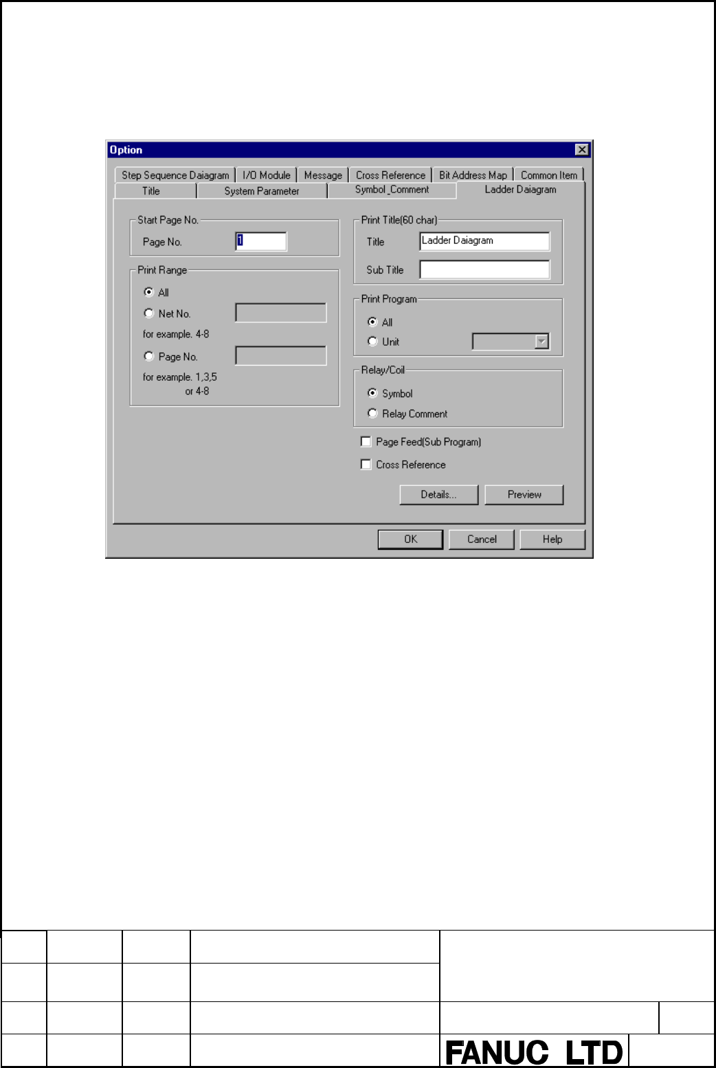
5.3.8.5 Ladder Diagram print
Set the option of the Ladder Diagram print.
(1) Ladder Diagram print option screen
Fig. 5.3.8.5(a) Ladder Diagram print option screen
Details of each item are as follows.
[Start Page No.] Group Set page number.
[Page No.] Set beginning page numbers of the Ladder Diagram to be
printed. An integer value can be set. In default, “1” is set.
[Print Title] Group Specify the title and the sub title printed when the frame
print is specified. A title and a sub title can be specified
up to 60 characters.
[Title] Specify the title of the Ladder Diagram print. In default,
“Ladder Diagram” is set.
[Sub Title] Specify the title printed with the Ladder Diagram. Any
character string is not set in default.
[Print Range] Group Set the range of the print. In default, [All] is checked.
[All] All are printed.
[Net No.] Specify the range of the net, which you want to print.
[Page No.] Specify the range of the page, which you want to print.
Contents Summary of FAPT Ladder-II Operators manual
- Page 1GE Fanuc Automation Computer Numerical Control Products FAPT LADDER - II Operators Manual B- 66184EN/02 April 1998
- Page 2Warnings and notices for GFLE-003 this publication Warning In this manual we have tried as much as possible to describe all the various matters. However, we cannot describe all the matters which must not be done, or which cannot be done, because there are so many possibilities. Therefore, matters wh
- Page 3[Notice] 1. The FAPT LADDER-II software is copyrighted by FANUC Ltd. 2. No part of the software or this manual may be used or reproduced in any form without the prior consent of FANUC Ltd. 3. The software shall be installed on no more than one computer at a time. Separate software packages must be p
- Page 4CONTENTS 1. GENERAL . . . . . . . . . . . . . . . . . . . . . . . . . . . . . . . . . . . . . . . . . . . . . . 1.1 OVERVIEW . . . . . . . . . . . .. . . . . . . . 1.2 THE MAJOR FUNCTIONS . . . . . . . . .. . . . 1.2.1 The Overview of PMC Function . . . . . . . 1.2.2 PMC Models to be Supported . . .
- Page 54.53 Printout ................................................ 101 453.1 Overview ........................................... 101 4.5.3.2 Starting and ending printing .............................. 102 4.5.3.3 Output item setting .................................... 103 4.5.3.4 Print format-l: SETUP
- Page 64.6.2.2 Parameter screen for on-line monitor .................. . 193 4.6.2.3 Modifying parameters ............................. . 194 4.6.2.4 Starting and stopping the on-line monitor function ......... . . 194 4.6.2.5 Starting and stopping the on-line monitor function (Only for Power Mate-H) .....
- Page 7
- Page 8I. BASICS (NORMAL OPERATIONS) . ,,,,,, ,,, ,, ,,, ,,,
- Page 91. GENERAL 1. GENERAL 1.1 Overview Thank you for purchasing FANUC FAPT LADDER-II. FAPT LADDER-II is a programming system for developing FANUC PMC sequence programs. This software is designed to operate on IBM PC/AT and compatible computers running MS-DOS, and supports both the Japanese and English l
- Page 101. GENERAL The following abbreviations are used in this manual. 1) For PMC models Abbreviations PMC Models PMC-R Series . PMCRA3 FANUC PMC-MODEL RA3 . PMCRB3 FANUC PMC-MODEL FIB3 PMCRB4 FANUC PMC-MODEL RB4 PMCRB5 FANUC PMC-MODEL RB5 PMC-RB6 FANUC PMC-MODEL RB6 PMCRC3 FANUC PMC-MODEL RC3 . PMCRC4 FAN
- Page 111. GENERAL 1.2 The Major Functions 1.2.1 The overview of PMC function L . . . . .. .. .. . . .. . . .. .. . . ...) CNC (.......... i Machine Tool RS-232-C PMC DVDO RS-232-C ” .,.,,.. . ... (INLINE functions through RS-232-C (Note 1) Monitorring & debugging a sequence program j Run/Stop a sequence pr
- Page 121. GENERAL < Functions of FAPT LADDER-II > Input, Output, Display and Edit sequence program Monitoring and Debugging of sequence program (Display of signal status, PMC alarm, PMC status.) (Online monitoring of ladder diagram. Display of cross reference.) Setting and display PMC parameters . Run/Stop
- Page 131. GENERAL 1.2.3 The procedure to make a sequence program Start of control system development + Decrde the control object (machines, CNC) t Decide the specifications of control operations Calculate the number of DVOO points Estrmate the control scale Create the ladder diagram (desrgnicreate addoress
- Page 141. GENERAL 1.3 About PMC Program 1.3.1 PMC programming method The ladder method is most of ten used for programming the sequence control governed by a PMC. This method was derived from relay-panel control circuits. Since it has been in use for years, many sequence engineers are already fatiiiiar wit
- Page 151. GENERAL The configuration of a sequence program A sequence program consists of the following 5 kinds of program unit ; . The 1st level of ladder The 2nd level of ladder The 3rd level of ladder Subprograms of ladder Subprograms of step sequence LEVEL 1 ( LADDER) LEVEL 2 ( LADDER) LEVEL 3 ( LADDER)
- Page 161. GENERAL (3) Data flow - FAPT LADDER-II I Source program Ladder 1st level Mnemonic Mnemonic program A mnemonic program without step sequence t Compilation/Decompilation 1 Object code IMemory I card format file I ‘------I! t Input/Output Input/Output I I I RS-232-C Handy File Memory card FLOPPY CAS
- Page 171. GENERAL 1.3.2 About symbol & comment data On FAPT LADDER-II, you can assign names or add notes to l/O signals, internal relays, and can add notes to a sequence program. They are generally called”symbol & comment data”. (1) The definition of terms The definition of terms are shown below to disting
- Page 181. GENERAL (b) For ladder sequence program Specification Net comment Available characters ASCII characters Japanese kana/kanji characters Line feed Steps to occupy 2 step/Net comment Maximum characters/line 64 characters/line 4095 characters/Net comment (Note 1) Maximum lines 100 lines/Net commennt
- Page 192. OPERATING ENVIRONMENT 2. OPERATING ENVIRONMENT To use this software, the requirements indicated in the table below must be satisfied. Computer IBM PC/AT and compatible machines (Note 1) ICPU 386 or hrgher OS MS-DOS Version 5.OAlior later (to activate Japanese system) I-- Memory IHard disk MS-DOS
- Page 202. OPERATING ENVIRONMENT (2) EMS and XMS memory for Symbol & Comment data FAPT LADDER uses EMS and/or XMS memory lor Symbol & Comment data if available. When neither of them are available, FAPT LADDER will make temporary file on the hard diskdrive, and processing large number of Symbol & Comment dat
- Page 213. THE CONTENTS OF PACAGE AND INSTALLATION 3. THE CONTENTS OF PACAGE AND INSTALLATION 3.1 The Contents of Pacage FAPT LADDER-II is stored in 5 floppy disks listed below. The media size is 3.5 inch 2HD (1.44MB). Please confirm contens. (1) FAPT LADDER-II (Vol. 1)‘A08B-9201 -J503#ZZO7-1 (2) FAPT LADDE
- Page 223. THE CONTENTS OF PACAGE AND INSTALLATION @ If installation completes, the message below appears. (Note 1) To stop installation, press the
key. (Note 2) Note that the files in the directory specified to be installed are all deleted 3.3 Directory Configuration After Installation The installer - Page 233. THE CONTENTS OF PACAGE AND INSTALLATION . ‘.INF (b)Communications (For details. see Section 4.5.6.1.) . FL10 - AT.DAT (c)Compile/decompile (For details. see Section 4.573.) OPTION.CNF (d)Entire system FLMNE.DAT (For details, see Section 4.5.8.7.) FLVIEW.DAT (For details, see Section 4.5.9.) (2) O
- Page 243. THE CONTENTS OF PACAGE AND INSTALLATION (c)Message conversion tools (For details. see Appendix 5.) - CHGMES.EXE 3.4.2 The constitution of source program In FAPT LADDER-II, a sequence program, which is object of editing and printing, is called “source program” and managed by storing in files below
- Page 254. OPERATION 4. OPERATION 4.1 Activation (1) Activation method 01 Move to the drive and directory where the FAPT LADDER-II system software is installed. 0 Key in “FLADDER -z Enter > ” (Example) Start FAPT LADDER-II when the software is installed under the \FLADDER directorv on drive C: 1~:=~f%?f!)~E
- Page 26
- Page 274. OPERATION (2) There are two methods of returning from the FAPT LADDER-II initial menu screen to the DOS command line. Press the < Esc > key while the initial menu screen is displayed. Alternatively,select menu item “END” from the initial menu. For details of selecting a menu item from the initial
- Page 284. OPERATION 4.2 GENERAL OF OPERATIONS 4.2.1 Menu Configuration The configuration of the menu screens displayed by the system are shown below. $ - Program Selection TOP screen Off-Line Function - (1) (See Fig. 4.2.1 (b)) -I+ - - On-Line Function - (2) (See Fig. 4.2.1 (c)) - On-Line - (3) (See Fig. 4
- Page 294. OPERATION File save Off-Line Function Exit (3) On-Line Function Diagnose Ladder Monitor/ Timer (selected program) Online Editor Counter 1 t - PMC Status Keep relay - Signal Status Data table control - PMC Parameter Data table - PMC alarm status - RUN/STOP the ladder - System Information -21-
- Page 304. OPERATION 4.3 Common System Operations The operations described below are common operations for FAPT LADDER-II. (1) Function keys When the menu items shown below are displayed in reverse video, the user can select the desired menu item by pressing the corresponding function key. I1 IF11 WI IF31 I
- Page 314. OPERATION (7) Status line A status line is displayed at the top of the screen. Main menu PMC-RB3
[c: \FLADDER 1 t- Item name t Model currently selected t- Current currently selected directory name Edit mode (overwrite/insert) (Note) The indications on the key tops may slightly vary from the de - Page 324. OPERATION (9) Pull-down menus On some screens, the following menu bar is displayed along the top of the screen: ....; FiM’; ::: ,.‘:.‘, 2. Diagnose 3. l/O 4. Communication %I& I I I I I J 1 I I I Function number. ) Function name Icon for PMC status indication (See the section explaining how to st
- Page 334. OPERATION 4.4 Initial Menu The inttial menu screen appears when the FAPT LADDER-II system is started. See also Section 4.1. This screen reappears upon the termmation of a function chosen from this menu. To select a function from this menu, use the
key to move the cursor down to the desired - Page 344. OPERATION PMC E;IB I’MC -NBZ SPliTI PMC type for new program. Fig. 4.4.1 Selection of PMC type 4.4.2 Off-line function When “OFF-LINE FUNCTION” is selected from the initial menu, the off-line menu screen appears (Fig. 4.4.2). The off-line function includes a function equivalent to the FAPT LADDER
- Page 354. OPERATION 4.4.3 On-line function When “ON-LINE FUNCTION” is selected from the initial menu, the on-line function is applied to the programs held by the PMC. Programs are loaded into the personal computer by means of automatic communication with the PMC. For details, see Section 4.6. 4.4.4 On-line
- Page 364. OPERATION 4.5 Off-line function 4.5.1 F2 KEY PRINT F3 KEY COHPILt F1 KEY OFCOHPILF F5 KEY I/O Ff, KEY PROGRRH OPTION SET-UP FI KEY MNEMONIC EDIT t8 KtV UllLllV tY KtV ON-LLNt CUNCIION Fig. 4.5.1 Off-line Menu Screen 4.5.2 Editing The source file of a sequence program is edited. (1) Start [Operati
- Page 374. OPERATION 8 The followlng editing menu screen appears: Fig. 4.5.2 (b) Editing Menu 0 Select data to be edited with the corresponding function key. 69 The editing screen for the selected data appears. For example, the screen below is displayed when [TITLE] is selected. EDIT ( TlTUi ) m*<. : y:,:.
- Page 384. OPERATION (2) Termination [Operation] cis Select [END] or press the e ESC > key on the editing screen. 02 The following message appears: E-1 Save (update) & quit F2 Quit F3 Edit CC Press the desired function key. (0 When UPDATE is selected. the editing operation is terminated after the results of
- Page 394. OPERATION G9 The following title edrting screen appears: I) KKIIINI:TWI. Blllll)tiR NA’k’ 2) WIIIM; 11XJI. NM 3) fm: & NCNM : FINK I’M:HltlEl.K & I:IfM I) PMC PRICRAM NO 8) I’RWAMW:SIGNRI) BY !I) RtMMIII’KN HY Fig. 4.5.2.1 (2) Input [Operation] (I) Select an input ttem (displayed in reverse video
- Page 404. OPERATION (3) Termination [Operation ) 01 Select [END] on press the -z ESC > key to return lo the editing menu screen. B, The following message appears. 11 0 Press the desired function key. The system returns to the editing menu. 4.5.2.2 Ladder diagram/step sequence editing (1) A program configur
- Page 414. OPERATION (a) Screen display (Pxxx represents a subprogram number) Screen display Meaning Display by [ZOOM] or < Enter > 0 LEVEL1 the 1stladder level ladder diagram j--J LEVEL2 the 2nd ladder level ladder diagram 0 LEVEL3 the 3rd ladder level (Note 1) ladder diagram 0 Pxxx a subprogram ladder dia
- Page 424. OPERATION (b) Creating a new subprogram - Press the [NEW] key. New program name ?D 1 - Enter the number of the subprogram to be created (P200, for example). (c) Modifying a subprogram - Key in the number of the subprogram to be modified (P200, for example), then press the [ZOOM] or
key. A - Page 434. OPERATION (2) Editing a ladder diagram (4 Start Display the program list screen. Position the cursor lo the program indicated by 0, then press the [ZOOM] or
key. The ladder diagram editing screen, shown below, appears. ItlD-XQ 8 CCO=lESI DATR NO 1 800Bl‘/kWOl‘ ‘SY=S!JNPLE 00001 RCO=RELRY - Page 444. OPERATION C-9Function key indications and selection The ladder diagram editing functions correspond to the function keys as indicated below. 0) (cornand] 8 J 63 [comand] (3) Under condition 0, holding down [SHIFT] lets you select the following items. (a Under condition 8. holding down [SHIFT] let
- Page 454. OPERATION (Note) Whrle the functron keys of ti) are displayed in ladder diagram editing, a command of 0 can be executed. For example, entering and (COMAND] on the 0) screen has the same effect as selecting F4 [Adress] on the @I screen. To select a command of 0 in this way, enter the upper-cas
- Page 464. OPERATION Enter address Y52.7, then press the < Enter > key. The cursor automatically moves to the input start position on the next line. Next, enter an OR conditron. Press [ -#+- J and enter address X2.4, then press the -Z Enter > key. The address is set at contact B and the cursor moves right.
- Page 474. OPERATION [Operation 1 0 Enter a control condition. Press [ ---I l--- 1. Next. enter an address and bit data, then press the < Enter> key. The cursor moves right.. Q Enter a function instruction. Press the (functnj key. Next, enter SUB number 8. then press the
key. The function Instructto - Page 484. OPERATION total for that screen. In addition, a space line between nets is counted as a valid line. The number of lines tn each net to be displayed is determined as follows: (b-l ) Basic instructions One line is comprised of one basic instruction. +_I- 1 line 1-r *lines (b-2) Function instruction
- Page 494. OPERATION (b-3) Data table section of function instructions The data table section of the COD, CODB, or DISP instruction is calculated as follows: - When the data table is one or two bytes Number of lines = number of data tables/6 ( + 1 if there is a remainder) ACT --i+ SUB 49 0011 DISP 0003 0300
- Page 504. OPERATION (b-4) Example of calculating the number of lines per screen For the ladder shown below, the number of lines in the screen display section is obtained as follows: - The valid nets on the display screen are nets A and 6. - Number of lines in net A Function instruction section + data table
- Page 514. OPERATION Example of symptom (a-2) - If an attempt is made to enter the net of a function instruction on the same screen as that of a basic instruction, the following message is displayed, and the attempt is rejected. “The NET being created is too large.” For example, if the basic instruction net
- Page 524. OPERATION attempt is rejected. “The NET being created is too large.” This symptom also occurs In a combination of two DISP instructions and a combination of CODB and COD instructions. For example, if the number of tables for the CODB instruction is 200, the total number of steps for the DISP inst
- Page 534. OPERATION [Notes] 0) An attempt IO scroll a program on the screen with a scroll key or other keys fails if the ladder program is incomplete (for example, without addresses) or invalid. A correct ladder program must be created before the screen can be scrolled. 8 Up to eight contacts and one coil
- Page 544. OPERATION l When a vertical line affects addition [Operation] Move the cursor to the position shown above. Press [ 4_ ] to delete the vertical line to the left extending upward. This disappears. Press [ J ] to create a vertical line extending upward to the right of the cursor, then press [ - 1. A
- Page 554. OPERATION When the [insnet) key IS pressed without entering a numeric value, one line is Inserted. When the [rnsnet] key IS pressed after entering a numeric value, the number of lines specified is inserted. Move the cursor to the desired position and press [ -_1 f--j. Then set address data and pr
- Page 564. OPERATION II the (inselm] key is pressed when the cursor is placed as shown in the left-hand figure, an element is inserted as shown in the following figure. The element is inserted before the cursor. If the character is entered and the [inselm] key is pressed when the cursor is placed as sh
- Page 574. OPERATION 0 Execution : Press the [exec] key. Cancellation : Press the [cancel] key. Deletion except : Press the [exclud] key. Exclude nets except specified nets in 8. specified nets r4, When the nets to be deleted are known beforehand, move the cursor to the first net to delete, enter the number
- Page 584. OPERATION x2.0 F54.1 Y52.3 G11.6 I” -;+@ri@#%?. Cl 035.3 .( I, - When the same address as this address II is to be searched for, move the cursor to G17.2 X4.2 Y49.1 this position, then press the [srch] key. x14.0 032.0 +I F54.1 b G43.1 - When the same address is found, the cursor moves to this lo
- Page 594. OPERATION When a relay coil with the specified address is found, the section of the program containing it is displayed on the screen and the cursor is positioned at the relay coil. If the search operation fails to find a relay coil with the specified address, an error Indication appears. (v) [n-s
- Page 604. OPERATION G-SRCH mode continues unless pushing the c ESC > key or the [cancel] key. 1st net of LEVEL1 Whole program - Final net of the maximum numbered subprogram -1 (Searching in the order of 0 -@) . l Searching result When the object of search is found, the cursor will move to the position. In
- Page 614. OPERATION l Operation The global search is operated with the following functton key. ,,;‘~+.$-s+~ 4-4 5 -t&&t* 6 -..-L-,~‘L~_“a t@r .+_ s +r. j ,o&~er) (cornand] J 8 [comand] i insnet 2 D&net 3 in5Qtt 4 AdrQSj, 5 %arctI 6 Copy 7 &lrruc 8 Fk 9 iyhdlt lo d) Select the (G-srch] with pushing the [SHI
- Page 624. OPERATION File which is being edited Specified file (COPY 1 Range to be copied [until] Fig. 4.5.2.2 (b) I to cancel sear& c-down Pup &fil tu-arg [Operation] Copying a net Place the cursor on the net to be copied and press the [Copy] key. The selected net is displayed in yellow. Copying two or mor
- Page 634. OPERATION cursor. To copy the selected net or nets two or more times, enter the number of times they are to be copied before pressing the [to] key. Specifying the copy destination using the (to-fill key (Copying the net or nets into another file) 1) Press the (to-fill key. The following message i
- Page 644. OPERATION [Operation] Substituting [Move] for [Copy], follow steps 0 to Q for copying. (Note) Incorrect nets cannot be moved. (i) Combining a sequence program A source program can be combined to another source program that is being edited. The source program to be combined can be displayed and ed
- Page 654. OPERATION (i) Function keys [Comand] I itwhet Delnet Insert A&en Mitch COPY Mbw? ; ‘Flli .’ ::... i@llt r d SIIWPLE YO 0 -+ t------- __-_ - ---_c+- I I I ~334~5ulumm3rn331~’ rRD= 1SY= cco- wao1 RCO= -___ _ Fig. 4.5.2.2.2 (d) Screen Displayed when a File is Opened by the [File] Command - 57 -
- Page 664. OPERATION (ii) Operation flowchart for combining a sequence program Start ladder diagram editing (original screen) 1 Specify an Insertion point (The data is inserted Immediately above the cursor.) 1 Press the [File] key r_lrC1T7 Specify
- Page 674. OPERATION (iii) Examples Example 1. Combrning a sequence program file [Operation] Place the cursor on the insertion point on the original screen. Select [File]. Enter the name of the file to be combined and press the -z Enter > key. From the following menu, select Fl (To). /I The file is inserted
- Page 684. OPERATION From the following menu, select Fl (Save). Fl Save (update) F2 Quit F3 Rename & Save F4 Edit F5 Create Latemp file Return to the screen of step @ and check the name of the file output in step ‘$3. Then, select Fl (To). The file is inserted immediately above the net specified in step 0.
- Page 694. OPERATION (k) Editing a symbol and comment from the ladder diagram editing screen On the ladder diagram editing screen, a symbol and comment added at the specified address can be edited. [syEdit] [Operation] Specifying an address To edit a symbol and comment in a ladder diagram, place the cursor
- Page 704. OPERATION (m) ZOOM Subprograms called by the currently selected program’s issuing of a CALLCALLU instruction can easily be referenced and edited. (i) Start up of zoom 0 Moved the cursor to the parameter of the CALLCALLU instruction and push the
key. ROOl .O ACT IL - SUB65 PO01 CALL @ The - Page 71
- Page 724. OPERATION @ Lines at the cursor and after are shifted down, and the area for comment enclosed by ‘(*’ and “)’ is inserted. Then the cursor changes into character-size cursor, and type comment sentence onto the area. The area for Net comment expands and shrinks by two lines (four lines at four lin
- Page 734. OPERATION [inslin] will shrfl irnes at the cursor and after down by one line, and make a blank line at the cursor position. (’ Net comment is written in here. ‘) (’ ‘) (’ All characters you can enter are available. l) (’ *) (3 At Net comment editing mode, to delete by line, press [dellin]. (* Net
- Page 744. OPERATION (p) To edit New page It is able to specify the position to feed page at printing ladder diagram. This specification of the position is called “New page”, and each of them occupies two steps in sequence program. 0) To enter New page 0 Move the cursor to the position you want to feed page
- Page 754. OPERATION The following editing end menu(pop-up menu) appears. a) Fl :Save(update) & quit After current content of the editing is preserved, the editing screen will be ended. b) F2:Quit Alter current content of the editing is cancelled. the editing screen will be ended. c) FB:Rename,save & quit A
- Page 764. OPERATION (3) Step sequence diagram Position the cursor to a program marked with 01, then press the [ZOOM] or < Enter > key. The step sequence editing screen is displayed as shown below: ZDIT(LADDER/STEP SEQUENCE) R~~(~TEP SEQ) [A:YFLYDATAYSFCO~] PROGRAM:(STEP SEQUENCE DEMO PROGRAM) Cl s3 0 Sll c
- Page 774. OPERATION When the cursor is on the transition line, following softkey menu is displayed. P30 t 1== 1 f-.- (f-1 FUNC CHK ZOOM I t 1 : Transition I l- I : Divergence of selective sequence 1 l= = 1 : Divergence of simultaneous sequence I I I : Line for link I t- 1 : Convergence of selective sequenc
- Page 784. OPERATION STEP : 61 ACTION : PlO l-l To change the step number, press the
key to position the character cursor ” ” on STEP and use the [BS] key to change the number. STEP : Sl(f ACTION : PlO l-l (ii) Entering a transition Position the cursor to the desired input position, then press the - Page 79
- Page 80
- Page 814. OPERATION (vii) Specifying a label for jump destination Position the cursor to the desired input position (step line), then press the [c LBL] key. Then, enter a label name. Press the I+- LBL] key. Ii- WI Sk PI0 I- PlOO LABEL : Llo l-l II [l.ll I II I + JMP + LBL -L FUNC CHK ZOOM Enter a label nam
- Page 824. OPERATION (viii) Specifying a label jump Position the cursor to the dewed input position (step line), then press the [- JMPJ key. Then, enter a label name. Press the [- JMP] key. t LlO [OISl to I Ells2 f PlOO .- LEBEL : 2-3 0 [Ul 01 I --*JMP +-LBL -L FUNC CHK ZOOM Enter a label name. 1 + LlO [UlS
- Page 834. OPERATION Deleting an element Position the cursor to the element to be deleted. then press the < Delete > key. In the example shown above. two figures (elements) of a selective branch and transition are selected Specify the element to be deleted with the narrow cursor, displayed in reverse video.
- Page 844. OPERATION To specify another figure, press the < Delete > key again. I IO1 Sl PlQO i Inserting an element Position the cursor to the desired insertion position, then press the c Insert > key. To create an empty row, press the
key. To create an empty column, press the [Shift] and - Page 854. OPERATION Press the < Insert > key. c PI 1-3 Press the (Shift] and < Insert > key. I c 101 Sl Pl ============ I I I rllS2 n SlO i-l s20 P2 PlO P20 t t t Ll s3 r3 Sll Ll s21 I I I STEP : s2 ACTION : P102 l-3 - 77 -
- Page 864. OPERATION (xi) Search Pl ~,=y== i ==== ; = ols2 El SlO cl s20 Pl Pll P21 ;. 1 t u SlO 0 s20 ciilS2 I I If the [F8] (FUNC) key is pressed in the stale shown above, a pop-up menu is displayed as shown below: l-7 Fl Search F2 COPY F3 Move F4 mAin F5 List I I Ells3 El Sll 0 s21 Press the (Fl] (Search
- Page 874. OPERATION Then, press the [Fl] (Step) key. Another pop-up menu is displayed, as shown below: t Pl .xb La search string:%Ai I SI Position Toe Bottom Enter the step number to be searched for (S20, for example), then press the
key. The system starts searching through the part subsequent to t - Page 884. OPERATION When the [FBI (FUNC) key is pressed, a pop-up menu is displayed as shown below: Pl t PI========= Fl Search F2 Copy F3 Move F4 mAin F5 List : Press the (F2) (Copy) key. The system prompts the operator to enter a start point. Pl t =========PI I I L71s2 cl SlO Ll s20 Pl Pll P21 i......+ 1
- Page 894. OPERATION Position the cursor to the desired end point (position 3-4 in the example shown below), then press the < Enter > key. The system prompts the operator to specify a copy destination. Pl t ===PIIP===I ACTION : SpeciEy End position 3-4 Position the cursor to the desired copy destination (po
- Page 904. OPERATION (xiir) Returning from the ZOOM destination to the program configuration screen (MAIN). To return to the program configuration screen, displayed when editing was started, follow the procedure below. The system assumes that the editing of the step sequence subprogram, from which the [ZOOM
- Page 91
- Page 924. OPERATION Following keys are useful in this screen. Function key Other keys [ MAIN ] :Displaying the subprogram < Page up > : Displaying previous screen configuration screen < Page down > : Displaying next screen [ CHANGE ] :Creating a new subprogram (ZOOM J :Modifying a subprogram Screen display
- Page 93
- Page 944. OPERATION When the [ZOOM] key is pressed, the figure pointed by cursor decides the type of subprogram which is to be edited. Figure Meaning of the figure Subprogram to be edited cl Step sequence subprogram Ladder subprogram 01 Initial step sequence subprogram Ladder subprogram n1 block step seque
- Page 954. OPERATION 4.5.2.3 Symbol & comment editing l Moving the cursor < t >, < + >, CT >. < 1 > Moves the cursor to another field to be edited.
+ ,<-+> Moves the cursor to another position within the field to be edited. l Entering a comment in Japanese When a front-end processor for Japanese - Page 964. OPERATION (2) Entering a new symbol and comment A new symbol and comment can be added at an address to which no symbol or comment is assigned. [Operation] m Select [ADD] on the symbol and comment editing screen. 8 An input window opens on the screen. t t t t Address field Symbol field Relay COmme
- Page 974. OPERATION (4) Moving a comment A comment assigned to an address can be moved to another address. [Operation] 0 Place the cursor on the comment to be moved. 8 Select [DELETE]. 0 The following message appears on the screen. Comment data copied to paste buffer @ Place the cursor at the place the com
- Page 984. OPERATION 6% The system searches for the symbol or address and the data number in that order. The cursor is moved to the searched data. (7) Deleting a symbol and/or comment (a) Deleting both a symbol and a comment [Operation] 0 Place the cursor on the NO field. 8 Select [DELETE]. Both the symbol
- Page 994. OPERATION (9) Editing screen +Symbol entry number --) Coil comment size (byte) CRT/MD1 can display / Total CRT/MD1 can display / Total I EDIT ( SYMBOL b COMMENT ) PMC-RB4
[A:vFLYDATAYRB4 I +YYMBOL 000001/000003 COIL_COMMENT 0000030/00000090 NO. ADDRESS SYMBOL RELAY COMMENT COIL COMMENT F (Mote - Page 1004. OPERATION 4.5.2.4 Message editing An arbitrary message can be displayed on the CRT/MD1 screen of the CNC, using the DISPB instruction (SUB 41), which is one of the function instructions. Such a message is created as described below. (1) Types and quantity of characters that can be used The types
- Page 1014. OPERATION 8 The following message data edit screen appears. EDIT W&AGE) _~ IO ADDRESS NSSAGE ___- 001 AOO.0 1234567890ABCOEFCHIJUMOPWSTllWYZ1234567890AlKDEFGHIJKlM~ST UVWXYZ1234567890AKDEFGHIJKUR(DFQRSTUYWXYZ 002 AOO. I 003 A00.2 004 A00.3 Fig. 452.4 (a) Message Data Edit Screen (b) Input [Operat
- Page 1024. OPERATION (e) END [Operation) 0 On the edit screen, press [END] or < ESC >. 8 The following message appears. 0 Select one of the above items, and return to the edit menu. 452.5 I/O module editing The address of each module in the I/O unit IS set and deleted as described below. (1) Startup [Operat
- Page 1034. OPERATION EDIT II/O MDDULE) \B& ICHANNEL 11 1 ADDRESS GROUP BASE SLOT NAUE ADDRESS GROUP BASE SLOT NAUE I xoooo 0 Do PX YOoilO xoool i 00 ux YOoill x0002 0 i ux YOoO2 x0003 0 0 ii x(1 YGilO3 x0004 YooO4 x0005 0 0 01 XI Yooo5 X0006 YOOo6 x0007 YOoO7 XGQOE YOOo6 xOiw9 YOO09 x0010 YOOIO XOOII YOOll
- Page 104
- Page 105
- Page 106
- Page 1074. OPERATION [Input item] COUNTER DATA TYPE This parameter specifies whether the format of a counter value used with the CTR function instruction is to be binary or BCD. lnitral value 0 : BINARY Setting 0 : BINARY / 1 : BCD LADDER EXEC (ladder execution time) This parameter specifies an incremental
- Page 1084. OPERATION LANGUAGE ORIGIN This parameter specifies the start address of the link control statement data of a language program. I Initial value 000000 I Setting range Address area in the language program storage I When there is no language program, specify OOOOOOH. OPERATOR PANEL (connectinq an FO
- Page 1094. OPERATION 4.5.3 Printout 4.5.3.1 Overview A sequence program can be printed out. (1) Compatible printers This software is usable with the printers listed below. EPSON VP1 000 (default setting) NEC PR201H FANUC PRINTER (Note) To use a NEC PR201H and FANUC PRINTER, a program modilication is require
- Page 1104. OPERATION 453.2 Starting and ending printing Printing is performed according to the following procedure. SYSIEM PRRAWETER SYMBOL 8 COMWFNI LROOER OIRGRRH [OPTION1 STEP SEOUENCE OIRGRRH INOm1 IOPTIONI I/O HOOULt HESSRGE '"PTIONI CROSS REFERENCF LIST 8% BII ROORESS MRP 'ml1 rurlION1 Fig. 4.5.3.2 Dr
- Page 1114. OPERATION 453.3 Output item setting Items to be output to a drawing are specified as described below. More than one item can be specified at a time. Some set items may not be displayed, depending on the model of the PMC. (1) Specifying output of each data item Specify whether a data item is to be
- Page 1124. OPERATION i) Option (symbol printing) . When printing symbol/comment data, specify an output range. When 0 is specified as the print end line number, all data up to the last line is printed. . Comment specification [RELAY] : Prints relay comment data. [COIL] : Prints coil comment data. [ALL] : Pr
- Page 1134. OPERATION e) Printing of step sequence figure Step sequence figure is printed i) Option (Step sequence figure printing) :\DtllA\SRWPLE I I STEP SEDUENCE PAINT 1 PRINT UNIT oRLLn5m5l MODULE NM SUE-PRDGRRM NUMBER r~/vEsl FlB t tsc I END ,-a3333momm -__- Fig. 4.5.3.3 (c) Step Sequence Print Option M
- Page 1144. OPERATION i) Option (message printing) The range of messages to be printed is specified. h) Cross-reference list printing A cross-reference list is printed r Fig. 4.5.3.3 (e) Cross Reference List Print Option Menu i) Option CHECK DUPLICATE WRITE Check multiple writing to a coil and multiple use o
- Page 1154. OPERATION APPOINT COMMENT Specify the kind of comment data ‘RELAY’ Print Relay comment. ‘COIL’ Print Coil comment. ii) Bit address map The bit address map is printed. .\DAlA\SRMPLE I BIT ADDRESS MAP PRINT I OUTPUT RDDRESS RPPDINT RDDRESS FIB I FSC FND Fig. 4.5.3.3 (f) Bit Address Map Print Option
- Page 116
- Page 1174. OPERATION (1) Printout example by “F2[SETUP]” (print menu)
4 Initial step I’ Sl f Initial step Pl : Pl PlOO 4 Transition + PlOO 4 Transition + ( c-L1 Label c-L1 Label 0 s210 * s210 : PlOl f- Divergence of selective e Divergence of selective P160 s - Page 1184. OPERATION (3) Printout example of more than one page. Size of one page I q r-l-l ttd Cl Cl cl tttll 22 element El cl cl cl cl (28 element) tttt Cl cl cl cl 0 cl 14 element ’ 0 Note) The maximun element count for printing without sub-program number is given in t parentheses. (l/3) I q r- Link numb
- Page 1194. OPERATION 4.5.3.4 Print format-l: SETUP menu Specify printer forms and a print format as described below. PtlPER SIZE / LADDER PRINT 15 INCH/ RSCII 15 INCH/ GRRPHIC Fig. 4.5.3.4 SETUP Menu Screen [Operation ] 0 Select F2 [SETUP] from the output item selection screen. @I The SETUP menu screen appe
- Page 1204. OPERATION 4.5.3.5 Print format-2 (AMOFTRP, DAT/* .INF/message file) Each parameter file of this software can be rewritten using a commercially available text editor -- 5” that the output format shown in each of the following frames can be changed. -AMROFTRP. DAT -PR201-10 . INF [Diagram output ]b
- Page 1214. OPERATION (1) Changing the paper selection name This item makes it possible to change the name of each choice during diagram output format selection. Name of file to be Point of change Settings edited AMROFTRP.DAT #l O-A = 1O-inch/ASCII Arbitrary character string consisting of #l O-G = 1O-inch/gr
- Page 1224. OPERATION File edited Modifications Settings AMROFTRP.DAT LCNTL = 4 Specify either 4 or 5 (Set for each sheet) , (4) Setting the printer model and print paper This item can change the printer model and print paper that are specified during paper selection. Name of file Point of *.INF that can be
- Page 1234. OPERATION (5) Setting the line spacing This item can specify the line spacing of a diagram when it is output. The file to be edited is the one specified according to the descriptions in Section 1.4.4. Name of file to be Point of change Settings edited ‘.INF LPI (H) (1B) (C) (T20) ; (H) (18) (C) (
- Page 1244. OPERATION (7) Setting the title of printout This item can change the title of a diagram when it is output. Vame of file to be Point of change Settings edited .PRTOUT. JPN. @ SYSTITLE (C) (
- Page 1254. OPERATION (9) Setting the cross-reference list output information This item can specify step and/or net numbers to be output as cross-reference information. If both step and net numbers are specified, which is to be printed first can also be specified. In the CROSSINF.DAT file, lines with no semi
- Page 1264. OPERATION (11) Setting the cross-reference list read/write coil guidance informatlon This item can set a comment about coil attributes. In the CROSSINF.DAT file, lines with no semicolon at the beginning are valid. Name of file to be Point of change Settings edited CROSSINF.DAT READ = Character st
- Page 1274. OPERATION Environment settings for diagram printout - example 1 (settings in file AMROFTRP.DAT) Changing the types of #PAPER = 10-G printout paper #PAPER = 10-G I #IO-A = 10 inch/ASCII * #lo-A=NEC 10 LENGTHL = 11 The name is changed from LENGTHL = 11 LENGTH = 11 1:lO inch’ to ‘l:NEC 10’. LENGTH =
- Page 1284. OPERATION Environment settings for diagram printout - example 2 (settings in file PR201_10.INF) . PRZOlH3 CNTINF ( CRLF FORMF CPI CANCEL LDRCPI * LPI (H)(W(C)(T20); * LDRLPI (H)(W(C)(T15); * LMARGIN (H)(W(C)(LOOO); RMARGIN (H)(W(C)(/O7W LDRCHAR (H)(W(C) (50014); JPNSET (H)(W(C)(K); JPNRESET (H)(W
- Page 1294. OPERATION Environment settings for diagram output - example 3 (sample setting 1 of the CROSSINF.DAT file) l Sample setting of the CROSSINF.DAT file : GUIDE=STEP No./NET No. NET-INF=2 STEP-INF=l FROM=S%s/N%s READ=-1 I- -I/I- : WRITE=-()- -(/I- : NL=l FF=O ; 0 Sample cross reference output [A:\FLAD
- Page 1304. OPERATION Environment settings for diagram output - example 4 (sample setting 2 of the CROSSINF.DAT file) l Sample setting of the CROSSINF.DAT file : GUIDE=Step number NET-INF=O STEP-INF=l FROM=S%s READ=read WRITEwrite NL=O FF=O ; 0 Sample cross reference output (A:\FLADDER\SAMPLE] *** Cross refe
- Page 1314. OPERATION 4.5.3.6 Changing the printer specification Upon the completion of installation, the default printer is set to EPSON VPlOOO. (1) Changing the printer specification lo NEC PR201 To enable output to an NEC PR201 printer, change the setting file by means of the procedure described below. (I
- Page 1324. OPERATION 4.5.4 Compilation During compilatron, an edited source program is translated into an object file executable by the PMC. Uncompiled programs cannot be transferred to the ROM writers (PMC writer or FA writer) or RAM for the PMC. Compilation can be performed in one of two modes: normal mod
- Page 1334. OPERATION On the other hand, condensed mode has the restrictions described below.
- Page 1344. OPERATION l General Flow of Operation for compiling I Offline menu I I Offline menu I Fig. 4.5.4.1 (b) Compiling General Operation and Screens (2) Compile (a) Normal mode With PMCPA3, compile processing is always performed in condense mode. [Operation] 6 Select Fl [EXEC]. 0 Compile processing is
- Page 1354. OPERATION If many errors have occurred, those errors can be easily identified by viewing the relevant file wtth the text editor or by printing out the file. The results of execution can also be displayed using a utility function. (See Section 4.5.9.) Example: When the program shown below is compi
- Page 1364. OPERATION 4.5.4.2 Compile options These options’ initial value can be changed at the Program option set-up. (Refer to 4.5.7 Program option set-up.) (1) F6 [SYMBOL] Select whether output or not output the symbol & comment data to ROM format file. However.the symbols which can not be displayed on C
- Page 1374. OPERATION 4.5.4.3 Password set function This function is supported only in the FS15B16/18/21 -B. It enables a password to be added during compilation. The password can be used to prohibit ladder programs from being displayed or edited on the CRT/MDI. This function requires to be set the program o
- Page 1384. OPERATION 0 The password (R) set screen appears. Enter password (R) @ Enter a password. . A password that can be used is a combination of 8 or less letters and/or numerals. Uppercase and lowercase letters are not distrnguished from each other. (If a lowercase letter is entered, it is assumed to b
- Page 1394. OPERATION An entered password is not displayed on the screen. If the -z Enter > key is pressed before any valid password is specified, use of a password is not specified. + Goto@. . When c Esc > is pressed, the attempt to specify a password is rejected. -+ Go to 0. @ The password confirmation scr
- Page 1404. OPERATION 4.5.5.1 Operation (1) Start [Operation] 0 Select [DECOMP] (decompile) from the main menu. @ The decompile screen appears. Decompile PMC-RB4 [C:\FLADDER\ 1 Source program name :C:\DATA\SAMPLE Output to Source Program SYMBOL h COMMENT Merge [F4] YES Duplicated symbol definition [F5] MEMOR
- Page 1414. OPERATION (3) Decompiling Upon the completion of decompiling, pressing the F2 [MAP] key can display the memory map of the object file. The result of decompiling can be displayed by pressing the F3 [ERROR] key on the decompile screen, regardless of whether an error or warning has occurred. If many
- Page 1424. OPERATION Decompile PMC-RB4 [C:\FLADDER\ ] Source program name : c: \DATA\SAMPLE Output to source program SYMBOL h COMMENT Merge [F4] YES Duplicated symbol definition (FS] MEMORY CARD DATA (effective) 3 MERGE 5SYMBOL6 OEND P Fig. 4.5.5.2 Decompile Menu Screen (a) F4 [MERGE] This specification dec
- Page 1434. OPERATION (c) The combination of F4[MERGE] and F5[DUPADR], and its result. - Object file - Symbol/Comment data *c- ADDRESS SYHBOL(Cbyte) COIL-COMMENT(30byte) x0.0 xxxxxx xxxxxxxxxxxxxxx R1.4 YYYYYY YYYYYYYYYYYYYYYYYYY - Source program - Symbol/Comment data t ADDRESS SYMBOL(16byte) RELAY-COMMENT(1
- Page 1444. OPERATION 4.553 Password To decompile a password-protected file, it is necessary to enter a password. Set password type Password type to be entered Both password (R) and (RAN) Password (R/W) IPassword (R/w) I Password (R/W) Password (R) @ After discompilation [EXEC] is selected, the following pas
- Page 1454. OPERATION 455.4 Outputting to split files When the results of decompilation are output to a source program, they are split into units of subprograms and output to different files. For details, see Section 3.4.2. Object file PO0 1.#LA Subprogram Pl (Ladder) POO2.#SS Subprogram P2 (Step Sequence) P
- Page 1464. OPERATION 4.5.6 Input/Output There are three types of inputioulput operations, as described below. 1) ROM read/write operation by the ROM writer (PMC or FA writer). 2) Transfer with the PMC RAM via an RS-232C interface. 3) Input/output between PMC RAM and a memory card or floppy disk (FD) via a F
- Page 1474. OPERATION 2) Contents of the FLIO_AT.DAT (effective data section only) DATA-BLOCK = IO-PORT-SET PMC-WRITER =COMl ‘48. N. 8.2 FA-WRITER =COMl :48.N,8.2 PMC-L =COMl .48, N. 8.2 PMC-M =COMl r48.N.8.2 PMC-M (TT) =COMl : 48. N. 8. 2 PMC-M (AXIS) =COMl : 48, N. 8, 2 PMC-MMC =COMl ~48.N.8.2 PMC-MMC (AXI
- Page 1484. OPERATION 4.5.6.2 ROM writers (PMC writer, FA writer) ROM format data is written to ROM installed in the PMC. ROMs which can be used depend on the PMC model, as indicated in Table 4.5.6.2. When using the FA writer, place it in remote mode. Table 4.5.6.2 ROMs Usable with Each PMC Model PMC model U
- Page 1494. OPERATION (3) Verification [Operation] 0 Select Fl : [FAWRT] (FA Writer) or F2 : [PMCWRT] (PMC Writer) on the I/O menu screen. @ Select F3 : [VERIFY] 0 Enter the name of a source program name to be verified. @ Verification is executed. During operatron, the Indication “EXECUTING” blinks. 0 When v
- Page 1504. OPERATION 4.5.6.3 Transfer to and from PMC (1) Transfer to and from PMC-R series/PA3/NB/NB2KJC Data can be transferred serially via RS-232-C. FS16/18/15B FAPT LADDER 7 -Power Mate-D/F/H, - 1 F-D Mate mini 9600 bps14800 bps 9600 bps14800 bps Upload 9600 bps14800 bps Comparison Baud rate settinq fo
- Page 1514. OPERATION Specify either data type in step 6I of the operation described below: [Operation] 0 Select F3 : [PMC] on the I/O menu screen. @ Select F2 : [UPLOAD] on the PMC menu screen to display the source program name. *@ Press the
key of the CNC. *G?JPress the CNC soft keys [PMC]. [l/O] - Page 1524. OPERATION (5) CRT/MD1 and DPUMDI of the Power Mate-D The NC of the Power Mate-D/H have the CRTiMDl screen and the DPL/MDI screen. The NC of the Power Mate-F has only the DPLIMDI screen. When the CRT/MD1 screen is used, the procedures for data input/output are the same as those with the PMC-R Seri
- Page 1534. OPERATION (1) PMC program transfer from the personal computer to the CNC [Operation] Install a memory card interface in the personal computer. F3 : Select [COMPILE] and compile a source program. Return to the main menu, and select [l/O] (input/output) from it. Select F5 : [M-CARD] (memory card) f
- Page 1544. OPERATION Convert the file from source program to memory card format. Specify the following items for execution. l Name of the source program Display the source program name. l Name of the memory card file Specify the name of a memory card file (accessible via a memory card interface in the CNC)
- Page 1554. OPERATION The following two methods can be used to insert the memory card output in step @ into the memory card interface in the CNC and read programs on the memory card. l Using the I/O function of the PMC Specify M-CARD, READ, and the desired filename or file number at DEVICE, FUNCTION, and FIL
- Page 1564. OPERATION (2) PMC program transfer from the CNC to the personal computer PMC programs are written to a memory card, using a memory card interface in the CNC. When the memory card is inserted in a memory card interface in the personal computer, the PMC programs on the memory card can be accessed a
- Page 157
- Page 1584. OPERATION 4.5.6.5 Handy file + 3.5” floppy disk (MS-DOS format) If a object file compiled on a personal computer is converted to Handy File format and output to a 3.5” floppy disk (DOS format), the PMC program can be read into the RAM of the CNC via a Handy File interface connected to the CNC. Th
- Page 1594. OPERATION @ Convert the source program to Handy File format by specifying the following items and running the utility. l Name of the source program Display the source program. l Name of the Handy File format file Specify the name to be assigned to the Handy File format file (accessible by the Han
- Page 1604. OPERATION Convert the PMC program on a 3.5” floppy disk (Handy File format) generated in step 0 to source program by specifying the following items and running the utility. l Name of the Handy Frle format file Specify the program name output in step 0, and the 3.5” floppy disk drive where the flo
- Page 1614. OPERATION 4.5.6.6 Backup of user program This backup function can back up the source program, which the system uses, to another source program and can restore the backup source program. Please use this function when you back up the source program under editing or under debugging. tl KEY BACKUP t2
- Page 1624. OPERATION @ When backup terminates normaly, the “NORMAL END” message is displayed. (2) Restoring [Operation] @I Select [BACKUP] from the input/ output menu. (3 Select F2 : [RESTOR] from the backup menu. 0 Enter a backup program name, and press (EXEC]. RLSIORC (SOURCE PROGRRH (- BRCKUP PROGRRH) BR
- Page 1634. OPERATION 4.5.7 Setting program options This function enables the setting of options for each function. Specified data is stored for each source program. [Operation j 0 Using the < J > or c T > key, position the cursor to the function for which options are to be set. @ On the setting screen for e
- Page 1644. OPERATION (4) Password This option specifies whether to display the password setting dialog box at compile time. VW Does not display the dialog box. (Password setting is disabled.) [RW&R] : Displays the password (RN) setting dialog box as well as the password (R) setting dialog box. Fw Displays o
- Page 1654. OPERATION 4.5.7.2 Decompile The user can set the decompile function options as described below. These options, when set, are used as the initial values of the off-line function decompile options, or are used for the decompile processing performed with the on-line functions. For details of each op
- Page 1664. OPERATION 4.5.7.3 Modifying program option initial values (OPTION.CNF) When a new program is to be created, the initial value of each option can be modified by means of the procedure described below. [Operation] Using the text editor, open the OPTION.CNF file under the directory where FAPT LADDER
- Page 1674. OPERATION 4.5.8 Mnemonic editing 4.5.8.1 Conversion of a source program to a mnemonic file A source program is converted to a mnemonic file that can be edited with any standard text editor. [Operation] 0 Select [MNEEDTJ (mnemonic editing) from the main menu. Q The mnemonic menu screen appears (Fi
- Page 1684. OPERATION @I The mnemonic conversion screen appears (Fig. 4.5.8.1(b)). I) SOURCEPROGRAMNM(E 2) WEMUNIC FILE NAME 31 CUNVfRTADI)TA KIND SELECTIUN (0 : 4 : LADDER { ; : yqgl PARAMETER , 5 : I/U MODULE . 6 MESSECE (3 SwBULLCMMENr 4) MODE : FUR P-C Fig. 4.5.8.1 (b) Mnemonic Conversion Screen 0 Specif
- Page 1694. OPERATION :OR - P-G P-G output format data is converted. Converts the text of a Japanese-language message to code format (Note 2). lapanese Comment data, which may include kanji characters, is converted. anguage Converts the text of a Japanese-language message to Japanese-language :omment (Note)
- Page 1704. OPERATION 4.5.8.2 Conversion of a mnemonic file to a source program A mnemonic text file edited in a certain format using a atandard text editor is converted to a source program that can be edited with the personal computer version of FAPT LADDER. (Operation] Select [MNEEDT] (mnemonic editing) fr
- Page 1714. OPERATION 4.5.8.3 Mnemonic file format If a mnemonic file created using a commercially available text editor is to be converted to a source program, the mnemonic file must be in the following format. (1) Identification code The mnemonic file defines data with four different identification codes t
- Page 1724. OPERATION (2) Linefeed code Control character LF (OAH) is defined as a linefeed code. Control character CR (ODH) is ignored. (3) Reserved symbols 0 cd This special character is reserved for use in ladder data. l A semicolon is used in the ladder data section to separate ladder data from a comment
- Page 1734. OPERATION @ Description of relay comment and coil comment Describe the relay comment and coil comment after address defined in (1). The first string between two single quotation marks after mark “$1” is relay comment. And next string between two single quotation marks is coil comment. I $1 ‘KEEP
- Page 1744. OPERATION 4.5.8.4 Sample mnemonic files (single-format) (a) Parameter 0 PMC-PA3:RA3!Rf34!RB4 (STEP)IRBSIRBG %@ 0 2 1 BINARY1 1 2. Counter dala type (Binary or BCD) 3 NOJ. 3. Whether an operator’s panel is used (YES: Used, NO: Not used) 4 PMC-RB41 4. PMC model (PMC-RA3/PMC-RB4/PMC-RB4 81 (STEP SEQ
- Page 1754. OPERATION 0 PMCRC3IRC4IRC4 (STEP) se 0 1 2 BCDl 2. Counter data type (Binary or BCD) 3. Whether an operator’s panel is used (YES: Used, NO: Not used) 3 ND1 4 PMC-RC41 4. PMC model (PMCRC3/PMCRC4/PMCRC4 5 000000 (STEPSEQ)) 7 1001 5. Start address of language program link control statement data %l
- Page 1764. OPERATION (b) Title (common to all models) %@ 11 '01 MACHINE TOOL BUILDER NAME 1 02 MACHINE TOOL NAME1 03 CNC 7 PMC NAME1 IO4 PMC PROGRAM NO.1 ~05 EDITION NO.1 '06 PROGRAM DRAWING NO.1 '07 DATE OF PROGRAMING1 '08 PROGRAM DESIGNED BYi 109 ROM WRITTEN BY1 ~10 REMARKS1 I% 1 ~ [EOB] (c) Symbols and c
- Page 177
- Page 1784. OPERATION Q) FULL- OPTIONS %@3 1 NOOOOl: SUB 71 Pl ; SP ;(SUBPRl r- Symbol r Relay comment ) "SUB PROG. NO.O1" 1 : [SUB PROGRAM DATA NO.Ol] 1 Coil comment N00002: RD x0.0 ;(XADRSl ) "JUMPB LABEL LOOl" 4-_1 SUB 68 ; JMPBJ no Comment LlOO ;(LABELl )1 no Relay comment ; [LABEL ~ooooi] I1 N00003: RD
- Page 1794. OPERATION @ LABEL/SUB-PROGRAM 8@3 3 I Address I Relay comment SUBPRl SP SUBPRl ;
“SUB PROG. N0.01" ; [SUB PROGRAM DATA NO.011 1 r Symbol - Coil comment RD XADRSl ; "JIJMPB LABEL LOOl"J. JMPB LABEL1 ; l ; [LABEL ~ooool] 1 RD XADRSZ ; "JUMPB LABEL LOol"1 JMPC LABEL1 ; - Page 1804. OPERATION 458.5 Sample mnemonic files (all-format) (a) PMC-FIB4 %@A 1 %@O 1 2 BINARY4 3 NO& 4 PMC-RB4 1 %1 %@l 1 01 MACHINE TOOL BUILDER NAME1 -10 REMARKS 1 %1 %@2-c 1 R0200.0 UNIT-3-POWER1 $1 'KEEP POWER ON' 'KEEP UNIT-3 POWER ON'1 R0200.1 UNIT-2-ACT1 $1 'S'POWERSS' 'KEEP UNIT-~ SSPOWERS' ON'1 R
- Page 1814. OPERATION 4.5.8.6 The note if the step sequence function is selected when setting a model When using the step sequence method, mnemonic instructions cannot be coded. The mnemonic conversion functions need following notes: 1) Programming by Mnemonic Instructions A step sequence program cannot be c
- Page 1824. OPERATION 4.5.8.7 User batch file execution The batch file FLMNE.BAT can be executed by suspending the execution of FAPT LADDER. A user’s own batch file generated by editing the contents of the FLMNE.BAT file with a standard text editor can also be executed. l Example 1 The execution of FAPT LADD
- Page 1834. OPERATION 4.5.9 Utility Selecting (UTILTY] from the off-line menu enables the use of the utility functions. The following functions are registered at installation: UTILITY Pl DOS F2 f loadat F3 View result F4 Linker Fig. 4.5.9 (a) Utility Screen Moving to the DOS command line (starting COMMAND.CO
- Page 1844. OPERATION (2) Link During linking, load modules created in the C language are linked with a ROM format file. The C language can be used only with PMCRC3RC4RC4 (STEP SEQ)IQCINBINB2. Linking is not required when the C language is not used. U 1 II ROM format file - gig - Transferred andPMC to the RO
- Page 1854. OPERATION (Note l)FAPT LADDER-II does not allow Intel hexadecimal load modules to be linked. Before link operation, convert the file format by referring to the HEX2SREC User’s Manual. (Note 2)With FAPT LADDER-II, ROM format files are no longer used. This means that a ROM format file cannot be cre
- Page 1864. OPERATION [Operation] @ Compile the source program (to create an object file). G3 Select (I/O) from the off-line menu. 0 Press the < F9 > key on the I/O screen. Then, the l/O (ROM FILE) screen is displayed. (Note) The 110 screen does not display information relating to the c F9 > key, but the < F
- Page 1874. OPERATION (c) Starting link processing [Operation] @ Press < F4 > on the utility screen. GZJ Then, the pop-up screen shown below appears. Pressing the
key displays the link screen. Specify the model to be used for link processing, by changing the model file name. The table below indicates - Page 1884. OPERATION (Note) If an invalid model file is spectfted, the status line of the link screen does not display a model name. In such a case, check the following: When the newly entered file name is invalid + Enter a valid file name. . When the specified model file is not installed --* Install the mo
- Page 1894. OPERATION 4.6 Online function 4.6.1 The outline of Online function 4.6.1.1 Outline The on-line function enables the onscreen monitoring and modification of ladder programs and signal statuses using a personal computer connected to the CNC through an RS232C cable. The main features of the on-line
- Page 1904. OPERATION (1) On-line function outline (a) ON-LINE FUNCTION Select this option to load a ladder program from the PMC to a personal computer and subsequently monilor and modify the ladder program and signal statuses. - FAPT LADDER-II , ,---- CNCiPMC Select “ON-LINE FUNCTION”. A sequence program is
- Page 1914. OPERATION (b) ON-LINE (SELECTED PROGRAM) Select this optron to store a program selected using [PROGRAM SELECT] on the initial menu of the PMC and to monitor and modify the ladder program and signal statuses. This function enables a ladder program, held by the PMC, to be loaded into a personal com
- Page 1924. OPERATION 4.6.1.2 Starting the on-line function (1) Specifying the on-line function To use the on-line function, select “ON-LINE FUNCTION” or “ON-LINE (SELECTED PROGRAM)” on the initial menu screen. The operation of the function partly depends on whether “ON-LINE FUNCTION” or “ON-LINE (SELECTED P
- Page 1934. OPERATION (2) Selecting “ON-LINE FUNCTION” If “ON-LINE FUNCTION” is selected, performing the following steps causes the ladder monitor screen to appear. With lhe ladder monitor screen displayed, select a desired function either from a pull-down menu or by pressing the corresponding function key.
- Page 1944. OPERATION (a) Communication with the PMC Selecting “ON-LINE FUNCTION” causes the online monitor screen (“SET COMMUNICATION” dialog box) to appear as shown below. Communication with the PMC starts automatrcally. Try to connect with PllC 0000 0000 F7 FB F9 Fl@ Splist Search Symbol Seting Fig. 4.6.1
- Page 1954. OPERATION (b) Loading from the PMC After communication with the PMC starts normally, the “SET COMMUNICATION” dialog box closes automatically and the “LOAD FROM PMC” dialog box is opened in its place. A program is automatically loaded from the PMC. Lid ftom PNC .., -Transfer data type . LADDER 0 A
- Page 196
- Page 1974. OPERATION (b) Decompiling a selected program If “ON-LINE (SELECTED PROGRAM)” is selected after a program is obtained using the input/output function of the on-line function, but before the program is decompiled, the following message appears: IMemory card format file has been updated. Decompile i
- Page 1984. OPERATION (4) Displaying the PMC status (icon) The on-line functron indicates the current PMC statuses, using Icons at the right end of the status line. (a) Display positions and types of icons Displayed position of icon 1. File 2. Diagnose 3, l/o 4. ~OmWniCakiOn I t t r 000 Fig. 4.6.1.2 (f) 0 PM
- Page 1994. OPERATION 4.6.1.3 Menus The following figure shows the menu configuration of the on-line function. For details of each function, see the corresponding sections. On-line function - -1 I. File File save Off-Line Function -E Exit -_; !. Diagnose Ladder Monitor (on-line Editor) PMC Status Signal Stat
- Page 2004. OPERATION 4.6.2 Preparation Before attempting to use the on-line function, make the following preparations: 0 Connect the PMC to the personal computer via an RS232C cable. (4.6.2.1) ($1 Check and set the parameters for the PMC. (4.6.2.2 to 4.624) 4.6.2.1 Connecting the cable Connect one end of th
- Page 2014. OPERATION 4.6.2.2 Parameter screen for on-line monitor The parameters for the orvline monitor are set using the PARAMETERS FOR ONLINE MONITOR screen. Pressing the [MONIT) then [ONLINE] soft keys on the PMC menu screen causes the on-line monitor parameter screen to appear. PARAMETER FOR ONLINE MON
- Page 2024. OPERATION 4.6.2.3 Modifying parameters Some of the parameters can be modified by the cursor on screen moved by the cursor keys, and some of them can modified by entering number or characters with the cursor on them. [INIT] Soft key [INIT] initializes all these parameters to the default value. In
- Page 2034. OPERATION Status indication Status of the on-line monitor driver INACTIVE The on-line monitor driver is not operating. STOPPIMG The on-line monitor driver is waiting for the personal computer to be disconnected. STARTING Start processing for the on-line monitor driver is in progress. STAND-BY The
- Page 2044. OPERATION #7 #6 #5 #4 #3 #2 #f #6 #6 = 0 : On-line monitor driver is not used. 1 : On-line monitor driver is used. When either of the following conditions consists, the driver is started. 0 Parameter “RS-232-C” is “USE”. l Bit 6 of parameter No. 0101 in the Power Mate-H is “1” [Note] 1. The on-li
- Page 2054. OPERATION (2) diaglog box view Program name I C: Y DATA% SAMPLE c Source program name to be saved, is displayed. Save program Close diaglog box Fig. 4.6.3.1 (b) (3) Operation (a) Pressing the [OK] button @ When specifying a new program name The program is saved and the dialog box closes. @I When
- Page 2064. OPERATION 0 When the contents of an edited program have not been preserved by selecting F7 [UPDATE] on the on-line edit function (See Section 4.6.4.1, “Ladder monitor.“) The “File save” operation becomes invalid. A dialog box appears, as shown below. Press the < Enter > or -z Esc > key to close t
- Page 2074. OPERATION (2) Dialog box view Are you sure you want to exit ? Fig. 4.6.3.3 (b) (3) Operation (a) Push [OK] button. Online function ends lnitfal Menu appears. For details, see Section (4.6.4.1 “Ladder Monitor”) When modifications made with online editor have not yet saved by executing “File save”
- Page 2084. OPERATION 0 When there are any modifications which have not been preserved by cF7> [UPDATE] on the online editor. this “File save” operation is canceled. And the following dialog box appears. Ladder diagram has been modified Sure to quit ? Fig. 4.6.3.3 (d) [Yes] : The modifications by on-line edi
- Page 209
- Page 2104. OPERATION 1. File [Level Signal Status NET 00001-00006 PMC Parameter + PMC alarm status RUN/STOP the ladder DO L I ROOOO.O DO -IL SUB 1 END1 SUB 2 END2 'SUB 64 END F7 FB F9 FlO SpLisl Search Symbol Setinc
+ s + F8 S-Se1 Fig. 4.6.4.1 (a) - 202 - - Page 2114. OPERATION (b) Ladder monitor function The table below lists the operations performed by the ladder monitor function. Moving the cursor to the selecting a subprogram Symbol Displaying the symbol or F9 : [Symbol] (e) comment defined at a specified address Setting Switching between ladder FlO : [Set
- Page 2124. OPERATION @I Subprogram list display screen Pressing F7 (SpList] causes a window to be displayed, as shown below. Select the program to be displayed by pressing a cursor key or the
key then the c Enter > key. [Note] The on-line monitoring function of a step sequence program is not support - Page 2134. OPERATION @Address/symbol Searching for an address: “address” + < F8> Example) “X0000.0” + < F8 > Searching for a symbol: “symbol” +
Example) “SYMBOLI” + < F8 > lFunctional instruction number/name Searching for a number: “S” + “functional-instruction-number” + < F8 > Example) “Sl ” + < F8 > - Page 2144. OPERATION (e) Displaying a symbol (F9 [SYMBOL]) This function displays the symbol or comment defined at a specified address. When eF9> is pressed, the following dialog box appears. Address [ I Relay Comment [ 1 Symbol [ 1 Fig. 4.6.4.1 (e) ADDRESS : Enter the address of the symbol or comment to be
- Page 2154. OPERATION Dpisplay satking - Ladder Mode @Ladder Monitor OOnline Editor -Symbol 6 Comment Display 7 l Symbol (1 Address 0 Relay Comment (3 Symbol & Address 0 Relay Comment & Address (7 Relay Comment & Symbol Fig.4.6.4.1(f) (2) On-line editing To select the "OnlineEditor"screen, select [Ladder mon
- Page 216
- Page 2174. OPERATION (b) On-line editing On-line editing operations (1) modification c Delete 7, again number + cF6> _ine deletion ” -” deletion \let, line, element
+ - Page 2184. OPERATION On-line editing operations (2) ursor movemen e cursor up or the cursor to the left <4->, <+> Symbol Displaying the symbol or F9 : (Symbol] See (l), comment defined at a “Ladder specified address monitor.” Setting Switching between ladder FlO : [Setting] See (I), monitor and on-line edit
- Page 2194. OPERATION Function : When the line connect function is used in this mode, data at the cursor position is deleted. Cancel : Press the < Delete > key in delete mode. (d) Input Contact/Coil To input a contact or coil. register the input element in the key input line, then press the
key. The - Page 2204. OPERATION Select Contact/Coil Key :
, + Function : Select Contact/Coil at the input line. changes Contact/Coil in the input line to the forward direction. < Shift > + -Z TAB > changes reverse. The contacts and coils are displayed in the order indicated below: Change addr - Page 2214. OPERATION 0 Inserting a lrne Key : < Ctrl > + F2 (Lilns] Function : Inserts a single blank line under the line to which the cursor is positioned. 0 Inserting an element Key : < Ctrl> + F3 [Elmlns] Function : Inserts a single blank element at the cursor position. (g) Cut and paste function CO Spec
- Page 2224. OPERATION (h) Cursor 0 Move cursor Up/Down Key :
, Function : Up/Down cursor, When press < 1 > at the top of the screen or press < 4 > at the bottom of the screen, the screen scrolls. r3 Move cursor to Left/Right Key : , <+> Function : Move cursor to the left/light. When pressing < +> a - Page 2234. OPERATION @I Undo Key : < Shift > + < F7 > Function : Restore ladder diaggram just before the last update < F7 > Note) Applying the [Undo] function causes the effects of editrng since the last update to be lost. 4.6.4.2 PMC Status window “PMC Status” window displays the status of program on PMC.
- Page 2244. OPERATION 4.6.4.3 Signal Status window “Signal Status” window displays the status 01 stgnals on PMC in real time. You can examine the signal status of any PMC address, and you can also change the signal status on this window. (1) Menu position To activate “Signal Status” window, pull down [2. Dia
- Page 2254. OPERATION (b) Window view with symbols : Cursor ,-&WORK1 t -OFF- -ON- 0 0 0 0 0 0 0 f. ROOOOl f' 0 0 0 0 0 0 0 R00002 0 0 0 0 0 0 0 0 TOOL1 R00003 0 0 0 1 1 1 0 0 R00004 0 0 0 0 0 0 0 0 PMC Address Hexadecimal expression Byte symbol Fig. 4.6.4.3 (b) (c) Function keys: F4 F8 FlO Symbol Search Wrt
- Page 2264. OPERATION (Warning) Signal status changes and PMC parameter changes should always be made with extreme care. Signal status changes and PMC parameter changes can have serious and unforeseen results on a control system, and on the process to which it applies, if they are improperly used. It is reco
- Page 2274. OPERATION (Warning) When changing a signal status or PMC parameter, extreme care is necessary. If the function for modifying the signal status or PMC parameter is applied incorrectly, the machine may act unpredictably. Avoid using the function if personnel are present near the machine. (Note) If
- Page 2284. OPERATION @ Window view with symbols: ker . : *1. T%OOOO 600000 6. TOO010 0 2. TO0002 0 7. TO0012 0 3. TO0004 0 8. TO0014 0 ONE SECOND 4. TO0006 0 9. TO0016 1000 5. TO0008 0 10. TO0018 0 Byte symbol PMC Address Fig. 4.6.4.4 (b) 0 Function keys: F4 F8 FlO Symbol Search Wrt On ii or or F4 FlO Adres
- Page 2294. OPERATION I I Basrc operation I Function ‘address’ + [Search] < F8 > Search address (‘address’ can be symbol). You cannot search any other address than PMC parameter address, T, C, K, and D. at the “Timer” window. When C, K or D address is specified to search, “Timer” window is closed and the spe
- Page 2304. OPERATION (b) Window view When [COUNTER] is selected, the following window uppears. 0 Window view without symbols : ,., .. +ati 141: . ;..,.,.:;.;.:’ .,., ‘. .... :.::.; .... .Y: ,.: .. . ,.,. ., .... .:’ :. .. No. Address Preset/Current No. Address Preset/Current 1. cooooo lOta/ 347 11. c00040 o
- Page 2314. OPERATION (c) Operations The table below lists the operations supported by the [COUNTER] window. Basrc operatron Function Cursor keys Move cursor. < Page up > I c Page down > Move address area on window. ‘number’ + c Enter > Change timer value. You can enter new value only when the write-protecti
- Page 2324. OPERATION (b) Window view ~Address 7 Cursor I.+c ,. .. .. .,. I F KOOOOO ,.,_IL ‘0 0 0 0 0 1 1 Keep .: Y. @l&y KOOOlO :...:: .:I.. 0 : 0 0 0 ,, 0 .. :: 0 ., .:I, ..i.,.. :.. 0 .,. : ,. .’ ,j 0 KOOOOl 0 0 0 0 0 0 0 0 KOOOll 0 0 0 0 0 0 0 0 K00002 0 0 0 0 0 0 0 0 K00012 0 0 0 0 0 0 0 0 K00003 0 0 0
- Page 2334. OPERATION (d) Message Message Meaning and countermeasure Sure to modify 7 You tried to change signal status although write-protected. If the attempt is intended, answer [Yes]. Otherwise, answer [No] to cancel change. (e) Data for PMC control software Some keep relay data are used by PMC control s
- Page 2344. OPERATION d Ladder Monitor PMC Status Signal Status Timer PMC alarm status Counter RUN/STOP the ladder Keep relay System Information Dhta table control"~. ::' Data table (b) Window view 0 Window view with symbols : Cursor ,‘. D&ta tabLe control. : ....... .:..: ‘. 5 JO. Start address Number Type
- Page 2354. OPERATION (c) Operations The table below lists the operations supported by the Data table control window. Table of the data table control display (1). Basic operation I__ Function Cursor keys I Move cursor. < Page up > i < Page down > Move address area on window I ‘D-address’ + c Enter > Change “
- Page 2364. OPERATION (d) Messages Message Meaning and countermeasure Sure to modify ? You tried to change signal status although write-protected. If the attempt is intended, answer [Yes]. Otherwise, answer (No] to cancel change. (5) Data table window “Data table” window displays the contents of PMC Data tab
- Page 2374. OPERATION Data group information: Group 1 : DOOOO- D07999, 8000 bytes, hexadecimal, rotected t t Area of Data group Data format t T I Number of element Write-protection Data group number and data size @ Window view with symbols : I Data group rnformation -Data table. :’ .,” ~Groupl:DOOOOO - D0799
- Page 2384. OPERATION (c) Operations The following table lists the operations supported by the [DATA TABLE1 window. Operations supported by [DATA TABLE] window Basic operation Function Cursor keys Move cursor. -z Page up > J< Page down > Move address area on window.
+ c TAB > Skip to next/pr - Page 2394. OPERATION 4.6.4.5 PMC alarm status The “PMC ALARM MESSAGE” dialog box displays a PMC alarm message. (1) Menu position To activate “PMC alarm message” dialog box, pull down [2. Diagnose] menu, and select [PMC alarm status] on the menu. d Ladder Monitor PMC Status Signal Status PMC Parameter -_) Sy
- Page 2404. OPERATION 4.6.4.6 Executing or stopping a ladder program The ladder execulron status can be changed from “RUNNING” to “STOP” or from “STOP” to “RUNNING”. (1) Displaying the dialog box To display the IRUNSTOP the ladder] dialog box, display the 12. Diagnose] pull-down menu, then select [RUNSTOP th
- Page 2414. OPERATION (b) Ladder stop state While a ladder program is in the stop state, the following dialog box appears. RUN the ladder program ? Fig. 4.6.4.6 (b) [YES] : Executes the ladder program. [NO] : Closes the dialog box without executing the ladder program (Warning) When executing or stopping a la
- Page 2424. OPERATION 4.6.5 Input/Output The 13. I/O] menu provides the following options: 1. For the [LOAD FROM PMC] dialog box 2. For the [STORE IN PMC] dialog box 3. For the [WRITE F-ROM] dialog box (Note 1) In case of operating NC, the screen display of NC (Position, etc.) might slow when using input/out
- Page 2434. OPERATION (2) Displaying the dialog box Selecting ILoad from PMCI causes the following dialog box to appear. LOad from’ pMc “‘..’ .:,l:‘.:j.. ..::..: ... .::.. ,\....:,. ,.,......./. .:....‘.&, .,.....( y,,::...:: - Transfer data type . LADDER 0 ALL 0% 100% I 1 j .‘. _r”^’ Programs izeindicator A
- Page 2444. OPERATION (2) Displaying the dialog box Selecting (Store to PMCI causes the following dialog box to appear. stag* tQ p#fc ‘. ;. .::: .,:.: :: : ,..I :.j. .. : ,. ., -Transfer data type 0 LADDER 0 ALL 0% 100% f--- Load program size indicator I Aborl storing I Execute storing Close dialog box Fig.
- Page 2454. OPERATION (1) Menu position To display the “Write to Flash ROM” dialog box, display the 13. I/O] pull-down menu, then select [F-ROM Write] from the menu. rri (2) Displaying the dialog box Selecting [F-ROM Write1 causes the following dialog box to appear. Write.to Flaeh R&l. : .. . .c. : “..” Are
- Page 2464. OPERATION 4.6.6 Communication This function establishes or disconnects a communication link between a personal computer and PMC. The on-line function can be used only while a communication link is established between the personal computer and PMC. Before attempting to use the on-line function, th
- Page 2474. OPERATION - Serial port (Choose channel) c - Baud rate (Choose one of parameters) - Parity T - Parity bit l None (3 Odd (.) Even -Stop bit 01 bit l 2 bit - Stop bit m t T-_rl’ t Close dialog I box canceling modifications Close dialog box Fig. 4.6.6 (b) (Note 1) If the communication link cannot be
- Page 2484. OPERATION 4.6.7 Examples of operation This section provides the followrng two examples of using the on-line function: 0 Monitoring a ladder program held by the PMC @ Monitoring a ladder program held by a personal computer 4.6.7.1 Monitoring a ladder program held by the PMC (1) Connecting the RS-2
- Page 2494. OPERATION (b) The title screen 01 FAPT LADDER-II appears. After a few seconds, the initial menu appears as shown below. The initial menu contains the series and edition of FAPT- LADDER II. RBI(STEP SEQ) [ C:YDFITRYSWLE 1 RO8B-9201-5503 Version 01.0 Press [TFIBIkey to move the cursor and press [EN
- Page 2504. OPERATION (Note) If communication cannot be established, select the [Param] button in the “Communication” dialog box. Check the setting in the “Parameter” dialog box which subsequently appears. :.. : :.i ;.,: .::i..:.::.; :..I.. w=mwter.. ,,, ,,,, .I.: . . .... .,. .. . . ,. .\.. . . : :: ... . .
- Page 2514. OPERATION (4) Selecting a subprogram (a) After a program IS loaded from the PMC, the “Sub-program list” dialog box appears as shown below: subiprogram ,ii,=t .. ; . . / ., .:. .: L&v&{1 : ,., .,., 2 .:... <::.: I::;.‘: j ..). ,/,:, : ‘2,. .,..; :I; ,:. ;,I:;: ;::;. LEVEL 2 PO0001 (OPEN RIGHT DOOR
- Page 2524. OPERATION Monitoring action of ladder diagram The “Ladder Monitor” window is displayed as following. (a) Displaying the “Ladder Monitor” window 1. File 2.Diagnose 3. I/O 4. Communication I 1 .:.. .... ,...... :I,;..;:::, La&de* Moni&i :‘.’: y::,’ ‘. “::“:.:;::I:i_:‘.:-.:-_::i.:il;:~,l: . . : .. .
- Page 2534. OPERATION (4 Searching for a net To move to a desired position, enter the number of the net to be displayed, its address, or functional instruction number (Sxxx). Then, press function key F8 [SEARCH]. (e) Openrng the “Display setting” dialog box Pressing function key FlO [SET] causes the “Display
- Page 254
- Page 2554. OPERATION (b) Checkmg the alarm state When the PMC enters the alarm state, the color of the PMC alarm icon changes from gray to yellow. Should this occur, select 12. Diagnose] and open the “PMC alarm message” dialog box. Then, check the details of the alarm state. (For details of icons, see (4),
- Page 2564. OPERATION (7) Monitoring signals (a) Opening “Signal Status” window Pull down the 12. Diagnose] menu, select [Signal Status] from the menu, the “Signal Status” window is displayed, GO0000 0,. 0 0 0 0 0 0 0 : 00 GO0001 0 0 0 0 0 0 0 0 : 00 GO0002 0 0 0 0 0 0 0 0 : 00 GO0003 0 0 0 0 0 0 0 0 : 00 GO
- Page 2574. OPERATION (cl Displaying symbol Function key
[Symbol] displays symbols of addresses on the window, just above the corresponding signal. Symbols defined for byte address are also displayed just above their addresses on the window. When the symbols are displayed, the function key c F4 > chang - Page 2584. OPERATION (e) Changing status Move the cursor in the window by the cursor keys,
and to the signal you want to change, then press key to make the signal status change. key turns a signal status ON which was OFF, and turns a signal status OFF which was ON. r Si - Page 2594. OPERATION (8) Storing a program to flash memory A program edited using the on-line function is written to flash memory of the PMC. If the CNC is turned off before the program is written to flash memory, the results of editing will be lost. (a) Displaying the “Write to Flash ROM” dialog box Select
- Page 2604. OPERATION (J) Ending the on-line function (a) Ending the on-line function Select [l. FILE] from the menu bar. Then, select [Exit). A message dialog box appears as shown below. Select [OK] to end the on-line function. II Are you sure you want to exit ? I Fig. 4.6.7.1 (W) 4.6.7.2 Monitoring a ladde
- Page 2614. OPERATION (2) Starting the on-fine function Select [ON-LINE (SELECTED PROGRAM)] from the initial menu. If compilation or decompilation is necessary, either of the following messages is displayed. ISource program has been updated. Compile it ? (Y/N) I Memory card format file has been updated. Deco
- Page 2625. ERROR MESSAGE LIST 5. ERROR MESSAGE LIST This chapter describes the general messages output by FAPT LADDER-II. Messages are output and categorized as indicated below: function-name : E-xxxx : error-message L Error number (four digits) Category (error, warning, etc.) LL Name of the processing whic
- Page 2635. ERROR MESSAGE LIST 5.1 A : INITIAL MENU (program name selection, option setting, Oh-Line execution) 5.1 .l Fatal error Number Messsge Contents A:F-2000 INSUFFICIENT MEMORY. A:F-2001 1INSUFFICIENT DISK SPACE. I A:F-2004 THIS DATA CAN NOT BE HANDLED AT THIS VERSION OF FAPT LAD- DER. A: F-2005 SOURC
- Page 2645. ERROR MESSAGE LIST Number Message Contents A:E-3138 ILLEGAL SOURCE PROGRAM NAME. I I A:E-3139 lLL;ANLXMyX SOURCE PRO- 1 A:E-3140 1NOT FOUND FILE. I I 1 A:E-3143 1CANNOT OPEN FILE. 1File xxxx cannot be opened. I 1 A:E-3144 1CANNOT CLOSE FILE. I File xxxx cannot be closed. A:E-3145 1FILE I/O ERROR.
- Page 2655. ERROR MESSAGE LIST 5.3 C : l/O MODULE EDITING 5.3.1 Error Message Contents C:E-3021 FILE READ ERROR. HIT ANY KEY The source program I/O module file (IOMODULE) cannot be read. C: E-3022 FILE WRITE ERROR. HIT ANY KEY Data cannot be written to the source program I/O module file (IOMODULE) or control
- Page 266-8SZ- ss3tmv 39vw1 ma a31 (01 ssmaav 35ww1 lla A~U (6 ssmaav a31 (8 ss3k4aav ~3n (L :sseJppe t%y~o(lol eql Aweds ‘(800~JO pesn s! (wed JO)eMdO 03 W JW~W’ swwds W!W) 13NVd kiOlVU3dO (9 HOW3 u! E’s S! (S3A) 1 uWM ss3Haav 13NVd kl3lVkl3dO tzoc-3:a allvANI wa UldNl czoc-3:a 3niv~ al1vANl zzoc-3:a ‘(lOHl
- Page 2675. ERROR MESSAGE LIST 5.5 E : LADDER/STEP SEQUENCE EDITING 5.51 Fatal error Number Message Contents E:F-2100 CANNOT READ * FILE. E:F-2101 CANNOT WRITE * FILE. E:F-2102 CANNOT SEEK * FILE. 5.5.2 Error (at editing ladder diagram) Number Message Contents E:E-3100 INPUT INVALID E:E-3101 1ADDRESS BIT NOT
- Page 2685. ERROR MESSAGE LIST Number 1 Messacle I Contents E:E-3128 ILLEGAL SYMBOL A value that cannot be used as a symbol was input during symbol editing. E:E-3129 PROGRAM OPEN ERROR E:E-3130 PROGRAM NOT EXIST E:E-3131 NOT EXIST APPOINT DATA SIZE E:E-3132 PROGRAM NOT READ I I E:E-3133 1PROGRAM NOT WRITE E:
- Page 2695. ERROR MESSAGE LIST Number Message Contents E:E-3216 CHART SEQUENCE ERROR. The step line is not properly connected to the transition line. 1 E:E-3217 1CHART START CODE ERROR. 1The chart start code does not exist (step). I E:E-3218 CHART END CODE ERROR. The chart end code does not exist. t---E:E-32
- Page 2705. ERROR MESSAGE LIST 55.4 Warning (at editing ladder diagram) WILL BE CANCELLED, IF YOU SELECT TO SAVE. E:W4109 THE ZOOM NESTING CONDITION WILL BE CANCELLEDJF YOU SELECT TO UPDATE/APPEND. . E:W4110 THE ZOOM NESTING CONDITION WILL BE CANCELLED, IF YOU SELECT TO OVERWRITE. E:W4111 MACHINE KIND AND IN
- Page 2715. ERROR MESSAGE LIST 5.6 F : SYMBOL & COMMENT EDITING 5.6.1 Error Number 1 Message Contents F:E-3100 INPUT DATA ILLEGAL. F:E-3101 SYMBOL/COMMENT DATA TOO LARGE F:E-3102 SAME SYMBO LDATA EXIST F:E-3103 NO DEFINITION ADDRESS APPOINTED F:E-3104 NOT FOUND DATA ERROR F:E-3105 FILE READ ERROR HIT ANY KEY
- Page 2725. ERROR MESSAGE LIST 5.8 H : PRINTOUT 58.1 Fatal error Number Message Contents H:F-2005 SOURCE PROGRAM HAS WRONG FILE(S). ($) H:F-2066 CANNOT OPEN XXXX FILE. I 5.8.2 Error Number 1 Message Contents H:E-3100 INSUFFICIENT MEMORY. An attempt was made to reserve memory, but there was I insuffffient fre
- Page 2735. ERROR MESSAGE LIST 5.9 I : COMPILE 5.9.1 Fatal error Number 1 Message Contents I:F-2100 1NOT ENOUGH DISK SPACE I I:F-2101 1OUT OF MEMORY 5.9.2 Error Number Message Contents I:E-3100 XXXX READ ERROR The source program cannot be read. (This error normally does not occur during compilation.) I:E-310
- Page 2745. ERROR MESSAGE LIST Number Message Contents I:E-3254 THE NUMBER OF DIVISION OF Because the number of second level divisions in the main LADDER EXCEEDS 99. program exceeds the maximum of 99, the ladder cannot be executed. Make the second level smaller, or increase the ratio of the ladder execution
- Page 2755. ERROR MESSAGE LIST Number Message Contents l:E-3331 CALL INSTRUCTION CAN NOT BE The CALL instruction cannot be used because a subpro- USED IN THE RANGE CON- gram cannot be called from within the COM instruction con- TROLED COM INSTRUCTION. trol range. l:E-3332 CALLU INSTRUCTION CAN NOT The CALLU
- Page 2765. ERROR MESSAGE LIST Number Message Contents LE-3440 THERE IS NO SP INSTRUCTION A subprogram must start with the SP instruction to indicate AT THE TOP OF THE SUBPRO- the start of the subprogram. GRAM. l:E-3441 THERE IS NO SPE INSTRUCTION A subprogram must end with the SPE instruction to indicate AT
- Page 2775. ERROR MESSAGE LIST 5.9.3 Warning Number Message Contents kW-4100 THE TITLE DATA WHICH COULD The title data contains kana or kanji characters. These char- NOT BE DISPLAY ON THE CNC acters are replaced by spaces. WAS REPLACE WITH SPACE CODE. I:W4101 ILLEGAL OPPANEL (PARAMETER). Necessary addresses
- Page 2785. ERROR MESSAGE LIST 5.10 J : DECOMPILATION 5.10.1 Fatal error Number Message Contents J:F-2100 FUNCTION CODE ERROR. The function code specified in the memory card file does not DATA:-, match that defined in the system. The file’s function code SYSTEMx appears immediately after DATA; the system’s f
- Page 2795. ERROR MESSAGE LIST 510.3 Warning Number Message Contents J:W4100 THE SIZE OF LADDER PROGRAM The number of steps defined in a subprogram in the ladder IS TOO LARGE. program exceeded the maximum number that can be speci- fied for the selected program type. The subprogram is out- put to the source p
- Page 2805. ERROR MESSAGE LIST 5.11 K : MNEMONIC CONVERSION 5.11 .l Fatal error Number Message Contents K:F-2006 INSUFFICIENT MEMORY. K:F-2001 INSUFFICIENT DISK SPACE. K:F-2006 NOT FOUND ‘XxXx’ FILE. K:F-2097 NOT FOUND ‘XxXx’ SOURCE PROGRAM. K:F-2100 FILE I/O ERROR. KF-2101 1SET-UP FILE BROKEN. I K:F-2102 1I
- Page 2815. ERROR MESSAGE LIST 5.11.2 Error Number Message Contente K:E-3100 ‘XXXX’ FILE CANNOT EXECUTE. K:E-3101 ‘XXXX’ SYMBOL 8 COMMENT DATA BROKEN. K:E-3102 CANNOT BE HANDLE DATA TYPE The mnemonic of extended symbol ‘%@2-C’ is converted ‘%@2-C. when %%%FLSET.CNF is a FORMAT-A/B file. K:E-3103 CANNOT CONVE
- Page 2825. ERROR MESSAGE LIST Number Message Contents K:E-3128 ILLEGAL MNEMONIC FILE NAME. K:E-3129 ILLEGAL PARAMETER NUMBER. The system parameter contains an invalid data number. K:E-3130 ILLEGAL TITLE NUMBER. The data number of the data identifier is invalid. K:E-3131 ILLEGAL VALUE. The system parameter c
- Page 2835. ERROR MESSAGE LIST Number bmge Contents K:E-3159 OUT OF ADDRESS LIMITS OF An out-of-range address is specified as a message setting ADDRESS. address. OUT OF ADDRESS LIMITS OF An out-of-range address is specified in the functional PARAMETER. I instruction parameter. I OUT OF PARAMETER VALUE. An ou
- Page 2845. ERROR MESSAGE LIST 5.11.3 Warning Number Message Contents K:W4100 COMMENT DATA NOT FOUND. Only symbol data was convened to the address. K:W4101 DATA NOT FOUND. The system parameter, title data, symbol and comment data, message data, or I/O module data does not exist. K:W4102 DELETED KANJI CHARACT
- Page 2855. ERROR MESSAGE LIST Number Mesaage Contents K:W4125 SPECIFY THE VALUE(BASE) EXCEPT 0 AT I/O UNIT-B. K:W4126 THE FOLLOWING DATA OF ‘XXXX WERE DELETED, BECAUSE OF EXCEEDING THE LIMIT. K:W4127 TOO MANY CONTROL CONDI- The functional instruction is subject to too many control TIONS. conditions. K:W4128
- Page 2865. ERROR MESSAGE LIST 5.12 L : INPUT/OUTPUT 5.12.1 Error Number Message Contents L:E-3106 NOT EXIST ‘XxXx’ FILE. File xxxx does not exist. L:E-3101 ROM ID UNMATCH ERROR The currently set cassette or module does not match the cur- rently selected machine model. L:E-3102 FILE OPEN ERROR The specified
- Page 2875. ERROR MESSAGE LIST Number 1 Mewage I Contents I L:E-3187 PARITY ERROR A parity error occurred during data transmission. L:E-3188 ROM WRITER IS OCCAPIED The writer is in use. L:E-3189 ROM TYPE ERROR The ROM type is invalid. L:E-3190 COMPARE ERROR ADDRESS = , INPUT DATA = . FILE DATA = L:E-3191 ‘FL
- Page 2885. ERROR MESSAGE LIST (MEMORY CARD TYPE) IN TEXT FILE IT IS NEEDED (COULD NOT FILD COMMAND interpreter is not found). INTERPRETER -280-
- Page 2895. ERROR MESSAGE LIST Number MeJ=s((e Contents L:E-3336 INVALID ‘X PARAMETER’ IN TEXT ‘X Parameter’ in the text file is invalid. FILE L:E-3339 ERROR OF MODE COMMAND The MODE command cannot be executed. L:E-3340 I==;T INITIALIZE IS COMPLETE The port has been successfully initialized. L:E-3341 ;;;;;RA
- Page 2905. ERROR MESSAGE LIST 1 Number 1 Mesaage Contents CONVERT SOURCE FILE READ The source file cannot be read. L:E-3511 MEMORY ALLOCATE ERROR There is insufficient memory to continue processing. L:E-3512 E;;;kRT SOURCE FILE FORMAT The ROM file format is invalid. I L:E-3513 CONVER OBJECT FILE WRITE ERROR
- Page 2915. ERROR MESSAGE LIST Number Messaurge Contents L:E-3703 NO.4 PARAMETER ERROR The fourth parameter specified for memory card format con- version is invalid. L:E-3704 INVALID PMC TYPE The activated machine is other than a model that supports memory card format conversion. L:E-3705 INVALID ROM COUNT T
- Page 2925. ERROR MESSAGE LIST 5.12.2 Warning Number Message Content8 L:W4100 ROM PARITY WARING OF APPOINT FILE, CONTINUE TO TRANSFER? (Y/N) L:W4101 ROM PARITY WARING OF APPOINT FILE I L:W4102 XXXX IS A PROGRAM OF Restoring program PMC type and system PMC type is I DIFFERENT PMC TYPE. same. L:W4200 * NORMAL
- Page 2935. ERROR MESSAGE LIST 5.13 N : ON-LINE MONITOR 5.13.1 Error Number Message Contents N:E-3001 FLASH ROM WRITE ERROR N:E-3003 FLASH ROM ERASE ERROR The F-ROM is faulty. Replace the F-ROM. Contact FANUC Service. N:E-3006 FLASH ROM SIZE ERROR The size of the sequence program is greater than that of F-RO
- Page 2945. ERROR MESSAGE LIST Number Message Contents N:E-3056 END FUNCTION MISSING The usage of the ENDl, END2, END3. and END functional instructions is invalid. Check whether these instructions have been entered in the correct order. N:E-3056 LADDER BROKEN Data cannot be updated because the ladder program
- Page 2955. ERROR MESSAGE LIST Number 1 Message Contents N:E-3077 SYMBOL UNDEFINE The entered symbol is not yet defined. Enter a valid symbol name. N:E-3080 LADDER ILLEGAL The ladder program is invalid. Input the ladder program again. N:E-3082 ILLEGAL OPERATION An invalid operation was performed (e.g., an at
- Page 2965. ERROR MESSAGE LIST 1 Number 1 Message Contents IU:E-3130 ROM FILE WRITE ERROR There is insufficient memory to perform writing to the I NOT ENOUGH MEMORY MCARD file. Memory management may have been disabled. Reboot the personal computer. IU:E-3131 ROM FILE WRITE ERROR Data cannot be written to the
- Page 2975. ERROR MESSAGE LIST Number Message Contents N:E-3164 TOO LARGE PROGRAM. The size of the specified program exceeds that of the PMC NOT ENOUGH PMC’S PROGRAM program memory. MEMORY Check the sizes of the specified program and the PMC pro- gram memory. N:E-3167 INVALID PROGRAM NAME. The program name i
- Page 298e n a
- Page 299APPENDIX 1 AUTOMATIC COMPILATION AND DECOMPILATION APPENDIX 1 AUTOMATIC COMPILATION AND DECOMPILATION (1) Conditions for starting automatic compilation or decompilation When [ON-LINE (SELECTED PROGRAM)] has been selected from the initial menu, automatic compilation or decompilation is performed acco
- Page 300APPENDIX 1 AUTOMATIC COMPILATION AND DECOMPILATION [Applicable cases] . When comprlation is performed after the program is edited by using the off-line function . etc (Note) The options applied to automatic compilation or decompilation, started under the above conditions, are those specified with [P
- Page 301APPENDIX 2 CHANGE OF EACH SETTING FILE APPENDIX 2 CHANGE OF EACH SETTING FILE 2.1 SYSTEM CONFIGURATION FILE “Oh%% FLSET. CNF”. “%%%FLSET.CNF” is a file of the text form and some setting parameters, by which the behavior of FAPT LADDER is decided, are described there. The file exits in the directory
- Page 302APPENDIX 2 CHANGE OF EACH SETTING FILE (2) Registering a command in the utility (a) Function A tool which is executed under DOS can be registered in the [UTILITY] function on the initial or off-line menu.= (b) Key word 11 Items “F5 = ” to “FlO = ” are displayed under “IJ; Utility Information For the
- Page 303APPENDIX 3 CONVERSION OF SEQUENCE PROGRAM APPENDIX 3 CONVERSION OF SEQUENCE PROGRAM 3.1 Differences from FAPT LADDER (1) Source program types FAPT LADDER supports three source program types: FORMAT-A, FORMAT-B, and FORMAT-C, while FAPT LADDER-II supports only the FORMAT-C type. I Supported source pr
- Page 304APPENDIX 3 CONVERSION OF SEQUENCE PROGRAM 0 FORMAT-A This source program type is only used on FAPT LADDER. The source program is managed using the following names. A single directory can contain two or more source programs. - xxxxxxxx.#CN : Ftle managtng user programs - xxxxxxxx.#PA : File storing s
- Page 305APPENDIX 3 CONVERSION OF SEQUENCE PROGRAM (2) Elimination of ROM format files FAPT LADDER supports ROM format object files. FAPT LADDER-II, however, does not use ROM format files because an object file called an MCARD file (memory-card format file) is added to the source program. The data flow is ou
- Page 306APPENDIX 3 CONVERSION OF SEQUENCE PROGRAM Convert a program to a mnemonic file, using the FAPT LADDER mnemonic editing function, then use that file with FAPT LADDER-II. (2) Conversion to a memory-card format file A FAPT LADDER program can also be converted to a FAPT LADDER-If program by first conver
- Page 307APPENDIX 3 CONVERSION OF SEQUENCE PROGRAM Fl KEY WRITE ( Menory Card -> ROM FORMAT FILE 1 F2 KEY RERO ! Uemory Card c- ROM FORMfllFILE 1 Fig. 6.3.2 (a) 3.3 Convert the PMC Type of Sequence Program By changing the mnemonic file, it is possible to convert some PMC type sequence program to another type
- Page 308APPENDIX 3 CONVERSION OF SEQUENCE PROGRAM Original file (PMC-RB) Converted file (PMCRC3) %@A %@A %@O %@O 2 BCD 2 BCD Change 3 NO system parameter 3 NO 4 PMC-RB 1 4 PMC-RC3 7 100 5 000000 9 YES 6 50 % 7 100 %@l % 01 ABC-KIKAI %@l 02 S-DRILL 01 ABC-KIKAI 02 S-DRILL % %@5 % x000 1 0 1 ID16C %@5 YO08 1
- Page 309APPENDIX 3 CONVERSION OF SEQUENCE PROGRAM [Example: PMC-P -+ PMC-PA 1 (1) Set PMC type to PMC-P. and convert the original source program to the mnemonic file. (+A.) (2) Set PMC type to PMC-PAl. And input the source program name and select [END] at edit mode without editing the ladder program. (3) Co
- Page 310APPENDIX 3 CONVERSION OF SEQUENCE PROGRAM 3.3.3 Using data in a sequence program for another program Data (such as title, symbol 8 comment, ladder, message, and 110 module data) in a sequence program can be used for another sequence program, by the following method. The range of addresses used varie
- Page 311APPENDIX 3 CONVERSION OF SEQUENCE PROGRAM (;ii Select C: 7 DATA SLSAMPLERC from the select source program screen. @ Select F4 (DECOMPILE) from the offline menu. The program is converted. The step sequence program read into FAPT LADDER can be used for the PMCRC4(STEP SEQ). 3.3.4 Convert step sequence
- Page 312APPENDIX 3 CONVERSION OF SEQUENCE PROGRAM 3.4.1.1 Command input during startup (1) Uploading Loads the FAPT LADDER mnemonic data into the PC from the P-G via the RS232 port. FLOADAT _ [name of file for storing uploaded data] _ -u (for IBM PC/AT) When a file with the same name as the file specified f
- Page 313APPENDIX 3 CONVERSION OF SEQUENCE PROGRAM Operation example During uploading OperalIon procedure Example of input and screen contents -z PC > < PG z= Turn on power. < PG > Enter IO command settings. ; IO NC,CNl,Fl,FG(,BRlO) < PC > IBM PC/AT Series: Enter MODE i (See Section 2 of Communications comma
- Page 314APPENDIX 3 CONVERSION OF SEQUENCE PROGRAM 3.4.1.3 Protocol Durinq uploadinq When the FLOADAT command is executed on the PC side, a communications request is issued for the P-G and reception begins. After all data has been received, DC 3 is sent and transmission is completed. 0 DC 1 code is sent to t
- Page 315APPENDIX 3 CONVERSION OF SEQUENCE PROGRAM 3.4.1.5 Data start and end codes The system WIII automatrcally determine which of the following seven pairs of start and end codes is used. When none of these codes are used, an error message is displayed and operation terminates. (Note) The end codes shown
- Page 316APPENDIX 3 CONVERSION OF SEQUENCE PROGRAM 3.4.1.8 Error detection and messages This software detects the following four types of errors. (1) When there is an error in the command line Error in the file name, -u. or -d. Parameter Error FLOADAT FILENAME -u/-d set parameter. (FILNAME, upload or downloa
- Page 317APPENDIX 3 CONVERSION OF SEQUENCE PROGRAM 3.4.1.9 Error detection and handling 1. Incorrect entry found in the command line. 2. Specified file cannot be opened. 3. Data not in the FAPT LADDER format was sent or received. The followrng causes can be considered for the above errors: l The end code has
- Page 318APPENDIX 4 STANDARD SYMBOL DATA APPENDIX 4 STANDARD SYMBOL DATA When a mnemonic file and the standard symbol data are combined, it is possible to use the standard symbol name provided by FANUC. CNC TYPE DATA FILE NAME FS16/18-T F16&F18-T.SYM FS16/18-M FiG&F18-M.SYM Power Mate-MODEL D PM-D.SYM Power
- Page 319APPENDIX 5 TOOL FOR CHANGING MESSAGE DATA (CHGMES) APPENDIX 5 TOOL FOR CHANGING MESSAGE DATA (CHGMES) This function is a tool(CHGMES) for easy changing the message data incorporating sequence program of FANUC PMCs . This tool extracts only message data from Handy file format file. The message data i
- Page 320APPENDIX 5 TOOL FOR CHANGING MESSAGE DATA (CHGMES) (3) Hard disk It is necessary to use following disk space. l For installation 68KBytes l To generate temporary files 65KBytes (In case of environmental variable “TMP” of PC-DOS set on hard disk) TOTAL 133KBytes 3. INSTALLATION Please copy EXE-FILE (
- Page 321APPENDIX 5 TOOL FOR CHANGING MESSAGE DATA (CHGMES) < Outline of Operation > Basic message ladder Message for changing + Dummy ladder VI VI t Generation, Editing -+ + + Check the SYMBOL top COMPILATION address by memory map display. I INPUT/OUTPUT (F4:FLOPPY CASSETTE Handy File) I FLOPPY lb (Note) sh
- Page 322APPENDIX 5 TOOL FOR CHANGING MESSAGE DATA (CHGMES) 5. USING EXAMPLE Check the installation of this function by using the following example. There are some sample files in FAPT LADDER system floppy disk for checking this function. RB3DUMMY.SFM : : Message data and dummy ladder file (Handy file format
- Page 323APPENDIX 5 TOOL FOR CHANGING MESSAGE DATA (CHGMES) Message Meaning and countermeasure chgmes : Cannol start IMG2ASC IMG2ASC.EXE does not exist in the same directory of CHGMES.EXE. chgmes : Cannot make temporary file It is impossible to make temporary file. $tmpd.t” Disk is insufficient. chgmes : Can
- Page 324APPENDIX 6 MEMORY CARD COMPATIBILITY (FOR THE PMC-RAl/RA3, NB, AND QC) APPENDIX 6 MEMORY CARD COMPATIBILITY (FOR THE PMGRAl/RA3, NB, AND QC) If a CNC or off-line programmer operating on an upgraded edition is used to output a sequence program to a memory card, the sequence program may not be able to
- Page 325APPENDIX 7 CAUTIONS FOR USING THE O/S APPENDIX 7 CAUTIONS FOR USING THE O/S (1) Windows 3.1 0 SMARTDRV.EXE When SMARTDRV.EXE is used with write caching enabled, pay attention to the following: Enable write caching SMARTDRV.EXE Be careful especially when the AUTOEXEC.BAT contains a command line of SM
- Page 326APPENDIX 8 DATA TRANSFER CABLES APPENDIX 8 DATA TRANSFER CABLES Use the cables below to transfer data from a PC to a CNC, ROM writer (FA writer or PMC writer), or P-G (P-G Mark II or P-G Mate). 1. For IBM PC/AT IBM PC/AT 25-pin female connector IBM PC/AT cable CNC, ROM writer, or P-G 2. For IBM PSI2
- Page 327APPENDIX 8 DATA TRANSFER CABLES l On-line cable (AO8B-0031-K8OllK802) 2 2 SD SD RD RD 4 4 1 RS RS 25-pin male connector cs 20 5 I 20 5 cs 25-pin male connector ER ER DR DR CD CD 7 7 SG SG 1 1 FG FG l IBM PC/AT cable 1 8 CD CD 2 3 RD RD 3 2 SD SD 4 20 g-pin female 25-pin female ER ER connector connec
- Page 328
- Page 329APPENDIX 9 INQUIRY FORM APPENDIX 9 INQUIRY FORM Companv name - Section Person in charqe Phone No. ( 1 Address Fax No. ( ) FANUC sales person Version Date of No. Product name Ordering code No. purchase 1 2 3 4 [Usage environment] Machine type used (PC) (Manufacturer: 1 DOS MS-DOS Version (Manufacture
- Page 330
- Page 331
- Page 332
- Page 333
- Page 334Revision Record FAPT LADDER-II OPERATOR’S MANUAL (Eb66184EN) . 456.6 Backup of user pro ram IS added f 4.5.10 Selecttng On-Line ? unction from Off-Line 02 Apri. ‘96 Functton IS added 4.6.3.2 Selecting Off-Line Function from On-Line Function IS added 4.6.4.7 Displaylng System InformatIon is added 01
- Page 335EUROPEAN HEADQUARTERS - GRAND-DUCHk DE LUXEMBOURG GE Fanuc Automation Europe S.A. Zone Industrielle L6469 Echternach 4 (+352) 727979- 1 I (+352) 727979-214 BELGIUM / NETHERLANDS CZECH REPUBLIC GE Fanuc Automation Europe S.A. GE Fanuc Automation Europe S.A. - Netherlands Branch - c/o GETSCO Inc. Post
- Page 336TECHNICAL REPORT No.TMN98/136E Date Nov.16,1998 General Manager of Software Laboratory FANUC OPEN CNC LADDER EDITING PACKAGE OPERATOR’S MANUAL 1. Communicate this report to: ○ Your information ○ GE Fanuc-N, GE Fanuc-E FANUC Robotics CINCINNATI MILACRON ○ Machine tool builder Sales agency End user 2.
- Page 337FANUC OPEN CNC LADDER EDITING PACKAGE SUPPLEMENTARY OPERATOR’S MANUAL Type of applied technical documents FANUC OPEN CNC LADDER EDITING PACKAGE Name OPERATOR’S MANUAL Spec.No./Ed. B-62884EN/01 Summary of Change New, Add, Applicable Group Name/Outline Correct, Date Delete Working under a Command Prom
- Page 338FANUC OPEN CNC LADDER EDITING PACKAGE SUPPLEMENTARY OPERATOR’S MANUAL Contents 1. Outline.......................................................................................................................................3 2. Applied Software ......................................................
- Page 3391. Outline The following function of Ladder Editing Package has been added. ・Working under a Command Prompt of a full screen of WindowsNT4.0 ・Functional instruction PSGNL and PSGN2 (Power Mate i–D/H) ・Ladder Printer Tool for PMC This manual is a supplementary manual for these additional functions. O
- Page 3403. Full screen display of a Command Prompt of Windows NT4.0 3.1 Operating Environment (Correct a part of the “2.1 Operating environment”) [present] ~ OS ・Microsoft Windows95 (Note1) ・DOS Version 5.0/V or later (to activate Japanese/ English system) ・DOS Version 5.0 or later (to activate English syst
- Page 3413.2 Installation (Correct a part of the “3.2 Installation”) [present] 2.3.1 Registering the software in Windows95 [Programs] menu. ・・・ [correction] 2.3.1 Registering the software in Windows95/NT4.0 [Programs] menu. ・・・ 4. Functional Instruction PSGNL / PSGN2 It is possible to program the following f
- Page 3425. Ladder Printer Tool for PMC 5.1 Outline (Add after “4. Error message list”) 5. Ladder Printer Tool for PMC 5.1 Outline Ladder Printer Tool for PMC is a print software of a sequence program which works under Windows95/NT4.0. This software is able to print a source program (FORMAT-C type) by variou
- Page 3435.3 The Contents of Package (Replace the “2.2 The Contents of Package”) 2.2 The Contents of Package The Ladder Editing Package is stored in 9 floppy disks listed below. The media size is 3.5 inch 2HD (1.44MB). Please confirm contents. (1) Ladder Editing Package (Vol.1) / A08B-9201-J510#ZZ07-1 (2) La
- Page 3445.4 Installation and Uninstallation (Replace (12) in the “2.3.1 Registering the software in Windows95/NT4.0 [Programs] menu”) (12) Upon the completion of installation, the Ladder Editing Package is registered in the [Programs] menu and the following screen is displayed. If you want to install contin
- Page 345(14) The installer of the Ladder Printer Tool for PMC starts. Please input the following items according to the instruction dialog and install this software. (a) Registration Information (Name, Company ) (b) Installation Directory (c) Program Folder Please refer to “5. Ladder Printer Tool for PMC” f
- Page 3465.2.2 Operating installation The installer of Ladder Printer Tool for PMC is basically advanced according to following procedures. 1) Installer start 2) License contract confirmation 3) User registration 4) User registration confirmation 5) Installation directory selection 6) Program folder selectio
- Page 347(2) Installation directory selection Specify the installation directory. When you want to install in another directory, click [Browse] button. The directory selection screen is displayed and the installation directory can be input or can be chosen. After you specify the installation directory, click
- Page 348(3) Program folder selection Specify the program folder. If the specified folder does not exist, new folder is created. After you specified the folder, click [Next] button. Default folder is “FAPT LADDER-II”. Fig. 5.2.2.4 Program folder selection screen Please perform other operations of the install
- Page 349(2) Dynamic Link Library (DLL) files Most of system files of Ladder Printer Tool for PMC are installed in the specified directory. But the following DLL files are installed in the system directory of Windows (For example : C:\Winnt40\system32). a) Mfc40.dll b) Msvcrt40.dll [Note] Don’t delete the ab
- Page 3505.5 Operation (Add after “5.2 Installation and uninstallation” in “5. Ladder Printer Tool for PMC”) 5.3 Operation 5.3.1 Start Ladder Printer Tool for PMC starts when selecting “PMCLDPRT.exe” in the directory at which the this tool is installed with the Explorer etc., or selecting the shortcut of thi
- Page 351(2) Program opening menu File (1) Refer to Fig. 5.3.3.2(b) Program opening View Tool Bar menu Status Bar Help Help Version Fig. 5.3.3.2(a) Menu configuration chart Open Program Close Program File Print Preview Printer Exit Fig. 5.3.3.2(b) Menu configuration chart TITLE FANUC OPEN CNC LADDER EDITING
- Page 3525.3.4 Example of basic operation when printing The following example shows a basic operation of Ladder Printer Tool for PMC from the beginning to print “Title Data” and “Ladder Diagram” of program name “RB4_SFC”. [Operation] (1) Start of Ladder Printer Tool for PMC Ladder Printer Tool for PMC starts
- Page 353(2) Open the file (Selecting the program) 1) Select [Open Program] of the [File] menu. Fig. 5.3.4.2 [File] menu screen 2) Specify the program name on the file dialog which is displayed. After inputting the program name which you want to open (a program name which you want to print) or selecting the
- Page 3543) When the program is selected, the program-opening screen is displayed. Fig. 5.3.4.4 Program-opening screen (3) Print 1) Click [Print] button of the print preview toolbar displayed in the upper part of the program-opening screen. [Print] button Fig. 5.3.4.5 Print preview toolbar TITLE FANUC OPEN C
- Page 3552) When clicking [Print] button, the print dialog is displayed. Click [Option] button when you want to set print options. Click [Printer] button when you want to set printer items. Refer to “5.3.8 Print screen” or “5.3.9 Printer set screen” for details. Fig . 5.3.4.6 Print dialog screen TITLE FANUC
- Page 3563) Choose items which you want to print. In this case, click [Select] button of “Print Data” group, first, then choose “Title Data” and “Ladder Diagram” which are to be printed. Fig. 5.3.4.7 Selection item screen (1) TITLE FANUC OPEN CNC LADDER EDITING PACKAGE SUPPLEMENTARY OPERATOR’S MANUAL DRAW.NO
- Page 3574) Erase the check marks other than “Title Data” and “Ladder Diagram”. Fig. 5.3.4.8 Selection item screen (2) TITLE FANUC OPEN CNC LADDER EDITING PACKAGE SUPPLEMENTARY OPERATOR’S MANUAL DRAW.NO. CUST. 01 98.11.13 Ino New making B-62884EN/01-4 SHEET EDIT DATE DESIG. DESCRIPTION 21/67
- Page 3585) When clicking [OK] button, the print starts. When you want to discontinue while printing, click [Cancel] button of the printing screen. Fig. 5.3.4.9 Printing screen TITLE FANUC OPEN CNC LADDER EDITING PACKAGE SUPPLEMENTARY OPERATOR’S MANUAL DRAW.NO. CUST. 01 98.11.13 Ino New making B-62884EN/01-4
- Page 3595.3.5 Initial menu The initial menu is a menu displayed in the state immediately after the start of Ladder Printer Tool for PMC or in the state without any program specified. There are three menus of [File], [View], and [Help] in the initial menu. Select [File] to open the program. Select [View] to
- Page 360(1) Open Program Open a printing program. The file dialog is displayed as a screen where the program name is selected. Fig. 5.3.5.1 Program selection screen Specify the program name on the file dialog which is displayed. After inputting a program name which you want to print, click [Open] button. Cl
- Page 3615.3.5.2 View [View] menu is a menu related to the display of toolbar and status bar. Select [Tool Bar] to switch to show and hide toolbar. Select [Status Bar] to switch to show and hide status bar. Fig. 5.3.5.2 [View] menu screen (1) Tool Bar Switch to show or hide the toolbar. Toolbar includes butt
- Page 3625.3.5.3 Help [Help] menu is a menu related to help and version information. Select [Topic] to refer to help and to retrieve the topic. Select [Version] to refer to version information. Fig. 5.3.5.3(a) [Help] menu screen (1) Topic Use this command to display the opening screen of Help. An index to to
- Page 363Fig. 5.3.5.3(b) Help Topics screen (2) Version The version number of this application is displayed. The copyright notice and version number of your copy of Ladder Printer Tool for PMC is displayed. When returning to the menu screen, click [OK] button. Fig. 5.3.5.3(c) Version information screen 5.3.6
- Page 364three menus of [File], [View], and [Help] in Program Opening Menu. Select [File] to operate functions related to files and printing. Select [View] to switch to show and hide toolbar or status bar. Select [Help] to refer to the help and version information. When specifying the program, [Print] button
- Page 365Close a program which is opened now and open a new program. File dialog is displayed as a screen where the program name is specified. Refer to “(1) Open Program in 5.3.5.1 File” for details. (2) Close Program Close a program, which is opened now. After closing the program, the menu becomes an initia
- Page 3665.3.6.2 View [View] menu is a menu related to the display of toolbar and the display of status bar. Select “Tool Bar” to switch display and hide of toolbar. Select “Status Bar” to switch display and hide of status bar. (1) Tool Bar Switch to show or hide the toolbar. Toolbar includes buttons for som
- Page 367(1) Help Offers you a help of Ladder Printer Tool for PMC. From the opening screen, you can jump to step-by-step instructions for using Ladder Printer Tool for PMC and various types of reference information. Once you open Help, you can click the Contents button whenever you want to return to the ope
- Page 3685.3.7 Preview Screen (Program opening screen) When selecting [Preview], the preview screen is displayed. When opening the program specified with [Program Open], [Title] preview of the program is displayed. The preview toolbar offers you options to view either one or two pages at a time; to move back
- Page 369Details of each button are as follows. Tool Operation Bring up the print dialog box, to start a print job. Preview the previous printed page. Preview the next printed page. Preview one or two printed pages at a time. Zoom in the printed page. Zoom out the printed page. Return from print preview to t
- Page 3705.3.8 Print Screen The sequence program is printed. Moreover, the print option and the printer is set. 5.3.8.1 Print setting Select and print the item that you want to print in this dialog. Moreover, the print option setting dialog and the printer setting dialog can be called. Fig. 5.3.8.1 Print dia
- Page 371[OK] Button Begins the print. [Cancel] Button Discontinue printing. [Option] Button Set the option concerning the print data. When this button is selected, the print option set dialog is displayed. [Printer] Button Do the printer setting and the print setting. When this button is selected, the print
- Page 372Details of each item are as follows. [Start Page No.] Group Set page number. [Page No.] Set beginning page numbers of the Title Data print. The integer value can be set. In default, “1” is set. [Print Title] Group Specify the title and the sub title printed when the frame print is specified. A title
- Page 3735.3.8.3 System Parameter print Set the option of the System Parameter print. Fig. 5.3.8.3 System Parameter print option screen Details of each item are as follows. [Start Page No.] Group Set page number. [Page No.] Set beginning page numbers of the System Parameter print. The integer value can be se
- Page 374[Preview] Button Save the print option setting and do preview of the System Parameter print. This button is effective when any print item is selected. [OK] Button Save the print option setting and end the print option setting dialog. [Cancel] Button Discontinue the print option setting and end the p
- Page 375Details of each item are as follows. [Start Page No.] Group Set page number. [Page No.] Set beginning page numbers of the Symbol & Comment print. The integer value can be set. In default, “1” is set. [Print Title] Group Specify the title and the sub title printed when the frame print is specified. A
- Page 3765.3.8.5 Ladder Diagram print Set the option of the Ladder Diagram print. (1) Ladder Diagram print option screen Fig. 5.3.8.5(a) Ladder Diagram print option screen Details of each item are as follows. [Start Page No.] Group Set page number. [Page No.] Set beginning page numbers of the Ladder Diagram
- Page 377[Print Program] Group Set printing Ladder Program. In default, [All] is checked. [All] All are printed. [Unit] Print specified subprogram. Input the subprogram name which you want to print, or select the subprogram name from combo box. [Relay/Coil] Group Specify the data printed for each contact. In
- Page 378(2) Ladder Diagram print option detailed screen Fig. 5.3.8.5(b) Ladder Diagram print option detailed screen Details of each item are as follows. [Step No.] Specify the presence of the step number. Default is checked. [Net No.] Specify the presence of the net number. Default is checked. [Line] Group
- Page 3795.3.8.6 Step Sequence Diagram print Set the option of the Step Sequence Diagram print. As for the PMC model which doesn’t correspond to the step sequence, this page is not displayed. Moreover, the PMC model that corresponds to the step sequence is not displayed if there is no step sequence file eith
- Page 380[Print Title] Group Specify the title and the sub title printed when the frame print is specified. A title and a sub title can be specified up to 60 characters. [Title] Specify the title of the Step Sequence Diagram print. In default, “Step Sequence Diagram” is set. [Sub Title] Specify the title of
- Page 3815.3.8.7 I/O Module Data print Set the option of the I/O Module Data print. Fig. 5.3.8.7 I/O Module Data print option screen Details of each item are as follows. [Start Page No.] Group Set page number. [Page No.] Set beginning page numbers of the I/O Module Data. An integer value can be set. In defau
- Page 382[Print Channel] Group Specify the print channel. Only when the PMC model is PMC-QC, it is possible to set this item. This group is not displayed for another model. [1 Channel] Print the first channel. Default is checked. [2 Channel] Print the second channel. Default is checked. [Preview] Button Save
- Page 3835.3.8.8 Message Data print Set the option of the Message Data print. When the PMC model is PMC-QC, this page is not displayed because there is no message file. Fig. 5.3.8.8(a) Message Data print option screen Details of each item are as follows. [Start Page No.] Group Set page number. [Page No.] Set
- Page 384[Print Range] Group Set the range of the print. In default, [All] is checked. [All] All are printed. [Address] Specify the range of the address, which you want to print. Refer to “Table 5.3.8.8(b)” for the specification of range. [Page No.] Specify the range of the page, which you want to print. [Pr
- Page 3855.3.8.9 Cross Reference print Set the option of the Cross Reference print. (1) Cross Reference print option screen Fig. 5.3.8.9(a) Cross Reference print option screen Details of each item are as follows. [Start Page No.] Group Set page number. [Page No.] Set beginning page numbers of the Cross Refer
- Page 386[Print Title] Group Specify the title and the sub title printed when the frame print is specified. A title and a sub title can be specified up to 60 characters. [Title] Specify the title of the Cross Reference print. In default, “Cross Reference” is set. [Sub Title] Specify the title of the Cross Re
- Page 387Address F10.0-F12.7 All addresses within the range specification specified range F10.5-F10 To the specified byte address from the specified bit address (2) Cross Reference print option detailed screen Fig. 5.3.8.9(c) Cross Reference print option detailed screen TITLE FANUC OPEN CNC LADDER EDITING PA
- Page 388Details of each item are as follows. [Print Guidance] Group Set a guidance/sub guidance of the output form. The guidance/sub guidance can be specified up to 19 characters. [Guidance] Set a guidance of the output form. In default, “STEP NO./NET NO.” is set. [Sub Guidance] Set a sub guidance of the ou
- Page 389[Line Feed Count] Specify the number of line feed inserted between the addresses. A value of 0-9 can be specified. In default, “1” is set. [Page Feed] Specify if a form feed is inserted between different kinds of address. Default is checked. 5.3.8.10 Bit Address Map print Set the option of the Bit A
- Page 390Details of each item are as follows. [Start Page No.] Group Set page number. [Page No.] Set beginning page numbers of the Bit Address Map print. An integer value can be set. In default, “1” is set. [Print Title] Group Specify the title and the sub title printed when the frame print is specified. A t
- Page 391Table 5.3.8.10(b) Specification of address of Bit Address Map print table Address specification Example of key Output address Kind input Bit Address R1.0 Only the specified bit address Byte Address X10 Specified byte address (Contain the bit address) Address F10.0-F12.7 All addresses within Range sp
- Page 3925.3.8.11 Common Item Set the option of a Common Item. Fig. 5.3.8.11 Common Item option set screen Details of each item are as follows. [Guidance Message Language] Group Specify the guide message language when the title and the system parameter are printed. [First Language] is checked in default and
- Page 393page file which can be selected is a metafile. [OK] Button Save the print option setting and end the print option set dialog. [Cancel] Button Discontinue the print option setting and end the print option set dialog. [Help] Button Refer to help of the Common Item. TITLE FANUC OPEN CNC LADDER EDITING
- Page 3945.3.9 Printer set screen 5.3.9.1 Printer setting Set the printer. Fig. 5.3.9.1 Printer set screen Details of each item are as follows. [Printer] Group The printer setting and display information. [Name] Set the printer used. Choose the Default Printer; or choose the Specific Printer option and selec
- Page 3955.3.9.2 Line Count Set the line count, and point of character/line, and font which can be printed on one page, when printing other than the Ladder Diagram and Step Sequence Diagram. Fig. 5.3.9.2 Line Count set screen Details of each item are as follows. [Line Count] Specify the maximum number of lin
- Page 396[Reset] Button Reset all the items of “Line Count” page to the default. [OK] Button Save the print setting and end the print setting dialog. [Cancel] Button Discontinue the print setting and end the print setting dialog. [Help] Button Display the help of Line Count. 5.3.9.3 Line Count (Ladder) Set t
- Page 397[Line Point] Set the height of one line by point. Line Count and Font Size might be automatically adjusted according to Line Point. In default, “9” is set. [Font] Group Specify font. [Ladder Data] Select Ladder Data for which the Font is set. [Font Face] Set the font face with which selected [Ladder
- Page 3985.3.9.4 Margin Set margin at the top, bottom, right and left in the print page. Fig. 5.3.9.4 Margin set screen Details of each item are as follows. [Upper] Set an upper margin. The unit is a millimeter (mm). In default, “20” is set. [Under] Set an under margin. The unit is a millimeter (mm). In defa
- Page 3995.3.9.5 Paper Size Set the size of the printed form. Fig. 5.3.9.5 Paper Size set screen Details of each item are as follows. [Size] Set the size of the form. In default, “A4” is set. [OK] Button Save the print setting and end the print setting dialog. [Cancel] Button Discontinue the print setting an
- Page 4005.3.9.6 Print Type Set various items concerning the frame added to the print page. Fig. 5.3.9.6 Print Type set screen Details of each item are as follows. [Frame Print] Group Set the presence of the frame and the character string printed. If [Frame Print] is not checked, the following setting cannot
- Page 401[String] Specify the printed character string set with [Data]. The data specification by the following forms is also possible. %[T]: Print the title data. %[S]: Print the sub title data. %[P]: Print the program name. %[N]: Print page number. Default is as follows. String Data 1: %[P] String Data 2:
- Page 4025.3.10 Toolbar The toolbar is displayed below the menu bar at the top of the application window. The toolbar provides quick mouse access to many tools used in Ladder Printer Tool for PMC. To hide or display the Toolbar, choose Toolbar from the “View” menu. Fig. 5.3.10 Toolbar Details of each button
- Page 4035.3.11 Status Bar The status bar is displayed at the bottom of the Ladder Printer Tool for PMC window. To display or hide the status bar, use the Status Bar command in the “View” menu. The left area of the status bar describes actions of menu items as you use the arrow keys to navigate through menus
- Page 404TECHNICAL REPORT No. TMN99/30E Date,4 March 1999 General Manager of Application Software Laboratory FAPT LADDER-II OPERATOR’S MANUAL 1. Communicate this report to: O Your information O GE Fanuc-N, GE Fanuc-E FANUC Robotics CINCINNATI MILACRON O Machine tool builder Sales agency End user 2. Summary f
- Page 405FAPT LADDER-II SUPPLEMENTARY OPERATOR’S MANUAL Type of applied technical documents Name FAPT LADDER-II OPERATOR’S MANUAL Spec.No./Ed. B-66184EN/02 Summary of Change New, Add, Applicable Group Name/Outline Correct, Date Delete Programming PMC-NB6 Basic Feb. 1999 Saving and restoring the print options
- Page 406FAPT LADDER-II SUPPLEMENTARY OPERATOR’S MANUAL Contents 1. Outline.......................................................................................................................................4 2. Applied Software .............................................................................
- Page 4071. Outline The following function of FAPT LADDER-II has been added. - Programming PMC-NB6 - Saving and restoring the print options - Changing the print option set screens This manual is a supplementary manual for these additional functions. Other explanation (existign functions and operation,etc.) a
- Page 4083. Programming PMC-NB6 3.1 Supported PMC models (Correct a part of the “For PMC models” table of “1.1 Overview”) [present] Abbreviations PMC Models PMC-SA1 FANUC PMC-MODEL SA1 PMC-SA3 FANUC PMC-MODEL SA3 .... .... PMC-NB FANUC PMC-MODEL NB PMC-NB2 FANUC PMC-MODEL NB2 [correction] Abbreviations PMC M
- Page 4093.2 System parameters (Add after the “(ii) PMC-SC3/SC4/QC/NB/NB2” of “4.5.2.6 (4)System parameter editing screen and input item for each PMC model“) (iv) PMC-NB6 Fig. 4.5.2.6(c) Refer to the “PMC PROGRAMMING MANUAL”(B-61863E) about setting value of Each System parameters. TITLE FAPT LADDER-II SUPPLE
- Page 410(Add after the “④PMC-QC/NB/NB2” of “4.5.8.4 Sample mnemonic files (Single-Format) (a)Parameter“) ⑤ PMC-NB6 %@0 2 BCD 2. Counter data type (BINARY or BCD) 3 NO 3. Whether an operator’s panel is used (YES: Used, NO: Not 4 PMC-NB6 used) 7 100 4. PMC model (PMC-NB6) % 7. Ladder execution time (1% to 150
- Page 4114. Saving and restoring the options on the Ladder Printer Tool for PMC 4.1 Changing Menu configuration (Replace the “6.3.3 Menu configuration”) 6.3.3 Menu configuration The configuration of menu, which this tool displays, is as follows. (1) Initial menu File Refer to Fig. 6.3.3.1(b) Initial menu Vie
- Page 412(2) Program opening menu File Refer to Fig. 6.3.3.2(b) Program opening View Tool Bar menu Status Bar Help Help Version Fig. 6.3.3.2(a) Menu configuration h Open Program Close Program File Save Option File Restore Option File Print Preview Printer Exit Fig. 6.3.3.2(b) Menu configuration chart TITLE F
- Page 413(Replace the “Fig. 6.3.4.2 [File] menu screen” of “6.3.4 Example of basic operation when printing”) Fig. 6.3.4.2 [File] menu screen 4.2 Initial menu (Correct a part of the “6.3.5 Initial menu”) [present] 6.3.5 Initial menu The initial menu is a menu displayed in the state immediately after the start
- Page 414(Replace the “Fig. 6.3.5.1(a) [File] menu screen” of “6.3.5.1 File”) Fig. 6.3.5.1(a) [File] menu screen (Insert after the “(1) Open Program” of “6.3.5.1 File”) (2) Save Option File Save the print option setting to a file. The file dialog is displayed as a screen where the file name is selected. Spec
- Page 4154.3 Program opening menu (Replace the “Fig. 6.3.6.1 [File] menu screen (Program opening) of “6.3.6.1 File ”) Fig. 6.3.6.1 [File] menu screen (Program opening) (Insert after the “(2) Close Program” of “6.3.6.1 File”) (3) Save Option File Save the print option setting to a file. The file dialog is dis
- Page 4165. Print option setting screen on the Ladder Printer Tool for PMC 5.1 Ladder Diagram print (Replace the “(1)Ladder Diagram print option screen” of “6.3.8.5 Ladder Diagram print”) (1) Ladder Diagram print option screen Fig. 6.3.8.5(a) Ladder Diagram print option screen Details of each item are as fol
- Page 417[Print Range] Group Set the range of the print. In default, [All] is checked. [All] All are printed. [Net No.] Specify the range of the net, which you want to print. [Page No.] Specify the range of the page, which you want to print. [Print Program] Group Set printing Ladder Program. In default, [All
- Page 418(Replace the “(2)Ladder Diagram print option detailed screen” of “6.3.8.5 Ladder Diagram print”) (2) Ladder Diagram print option detailed screen Fig. 6.3.8.5(b) Ladder Diagram print option detailed screen Details of each item are as follows. [Step No./Net No.] group Specify the presence of the step
- Page 4195.2 Cross Reference print (Replace the “(1)Cross Reference print option screen” of “6.3.8.9 Cross Reference print”) (1) Cross Reference print option screen Fig. 6.3.8.9(a) Cross Reference print option screen Details of each item are as follows. [Start Page No.] Group Set page number. [Page No.] Set
- Page 420[Print Range] Group Set the range of the print. In default, [All] is checked. [All] All are printed. [Address] Specify the range of the address, which you want to print. Refer to “Table 6.3.8.9(b)” for the specification of range. [Address Kind] Specify the kind of the address, which you want to prin
- Page 421Table 6.3.8.9(b) Specification of address of Cross Reference print table Address specification Example of key Output address Kind input Bit Address R1.0 Only the specified bit address Byte Address X10 Specified byte address (Contain the bit address) Address F10.0-F12.7 All addresses within the range
- Page 422Details of each item are as follows. [Print Information] Group Set the printed step/net number. [Step No.] Print the step number. Specify it the step number is printed and the first character. [Step No.] is checked in default and [Top Char] is “S”. [Net No.] Print the net number. Specify it the net
- Page 4235.3 Bit Address Map print (Replace the “6.3.8.10 Bit Address Map print”) 6.3.8.10 Bit Address Map print Set the option of the Bit Address Map. Fig. 6.3.8.10(a) Bit Address Map print option screen Details of each item are as follows. [Start Page No.] Group Set page number. [Page No.] Set beginning pa
- Page 424[Print Title] Group Specify the title and the sub title printed when the frame print is specified. A title and a sub title can be specified up to 60 characters. [Title] Specify the title of the Bit Address Map print. In default, “Bit Address Map” is set. [Sub Title] Specify the title of the Bit Addr
- Page 425[OK] Button Save the print option setting and end the print option set dialog. [Cancel] Button Discontinue the print option setting and end the print option set dialog. [Help] Button Refer to help of the Bit Address Map print option. Table 6.3.8.10(b) Specification of address of Bit Address Map prin
- Page 426(Correct a part of the “About size of EMS and XMS memory to be used:” of “2 Operating environment”) [present] About size of EMS and XMS memory to be used: EMS and XMS memory are used for ladder and symbol & comment data as a temporary area. Although, FAPT LADDER runs with no EMS & XMS, enough size o
- Page 4277. Available characters in symbol (Correct a part of the “(2) Symbol & comment specification list” of “1.3.2 About Symbol & Comment Data”) (Correct a part of the “2.1 Operating environment”) [present] (2) Symbol & comment specification list (a) For input signal and internal relay Specification Symbo
- Page 4288. Config file (Replace the “2.1 Config.sys”) 2.5 CONFIG.SYS To use the system, make the following modifications to the CONFIG file. The CONFIG file of each OS is as follows. a) For WindowsNT4.0 CONFIG.NT b) For Windows95 CONFIG.SYS c) For DOS CONFIG.SYS (1) When the system is used under WindowsNT4.
- Page 429[ About device drivers ] a)ANSI.SYS (required) The display mode and attributes of the display unit are set. This setting cannot be omitted. b)EMM386.EXE This device driver enables the use of expansion memory as EMS memory. When using another EMS driver, refer to the relevant manual for details of se
- Page 430TECHNICAL REPORT No. TMN99/145E Date 15 October, 1999 General Manager of Application Software Development Department FAPT LADDER-II OPERATOR’S MANUAL 1. Communicate this report to: O Your information O GE Fanuc-N, GE Fanuc-E FANUC Robotics CINCINNATI MILACRON O Machine tool builder Sales agency End
- Page 431FAPT LADDER-II SUPPLEMENTARY OPERATOR’S MANUAL Type of applied technical documents Name FAPT LADDER-II OPERATOR’S MANUAL Spec.No./Ed. B-66184EN/02 Summary of Change New, Add, Applicable Group Name/Outline Correct, Date Delete I/O Link expansion (Only for PMC-SB6 for Series 16i /18i /21i) Basic Impro
- Page 432FAPT LADDER-II SUPPLEMENTARY OPERATOR’S MANUAL Contents 1. Outline____________________________________________________________________ 4 2. Applied Software___________________________________________________________ 4 3. I/O Link expansion ________________________________________________________ 5 3
- Page 4331. Outline The following function of FAPT LADDER-II has been added. - I/O Link expansion - Improvement of partial protect funciotn of ladder program by special password This manual is a supplementary manual for these additional functions. Other explanation (existing functions and operation,etc.) are
- Page 4343. I/O Link expansion 3.1 The number of I/O Link channel (Insert after the “(3) Specifying the direction for online communication” in "4.4.1 Program selection") (4) Specifying the number of I/O Link channel When models in which more than two channels can be set is selected, the following menu is dis
- Page 4353.2 Mnemonic Editing (Correct a part of the “①PMC-PA3/RA1/RA3/RA5/RB4/RB5/RB6 “ "4.5.8.4 Sample mnemonic files (single-format) (a)Parameter") [present] %@0↓ ① PMC- PA3/RA1/RA3/RA5/RB4/RB5/RB6 2 BINARY↓ 2.Counter data type (BINARY or BCD) 3 NO↓ 3.Whether an operator's panel (YES:Used,NO:Not used) 4 P
- Page 436(Add to the "[Setting data table to "PMC model" parameter(each PMC model)] " of "4.5.8.4 Sample mnemonic files(single-format) (a)Parameter ") [present] PMC model Setting data (Normal-width character string) PMC-SA1 PMC-RA1 PMC-SA3 PMC-RA3 PMC-SA5 PMC-RA5 PMC-SB3 PMC-RB3 PMC-SB4 PMC-RB4 PMC-SB4(STEP
- Page 4374. The improvement of partial protection function of ladder program by special password (Replace the “4.5.4.3 Password set function”) 4.5.4.3 Password set function This function is supported only in the series 15-B/16/18/21-B, Series 16/18/21-C, Power Mate-H, Series 15i, Series 16i /18i /21i –A, and
- Page 438・Some character strings are unusable. If one such character string is entered as a password, an error message is displayed. In such a case, use another character string. ・An entered password is not displayed on the screen. ・If the
key is pressed before any valid password is specified, use of - Page 439⑨You will be prompted to enter the same password as entered before, to ensure that your password was entered correctly. ・When the password entered this time matches one that was entered before, it is accepted ・When they do not match, the message “Password mismatch” is displayed. You are allowed to r
- Page 440(2)Special password (a)Partial protecting function Partial protection of a ladder program can be done by dividing the subprogram area into the protected area and the non-protected area by using a special password. Protected area : Inputting password is necessary to display and edit a ladder program
- Page 441(Replace the “4.5.5.3 Password”) 4.5.5.3 Password (1)Password To decompile a password-protected file, it is necessary to enter a password. Set password type Password type to be entered Both password(R) and password(R/W) Password (R/W) Password(R/W) Password (R/W) Password (R) Password (R) ①After the
- Page 442The decompilation procedure is as follows. i) Select [EXEC] for a decompilation. a password input screen is displayed. Enter password (R/W) ii)To decompile only subprograms of non-protected area, press
key without entering a password. To cancel a decompilation, press key. TITLE FAPT LA - Page 443(Correct a part of the “4.5.7.1 Compile“ (4) Password in "4.5.7 Setting program options") [present] (4) Password This option specifies whether to display the password setting dialog box at compil time. [NO] : Does not display the dialog box.(Password setting is disabled.) [RW&R] : Displays the passw
- Page 4445. DATA TRANSFER CABLES Replace “APPENDIX 8 DATA TRANSFER CABLES” APPENDIX 8 DATA TRANSFER CABLE Use the cables below to transfer data from PC to a CNC, P-G(P-G Mark II or P-G Mate), or ROM writer(FA writer or PMC writer). 1. For IBM PC/AT (1) A02B-0200- 8 CNC / P-G / IBM PC/AT ROM writer 9-pin 25-p
- Page 445(2) IBM PC/AT CABLE A08B-0031- CNC / P-G / IBM PC/AT ROM writer 9-pin 25-pin 25-pin 25-pin female female male male connector connecto connecto connector r r CD(1) (8)CD SD(2) (2)SD RD(2) (3)RD RD(3) (3)RD SD(3) (2)SD RS(4) (4)RS ER(4) (20)ER CS(5) (5)CS SG(5) (7)SG ER(20) (20)ER DR(6) DR(6) (6)DR (6
- Page 4462.For IBM PS/2 IBM PS/2 CABLE A08B-0031- CNC / P-G / IBM PS/2 ROM writer 25-pin 25-pin 25-pin 25-pin female female male male connecto connecto connecto connecto r r r r SD(2) (2)SD SD(2) (2)SD RD(3) (3)RD RD(3) (3)RD RS(4) (4)RS RS(4) (4)RS CS(5) (5)CS CS(5) (5)CS ER(20) (20)ER ER(20) (20)ER DR(6) D
- Page 447TECHNICAL REPORT NO. TMN 00/108E Date 7 July, 2000 General Manager of Software Laboratory FAPT LADDER-II OPERATOR’S MANUAL 1. Communicate this report to: O Your information O GE Fanuc-N, GE Fanuc-E FANUC Robotics CINCINNATI MILACRON O Machine tool builder Sales agency End user 2. Summary for Sales D
- Page 448FAPT LADDER-II SUPPLEMENTARY OPERATOR’S MANUAL Type of applied technical documents Name FAPT LADDER-II OPERATOR’S MANUAL Spec.No./Ed. B-66184EN/02 Summary of Change New, Add, Applicable Group Name/Outline Correct, Date Delete Basic Jun. 2000 Improvement of program option setting. Add Function or lat
- Page 449FAPT LADDER-II SUPPLEMENTARY OPERATOR’S MANUAL Contents 1. Outline ____________________________________________________________________3 2. Applied Software___________________________________________________________3 3. Setting Program Options ___________________________________________________4 3.1
- Page 4501. Outline The following function of FAPT LADDER-II has been added. Improvement of program option setting. This manual is a supplementary manual for these additional functions. Other explanation (existing functions and operation,etc.) are described in the following manual. Name of Manual Spec.No. Re
- Page 4513. Setting Program Options 3.1 Menu Display (Changing of Figure 4.5.7 in [ 4.5.7 Setting Program Options ]) Program option set-up C:\DATA\SAMPLE Compile Decompile Mnemonic edit 1 2 3 4 5 6 7 8 9 10 3.2 Compile (Add to since item (4) paragraph of [4.5.7.1 Compile]) (5) sym. ( too long strings ) When
- Page 452(6) Coil comment language When you compile the source program. The form by which the coil comment is output to the object file is specified. [ English ] The Japanese coil comment is replaced with space and the compiler is output to the object file. [ Japanese] The Japanese coil comment is converted
- Page 4533.3 Mnemonic Editing (Changing of Item 4.5.7.3 in [ 4.5.7.3 Mnemonic Editing]) The thing to choose “Mnemonic edit” from the menu screen displays the option of a mnemonic edit. (1) Warning detail out The method of outputting the warning when convert from a mnemonic file to the source file is specifie
- Page 4543.4 Modifying Program Option Initial Values (OPTION.CNF) (The item number of "4.5.7.3 Modifying Program Option Initial Values (OPTION.CNF)" is changed to "4.5.7.4") (The item number of "Table 4.5.7.3" is changed to "4.5.7.4", and the following option items are added) Subsection Option Setting and fu
- Page 4554.Symbol & Comment Editing Clause (11) of "4.5.2.3 Symbol & Comment editing " is added. (11) Editing screen (Additional content) When the "sym.( too long strings )" option is set to "IGNORE". The display value of the registration number of symbols and the capacity of the coil comment of edit (symbol
- Page 4565. Conversion of a source Program to a Mnemonic File "4.5.8.2 Conversion of a source Program to a Mnemonic File " Notes are added to the clause. Notes: When the coil comment which includes the alphabetic small letter of normal-width made in the form of format A or B converts a mnemonic file into the