Laser C 1000iA Maintenance manual Page 97
Maintenance manual
6.TROUBLESHOOTING B-70255EN/01
- 90 -
6.5 OBSERVING VOLTAGE OF POWER LINE
6.5.1 Measurement of Voltage
Ascertain the followings,
(1) line voltage: 200/220VAC, +10%, -15%
(2) frequency: 50/60Hz ±1Hz
(3) 3 phases
Here the combination of 220 V and 50 Hz is prohibited.
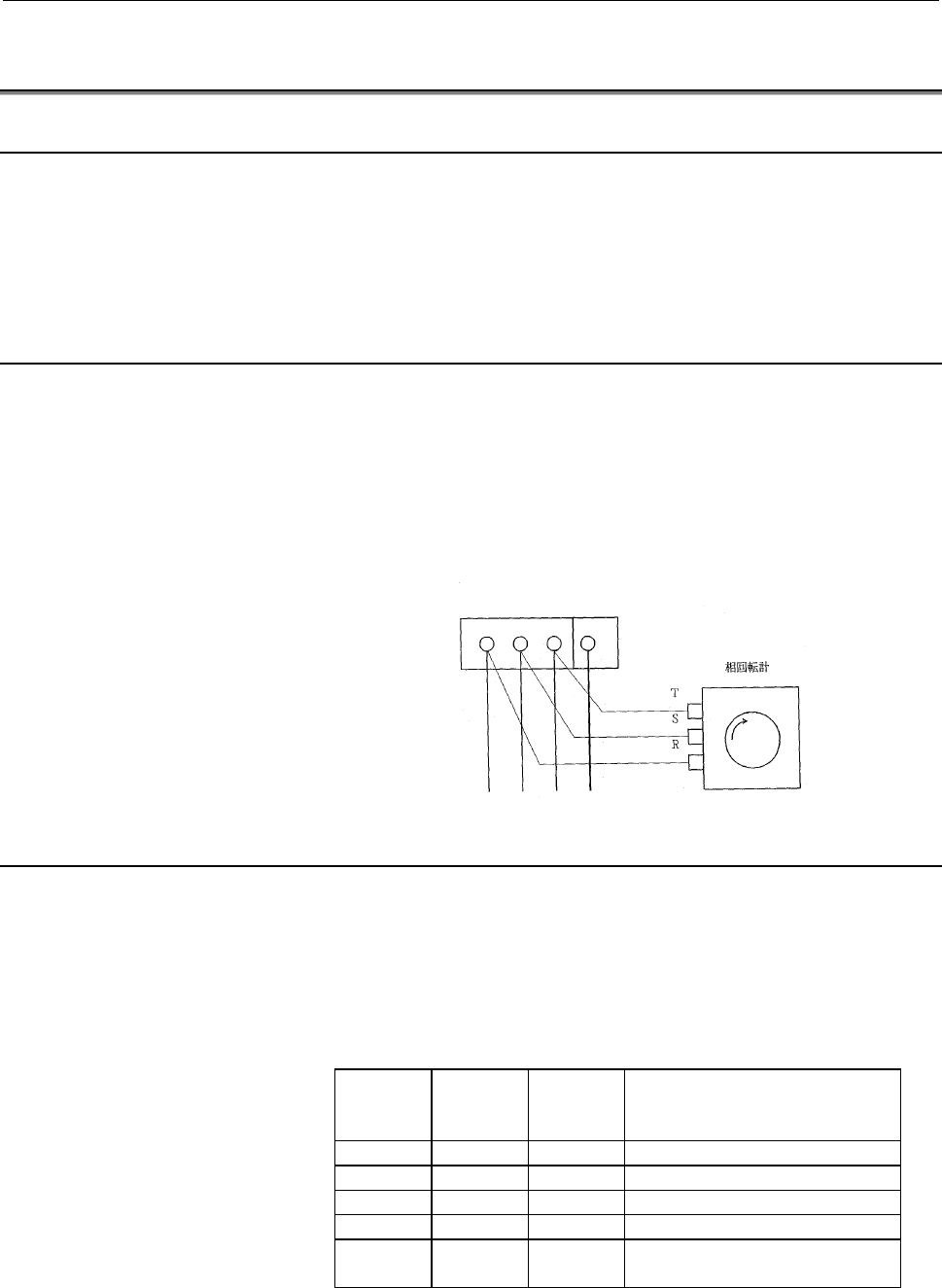
6.5.2 Phase Relation
Using a phase rotation sensor, R, S and T phases of which are
connected to U, V and W phases of the input terminal respectively as
shown in the figure, select the phase of the power line in such a way
that the rotation direction becomes clockwise. In the absence of a
phase relation indicator, complete the connection of the main breaker
so that the exhaust gas is emitted from the laser gas exhaust outlet.
Input terminal
U V W G
(
Class 1 Ground
)
6.5.3 Measurement of Voltage of DC Power Supply Unit
Ascertain if the voltage of each DC power unit is within rated range.
Here refer to Fig.6.5.3(a) for the external view of the IF PCB in the
oscillator. Refer to Fig.6.5.3(b) for the external view of the stabilized
power supply unit.
IF PCB : A16B-2100-0141
(1) Rated output voltage
Terminal
name
Rated
voltage
Voltage
error
allowance
Application
5V 5V ±5% logic circuit
+24V +24V ±10% input, output signal
+15V +15V ±5% analog circuit
-15V -15V ±5% analog circuit
0V 0V -------- Take this 0 V as the base in
measuring voltage.
Contents Summary of Laser C 1000iA Maintenance manual
- Page 1GE Fanuc Automation Europe Computer Numerical Controls Laser-Model C1000 iA Maintenance Manual B-70255EN/01 TECHNOLOGY AND MORE
- Page 2
- Page 3B-70255EN/01 TABLE OF CONTENTS TABLE OF CONTENTS 1 OVERVIEW................................ OVERVIEW................................................................ ................................................................................................ ......................................
- Page 4TABLE OF CONTENTS B-70255EN/01 6 TROUBLESHOOTING ................................................................ ................................................................................................ ..................................................................................... ...
- Page 5B-70255EN/01 TABLE OF CONTENTS 9.1.3 Maximum Output Adjustment.............................................................................................. 118 9.1.4 Check ...............................................................................................................................
- Page 6TABLE OF CONTENTS B-70255EN/01 10.11.3 Replacing a Fan-assisted Radiator ................................................................................... 166 10.12 REPLACING THE POWER SENSOR UNIT........................................................................... 167 10.13 REPLACING THE SH
- Page 7B-70255EN/01 TABLE OF CONTENTS D.6 PARAMETERS FOR POWER CONTROL................................................................................... 217 D.7 PARAMETERS FOR ASSIST GAS PRESSURE AND TIME SETTING................................... 220 D.8 PARAMETERS FOR LASER MAINTENANCE TIMING INDICATION
- Page 8B-70255EN/01 1.OVERVIEW 1 OVERVIEW This manual describes the maintenance of the FANUC LASER- MODEL C1000iA, as well as the structure, configuration, and operation of the laser oscillator. This manual is aimed at those personnel responsible for laser oscillator maintenance. -1-
- Page 91.OVERVIEW B-70255EN/01 1.1 ORGANIZATION OF THE MANUAL This manual is organized as described below. 1. Overview This chapter describes the organization of this manual, applicable models, related manuals, and notes on reading this manual. 2. Safety This chapter describes the handling of lasers, and p
- Page 10B-70255EN/01 1.OVERVIEW 1.2 APPLICABLE MODELS This manual covers the following models: Model Abbreviation FANUC LASER-MODEL C1000iA C1000iA -3-
- Page 111.OVERVIEW B-70255EN/01 1.3 RELATED MANUALS The following manuals are available for the FANUC LASER- MODEL C1000iA: DESCRIPTIONS B-63192EN CONNECTION MANUAL B-63193EN FANUC Series 16i-LA OPERATOR’S MANUAL B-63194EN MAINTENANCE MANUAL B-63195EN PARAMETER MANUAL B-63200EN DESCRIPTIONS B-70252EN OPERAT
- Page 12B-70255EN/01 1.OVERVIEW 1.4 TO USE THE LASER OSCILLATOR SAFETY This manual contains precautions which must be observed during operation of the laser oscillator, to ensure the operator's safety and prevent damage to the oscillator. Each precaution is indicated by "Warning" or "Caution" according to i
- Page 132.SAFETY B-70255EN/01 2 SAFETY This chapter describes precautions to be observed to ensure the safe operation of the laser oscillator. Read this chapter thoroughly before attempting to use the laser oscillator. Also, read the safety precautions in the operator's manual supplied by the machine tool b
- Page 14B-70255EN/01 2.SAFETY 2.1 WARNING (1) It is extremely dangerous to expose your eyes to direct, scattered, or reflected CO2 laser light. Always wear protective glasses while the laser is operating. Exposure to laser light can cause blindness. If your eyes are accidentally exposed, seek medical advice
- Page 152.SAFETY B-70255EN/01 (6) A high voltage of 3 to 4 kV0-p is applied to some places in the laser oscillator cabinet. Therefore, do not turn the power to the oscillator on or operate the oscillator when an oscillator panel is open. Operating the laser oscillator with a panel open can cause a touch on
- Page 16B-70255EN/01 2.SAFETY (12) Do not allow any dangerous or high-pressure gas to get into the oscillator housing. The oscillator cabinet has a hermetic structure (dustproof and dripproof), it cannot be ventilated easily. Flammable gases such as oxygen can cause a fire or explosion. Toxic gases can harm
- Page 172.SAFETY B-70255EN/01 2.2 CAUTION (1) If there is a possibility of being exposed to CO2 laser radiation exceeding the maximum permissible exposure (MPE) level for skin, wear protective clothing. Otherwise, there is a danger of being burnt. (2) FANUC LASER-MODEL C1000iA is fitted with a red semicondu
- Page 18B-70255EN/01 2.SAFETY 2.3 NOTE (1) During installation or maintenance necessitating the opening of an oscillator door or the removal of a panel, only persons who have undergone maintenance training should operate the laser. In such a case, extreme caution must be exercised. (2) Warning labels are af
- Page 192.SAFETY B-70255EN/01 2.4 WARNING LABELS The oscillator uses high voltages and laser beam radiation. Such hazards are indicated with warning labels attached to the positions shown in Fig. 2.4 (a) to (b). Fig. 2.4 (a) Warning label positions (C1000iA : front view) Fig. 2.4 (a) Warning label positions
- Page 20B-70255EN/01 2.SAFETY (1) Class indication label (JPN) (1) Class indication label (FDA) (2) Warning label - 13 -
- Page 212.SAFETY B-70255EN/01 (3) Aperture label (4) Suspension method label (5) Access panel (6) Label inside the access panel - 14 -
- Page 22B-70255EN/01 2.SAFETY (7) Discharge section label (8) Certification label (9) Equipment nameplate (10) Manufacturer's address label (11) Label for regulating the atmospheric gases in the oscillator housing - 15 -
- Page 232.SAFETY B-70255EN/01 2.5 OPTICAL PATHS IN THE OSCILLATOR The figures below show the laser optical paths inside the oscillator. Fig.2.5(a) Optical paths in the C1000iA - 16 -
- Page 24B-70255EN/01 3.INTERNAL STRUCTURE 3 INTERNAL STRUCTURE - 17 -
- Page 253.INTERNAL STRUCTURE B-70255EN/01 3.1 OUTLINE Fig. 3.1 show the internal structure of the laser oscillator. The C1000iA consists of a laser resonator, discharge drive unit, forced gas circulating system, pressure controller, CNC interface, and a protective housing. Fig. 3.1 C1000iA internal structur
- Page 26B-70255EN/01 3.INTERNAL STRUCTURE (2) Discharge drive unit The discharge drive unit consists of a laser power supply, matching box, and discharge tubes. High-frequency output of 2 MHz that is controlled by the CNC discharges the laser gas flows through discharge tubes to energize CO2 molecules. (3)
- Page 273.INTERNAL STRUCTURE B-70255EN/01 3.2 COMPONENT DETAILS This section describes the internal structure of the C1000iA more specifically. Fig. 3.2 is an internal structural drawing. Fig. 3.2 C1000iA structural drawing (1) Resonator The resonator consists of an output mirror, rear mirror, folding mirro
- Page 28B-70255EN/01 3.INTERNAL STRUCTURE (3) Rear mirror A reflecting mirror consisting of a Ge (germanium) substrate, coated with dielectric. Having a high reflectance of 99.5%, the rear mirror is used to reflect the laser beam within the resonator while transmitting 0.5% of the laser light so that the be
- Page 293.INTERNAL STRUCTURE B-70255EN/01 (12) Gas controller The gas controller always monitors the gas pressure in each discharge tube and supplies the fresh laser gas to the circulating system to keep the pressure constant. It also monitors the supply status of the laser gas, purge check for the circulat
- Page 30B-70255EN/01 3.INTERNAL STRUCTURE (19) Matching box The matching box contains a matching circuit, consisting of coils and capacitors, which ensures that power is effectively input to the discharge tubes. (20) Intermediate PCB B This PCB transmits signals output by the shutter section, such as those
- Page 313.INTERNAL STRUCTURE B-70255EN/01 adjusting the optical path of an external optical system and for obtaining a guide for the machining point. - 24 -
- Page 32B-70255EN/01 4.INSTALLATION 4 INSTALLATION - 25 -
- Page 334.INSTALLATION B-70255EN/01 4.1 INSTALLATION PROCEDURE Use the following procedure to make adjustments and checks during installation. (1) Check the environment at the installation location. [Environmental conditions] 1 Ambient +5 to +30 °C temperature 2 Temperature 1.1°C /minute maximum variation 3
- Page 34B-70255EN/01 4.INSTALLATION (2) Remove resonator and shutter clamps. The clamps are used only in transit. In particular, loosen the resonator clamp before it is stored. If the resonator is left for a long time with the clamp tightened, the resonator is likely to be deformed. The clamp locations are
- Page 354.INSTALLATION B-70255EN/01 (3) Check the outsides of units installed in the oscillator as follows: Check items 1 Check whether any printed circuit boards are loose or removed. 2 Check whether any cables are damaged (such as damaged sheathing). 3 Check whether any connectors are loose or detached. 4
- Page 36B-70255EN/01 4.INSTALLATION (7) Check the input power supply voltage, frequency and phase sequence. (See Section 6.5 for details.) (8) Turn on the power, then check the operation of the fan motors in the housing. The fan motors installed in the oscillator start as soon as the power to the CNC is tur
- Page 374.INSTALLATION B-70255EN/01 Model Rated flow rate Pressure loss of the flow path in the oscillator at rated flow rate C1000iA 35 liters/minute 0.12 MPa (e) Stop the chiller unit, then switch the operation mode from manual (local) mode to automatic (remote) mode. (f) If there is no water leakage, set
- Page 38B-70255EN/01 4.INSTALLATION (c) Reset the values of the bits of parameter No. 15025 through parameter No. 15028 to their original values. This completes the check. (13) Perform laser oscillation to achieve discharge aging. If the oscillator is left unused for one week or more, discharge aging is req
- Page 394.INSTALLATION B-70255EN/01 4.2 PREPARATION PRIOR TO SHIPMENT For shipment and transportation, follow the steps explained below. (1) Disconnect all CNC connecting cables. (2) Disconnect the power cable and ground cable. (3) Remove the laser gas pipes, and attach blanking plugs to the pipes to preven
- Page 40B-70255EN/01 4.INSTALLATION 4.2.1 Packing for Transportation Prior to shipment and transportation, the packing and checking operations described below must be performed. Specifications of the FANUC LASER-MODEL C1000iA (1) External dimensions : See the external views. (2) Weights : About 350 kg (osci
- Page 414.INSTALLATION B-70255EN/01 4.2.2 Removing Cooling Water Remove cooling water according to the procedure below. (1) Open the cooling water inlet (IN) and outlet (OUT), and leave both open. Cooling water will stop draining from the unit after about 10 minutes. (2) Once the cooling water has stopped d
- Page 42B-70255EN/01 4.INSTALLATION 4.3 DETAILS OF CHECKING External gas piping leakage check (clamp test) (1) Using an approved gas pipe, connect the gas inlet of the oscillator to the cluster piping, or to the secondary side of the regulator mounted on the gas cylinder. CAUTION As the external gas piping,
- Page 434.INSTALLATION B-70255EN/01 (d) Upon the completion of this check, close the main valve of the gas cylinder. CAUTION Periodically check the external gas piping for leakage. Parameter check Laser oscillator parameter data sheets are attached to each oscillator. Machine tool builders may prepare a par
- Page 44B-70255EN/01 4.INSTALLATION (6) Check the gas pressure on the diagnosis screen to determine whether there is any increase in pressure over 15 minutes. An increase in pressure of within 10 is normal. (7) After completing the check, turn on the start switch. Then, after two to three seconds, turn off
- Page 454.INSTALLATION B-70255EN/01 (6) After completing the check, reset the value set in (3) above to the original setting. Oscillation characteristics (1) Modify the parameters listed below. PRM No.15000 bit 4 Setting ® 1 (Three-minute correction is enabled.) PRM.No.15008 bit 6 1 ® 0 (Automatic aging is
- Page 46B-70255EN/01 4.INSTALLATION (2) If the setting in parameter No. 15223 is changed, a warning message indicating a parameter change appears when LRDY is set. Clear the message by resetting. (3) Remove the top panel of the oscillator so that you can check the discharge tubes and trigger electrode. (4)
- Page 474.INSTALLATION B-70255EN/01 An alarm, if issued in step (5), check the external laser gas piping and laser gas composition, or perform aging. Beam mode check (1) Remove the guide pipe or the first bend mirror located between the exit of the laser beam of the oscillator and machine. (2) Start the osc
- Page 48B-70255EN/01 4.INSTALLATION Discharge aging If the oscillator is left unused for a long time (three days or more), or if the laser gas circulating system has been opened to the atmosphere (for example, to clean the mirrors or replace gas system components), aging is required. This involves warming u
- Page 494.INSTALLATION B-70255EN/01 (4) After 15 minutes has passed, set the RUN key to OFF to stop the oscillator. (6) Reset the discharge gas pressure to the normal value, perform internal discharge operation with the specified output level for 15 minutes, then perform purge operation. (7) Repeat step 6)
- Page 50B-70255EN/01 4.INSTALLATION 4.4 OSCILLATOR CONNECTIONS The oscillator has connections for cooling water piping, laser gas piping, and power and signal cables. For details of the electrical connections for the CNC and machine, refer to the corresponding connection manual. 4.4.1 Cooling Water 4.4.1.1
- Page 514.INSTALLATION B-70255EN/01 [Reference] Cooling water capacity of the oscillator Model Water capacity C1000iA About 5 liters 4.4.1.3 Cleaning agent To remove foreign matters such as fur that have adhered to the inside of the cooling water circulating path, wash the cooling water circulating path usi
- Page 52B-70255EN/01 4.INSTALLATION 4.4.1.5 Pure Water Supply Unit It is recommended that a pure water supply unit (ion-exchange resin) be installed at the water inlet of the chiller. The pure water supply unit can prevent problems with the oscillator from occurring due to corrosion or a clogged pipe. Repla
- Page 534.INSTALLATION B-70255EN/01 4.4.2 Laser Gas 4.4.2.1 Laser gas specification Supply the laser oscillator with a mixture of gases that satisfy the conditions listed below. (1) Composition ratio and accuracy CO2 : 5±0.25% He : 40±2.00% N2 : 55±2.75% (N2 balance) (2) Water (H2O): 5 ppm or less (3) Hydro
- Page 54B-70255EN/01 4.INSTALLATION 4.4.3 Electrical Connections Connect the cables to the laser oscillator as described below. (1) Power cable U(R) V(S) W(T) Power supply: 200VAC +10% 50/60Hz ±1Hz 3f -15% or 220VAC +10% 60Hz ±1Hz 3f -15% (2) Ground cable Connect the ground cable to the ground connection se
- Page 555.MAINTENANCE B-70255EN/01 5 MAINTENANCE In FANUC LASER-MODEL C1000iA, periodic inspection items have been reduced, and adjustments have been made easy. To keep the oscillator in a satisfactory operating condition over a long period, however, it is necessary to carry out periodic maintenance (includ
- Page 56B-70255EN/01 5.MAINTENANCE 5.1 DAILY INSPECTION Table 5.1 lists daily inspection items. Inspect the C1000iA according to this table. When parts (including oil) have been used for a prescribed period, replace them quickly. Table 5.1 Daily inspection items Item Period Content and instruction 1 Residua
- Page 575.MAINTENANCE B-70255EN/01 5.2 PERIODIC MAINTENANCE The C1000iA contains consumables that must be replaced periodically. Table 5.2(a) or (b) lists such consumables and the related periodic maintenance work. Perform periodic maintenance as well as daily inspection described in Section 5.1 by using th
- Page 58B-70255EN/01 5.MAINTENANCE 5.3 DETAILS OF MAINTENANCE When opening the panels and doors during maintenance, keep the power turned off. Before replacing oil, be sure to check that purging is completed. 5.3.1 Changing the Turbo Blower Oil Check method Check the amount of oil in the turbo blower while
- Page 595.MAINTENANCE B-70255EN/01 between L and H. Either superfluous or insufficient oil can be a cause of trouble. (3) Lightly wipe the area around the oil inlet, hexagonal-head screw on the oil inlet, and O-ring with a clean cloth or paper, then check that there are no foreign matters. Foreign matters g
- Page 60B-70255EN/01 5.MAINTENANCE 5.3.2 Changing the Exhaust Pump Oil Check method Watch the oil gauge, and check that the oil level is between graduations L and H. Also check whether the oil is dark.If the oil level is below L, add oil to the turbo blower or replace the oil in it. If the oil level is abov
- Page 615.MAINTENANCE B-70255EN/01 Replacement method (1) Stop the oscillator, and turn off the power. (2) Remove the oil inlet plug. There is an O-ring on it. Be careful not to damage it. A missing or damaged O-ring can lower the exhaust capacity of the pump. (3) Insert the drain tube into a drain oil pot.
- Page 62B-70255EN/01 5.MAINTENANCE 5.3.3 Replacing the Exhaust Pump Filter Replacement method When the operation time reaches 3000 hours or the exhaust capacity gets lowered, replace the filter. A clogged filter may cause a whitish smoke of oil mist to come out of the pump or lower the exhaust capacity. (1)
- Page 635.MAINTENANCE B-70255EN/01 5.4 MAINTENANCE PARTS The maintenance parts are listed below. Refer to the following tables for maintenance unit and part specification information. The part specifications for oscillators compatible with CE marking are not listed below. [Nonrepairable parts] Name Specific
- Page 64B-70255EN/01 5.MAINTENANCE [Nonrepairable parts] Name Specification Q'ty 37 Gas filter A97L-0201-0771/H-0.5-B 1 38 Nylon ferrule 1/4” A98L-0004-0348/2-N 6 39 Nylon ferrule 3/8” A98L-0004-0348/3-N 6 40 Nylon ferrule 1/2” A98L-0004-0348/4-N 2 41 Shutter mirror A290-4514-X206 1 42 Shutter mirror (for g
- Page 656.TROUBLESHOOTING B-70255EN/01 6 TROUBLESHOOTING - 58 -
- Page 66B-70255EN/01 6.TROUBLESHOOTING 6.1 TROUBLESHOOTING PROCEDURE The troubleshooting procedure to be applied depends on the failure occurrence status as indicated below. Perform checking according to the items listed below. (1) Action in response to alarm screen display (See Sections 6.2 and 6.3.) (2) M
- Page 676.TROUBLESHOOTING B-70255EN/01 6.2 ERROR MESSAGES AND COUNTERMEASURES See the conceptual diagram of alarm processing and the list of error code in the Appendix C. - 60 -
- Page 68B-70255EN/01 6.TROUBLESHOOTING 6.3 RESPONDING TO ALARM MESSAGES ON THE SCREEN The alarm numbers, DGNs, and parameter Nos. are of the FS16i-L. ALM No.4061 AD converter 1 is not normal. Alarm output condition This alarm is issued when the A/D converter 1 does not return the conversion completion signa
- Page 696.TROUBLESHOOTING B-70255EN/01 Alarm output condition This alarm is issued when any or all of the signals from bits 0 to 7 at address 06H in DI of the laser interface are set to 0 in LRDY or a later step of the sequence. Note that the bits not set in parameter No. 15025 or 15027 are not checked. Rel
- Page 70B-70255EN/01 6.TROUBLESHOOTING Phenomenon Presumption cause 5 The RF voltage of all the units is high during The external laser gas discharge and the laser power is low. The pipe is abnormal. discharge tends to disappear. When the purge The gas composition is repeatedly performed, the RF voltage is
- Page 716.TROUBLESHOOTING B-70255EN/01 ALM No.4065 Shutter anomaly Alarm output condition This alarm is issued when the shutter open command and the shutter status do not match in LRDY or a later step of the sequence. Shutter open signal SHOP (bit 0 at address 05H of DO of the laser interface) Shutter statu
- Page 72B-70255EN/01 6.TROUBLESHOOTING Alarm output condition When HV is turned on, discharge starts six seconds later to reach the maximum bias command value. After the time set in parameter No. 15222 is passed, the voltage value of each discharge tube is compared with the value set in parameter No. 15221.
- Page 736.TROUBLESHOOTING B-70255EN/01 Cause of trouble Solution 4 Anomaly of temperature Check the continuity of the temperature sensor sensor. If any disconnection is found, replace the temperature sensor. 5 Anomaly of oscillator IF Replace the faulty PCB. PCB(A16B-2100-0141) 6 Anomaly of connecting Check
- Page 74B-70255EN/01 6.TROUBLESHOOTING Alarm output condition This alarm is issued when the enable signal in the interface becomes 0 during the time from RUN-ON to immediately before purge completion. Enable signal in the interface EN (bit 0 at address 00H of DI of the laser interface) Related parameters DG
- Page 756.TROUBLESHOOTING B-70255EN/01 Related parameters G221#7 AGRDY Assist gas ready signal G222#5 AGST Assist gas start signal F222#2-#0 AG1-AG3 Assist gas selection signal ALM No.4072 Shortage of cooling water This alarm appears when the water shortage takes place. Alarm output condition When the chill
- Page 76B-70255EN/01 6.TROUBLESHOOTING Related parameters PRM.15009#7 TEM Tank supply pressure DGN.960#5 *MGP Laser gas supply pressure sensor Cause of trouble Solution 1 Tool low supply pressure Adjust the secondary pressure at the regulator of laser gas on the gas cylinder so that the pressure of laser ga
- Page 776.TROUBLESHOOTING B-70255EN/01 Cause of trouble Solution 4 Anomaly in temperature sensor The temperature sensor is designed to be actuated by temperatures of 60°C or above. If the temperature sensor is actuated at lower temperatures, replace the sensor. ALM No.4075 Condensation A condensation sensor
- Page 78B-70255EN/01 6.TROUBLESHOOTING Cause of trouble Solution 1 Lack of output from The thermocouple inside the power sensor unit may laser power sensor be damaged, or there may be a poor terminal unit connection. Measure the direct current resistance between the terminals of the power sensor unit, and c
- Page 796.TROUBLESHOOTING B-70255EN/01 Alarm output condition This alarm is issued when the actual gas pressure deviates by ±100 or more from the set level in LRDY or a later step. Monitoring, however, is not performed during the time from HV OFF until LRDY. Related parameters DGN.905 Actual gas pressure Ca
- Page 80B-70255EN/01 6.TROUBLESHOOTING ALM No.4080 Leakage of gas tube/anomaly of exhaust pump When the RUN (pressure control start) button is pressed, the exhaust pump starts evacuating the gas in the circulating system to place the oscillator in the low-pressure state. This alarm occurs when the pressure
- Page 816.TROUBLESHOOTING B-70255EN/01 Cause of trouble Solution 5 Anomaly of exhaust If the above checks do not reveal any pump abnormality, the performance of the exhaust pump has deteriorated. Check the following items. 1) The oil level is too low. Supply oil as explained in Chapter 5. 2) Other than the
- Page 82B-70255EN/01 6.TROUBLESHOOTING Cause of trouble Solution 2 Gas leakage from 1) Check whether any component joints of the gas piping circulating system are loose. If a loose joint is found, tighten the joint firmly. 2) Check whether any components of the gas circulating system are cracked. If a crack
- Page 836.TROUBLESHOOTING B-70255EN/01 ALM No.4085 Decrease of laser output power This alarm appears when the laser output power decreases and takes an abnormally higher calibration coefficient. Alarm output condition This alarm is issued when the power compensation coefficient exceeds the power compensatio
- Page 84B-70255EN/01 6.TROUBLESHOOTING Cause of trouble Solution 1 Contamination of shutter mirror Clean the shutter mirror. If this alarm recurs after the shutter mirror is cleaned, replace the mirror. 2 Anomaly of temperature sensor Replace the temperature sensor. 3 Temperature sensor cable Replace the ca
- Page 856.TROUBLESHOOTING B-70255EN/01 Cause of trouble Solution turbo blower gas inverter are normal. Replace the turbo blower or circulating high-frequency inverter if found to be faulty. performance ALM No.4089 Assist gas not output This alarm is issued, if an attempt is made to radiate a laser beam, whe
- Page 86B-70255EN/01 6.TROUBLESHOOTING ALM No.4095 A/D CONVETER-3 This alarm is issued when A/D converter 3 does not return the conversion completion signal in the specified time after the converter starts conversion. This A/D converter is designed for reading the amount of tracing displacement. ALM No.4096
- Page 876.TROUBLESHOOTING B-70255EN/01 Cause of trouble Solution 2 Gas leakage from 1) Check whether any component joints of the gas internal piping circulating system are loose. If a loose joint is found, tighten the joint firmly. 2) Check whether any components of the gas circulating system have cracked.
- Page 88B-70255EN/01 6.TROUBLESHOOTING ALM No.4101 OUT OF FREQUENCY 1 This alarm is issued, if a frequency reached signal is not received within 120 seconds after the turbo blower is started. Alarm output condition This alarm is issued when the frequency reach 1 signal does not become 1 within 120 seconds a
- Page 896.TROUBLESHOOTING B-70255EN/01 Cause of trouble Solution 4 Anomaly of cable Check whether the cable is securely connected to connection the turbo PCB. If not, reattach the cable. ALM No.4106 BLOWER OIL SHORTAGE This alarm is issued if the signal from the turbo blower oil sensor indicates that the oi
- Page 90B-70255EN/01 6.TROUBLESHOOTING ALM No.4132 PARAMETER WAS CHANGED Alarm output condition This alarm is issued when the setting in parameter No. 15223, 15242, or 15243 is altered in LRDY or a later step. Related parameters PRM.15223 Discharge bias command value PRM.15242,15243 Intra-tube pressure sett
- Page 916.TROUBLESHOOTING B-70255EN/01 6.4 MAJOR FAULTS 6.4.1 Laser Power Supply Alarm Display (1) If an alarm is issued to indicate the occurrence of a power supply fault, check the diagnosis screen to determine which power supply unit issued that alarm signal. The bit corresponding to the power supply uni
- Page 92B-70255EN/01 6.TROUBLESHOOTING Type of alarm Source Major causes RFI This alarm is issued if a high RF current flows through the discharge tube when the oscillator is operating in CW/pulse mode. If the power supply unit fails just because the high-speed diode or FET module is damaged, the power supp
- Page 936.TROUBLESHOOTING B-70255EN/01 If there exists any anomaly in the results of the above investigations, replace the anomalous component. 6.4.6 Electromagnetic Contactor of Exhaust Pump Trips Thermally Possible causes are listed below. Take appropriate action. Cause of trouble Solution 1 Anomalous set
- Page 94B-70255EN/01 6.TROUBLESHOOTING 6.4.8 Excessive Laser Gas Consumption Possible causes are listed below. Take appropriate action. Cause of trouble Solution 1 Gas leakage between Ascertain the following. gas cylinder and 1) Anomalous mounting of regulator. oscillator 2) Anomalous connection between tub
- Page 956.TROUBLESHOOTING B-70255EN/01 Causes of inverter alarms (Model : SJH300) Message Contents Cause power (supply voltage increase) E16 Protection against instantaneous power Momentary loss of supply failure voltage E21 Temperature increase (supply voltage Inverter faulty increase) E23 Gate array error
- Page 96B-70255EN/01 6.TROUBLESHOOTING Display method d081 (Function/FUNC keys) (1) E01.3 (Up/Down keys) (2) 1000 (Up/Down keys) (3) 28.0 (Up/Down keys) (4) 280 (Up/Down keys) (5) 15 (Up/Down keys) (6) 18 (Up/Down keys) - 89 -
- Page 976.TROUBLESHOOTING B-70255EN/01 6.5 OBSERVING VOLTAGE OF POWER LINE 6.5.1 Measurement of Voltage Ascertain the followings, (1) line voltage: 200/220VAC, +10%, -15% (2) frequency: 50/60Hz ±1Hz (3) 3 phases Here the combination of 220 V and 50 Hz is prohibited. 6.5.2 Phase Relation Using a phase rotati
- Page 98B-70255EN/01 6.TROUBLESHOOTING (2) Fuse used on the IF PCB FU3 : A60L-0001-0175#3.2 For +5V(3.2A) (3) Stabilized power supply unit Fig. 6.5.3 (b) shows the external appearance of +24V stabilized power unit. Designation of power supply unit : A20B-1005-0124 Designation of fuse FU : A60L-0001-0175#3.2
- Page 996.TROUBLESHOOTING B-70255EN/01 6.5.4 Checking the IF PCB Signals By using the IF PCB pins, check that each signal of the IF PCB is normal. Fig. 6.5.3(a) show the pin locations. Signal Signal function COR Voltage to operate the laser power supply 0 to 5V GPC Specification of pressure inside the laser
- Page 100B-70255EN/01 6.TROUBLESHOOTING 6.6 INDICATION OF STATE BY MEANS OF SELF DIAGNOSTIC FUNCTION When the machine breaks down, it is necessary to know if the trouble is in the CNC, PMC, machine or laser. Even when there does not exist machine failure, the machine might hang-up for waiting of external sig
- Page 1016.TROUBLESHOOTING B-70255EN/01 CNC®®PMC status display #7 #6 #5 #4 #3 #2 #1 #0 F220 MWRM SHTONL SHTOFL MWRM Laser power alarm signal SHTONL Shutter on state signal SHTOFL Shutter off state signal #7 #6 #5 #4 #3 #2 #1 #0 F221 BEAM LSTR RFHV CLON WAIT PURGE LRDY LARM BEAM Beam on signal LSTR In-oscill
- Page 102B-70255EN/01 6.TROUBLESHOOTING 904 GAS PRES. CONTROL Displays a value specified in a pressure command for the pressure controller that controls pressure inside the discharge tube, and sent to the DA converter. 905 LASER TUBE PRES. Displays the pressure inside the discharge tube. Display range : 0 to
- Page 1036.TROUBLESHOOTING B-70255EN/01 921 RF VOLTAGE 7 922 RF CURRENT 7 923 RF VOLTAGE 8 924 RF CURRENT 8 Voltage (V) and current (mA) of discharge tubes 1 to 8 (strictly speaking, power supply units) 925 DC VOLTAGE 1 926 DC CURRENT 1 927 DC VOLTAGE 2 928 DC CURRENT 2 929 DC VOLTAGE 3 930 DC CURRENT 3 931
- Page 104B-70255EN/01 6.TROUBLESHOOTING 910 DCW 5 910 DCW 6 910 DCW 7 910 DCW 8 Injection power of power supplies 1 to 8 (valid when bit 5 of parameter No. 15008 is 1). Unit : W #7 #6 #5 #4 #3 #2 #1 #0 960 *SFI *RBT *MGP *AP FRQ *ESA *EN *EN Intra-IF enable signal 0 : Disabled 1 : Enabled *ESA Emergency stop
- Page 1056.TROUBLESHOOTING B-70255EN/01 *RAL Exhaust pump alarm 0 : Abnormal 1 : Normal SON Open shutter sensor The shutter is open when this bit is set to 1. SOF Closed shutter sensor The shutter is closed when this bit is set to 1. *SHT Shutter temperature sensor 0 : Abnormal 1 : Normal *ABT Absorber tempe
- Page 106B-70255EN/01 6.TROUBLESHOOTING *TC2 Turbo current sensor 2 0 : Abnormal 1 : Normal *OH2 Abnormal turbo temperature 2 0 : Abnormal 1 : Normal #7 #6 #5 #4 #3 #2 #1 #0 964 *OH3 *TC3 *RV3 *VB3 *AR3 *IA3 *IA3 Inverter alarm 3 0 : Abnormal 1 : Normal *AR3 Frequency signal 3 0 : Mismatch 1 : Match *VB3 Vib
- Page 1076.TROUBLESHOOTING B-70255EN/01 SP2 Pressure/power select signal HSC High-speed A/D conversion start #7 #6 #5 #4 #3 #2 #1 #0 970 PS08 PS07 PS06 PS05 PS04 PS02 PS02 PS01 PS01 to PS08 Power select signals 1 to 8 0 : Not selected 1 : Selected #7 #6 #5 #4 #3 #2 #1 #0 972 TWV BPV PTL GRY VEN RPA RBA PUG P
- Page 108B-70255EN/01 6.TROUBLESHOOTING IB Semiconductor laser-on command 0 : OFF 1 : ON FW Inverter start signal 0 : Stopped 1 : Started PCS Gas pressure PWM command 0 : OFF 1 : ON LSC Low speed A/D conversion start 0 : OFF 1 : ON #7 #6 #5 #4 #3 #2 #1 #0 974 PSAR8 PSAR7 PSAR6 PSAR5 PSAR4 PSAR3 PSAR2 PSAR1 P
- Page 1097.OSCILLATOR CONNECTIONS B-70255EN/01 7 OSCILLATOR CONNECTIONS - 102 -
- Page 110B-70255EN/01 7.OSCILLATOR CONNECTIONS 7.1 ELECTRICAL CONNECTIONS An electrical connection diagram for the C1000iA is given below. Fig.7.1 Electrical connection diagram for C1000iA (1/2) - 103 -
- Page 1117.OSCILLATOR CONNECTIONS B-70255EN/01 Fig.7.1 Electrical connection diagram for C1000iA (2/2) - 104 -
- Page 112B-70255EN/01 7.OSCILLATOR CONNECTIONS 7.2 COOLING WATER PIPING A cooling water flow diagram for the C1000iA is given below. Fig.7.2 (a) Water flow diagram for C1000iA - 105 -
- Page 1137.OSCILLATOR CONNECTIONS B-70255EN/01 7.3 VACUUM GAS CONNECTION A vacuum system diagram for the C1000iA is given below. Fig. 7.3 Vacuum system diagram for C1000iA - 106 -
- Page 114B-70255EN/01 8.OSCILLATOR CONNECTIONS 8 OSCILLATOR CONNECTIONS - 107 -
- Page 1158.OSCILLATOR CONNECTIONS B-70255EN/01 8.1 UNIT CONFIGURATION The input unit consists of a power magnetics cabinet, interface PCB, and stabilized power supply. Fig. 8.1(a) shows the power magnetics cabinet configuration, and Figs. 8.1(b) through (d) show the input units. QF1 QF2 KM1 To laser power su
- Page 116B-70255EN/01 8.OSCILLATOR CONNECTIONS Fig.8.1(b) Input unit 1 (C1000iA, Japan, U.S.A.) Fig.8.1(c) Input unit 2 (C1000iA, Japan) - 109 -
- Page 1178.OSCILLATOR CONNECTIONS B-70255EN/01 Fig.8.1(d) Input unit 2 (C1000iA, U.S.A.) - 110 -
- Page 118B-70255EN/01 8.OSCILLATOR CONNECTIONS 8.2 RELAY PCB B Relay PCB B is used to group signals sent from the shutter section and to output the grouped signals to the interface PCB. CN59 is an output terminal for connecting a measuring instrument used in alignment. Fig. 8.2 shows the layout of relay PCB
- Page 1198.OSCILLATOR CONNECTIONS B-70255EN/01 8.3 GAS CONTROLLER The gas controller consists of components such as a suction unit, exhaust unit, and pressure sensor. Fig.8.3(a) shows installation, and Fig.8.3(b) shows piping of the gas controller respectively. The functions of each of the components shown i
- Page 120B-70255EN/01 8.OSCILLATOR CONNECTIONS (8) Pressure control valve This valve is provided to maintain a specified laser gas pressure in the oscillator. The valve is consistently and precisely opened or closed according to commands issued from the CNC, controlling the flow rate of the fresh laser gas s
- Page 1218.OSCILLATOR CONNECTIONS B-70255EN/01 Fig.8.3(b) Block diagram of gas controller - 114 -
- Page 122B-70255EN/01 9.SETTING AND ADJUSTMENT 9 SETTING AND ADJUSTMENT - 115 -
- Page 1239.SETTING AND ADJUSTMENT B-70255EN/01 9.1 LASER POWER SUPPLY UNIT This unit is precisely adjusted at the factory and should not require any further adjustment. If the power supply unit, matching box, or discharge tube is replaced, however, the unit should be set and adjusted as described below. When
- Page 124B-70255EN/01 9.SETTING AND ADJUSTMENT 9.1.2 Base Discharge Adjustment 9.1.2.1 Rewriting the parameter Rewrite the parameters according to the table below. (Upon completion of adjustment, return the parameters to the original values.) Table 9.1.2.1 Parameters to be modified before starting adjustment
- Page 1259.SETTING AND ADJUSTMENT B-70255EN/01 turning off HV, turn on HV and check that stable discharge is maintained for 5 minutes. Until this stable discharge state is confirmed, repeat this step. (8) Turn off HV, then set 2850 in PRM 15223 for specifying a bias command value. (See Section 9.1.6.) (9) Wh
- Page 126B-70255EN/01 9.SETTING AND ADJUSTMENT (5) After output of the maximum command value, wait 3 minutes. Record the DCV, DCI, RFV, and RFI values of each power supply. Then, check that the value of RFV does not exceed the maximum RFV (Table 9.1.7). 9.1.4.2 Pulse Output Test Output the pulse test command
- Page 1279.SETTING AND ADJUSTMENT B-70255EN/01 9.1.7 Checking of Electric Shutter Operation (1) Insert heat-sensitive paper into the laser optical path after passing through the shutter mirror. (2) output the continuous rated command value for 3 minutes. Then, execute the following program (specifying OW for
- Page 128B-70255EN/01 9.SETTING AND ADJUSTMENT 9.2 TURBO PCB These PCBs are precisely adjusted at the factory and should not require any further adjustment. If the turbo blower or turbo PCB is replaced, however, VR1 to VR4 should be adjusted and set oil level censor as described below. (1) Prior to activatin
- Page 1299.SETTING AND ADJUSTMENT B-70255EN/01 (7) In the alarm state, adjust trimmer VR1 so that VC (voltage across VA1 and 0V) matches the following value: VC=VSO´0.778 (8) Press the reset key of the NC. Check that the alarm is reset. NOTE VR1 is three-turn trimmers. - 122 -
- Page 130B-70255EN/01 9.SETTING AND ADJUSTMENT 9.3 HIGH-FREQUENCY INVERTER Connection The following cables are connected to the inverter: R, S, T : Main power input U, V, W Inverter output G : Grounding 1 : Reset signal 2 : Soft lock signal 8 : Inversion command signal AL0, AL1 : Relay contact output (ON : N
- Page 1319.SETTING AND ADJUSTMENT B-70255EN/01 (1) Names and descriptions of the components of the digital operator's panel Name Description Monitor Displays settings such frequency and output current values. RUN (operation) Turned on when the inverter is running. lamp Program lamp Turned on when the monitor
- Page 132B-70255EN/01 9.SETTING AND ADJUSTMENT (2) Method of operation (a) Method of displaying the monitor mode, basic setting mode, and extended function mode Monitor (4-digit LED display) <1> Display of set monitor state <5> The code No. of the monitor mode is (In the initial state, 0.00 is displayed.) di
- Page 1339.SETTING AND ADJUSTMENT B-70255EN/01 (b) Function setting method Change the operation command destination (operator ® control terminal). <1> The extended function mode is displayed. <5> The extended function mode is displayed. (A--- is (A--- is displayed.) displayed.) Display "A---" according to th
- Page 134B-70255EN/01 9.SETTING AND ADJUSTMENT (c) Function code setting method The code No. of the monitor mode, basic setting mode, or extended function monitor can be directly entered instead of using the scroll method. An example of changing from monitor mode code No. d001 to function code No. A029 is in
- Page 1359.SETTING AND ADJUSTMENT B-70255EN/01 Parameter settings Initial Setting Code Name of function Remarks value value d001 Output frequency monitor - - Hz d002 Output current monitor - - A d003 Rotation direction monitor - - F (forward rotation)/o (stop)/r (reverse rotation) d004 PID feedback monitor -
- Page 136B-70255EN/01 9.SETTING AND ADJUSTMENT Initial Setting Code Name of function Remarks value value 00: Free run at JG stop time (disabled during operation), 01: Gradual stop at JG stop time (disabled during operation), 02: Multistage Direct current damping at JG stop time (disabled during speed A039 Jo
- Page 1379.SETTING AND ADJUSTMENT B-70255EN/01 Initial Setting Code Name of function Remarks value value A101 01 start 0.00Hz 0.00Hz 0.00 to 1500 A102 01 end 0.00Hz 0.00Hz A103 01 start ratio 20% 20% 0 to 100 External A104 01 end ratio 100% 100% frequency A105 01 start selection 01 01 00: External start freq
- Page 138B-70255EN/01 9.SETTING AND ADJUSTMENT Initial Setting Code Name of function Remarks value value C001 Intelligent input terminal 1 selection 18 18 01: RV (reverse rotation), 02: CF1 (multistage speed 1), 03: CF2 (multistage speed 2), 04: CF3 (multistage 3), 05: CF4 C002 Intelligent input terminal 2 s
- Page 1399.SETTING AND ADJUSTMENT B-70255EN/01 Initial Setting Code Name of function Remarks value value b034 Run time/power ON time level 0hr 0hr 0. to 9999.(0 to 99990hr)/1000 to 6553(100000 to 655300)hr 00: Forward and reverse rotation enabled, 01: Forward b035 Operation direction limitation selection 00
- Page 140B-70255EN/01 9.SETTING AND ADJUSTMENT 9.4 GAS CONTROLLER This unit is precisely adjusted at the factory and should not require any further adjustment. If the intake unit, exhaust unit, or atmospheric pressure unit is replaced or requires re-adjustment, however, it should be set and adjusted as descr
- Page 1419.SETTING AND ADJUSTMENT B-70255EN/01 (3) Remove the orange gas tube by loosening the hexagon cap nuts securing the tube. This causes the atmospheric pressure sensor to detect the atmospheric pressure. (4) Clear the sensor to zero according to Section 9.5. Reinstall the removed gas tube, and resecur
- Page 142B-70255EN/01 9.SETTING AND ADJUSTMENT 9.4.3 Adjusting the Exhaust Unit (Adjusting the Laser Gas Consumption) (1) Remove the piping from the filter of the gas controller, then attach a gas meter for laser gas. (2) Set PRM No. 15260 to 30, then start the oscillator. Air taken in when the outlet is ope
- Page 1439.SETTING AND ADJUSTMENT B-70255EN/01 Fig. 9.4 Details of C1000iA gas controller sensor and flow rate adjustment valve - 136 -
- Page 144B-70255EN/01 9.SETTING AND ADJUSTMENT 9.5 SETTING THE GAS SUPPLY PRESSURE SENSOR AND ATMOSPHERIC PRESSURE SENSOR The sensors operate in one of four modes. In the measurement mode, a pressure value being measured is indicated. In the initial setting mode, basic operation is set. In the pressure setti
- Page 1459.SETTING AND ADJUSTMENT B-70255EN/01 - UP ( ) and DOWN ( ) buttons: Used to change the mode and settings. - SET button: Used to change the mode and set a value finally. NOTE The indicator section of the sensor indicates a pressure value as a gauge pressure in MPa. - 138 -
- Page 146B-70255EN/01 9.SETTING AND ADJUSTMENT 9.5.2 Setting Procedure When setting in each mode, follow the procedure described below. Setting in the initial setting mode Perform basic setting for the sensor. To enter the initial setting mode, hold down the SET key for 2 to 4 seconds in the measurement mode
- Page 1479.SETTING AND ADJUSTMENT B-70255EN/01 Setting in the pressure setting mode Perform operating pressure setting for the sensor. Note that different values are set for the gas supply pressure sensor and atmospheric pressure sensor. List of settings (Unit: MPa) Gas supply pressure sensor Atmospheric pre
- Page 148B-70255EN/01 9.SETTING AND ADJUSTMENT Zero clear Clear the initial offset value of the sensor. This setting can be made in the measurement mode. Set the atmospheric pressure sensor only. Check that the measurement mode is set. Press and simultaneously. Set the indication to 0. To the measurement mod
- Page 1499.SETTING AND ADJUSTMENT B-70255EN/01 9.6 SETTING THE POWER INPUT COMPENSATION COEFFICIENT This coefficient is precisely adjusted at the factory and should not require any further adjustment. If the rear mirror in the laser oscillator is replaced, or the power sensor unit is replaced, however, check
- Page 150B-70255EN/01 9.SETTING AND ADJUSTMENT 9.7 WATER FLOW SENSOR This sensor is precisely adjusted at the factory and should not require any further adjustment. If the water distribution unit or water flow sensor is replaced, however, this sensor should be set and adjusted as described below: 9.7.1 Adjus
- Page 1519.SETTING AND ADJUSTMENT B-70255EN/01 (7) Reinstall the removed packing and reconnect the detached cables to the terminal block. - Supplement - If a flowmeter is unavailable, a temporary setting can be made by positioning the flow rate indicator as shown in Fig. 9.7.1. Fig. 9.7.1 Flow rate indicator
- Page 152B-70255EN/01 10.REPLACEMENT PROCEDURES 10 REPLACEMENT PROCEDURES - 145 -
- Page 15310.REPLACEMENT PROCEDURES B-70255EN/01 10.1 INPUT UNIT 10.1.1 Replacing the Stabilized Power Supply Replace the stabilized power supply as follows: (1) Turn off the power to the CNC, then turn off the power to the laser oscillator. In addition, open the main circuit breaker for the laser oscillator.
- Page 154B-70255EN/01 10.REPLACEMENT PROCEDURES 10.1.3 Replacing the IF PCB on the Oscillator Side Replace the IF PCB on the oscillator side as follows: (1) Turn off the power to the CNC, then turn off the power to the laser oscillator. In addition, open the main circuit breaker for the laser oscillator. (2)
- Page 15510.REPLACEMENT PROCEDURES B-70255EN/01 10.2 REPLACING THE LASER POWER SUPPLY Figs. 10.2 (a) to (c) show the laser power supply. Replace the laser power supply as described below. Fig. 10.2(a) - 148 -
- Page 156B-70255EN/01 10.REPLACEMENT PROCEDURES Fig. 10.2(b) - 149 -
- Page 15710.REPLACEMENT PROCEDURES B-70255EN/01 Fig. 10.2(c) - 150 -
- Page 158B-70255EN/01 10.REPLACEMENT PROCEDURES (1) Replacing the power supply 1) Turn off the power to the laser oscillator, then drain the cooling water. 2) Remove the following water joints, power cables, and signal cables: See Fig. 10.2 (a). - Water joint B - XT21(200VAC) - XT22(Output terminal) - CP51 -
- Page 15910.REPLACEMENT PROCEDURES B-70255EN/01 1) To check whether an FET module PCB is damaged, measure the resistance between check pins D and S shown in the figure. A resistance of less than 10 kW indicates that the FET module PCB is damaged. (A normal FET module PCB will have a resistance of about 30kW
- Page 160B-70255EN/01 10.REPLACEMENT PROCEDURES 10.3 REPLACING THE MATCHING BOX Replace the matching box as follows: (1) Turn off the power to the CNC, then turn off the power to the laser oscillator. In addition, open the main circuit breaker for the laser oscillator. (2) Disconnect the power and signal cab
- Page 16110.REPLACEMENT PROCEDURES B-70255EN/01 10.4 REPLACING THE TURBO BLOWER When the turbo blower is replaced, the gas circulating system is open to the atmosphere for a long time. Pay particular attention to the immediate surroundings to ensure that dust and other contaminants do not enter the gas circu
- Page 162B-70255EN/01 10.REPLACEMENT PROCEDURES CAUTION Usually, all oil is drained from a turbo blower prior to shipping. Even so, however, the turbo blower must not be inclined because trace amounts of oil will inevitably remain inside the unit. If a turbo blower is inclined, it can no longer be used. Repl
- Page 16310.REPLACEMENT PROCEDURES B-70255EN/01 10.5 REPLACING THE TURBO PCB Replace the turbo PCB as follows: (1) Turn off the power to the CNC, then turn off the power to the laser oscillator. In addition, open the main circuit breaker for the laser oscillator. (2) Disconnect all cables from the turbo PCB.
- Page 164B-70255EN/01 10.REPLACEMENT PROCEDURES 10.6 REPLACING RELAY PCB B Replace relay PCB B as follows: (1) Turn off the power to the CNC, then turn off the power to the laser oscillator. In addition, open the main circuit breaker for the laser oscillator. (2) Disconnect all cables from relay PCB B. (3) R
- Page 16510.REPLACEMENT PROCEDURES B-70255EN/01 10.7 REPLACING THE EXHAUST PUMP When the exhaust pump is replaced, the gas circulating system is open to the atmosphere for a long time. Pay particular attention to the immediate surroundings to ensure that dust and other contaminants do not enter the gas circu
- Page 166B-70255EN/01 10.REPLACEMENT PROCEDURES (3) Disconnect the tubes from the pump outlet and inlet. Then, disconnect the heavy-duty power cables from the terminal block on the side of the pump. (4) Remove the bolts securing the exhaust pump unit, then remove the pump unit. Remove the bolts securing the
- Page 16710.REPLACEMENT PROCEDURES B-70255EN/01 10.8 REPLACING THE PRESSURE CONTROL UNIT When the pressure control unit is replaced, the gas circulating system is open to the atmosphere for a long time. Pay particular attention to the immediate surroundings to ensure that dust and other contaminants do not e
- Page 168B-70255EN/01 10.REPLACEMENT PROCEDURES 10.9 REPLACING THE EXHAUST UNIT When the exhaust unit is replaced, the gas circulating system is open to the atmosphere for a long time. Pay particular attention to the immediate surroundings to ensure that dust and other contaminants do not enter the gas circu
- Page 16910.REPLACEMENT PROCEDURES B-70255EN/01 10.10 REPLACING A DISCHARGE TUBE When a discharge tube is replaced, the gas circulating system is open to the atmosphere for a long time. Pay particular attention to the immediate surroundings to ensure that dust and other contaminants do not enter the gas circ
- Page 170B-70255EN/01 10.REPLACEMENT PROCEDURES (9) If no gas leakage is detected, perform discharge aging. If the discharge area of the new discharge tube greatly differs from those of the other discharge tubes, adjust the power supply. - 163 -
- Page 17110.REPLACEMENT PROCEDURES B-70255EN/01 10.11 REPLACING A FAN UNIT The laser oscillator contains many fan units, which are classified into the following two types: (1) Fan unit Consists of several fans and a terminal block. (2) Fan-assisted radiator Consists of a water-cooled radiator, several fans,
- Page 172B-70255EN/01 10.REPLACEMENT PROCEDURES 10.11.2 Attaching and Detaching a Cable To and From the Terminal Block (1) As shown below, a cable is secured by a fitting. By pressing the fitting from the top with a sharp screwdriver, the securing force is released, and the cable can be extracted. (2) When i
- Page 17310.REPLACEMENT PROCEDURES B-70255EN/01 10.11.3 Replacing a Fan-assisted Radiator Replace a fan-assisted radiator as follows: (1) Turn off the power to the CNC, then turn off the power to the laser oscillator. In addition, open the main circuit breaker for the laser oscillator. (2) Cooling water is p
- Page 174B-70255EN/01 10.REPLACEMENT PROCEDURES 10.12 REPLACING THE POWER SENSOR UNIT The power sensor is a very delicate component. Be careful not to touch or apply force to the black, light-sensitive surface. Also, ensure that no dust enters the sensor. When removing the power sensor unit from the rear mir
- Page 17510.REPLACEMENT PROCEDURES B-70255EN/01 10.13 REPLACING THE SHUTTER SECTION Fig.10.13(a) External view of shutter section for C1000iA Fig.10.13(b) Details of shutter unit for C1000iA Replace the shutter section as Subsections 10.13.1 and later: - 168 -
- Page 176B-70255EN/01 10.REPLACEMENT PROCEDURES 10.13.1 Replacing the Shutter Unit (1) Turn off the power to the CNC, then turn off the power to the laser oscillator. In addition, open the main circuit breaker for the laser oscillator. (2) Disconnect the cables from intermediate PCB B. (3) Remove the bolts w
- Page 17710.REPLACEMENT PROCEDURES B-70255EN/01 CAUTION To prevent stress caused by shutter open/close operation from being imposed on the cable, the cable must be run with a sufficient allowance as shown in Fig. 10.13(b). - 170 -
- Page 178B-70255EN/01 10.REPLACEMENT PROCEDURES 10.13.4 REPLACING THE BEAM ABSORBER Replace the beam absorber as follows: (1) Turn off the power to the CNC, then turn off the power to the laser oscillator. In addition, open the main circuit breaker for the laser oscillator. (2) The beam absorber is water-coo
- Page 17910.REPLACEMENT PROCEDURES B-70255EN/01 (5) Repeat step 3), then check the position of the absorber. If the mark is still not aligned with the center of the absorber, adjust the absorber again. (6) In step 3), soot from the burnt acrylic plate may adhere to the shutter mirror. Check whether the shutt
- Page 180B-70255EN/01 10.REPLACEMENT PROCEDURES 10.14 REPLACING THE HIGH-FREQUENCY INVERTER Fig. 10.14 Inverter replacement diagram Replace the high-frequency inverter as follows: (1) Turn off the power to the CNC, then turn off the power to the laser oscillator. In addition, open the main circuit breaker fo
- Page 18110.REPLACEMENT PROCEDURES B-70255EN/01 NOTE Wrong cable connections to these terminals can damage the inverter, and can contaminate the oscillator and damage the discharge tubes by turning the turbo blower in the reverse direction. (10) Install the front cover. (11) Connect the cable to the connecto
- Page 182B-70255EN/01 10.REPLACEMENT PROCEDURES 10.15 REPLACING THE WATER DISTRIBUTION UNIT Fig. 10.16 Detail of water distribution unit for C1000iA (Refer to water flow diagram.) Replace the water distribution unit as follows. The IN side and OUT side of the distribution unit of C1000iA are separated from e
- Page 18310.REPLACEMENT PROCEDURES B-70255EN/01 (5) Mount a new distribution unit by reversing steps (3) and (4). Connect the water pipes correctly, noting the alignment marks. (6) Operate the chiller unit manually to circulate the cooling water. Check that no water leaks from the joints that were disconnect
- Page 184B-70255EN/01 10.REPLACEMENT PROCEDURES 10.16 REPLACING THE CONDENSATION SENSOR Replace the condensation sensor as follows: (1) Turn off the power to the CNC, then turn off the power to the laser oscillator. In addition, open the main circuit breaker for the laser oscillator. (2) Disconnect the conde
- Page 18510.REPLACEMENT PROCEDURES B-70255EN/01 10.17 REPLACING THE GUIDE LASER Replace the guide laser as follows: (1) Turn off the power to the CNC, then turn off the power to the laser oscillator. In addition, open the main circuit breaker for the laser oscillator. (2) Remove connector CN59 from relay PCB
- Page 186B-70255EN/01 11.LASER OPTICAL SYSTEM 11 LASER OPTICAL SYSTEM Table 11 lists the optical parts and their features. Use this table to determine the feature of each optical part. When mounting these parts, be careful to orient them correctly and ensure that they are being mounted on compatible units. I
- Page 18711.LASER OPTICAL SYSTEM B-70255EN/01 11.1 CLEANING AND REPLACING THE OPTICAL PARTS The optical parts in the laser oscillator, including the output mirror, rear mirror, folding mirrors, and circular polarization mirror, must be cleaned or replaced periodically. Similarly, if the laser output or beam
- Page 188B-70255EN/01 11.LASER OPTICAL SYSTEM 11.1.1 Cleaning and Replacing the Output Mirror Fig.11.1(h) Structure of diagram output mirror and rear mirror Fig. 11.1.1(b) Attaching the holder of the output mirror and rear mirror of C1000iA To clean the output mirror, follow the procedure given below. Since
- Page 18911.LASER OPTICAL SYSTEM B-70255EN/01 Procedure (1) Turn off the power to the CNC, then open the main circuit breaker or turn off the power supply of the laser oscillator. (2) Hold the entire beam cover and turn it counterclockwise gradually to remove the beam cover. At this time, be careful not to a
- Page 190B-70255EN/01 11.LASER OPTICAL SYSTEM NOTE Since the lens cleaner has a high surface tension, it may be difficult to move the cleaning paper. As the paper is slowly moved to and fro across the mirror, however, the ethyl alcohol will gradually evaporate. (9) Blow clean air (using, for example, a camer
- Page 19111.LASER OPTICAL SYSTEM B-70255EN/01 11.1.2 Cleaning and Replacing the Rear Mirror To clean the rear mirror, follow the procedure given below. Since it is necessary to touch optical parts and vacuum parts while cleaning the rear mirror, wear clean gloves or finger cots. Do not touch these parts dire
- Page 192B-70255EN/01 11.LASER OPTICAL SYSTEM (6) Place the mirror with its reflecting side (the side facing the discharge tubes) facing up. Gently blow clean air (using, for example, a camera blower) across the mirror surface to remove dust and dirt. Drop ethyl alcohol or lens cleaner onto the mirror surfac
- Page 19311.LASER OPTICAL SYSTEM B-70255EN/01 (17) This completes cleaning and replacement. (18) Perform discharge aging. (19) Then, perform alignment. CAUTION Do not make any adjustments other than rear mirror alignment at this time. (20) After the rear mirror is replaced, the power input compensation coeff
- Page 194B-70255EN/01 11.LASER OPTICAL SYSTEM 11.1.3 Cleaning and Replacing the Folding Mirrors Fig.11.1.1(a) Structure diagram of folding mirror unit: C1000iA To clean the folding mirrors, follow the procedure given below. Since it is necessary to touch the optical parts and vacuum parts while cleaning the
- Page 19511.LASER OPTICAL SYSTEM B-70255EN/01 Procedure (1) Turn off the power to the CNC, then open the main circuit breaker or turn off the power supply of the laser oscillator. (2) Loosen the mirror holder mounting screw, and remove the mirror holder from the folding mirror unit. To simply replace the fol
- Page 196B-70255EN/01 11.LASER OPTICAL SYSTEM (11) When replacing a mirror, remove the mirror from its holder. Grease is applied to the back of the mirror. So, insert the tip of a standard screwdriver into the hole on the mirror attachment side to push up the mirror. At this time, do not apply an excessive f
- Page 19711.LASER OPTICAL SYSTEM B-70255EN/01 11.2 ALIGNMENT OF THE RESONATOR Fig. 11.2 Alignment adjustment points of C1000iA The internal surfaces of the output mirror and rear mirror are concave. For laser oscillation, the curvature centers and mirror surfaces of the two mirrors must lie on the same axis.
- Page 198B-70255EN/01 11.LASER OPTICAL SYSTEM - Subsection 11.2.1 describes the procedure for adjusting all mirrors of an oscillator not adjusted with this method, to obtain the maximum output state. This procedure takes a rather longer time. However, once this adjustment is made, adjustment work required at
- Page 19911.LASER OPTICAL SYSTEM B-70255EN/01 11.2.2 Alignment Procedure during Installation after Transportation (1) Record the adjustment screw readings of the output mirror (O.C.), rear mirror (R.M.), and folding mirrors (F.M.). (2) Collect a burn pattern, and use it as the start state for mode adjustment
- Page 200B-70255EN/01 11.LASER OPTICAL SYSTEM 11.2.4 Obtaining a Maximum Power (1) Minimize the output power of internal discharge. If a large output is used, the mode present when a maximum power is obtained is not always the best mode due to thermal distortion of each mirror. However, a capability of detec
- Page 20111.LASER OPTICAL SYSTEM B-70255EN/01 11.2.5 Burn pattern Collection and Beam Mode Evaluation (1) For information about burn pattern collection, see Section 4.3(8). (2) In the automatic operation mode, execute the program below to emit a laser beam to an acrylic block. [Example of program : C1000iA]
- Page 202B-70255EN/01 11.LASER OPTICAL SYSTEM 5 15 Initial setting of A = 7.590 10 5 Power Clockwise B is adjusted to obtain a maximum power. (1) (4) (5) (2) Same state as 1 (3) In 3, the power is decreased, indicating that the direction is wrong. A maximum power is obtained based on B. So, in 5, the adjustm
- Page 20311.LASER OPTICAL SYSTEM B-70255EN/01 11.3 ALIGNMENT OF THE GUIDE LASER Fig.11.3 Make an adjustment so that the center of the CO2 laser beam is aligned with the center of the laser diode beam. (1) Attach an acrylic plate approximately 3 to 10 m from the outlet of the laser oscillator, and obtain a bu
- Page 204APPENDI
- Page 205B-70255EN/01 APPENDIX A.EXTERNAL VIEW OF LASER OSCILLATOR A EXTERNAL VIEW OF LASER OSCILLATOR Fig. A EXTERNAL VIEW OF LASER OSCILLATOR - 199 -
- Page 206B.SPECIFICATIONS APPENDIX B-70255EN/01 B Item SPECIFICATIONS Contents Type FANUC LASER MODEL-C1000iA High-speed axial carbon dioxide gas laser by high-frequency discharge Method excitation Structure Combination resonator/power supply type (separate exhaust pump) Rated laser output 1,000 W Maximum la
- Page 207B-70255EN/01 APPENDIX C.ERROR CODE LIST C ERROR CODE LIST Number Contents Alarm level 4061 A/D CONVERTER-1 ALARM 1 4062 A/D CONVERTER-2 ALARM 1 4063 RF POWER SUPPLY ALARM 2 4065 SHUTTER ACTION ALARM 2 4066 DISCHARGING ALARM 2 4067 LASER CABINET OH ALARM 1 4068 BEAM REFLECTION The shutter is closed a
- Page 208C.ERROR CODE LIST APPENDIX B-70255EN/01 PURGE : Completion state RESET ALARM? MONITOR RUN ON LRDY : Discharge ready state ALARM MONITOR RESET ALARM? 1 ALARM HV ON MONITOR MONITOR 2 LSTR : Discharge ready /TREAT Fig.C Alarm treatment of C1000iA - 202 -
- Page 209B-70255EN/01 APPENDIX D.PARAMTER LIST D PARAMTER LIST This appendix describes the parameters for the Series 16i-L. Many parameters depend on the laser oscillator model and unit. Check the parameter list in the data sheet supplied with each unit, then set parameters. - 203 -
- Page 210D.PARAMTER LIST APPENDIX B-70255EN/01 D.1 PARAMETERS FOR ENABLING/DISABLING VARIOUS FUNCTIONS #7 #6 #5 #4 #3 #2 #1 #0 15000 FLT CLB BMO AGA LGC LPC Data type: Bit LPC Power control function 0: Invalid (standard) 1: Valid LGC Two stage gain selection of intra-tube pressure control 0: Invalid 1: Valid
- Page 211B-70255EN/01 APPENDIX D.PARAMTER LIST LHC 0: Does not control the oscillator with external signals (standard). 1: Controls the oscillator with external signals. In the automatic operation mode, external signals are used to turn on and off the shutter and beam output. #7 #6 #5 #4 #3 #2 #1 #0 15002 PS
- Page 212D.PARAMTER LIST APPENDIX B-70255EN/01 SPB 0: Outputs a beam in skip operation. 1: Outputs no beam in skip operation. EDG 0: Turns the beam off when switching the assist gas during edge machining. 1: Does not turn the beam off when switching the assist gas during edge machining. ECH 0: Does not clear
- Page 213B-70255EN/01 APPENDIX D.PARAMTER LIST TRM 0: Enables the zero-point, start-point and end-point soft keys for the trace setting screen. 1: Disables the zero-point, start-point and end-point soft keys for the trace setting screen. PIN 0: Specifies a G13 address P using metric input. 1: Specifies a G13
- Page 214D.PARAMTER LIST APPENDIX B-70255EN/01 #7 #6 #5 #4 #3 #2 #1 #0 15008 RMP EGE DCW SOC TAL GPC MST Data type: Bit MST 0: When a reference displacement amount is specified with a plus sign (+) in the trace command, the nozzle approaches the workpiece. When a reference displacement amount is specified wi
- Page 215B-70255EN/01 APPENDIX D.PARAMTER LIST #7 #6 #5 #4 #3 #2 #1 #0 15009 TEM BCG BEM AFZ BS2 BS1 AS2 AS1 Data type: Bit AS1,AS2,BS1,BS2 Parameters for the laser gas mixing function. This function stores and monitors the operating status of the mixer. These parameters need not be set manually because they
- Page 216D.PARAMTER LIST APPENDIX B-70255EN/01 #7 #6 #5 #4 #3 #2 #1 #0 15011 OPV CSC LVE EDS Data type: Bit EDS 0: Uses the conventional conditions as the cutting conditions during execution of edge machining or start-up processing for a return. 1: Uses the piercing operating conditions in edge machining for
- Page 217B-70255EN/01 APPENDIX D.PARAMTER LIST D.2 PARAMETERS FOR DISCHARGE TUBE SELECTION #7 #6 #5 #4 #3 #2 #1 #0 15025 PS8 PS7 PS6 PS5 PS4 PS3 PS2 PS1 15026 PS16 PS15 PS14 PS13 PS12 PS11 PS10 PS9 Data type: Bit PS1 to PS16 Discharge tube selection when half of the discharge tubes are used Set the bit for e
- Page 218D.PARAMTER LIST APPENDIX B-70255EN/01 D.3 PARAMETERS FOR CONTOURING CONDITIONS 15040 Power output setting Data type: Word Unit of data: W Range of data: 0 to 7000 15041 Pulse frequency setting Data type: Word Unit of data: Hz Range of data: 5 to 2000 15042 Pulse duty ratio setting Data type: Word Un
- Page 219B-70255EN/01 APPENDIX D.PARAMTER LIST D.4 PARAMETERS FOR EDGE MACHINING CONDITIONS 15050 Edge detection angle Data type: Word Unit of data: deg Range of data: 0 to 180 A corner is assumed to be present when the angle formed by two blocks is smaller than the specified angle. 15051 Peak piercing power
- Page 220D.PARAMTER LIST APPENDIX B-70255EN/01 15056 Type of piercing assist gas Data type: Word Unit of data: Range of data: 0 to 7 Set a type of assist gas to be used for piercing. 15057 Return distance Data type: Two-word Unit of data: Setting range IS-A IS-B IS-C Unit Metric input 0.01 0.001 0.0001 mm In
- Page 221B-70255EN/01 APPENDIX D.PARAMTER LIST D.5 PARAMETERS FOR PIERCING CONDITIONS 15080 Piercing power Data type: Word Unit of data: W Range of data: 0 to 7000 Set the piercing power. 15081 Initial piercing frequency Data type: Word Unit of data: Hz Range of data: 5 to 2000 Set the initial piercing frequ
- Page 222D.PARAMTER LIST APPENDIX B-70255EN/01 15086 Number of piercing steps Data type: Word Unit of data: Range of data: 0 to 32767 Set the number of piercing steps 15087 Piercing end time Data type: Two-word Unit of data: msec Range of data: 0 to 99999999 Set the piercing end time - 216 -
- Page 223B-70255EN/01 APPENDIX D.PARAMTER LIST D.6 PARAMETERS FOR POWER CONTROL #7 #6 #5 #4 #3 #2 #1 #0 15089 LP8 LP7 LP6 LP5 LP4 LPZ LPY LPX Data type: Bit LP* 0: Does not use the *-axis for speed calculation for the power control function. 1: Uses the *-axis for speed calculation for the power control func
- Page 224D.PARAMTER LIST APPENDIX B-70255EN/01 15095 Allowable variation in power control speed Data type: Byte Unit of data: mm/min (specified increment for B8F1-08 or earlier) or % Range of data: 0 to 255 Standard setting: 4 Set the amount by which the power control speed is allowed to vary. This parameter
- Page 225B-70255EN/01 APPENDIX D.PARAMTER LIST 15098 Parameter for calculating the displacement of the frequency (frequency at a speed of F = 0) Data type: Word Unit of data: Hz Range of data: 5 to 2000 15099 Parameter for calculating the displacement of the duty ratio (duty ratio at a speed of F = 0) Data t
- Page 226D.PARAMTER LIST APPENDIX B-70255EN/01 D.7 PARAMETERS FOR ASSIST GAS PRESSURE AND TIME SETTING 15100 Selection of assist gas Data type: Word Unit of data: Range of data: 0 to 7 Select a type of assist gas. 15101 Selection of flow pattern Data type: Word Unit of data: Range of data: 1 to 3 Select a as
- Page 227B-70255EN/01 APPENDIX D.PARAMTER LIST 15114 Pre-flow pressure 1 15115 Pre-flow pressure 2 15116 Pre-flow pressure 3 Data type: Word Unit of data: 0.01Mpa or 0.1 kg/cm2 Range of data: 0 to 255 Set the assist gas pre-flow pressure. 15120 Processing flow pressure 1 15121 Processing flow pressure 2 1512
- Page 228D.PARAMTER LIST APPENDIX B-70255EN/01 15136 Assist gas pressure Data type: Word Unit of data: 0.01Mpa or 0.1 kg/cm2 Range of data: 0 to 255 Set a desired assist gas pressure. 15137 Assist gas pressure set time for piercing Data type: Word Unit of data: 10msec Range of data: 0 to 32767 Set a desired
- Page 229B-70255EN/01 APPENDIX D.PARAMTER LIST D.8 PARAMETERS FOR LASER MAINTENANCE TIMING INDICATION FUNCTIONS 15150 Laser RUN ON time Data type: Two-word Unit of data: 0.1hour Range of data: 0 to 99999999 A cumulative RUN ON time is automatically set. 15151 Vacuum pump operation time Data type: Two-word Un
- Page 230D.PARAMTER LIST APPENDIX B-70255EN/01 #7 #6 #5 #4 #3 #2 #1 #0 15160 MDS MNT Data type: Bit MNT 0: Does not display the laser maintenance screen. 1: Displays the laser maintenance screen. When the value indicating that the laser maintenance screen is not displayed is specified, the compensation facto
- Page 231B-70255EN/01 APPENDIX D.PARAMTER LIST D.9 PARAMETERS FOR THE OSCILLATOR 15200 Power used for power compensation factor determination when half of the discharge tubes are used Data type: Word Unit of data: W Range of data: 0 to 32767 Set a power to find the power compensation factor when half of the
- Page 232D.PARAMTER LIST APPENDIX B-70255EN/01 15206 Time constant for the power sensor input filter Data type: Word Unit of data: msec Range of data: 8 to 32767 This time constant is used when the laser power monitor value input from the power sensor is multiplied by the primary delay filter. 15207 Maximum
- Page 233B-70255EN/01 APPENDIX D.PARAMTER LIST 15212 Maximum specifiable power when the duty ratio is not clamped Data type: Word Unit of data: W Range of data: 0 to 32767 If PRM No. 15213 does not clamp the duty ratio to 50%, and a specified power after power compensation and power feedback processing excee
- Page 234D.PARAMTER LIST APPENDIX B-70255EN/01 15217 Beam stop delay time Data type: Word Unit of data: msec Range of data: 0 to 32767 Set the time between the in-position check and stop of the beam. 15218 Maximum setting for the CW-YAG duty clamp output Data type: Word Unit of data: W Range of data: 0 to 32
- Page 235B-70255EN/01 APPENDIX D.PARAMTER LIST D.10 PARAMETERS FOR DISCHARGE 15220 Maximum bias command at discharge start Data type: Word Unit of data: mV Range of data: 0 to 32767 Set the maximum bias setting at the start of discharge. 15221 Voltage for conforming discharge Data type: Word Unit of data: V
- Page 236D.PARAMTER LIST APPENDIX B-70255EN/01 D.11 PARAMETERS FOR GAS CONTROL (1) 15240 Negative pressure in exhaust completion Data type: Word Unit of data: (1=13Pa) Range This pressure is used for evacuating the discharge tubes in laser start-up sequence. 15241 Intra-tube pressure in discharge start Data
- Page 237B-70255EN/01 APPENDIX D.PARAMTER LIST 15246 Pressure control integration gain Data type: Word Unit of data: Range of data: 0 to 32767 This is feedback integration gain for gas pressure control. 15247 Pressure control integral element preset value Data type: Word Unit of data: Range of data: -32768 t
- Page 238D.PARAMTER LIST APPENDIX B-70255EN/01 15257 Number of abnormal vibrations detected Data type: Word Unit of data: Range of data: 0 to 32767 If the number of abnormal vibrations detected exceeds the value specified in this parameter, an alarm is issued. 15258 Time constant of the filter used for laser
- Page 239B-70255EN/01 APPENDIX D.PARAMTER LIST D.12 PARAMETERS FOR HIGHLY REFLECTIVE MATERIAL ALARMS 15265 Maximum allowable power increase Data type: Word Unit of data: W Range of data: 0 to 32767 If the difference between the specified power and actual output power is greater than this value, beam reflecti
- Page 240D.PARAMTER LIST APPENDIX B-70255EN/01 D.13 PARAMETERS FOR LASER POWER/VOLTAGE DROP 15270 Discharge tube voltage in normal operation Data type: Word Unit of data: V Range of data: 0 to 32767 Set the discharge tube voltage during normal base discharge. This parameter is automatically rewritten after t
- Page 241B-70255EN/01 APPENDIX D.PARAMTER LIST D.14 PARAMETERS FOR POWER TABLE SETTING 15280 Table interval when half of the discharge tubes are used 15281 Table interval when all discharge tubes are used Data type: Word Unit of data: Range of data: 0 to 32767 Standard setting: Refer to the parameter data sh
- Page 242D.PARAMTER LIST APPENDIX B-70255EN/01 15300 Power command 0 when all discharge tubes are used 15301 Power command 1 when all discharge tubes are used 15302 Power command 2 when all discharge tubes are used 15303 Power command 3 when all discharge tubes are used 15304 Power command 4 when all dischar
- Page 243B-70255EN/01 APPENDIX D.PARAMTER LIST D.15 AUTOMATIC AGING FUNCTION 15320 Command power for power compensation coefficient calculation Data type: Word Unit of data: W Range of data: 0 to 7000 15321 Oscillation frequency command for power compensation coefficient Data type: Word Unit of data: Hz Rang
- Page 244D.PARAMTER LIST APPENDIX B-70255EN/01 15328 Pulse duty cycle command for aging Data type: Word Unit of data: % Range of data: 0 to 100 15329 Power command time for aging Data type: Word Unit of data: sec Range of data: 0 to 32767 15330 Gas pressure setting (50 Hz) for aging Data type: Word Unit of d
- Page 245B-70255EN/01 APPENDIX D.PARAMTER LIST 15336 Time data 2 when the HV is turned off after LSTR Data type: Two-word Unit of data: Month Range of data: 1 to 12 (0 to 99999999) (Automatically set by the CNC) 15337 Time data 3 when the HV is turned off after LSTR Data type: Two-word Unit of data: Day Rang
- Page 246D.PARAMTER LIST APPENDIX B-70255EN/01 D.16 POWER CONTROL (2) 15450 Allowable variation in power control speed Data type: Word Unit of data: mm/min Range of data: 0 to 32767 Standard setting: 4 Set the amount by which the power control speed is allowed to vary. When this parameter is set to 0, parame
- Page 247B-70255EN/01 APPENDIX D.PARAMTER LIST D.17 LASER GAS MIXER FUNCTION 15710 Wait time for checking the remaining amount in the gas cylinder Data type: Word Unit of data: sec Range of data: 0 to 32767 Standard setting: Wait time when the remaining amount in the gas cylinder is checked 15711 Gas mixture
- Page 248D.PARAMTER LIST APPENDIX B-70255EN/01 15715 Vacuum criteria gas pressure Data type: Word Unit of data: (1=13Pa) Range of data: 0 to 32767 Standard setting: This value is used for determining the degree of vacuum of the laser gas pressure in the gas mixer. If the laser gas pressure does not reach thi
- Page 249B-70255EN/01 APPENDIX D.PARAMTER LIST D.18 PARAMETERS FOR GAS PRESSURE CONTROL (2) #7 #6 #5 #4 #3 #2 #1 #0 15800 TPC Data type: Bit TPC The control function of driving the turbo blower with a constant power 0: Invalid 1: Valid 15801 Maximum internal pressure when the control function of driving the
- Page 250E.CONTROL SEQUENCES IN LASER OSCILLATOR APPENDIX B-70255EN/01 E CONTROL SEQUENCES IN LASER OSCILLATOR - 244 -
- Page 251B-70255EN/01 APPENDIX E.CONTROL SEQUENCES IN LASER OSCILLATOR E.1 OUTLINE OF LASER OSCILLATION SEQUENCES SEQ 0 PURGE = 0 LRDY = 0 PTLP = 0 LSTR = 0 CNC POWER ON CNC POWER OFF SEQ 10 PURGE = 1 INITIAL LRDY = 0 PTLP = 0 LSTR = 0 SEQ11(WAIT=1) (START KEY) RUN ON (START KEY) RUN OFF SEQ19(WAIT=1) SEQ 20
- Page 252E.CONTROL SEQUENCES IN LASER OSCILLATOR APPENDIX B-70255EN/01 Usually when this signal is on, purge completion lamp on operational board is lit. [SQ20] READY OF DISCHARGING state When oscillator start switch is turned on, evacuation is carried on and then gas pressure control begins. When gas pressu
- Page 253B-70255EN/01 APPENDIX E.CONTROL SEQUENCES IN LASER OSCILLATOR E.2 INTRA-TUBE GAS PRESSURE CONTROL SEQUENCES Intra-tube gas pressure control is performed in the following steps as shown in the figure. GAS PRESSURE : COMMAND : REAL PRM15249 PRM15242 PRM 15243 ±2torr PRM15241 PRM15240 45+70sec PRM15205
- Page 254E.CONTROL SEQUENCES IN LASER OSCILLATOR APPENDIX B-70255EN/01 [SQ16, 17, 18] Setting the laser start switch to ON starts evacuation, which continues until the pressure designated by PRM No. 15240 is reached. After evacuation up to the value set in PRM No. 15240, gas pressure control starts. Then, th
- Page 255B-70255EN/01 APPENDIX E.CONTROL SEQUENCES IN LASER OSCILLATOR E.3 TUBE VOLTAGE CONTROL SEQUENCES The control of tube voltage is done simultaneously with that of gas pressure as shown in Fig. E.3 in the following sequences. GAS PRESSURE PRM15242, 15243 PRM15241 SQ20 SQ26 SQ27 SQ28 SQ30 LSTR LSTR H.V.
- Page 256E.CONTROL SEQUENCES IN LASER OSCILLATOR APPENDIX B-70255EN/01 [SQ291] When HV is turned on, high voltage is applied to discharge tubes and voltage control begins. Here command is increased in ramp mode up to the value of PRM 15220 (maximum bias command at discharge start). The time required to reach
- Page 257B-70255EN/01 APPENDIX E.CONTROL SEQUENCES IN LASER OSCILLATOR E.4 OSCILLATION SEQUENCES FLOW CHART POWER ON SEQUENCE PURGE = ON OF1 = OFF No RUN = ON Alarm 1 Yes Monitor treatment start PCR = OFF OF1 =ON PURGE = OFF WAIT = ON CLON = ON Wait for 3 seconds RPA = ON Control valve = full open Chiller mo
- Page 258E.CONTROL SEQUENCES IN LASER OSCILLATOR APPENDIX B-70255EN/01 1 VEN = ON PCL = OFF Wait for 5 seconds GRDY = ON GRDY = OFF Control valve full close No Intra-tube pressure Timer count
No Yes PRM.15259 Yes VEN = OFF RBA = ON ALM.4080 GRDY = ON 2 OFI = ON : CNC POWER OFF is invalid. - Page 259B-70255EN/01 APPENDIX E.CONTROL SEQUENCES IN LASER OSCILLATOR 2 Gas pressure control PRM.15240 ® 200VAC to Laser PRM.15241 power supply unit Wait for 120 seconds PRM.15241+20> No Intra-tube pressure >PRM.15241-20 ALM.4081 Yes WAIT = OFF LRDY = ON No HV = ON Alarm 2 Yes Monitor treatment start LRDY =
- Page 260E.CONTROL SEQUENCES IN LASER OSCILLATOR APPENDIX B-70255EN/01 HV = ON : When HV is turned on, you proceed to the sequence below. LRDY = OFF : When HV is turned on, LRDY is turned off. PSS1-8 = SET : This is to select power units and usually is sent to the units selected by PRM 15025 to PRM 15028. PS
- Page 261B-70255EN/01 APPENDIX E.CONTROL SEQUENCES IN LASER OSCILLATOR When discharge starts, the tube voltage decreases, and a certain voltage is maintained. The BIAS COMMAND after reaching peak is retained for the time designated by PRM15222 (discharge start waiting time). Then the comparison is made betwe
- Page 262E.CONTROL SEQUENCES IN LASER OSCILLATOR APPENDIX B-70255EN/01 calibration, laser enters immediately oscillation preparation completion (LSTR) state. Check command : When compensation is to be performed, the value set in PRM 15200 or PRM 15201 (output at compensation) Power ON is specified. Then, by
- Page 263B-70255EN/01 APPENDIX F.REFIXING AND REPLACING GAS TUBE F REFIXING AND REPLACING GAS TUBE Replacing both of polyethylene and copper tubes is the same. Take care only for the combination between tube materials and ferrule materials. Polyethylene tube : nylon ferrule (back, front) A98L-0004-0348/2-N :
- Page 264F.REFIXING AND REPLACING GAS TUBE APPENDIX B-70255EN/01 REPLACING TUBE (1) Cut the end face of the tube at right angles, and install a nut, back ferrule, and front ferrule as shown in Fig. F. Pay attention to the orientation of the back ferrule. (2) Install the tube by inserting the tube until it bu
- Page 265B-70255EN/01 APPENDIX G.REFIXING AND REPLACING WATER TUBE G REFIXING AND REPLACING WATER TUBE Two types of joints for water piping are available for use in the oscillator: one is made of brass, and the other is made of stainless steel. However, their installation and replacement methods are the same
- Page 266G.REFIXING AND REPLACING WATER TUBE APPENDIX B-70255EN/01 REPLACING TUBE (1) Cut the end face of the tube at right angles, and install a nut and sleeve as shown in Fig. G. Pay attention to the orientation of the sleeve. (2) Install the tube by inserting the tube until it butts against the joint. (3)
- Page 267B-70255EN/01 APPENDIX H.GLOSSARY H Name GLOSSARY Meaning Access panel That protective component of a housing or enclosure which, when removed or shifted, can cause exposure to laser radiation. AEL Accessible emission level Maximum accessible emission level set up for each class of laser products
- Page 268H.GLOSSARY APPENDIX B-70255EN/01 Name Meaning Maximum output Maximum radiation power or maximum radiation energy per pulse that a laser product outputs in all directions where there is a hazard of exposure in view of operational capacity in every area at any point of time after the production of the
- Page 269B-70255EN/01 INDEX INDEX ALM No.4082 .................................................... 75 A ALM No.4085 .................................................... 76 A/D CONVETER-3 ........................................... 79 ALM No.4087 .................................................... 76 AD conv
- Page 270INDEX B-70255EN/01 BLOWER OIL SHORTAGE ............................. 82 Electromagnetic Contactor of Exhaust Pump Burn pattern Collection and Beam Mode Trips Thermally ............................................ 86 Evaluation ................................................... 194 EPLACING THE PRES
- Page 271B-70255EN/01 INDEX Laser Gas .......................................................... 46 OUT OF FREQUENCY 1 ................................. 81 LASER GAS MIXER FUNCTION ................. 241 OUTLINE OF LASER OSCILLATION Laser gas specification ..................................... 46 SEQUENCES ..
- Page 272INDEX B-70255EN/01 PERIODIC MAINTENANCE .......................... 50 REPLACING THE MATCHING BOX........... 153 Phase Relation .................................................. 90 REPLACING THE POWER SENSOR UNIT 167 POWER CONTROL (2) .................................. 240 Replacing the Shutter Mirr
- Page 273B-70255EN/01 INDEX Too much incident laser beam back to the V resonator........................................................ 66 VACUUM GAS CONNECTION .................... 106 TRACE AXIS & PLANE................................... 79 Vacuum pump operation abnormal ................. 78 TRACE AXIS SE
- Page 274Revision Record FANUC LASER-MODEL C1000iA MAINTENANCE MANUAL (B-70255EN) 01 Dec., 2000 Edition Date Contents Edition Date Contents
- Page 275EUROPEAN HEADQUARTERS – BELGIUM / NETHERLANDS GRAND-DUCHÉ DE LUXEMBOURG GE Fanuc Automation Europe S.A. GE Fanuc Automation Europe S.A. - Netherlands Branch - Zone Industrielle Postbus 7230 - NL-4800 GE Breda L-6468 Echternach Minervum 1603A - NL-4817 ZL Breda (+352) 727979 - 1 (+31) 76-5783 201 (CN
- Page 276Printed at GE Fanuc Automation S.A. , Luxembourg December 200