Series 30i-MODEL A, Tool center point control for 5-axis machining Additional Manual Page 84
Additional Manual
A-79348E
Title
Draw
No.
82/88
page
FANUC Series 30i-MODEL A
Tool center point control
for 5-axis machining
Ed. Date Design Description
Date Jan.16.’04 Design. Apprv.
19703
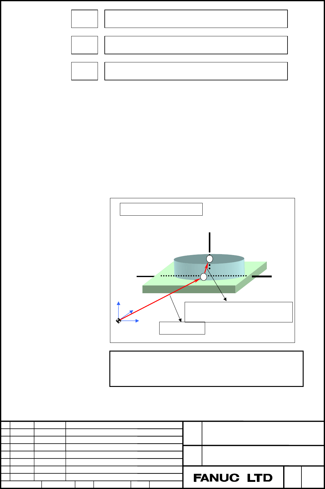
Intersection offset vector between the first and second rotation axes of the
table (X-axis of the basic three axes)
19704
Intersection offset vector between the first and second rotation axes of the
table (Y-axis of the basic three axes)
19705
Intersection offset vector between the first and second rotation axes of the
table (Z-axis of the basic three axes)
[Input type] Parameter input
[Data type] Real path
[Unit of data] mm, inch (machine unit)
[Minimum unit of data] Depend on the increment system of the applied axis
[Valid data range] 9 digit of minimum unit of data (refer to standard parameter setting table
(A))
(When the increment system is IS-B, -999999.999 to +999999.999)
Set these parameters when the first rotation axis and second rotation axis of
the table do not intersect. These parameters are valid when parameter No.
19680 is set to 12. When the rotation axes for controlling the table are all
at 0 degrees, the vector from point A to point B on the second rotation axis
of the table is set as the intersection offset vector in the machine coordinate
system.
When table rotary axes do not intersect
Zm
Ym
Xm
Second rotary axis of table
First rotary axis o
f
table
Rotary table position
Intersection offset vector between first and second rotary
axes of table
B
A
NOTE
As point B, set a position that is easy to measure
on the second rotary axis of the table.
Set a radius value.
Contents Summary of Series 30i-MODEL A, Tool center point control for 5-axis machining Additional Manual
- Page 1TECHNICAL REPORT NO. TMN 04/020E Date :Mar .30, 2004 General Manager of Software Laboratory FANUC Series 30i-A Newly additional functions 1. Communicate this report to: Your information only GE Fanuc-N, GE Fanuc-E FANUC Robotics MILACRON Machine tool builder Sales agency End user 2. Summary for Sale
- Page 2FANUC Series30i –A newly additional functions Drawing number Functions 1 A-79227E External Data Input 2 A-79226E One Touch Macro call 3 A-79196E Temporary absolute coordinate setting 4 A-79354E System alarm 5 A-79349E Touch Panel Control 6 A-79253E Distance coded linear scale interface 7 A-79364E Li
- Page 3FANUC Series 30i-MODEL A Tool center point control for 5-axis machining Specifications FANUC Series 30i-MODEL A Title Tool center point control for 5-axis machining Draw A-79348E No. Ed. Date Design Description 1/88 page Date Jan.16.’04 Design. Apprv.
- Page 4Table of contents OVERVIEW .................................................................................................................................................................3 FORMAT .......................................................................................................
- Page 51.1 TOOL CENTER POINT CONTROL FOR 5-AXIS MACHINING Overview On a 5-axis machine having two rotary axes that turn a tool or table, this function performs tool length compensation constantly, even in the middle of a block, and exerts control so that the tool center point moves along the specified path
- Page 6A Y' Z' B X' Y' Z' X' Y' Z' X' Tool center point path Fig. 1.1 (b) Path of the tool center point FANUC Series 30i-MODEL A Title Tool center point control for 5-axis machining Draw A-79348E No. Ed. Date Design Description 4/88 page Date Jan.16.’04 Design. Apprv.
- Page 7When a coordinate system fixed on the table is used as the programming coordinate system, programming can be performed without worrying about the rotation of the table because the programming coordinate system does not move with respect to the table, although the position and direction of the workpi
- Page 8Example) Machine configuration: The A-axis is the rotation axis for controlling the tool. The B-axis is the rotation axis for controlling the table. Program: Created using the programming coordinate system. A Specified Workpiece coordinate start point system used when tool center point control start
- Page 9<1> Tool rotation type machine Z C B X Y <2> Table rotation type machine Z X Y C B <3> Mixed type machine Z B X C Y Fig. 1.1 (d) Three types of 5-axis machine Even if the rotary axis that controls the tool does not intersect the one that controls the table, this function can still be used. FANUC Ser
- Page 10There are two types, as described below, one of which is used depending on how the direction of the tool axis is specified. (1) Type 1 The block end point of the rotary axes is specified (e.g. A, B, C). The CNC performs tool length compensation by the specified amount in the tool axis direction that
- Page 11- Positioning and linear interpolation for tool center point control (type 2) G43.5 IP_ H_ Q_ ; Starts tool center point control (type 2). IP_ I_ J_ K_ ; : IP : In the case of an absolute programming, the coordinate value of the end point of the tool tip movement In the case of an incremental progra
- Page 12- Circular interpolation for tool center point control (type 1) G43.4 IP_ H_ ; Starts tool center point control (type 1). G02 I J K G17 IP α β F ; G03 R G02 I J K G18 IP α β F ; G03 R G02 I J K G19 IP α β F ; G03 R : G17 : X-Y plane of the table coordinate system G18 : Z-X plane of the table coordin
- Page 13- Circular interpolation for tool center point control (type 2) G43.5 IP_ H_ Q_ ; Starts tool center point control (type 2). G02 G17 IP I J K R F ; G03 G02 G18 IP I J K R F ; G03 G02 G19 IP I J K R F ; G03 : G17 : X-Y plane of the table coordinate system G18 : Z-X plane of the table coordinate syste
- Page 14CAUTION 1 Only arc radius R can be specified. (The distance from the start point to the center of the arc cannot be specified using I, J, and K.) 2 A round circle (the start point and end point are the same) cannot be specified. 3 Any command that does not move the tool center point with respect to
- Page 15- Helical interpolation for tool center point control (type 1) G43.4 IP_ H ; Starts tool center point control (type 1). G02 I J K G17 IP α β γ F ; G03 R G02 I J K G18 IP α β γ F ; G03 R G02 I J K G19 IP α β γ F ; G03 R : G17 : X-Y plane of the table coordinate system G18 : Z-X plane of the table coo
- Page 16Because the specified speed is usually the speed in the tangent direction of the arc, the speed of the linear axis, when seen from the table coordinate Length of the linear axis system, is: F × . Length of the arc Depending on parameter HTG (No.1403#5), the specified speed varies as shown in the fol
- Page 17- Helical interpolation for tool center point control (type 2) G43.5 IP_ H_ Q_; Starts tool center point control (type G02 2). G17 IP I J K R γ F ; G03 G02 G18 IP I J K R γ F ; G03 G02 G19 IP I J K R γ F ; G03 : G17 : X-Y plane of the table coordinate system G18 : Z-X plane of the table coordinate s
- Page 18Movement to the position specified by the G43.5 block does not constitute tool center point control. Only tool length compensation is performed. Because the specified speed is the speed in the tangent direction of the arc, the speed of the linear axis, when seen from the table coordinate system, is:
- Page 19- Tool center point control cancellation command G49 IP_ α_ β_ ; Cancels tool center point control. IP : In the case of an absolute programming, the coordinate value of the end point of the tool control point movement In the case of an incremental programming, the amount of the tool control point mo
- Page 20- Inclination angle of the tool In the case of tool center point control of type 2, the inclination angle of the tool can be specified using address Q of G43.5. The inclination angle of the tool represents how inclined the tool direction is toward the proceeding direction with respect to the directi
- Page 21Explanation - When a coordinate system fixed on the table is used as the programming coordinate system The programming coordinate system is used for tool center point control. When the G43.4 or G43.5 command is specified with parameter WKP (No.19696#5) set to 0, the workpiece coordinate system that
- Page 22- When the workpiece coordinate system is used as the programming coordinate system When the G43.4 command is specified with parameter WKP (No.19696#5) set to 1, the workpiece coordinate system that is in use at that point of time becomes the programming coordinate system. In this case, the programm
- Page 23- Notes on performing circular interpolation and helical interpolation when using the workpiece coordinate system as the programming coordinate system • The start point, end point, and center of an arc change as the table rotation axis rotates. • I, J, K commands the vector of the block start point
- Page 24When the G17 (X-Y plane) command is executed After the G43.4 command, the X-Y plane is selected using the G17 command and circular interpolation is performed by rotating the C-axis (table rotation axis) (including those cases where the C-axis moves before the G43.4 command). → This case corresponds
- Page 25• In the case of a table rotation type machine Descriptions are based on the following machine configuration. A table rotation type machine can be considered equivalent to a mixed type machine if any of its two table rotation axes does not move. Z Y Workpiece coordinate system X A C When the G17 (X-
- Page 26The master axis (A-axis) moves before the G43.4 command and, after the G43.4 command, circular interpolation is performed using the G17 (X-Y plane) command by rotating the C-axis, or the C-axis is rotated during circular interpolation. → Alarm (violation of <2>) Example) : G01 A90.; G43.4 H1 ; G01 C
- Page 27When the G18 (Z-X plane) command is executed The G43.4 command is executed after moving the A- and C-axes, and circular interpolation is performed using the G18 (Z-X plane) command without moving any rotary axis. → This case corresponds to <2> and allows circular interpolation. Example) : G01 A90. C
- Page 28CAUTION The option for AI contour control function I or AI contour control function II is needed in tool center point control. And be sure to specify the following parameters: (1) Parameter LRP (No.1401#1=1)=1: Linear rapid traverse (2) Parameter FRP (No.19501#5=1)=1: Acceleration/deceleration befor
- Page 29- Tool behavior at startup and cancellation When tool center point control is started (G43.4/G43.5) or canceled (G49), the tool moves by a tool offset value. Compensation vector calculation is performed only at the end of a block. - Current position display during tool center point control During to
- Page 30- Angle of the rotary axis for type 2 (when the movement range is not specified) When the direction of the tool is specified by I, J, K, Q for type 2, more than two pairs of "computed angles" of the rotary axes usually exist. The "computed angle" is the candidate angle at which the rotary axis is to
- Page 31The process of judging whether the moving angle is smaller or larger as the output judgement condition is called "movement judgement." When parameter PRI (No.19608#5) is 1, the movement judgements for the first rotary axis and second rotary axis are made in reverse order. The "movement judgement" pr
- Page 32When the PA angle is (*1): The output angle is: (A θ2 - 360 × (N + 1) degrees; B φ2 degrees). Namely, θ2 - 360 × (N + 1) degrees is adopted that is nearer to the computed angle of A, and φ2, which is the same group as θ2, is adopted as the computed angle of B. When the PA angle is (*2): The output a
- Page 33The "output angle" is explained below using a tool rotation type machine as an example. This example illustrates a machine having a "BC type tool axis Z." Z C-axis: 1st rotation axis (master) B-axis: 2nd rotation axis ( ) Y X Fig. 1.1 (h) BC type tool axis Z The following two pairs of "computed basi
- Page 34<4> When the current rotary axis angles are (B 180 degrees; C 90 degrees) The "output angles" are (B 270 degrees; C 0 degree). Since the two candidates are equally near to the current position (90 degrees) of the C-axis that is the master axis, a judgment is made based on the current position of the
- Page 35- Angle of the rotary axis for type 2 (when the movement range is specified) If the upper and lower limits of the movement range of the rotary axis is specified using parameters No.19741 to No.19744, the rotary axis will move only within the specified range when the direction is specified using I, J
- Page 36When parameter PRI (No.19608#5) is 1, the movement judgements for the first rotary axis and second rotary axis are made in reverse order. CAUTION 1 If the lower limit of the movement range is larger than the upper limit, alarm PS5459 occurs when G43.5 is specified. 2 If no "computed angle" is found
- Page 37• Computed angle A θ2 + 360 × (N - 1) θ1 + 360 × N θ2 + 360 × N θ1 + 360 × (N + 1) 360 × N degrees 360 × (N + 1) degrees Current position A Movement range A "Computed angle of rotary axis A and its current position and movement range" • Computed angle B φ1 + 360 × (N - 1) φ2 + 360 × N φ1 + 360 × N φ
- Page 38Operation examples - In the case of a tool rotation type machine Explanations are given below assuming a machine configuration in which a tool rotation axis that turns around the Y-axis is located beneath another tool rotation axis that turns around the Z-axis. (See Fig. 1.1 (j).) If linear interpol
- Page 39C B Z' Y' X' Z' Y' X' Z' Y' X' Control point path (of the machine coordinate system) Tool center point path (of the programming coordinate system) Fig. 1.1 (j) Example for a tool rotation type machine FANUC Series 30i-MODEL A Title Tool center point control for 5-axis machining Draw A-79348E No. Ed.
- Page 40- In the case of a table rotation type machine Explanations are given below assuming a machine configuration (trunnion) in which a rotation table that turns around the Y-axis is located above another table rotation axis that turns around the X-axis. (See Fig. 1.1 (k).) If linear interpolation is spe
- Page 41For type 2 (when the coordinate system fixed on the table is used as the programming coordinate system (only when parameter WKP (No.19696#5) is set to 0)): O200 (Sample Program2) ; N1 G00 G90 A0 B0 ; N2 G55 ; Prepares the programming coordinate system. N3 G43.5 H01 ; Starts tool center point control
- Page 42Tool center point path taken when the programming coordinate system does not move A Y' Y Z' Z" B X' X Y Z' X Y X Z" Z' Y' X' Y Z' X Y X Z" Z' Y' X' Y Z' X Control point path (of the machine coordinate system) Tool center point path seen from the table-fixed coordinate system Fig. 1.1 (k) Example for
- Page 43- In the case of a mixed type machine Explanations are given below assuming a mixed type machine configuration that has one table rotation axis (which turns around the X-axis) and one tool rotation axis (which turns around the Y-axis). (See Fig. 1.1 (l).) If linear interpolation is specified for the
- Page 44For type 2 (when the coordinate system fixed on the table is used as the programming coordinate system (only when parameter WKP (No.19696#5) is set to 0)): O300 (Sample Program3) ; N1 G00 G90 A0 B0 ; N2 G55 ; Prepares the programming coordinate system. N3 G43.5 H01 ; Starts tool center point control
- Page 45B Tool center point path taken when the programming coordinate system does not move Z' Z" Y' Y X' X Z' A Y' X' Z" Z' Y Y' X X' Z' Y' X' Z" Z' Y Y' X Z' X' Y' Control point path (of the X' machine coordinate system) Tool center point path seen from the table-fixed coordinate system Fig. 1.1 (l) Examp
- Page 46- When linear interpolation is performed during tool center point control Examples are given below in which each 100-mm-long side of an equilateral triangle is cut at B-axis angles of 0, 30 to 60, and 60 degrees, respectively. Example) When type 1 is selected and the table-fixed coordinate system is
- Page 47When type 1 is selected and the workpiece coordinate system is used as the programming coordinate system (Note that the values of N60 to N90 are different from those specified in the preceding example.): O400 (Sample Program4) ; N10 G55 ; Prepares the programming coordinate system. N20 G90 X50.0 Y-7
- Page 48When type 2 is selected and the table-fixed coordinate system is used as the programming coordinate system: O400 (Sample Program4) ; N10 G55 ; Prepares the programming coordinate system. N20 G90 X50.0 Y-70.0 Z300.0 B0 C0 ; Moves to the initial position. N30 G01 G43.5 H01 Z20.0 F500. ; Starts tool ce
- Page 49The following figure illustrates the position of the workpiece, as well as the position of the tool head (relative to the workpiece), as seen from the table-fixed programming coordinate system in the +Z direction. • Behavior as seen from the table-fixed programming coordinate system (X 28.868, Y -50
- Page 50• Detailed diagram of each block (B 0) Behavior of the control point (machine coordinate value) (B 30.0) (B 30.0) X' X" (C 0) Behavior of the tool Y' center point Y" C-axis rotates, with C B-axis rotates, with (B 45.0) being 120 degrees. B being 45 degrees. N60 block X" Y' (C 120.0) (B 30.0) Y" X' (
- Page 51C-axis rotates, with C (B 60.0) being 240 degrees. (B 60.0) N80 block X" (C 240.0) Y" X' Y' (C 120.0) (B 60.0) (B 60.0) N90 block X" (C 240.0) Y" Y' X' (B 0) (C-axis rotates, with C being 360 degrees.) N100 block (C 360.0) X' X" Y' Y" Detailed diagram of each block (2) FANUC Series 30i-MODEL A Title
- Page 52- When circular interpolation is performed during tool center point control In this example, one of the three sides of an equilateral triangle, each being 100 mm long side, is specified as a straight line and the other two are specified as arcs, and each side is cut at B-axis angles of -60, -45 to -
- Page 53Center of the B-axis rotation X G54 workpiece Tool center coordinate system point C-axis Z B-axis Y X-axis Center of the C- axis rotation Z-axis Y-axis Machine configuration for the circular interpolation example The following figure illustrates the relative positional relationship between the workp
- Page 54Behavior of the control point (machine B -90 coordinate system) [Up to N031] [N032] B -45 B -60 X B -60 Behavior of the tool Y center point C 90 Y X B -30 Apparent head path B -30 B -30 [N033] [N034] Head path relative to the workpiece C 150 Y C 210 Y B -45 X X Apparent head path [N041 and later] [N
- Page 55Limitation - Manual intervention When manual intervention is made for a rotation axis while the manual absolute switch is off, the compensation vector is calculated using the position present before the manual intervention. Example: When a manual intervention of 1.0 degree is made for the C-axis whi
- Page 56- Cutter compensation for 5-axis machining When tool center point control is exercised together with cutter compensation for 5-axis machining on a machine of mixed type or table rotation type, specify a value in the workpiece coordinate system by setting the parameter WKP (No. 19696) to 1. In that c
- Page 57- Programmable mirror image Note the following points when making a programmable mirror image: • In the case of tool center point control of type 1 Mirroring the linear axis alone does not create a mirror image for the rotary axis. To make the direction of the tool symmetrical, it is necessary to ma
- Page 58• Figure copy (G72.1/G72.2) • Absolute programming (G90) • Incremental programming (G91) M • Tool offset increase (G45) • Tool offset decrease (G46) • Tool offset double increase (G47) • Tool offset double decrease (G48) - Modal G codes which can be valid when tool center point control is specified
- Page 59- Command for any axis not related to tool center point control Command for any axis not related to tool center point control can not be specified. If such a command is specified, alarm PS5421 occurs. - Linear axes for tool center point control The basic three axes specified in the parameter No.1022
- Page 60About parameters (1) Machine configuration When parameters are set, it is important to determine the target machine configuration for parameter setting. The following explains machine configuration. - Master and slave When there are two rotation axes for controlling the orientation of a tool or two
- Page 61- When the rotation axes of the table do not intersect Explained below is a mechanism in which the table rotation centers do not intersect. In the mechanism shown in the following example, the master and slave do not intersect each other. (Fig. 1.1 (n)) When both the master and slave are at 0 degree
- Page 62- When the first rotation axis of the tool and the tool axis do not intersect Explained below is a mechanism in which the tool axis (spindle rotation center axis) and the first rotation axis of the tool do not intersect. When both the master and slave are at 0 degrees, a vector from a point at a dis
- Page 63- Tool length offset value and setting in parameter No. 19666 A sum of the tool length offset value (to be set on the offset setting screen) and the setting in parameter No. 19666 (including the positive or negative sign) is assumed to be the distance between the tool center point and controlled poi
- Page 64CAUTION In a machine having a rotating tool, if the intersection offset vector between the tool axis and the tool rotation axis (parameter Nos. 19709 to 19714) is not 0, the point indicated as the controlled point in the above figure is not the controlled point but is the start point of the intersec
- Page 65(2) Examples of setting parameters There are many parameters related to this function. Therefore, it is recommended that parameters for a target machine be set based on some examples. Those examples are given below. <1> Example of setting parameters for a tool rotation type machine Shown below is an
- Page 66Parameter Setting Description No. example 19665#4 0 Automatic calculation for controlled-point shifting 19665#5 0 Controlled-point shift 19666 2.0 Tool holder offset value X0 19667 Y0 Controlled-point shift vector Z0 19680 2 Mechanical unit type 19681 6(C) Controlled axis number for the first rotati
- Page 67<2> Example of setting parameters for a table rotation type machine Shown below is an example of setting parameters for a table rotation type machine. Rotation axis A is a table rotation axis (master) on the X-axis. Rotation axis B is a table rotation axis (slave) on the Y-axis. Table rotation type
- Page 68Parameter Setting Description No. example 19665#4 0 Automatic calculation for controlled-point shifting 19665#5 0 Controlled-point shift 19666 2.0 Tool holder offset value X0.0 19667 Y0.0 Controlled-point shift vector Z0.0 19680 12 Mechanical unit type 19681 4(A) Controlled axis number for the first
- Page 69<3> Example of setting parameters for a mixed-type machine In the machine explained in this example, the first aixs is X, the second axis is Y, the third axis is Z, the fourth axis is A, the fifth axis is B, and the sixth axis is C. Shown below is an example of setting parameters for a mixed-type ma
- Page 70Parameter Setting Description No. example 19665#4 0 Automatic calculation for controlled-point shifting 19665#5 0 Controlled-point shift 19666 2.0 Tool holder offset value X0.0 19667 Y0.0 Controlled-point shift vector Z0.0 19680 21 Mechanical unit type 19681 5(B) Controlled axis number for the first
- Page 71Parameters #7 #6 #5 #4 #3 #2 #1 #0 1403 HTG [Input type] Parameter input [Data type] Bit path #5 HTG The feedrate of helical interpolation, helical involute interpolation, or three-dimensional circular interpolation is: 0: Specified as the feedrate tangent to the arc, involute curve, or three-dimens
- Page 72#7 HEL In type 2 of tool center point control for 5-axis machining, when the tool is tilted in the advancing direction by the Q command, a helical interpolation block is executed as follows: 0: The tool is tilted in a direction tangent to the arc (at the end of the block). 1: The tool is tilted in t
- Page 73NOTE When the machine has no rotation axis for rotating the tool (when parameter No. 19680 is set to 12 to specify the table rotation type), the controlled point is not shifted regardless of the setting of this parameter. 19666 Tool holder offset value [Input type] Parameter input [Data type] Real p
- Page 7419680 Mechanical unit type [Input type] Parameter input [Data type] Byte path [Valid data range] 0 to 21 Specify the type of the mechanical unit. Mechanical unit Controlled rotation PRM19680 Master and slave type axis Mechanism having no 0 rotation axis The first rotation axis is the master, Tool ro
- Page 7519681 Controlled-axis number for the first rotation axis [Input type] Parameter input [Data type] Byte path [Valid data range] 0 to Number of controlled axes in each path Set the controlled-axis number (in each path) for the first rotation axis. For a hypothetical axis (when bit 0 (IA1) of parameter
- Page 7619683 Inclination angle when the first rotation axis is an inclined axis [Input type] Parameter input [Data type] Real path [Unit of data] Degree [Minimum unit of data] The increment system of the reference axis is to be followed. [Valid data range] Nine digits of the least input increment (see stan
- Page 7719684 Rotation direction of the first rotation axis [Input type] Parameter input [Data type] Byte path [Valid data range] 0 to 1 Set the direction in which the first rotation axis rotates as a mechanical motion when a positive move command is issued. 0: Clockwise direction as viewed from the negativ
- Page 7819687 Axis direction of the second rotation axis [Input type] Parameter input [Data type] Byte path [Valid data range] 1 to 6 Specify the axis direction of the second rotation axis. 1: On X-axis 2: On Y-axis 3: On Z-axis 4: On an axis tilted a certain angle from the X-axis from the positive X-axis t
- Page 7919689 Rotation direction of the second rotation axis [Input type] Parameter input [Data type] Byte path [Valid data range] 0 to 1 Set the direction in which the second rotation axis rotates as a mechanical motion when a positive move command is issued. 0: Clockwise direction as viewed from the negat
- Page 80#7 #6 #5 #4 #3 #2 #1 #0 19696 SUP RFC WKP IA2 IA1 [Input type] Parameter input [Data type] Bit path #0 IA1 0: The first rotation axis is an ordinary rotation axis. 1: The first rotation axis is a hypothetical axis. If IA1 is 1, set 0 as the controlled-axis number for the first rotation axis (paramet
- Page 8119697 Reference tool axis direction [Input type] Parameter input [Data type] Byte path [Valid data range] 1 to 3 Set the tool axis direction in the machine coordinate system when the rotation axes for controlling the tool are all at 0 degrees. Also, set the tool axis direction in the machine coordin
- Page 8219698 Angle when the reference tool axis direction is tilted (reference angle RA) 19699 Angle when the reference tool axis direction is tilted (reference angle RB) [Input type] Parameter input [Data type] Real path [Unit of data] Degree [Minimum unit of data] Depend on the increment system of the re
- Page 8319700 Rotary table position (X-axis of the basic three axes) 19701 Rotary table position (Y-axis of the basic three axes) 19702 Rotary table position (Z-axis of the basic three axes) [Input type] Parameter input [Data type] Real path [Unit of data] mm, inch (machine unit) [Minimum unit of data] Depe
- Page 84Intersection offset vector between the first and second rotation axes of the 19703 table (X-axis of the basic three axes) Intersection offset vector between the first and second rotation axes of the 19704 table (Y-axis of the basic three axes) Intersection offset vector between the first and second
- Page 85Intersection offset vector between the tool axis and tool rotation axis (X-axis 19709 of the basic three axes) Intersection offset vector between the tool axis and tool rotation axis (Y-axis 19710 of the basic three axes) Intersection offset vector between the tool axis and tool rotation axis (Z-axi
- Page 86Intersection offset vector between the second and first rotation axes of the 19712 tool (X-axis of the basic three axes) Intersection offset vector between the second and first rotation axes of the 19713 tool (Y-axis of the basic three axes) Intersection offset vector between the second and first ro
- Page 8719741 Upper limit of the movement range of the first rotation axis [Input type] Parameter input [Data type] Real path [Unit of data] Degree [Minimum unit of data] Depend on the increment system of the reference axis [Valid data range] 9 digit of minimum unit of data (refer to standard parameter sett
- Page 8819744 Lower limit of the movement range of the second rotation axis [Input type] Parameter input [Data type] Real path [Unit of data] Degree [Minimum unit of data] Depend on the increment system of the reference axis [Valid data range] 9 digit of minimum unit of data (refer to standard parameter set
- Page 89Alarm and message No. Message Description PS5420 ILLEGAL PARAMETER IN A parameter related to tool center point control is illegal. G43.4/G43.5 - Acceleration/deceleration before interpolation is invalid. Set the parameter No.1660. - Acceleration/deceleration before interpolation for rapid traverse i
- Page 90No. Message Description PS5459 MACHINE PARAMETER - A machine configuration parameter (parameter No. INCORRECT 19665 to No.19667 or 19680 to 19714 or No.12321) is illegal. - The axis which is specified in parameter No.19681 or No.19686 is not a rotation axis. - The basic three axes are not specified