AC Servo Motor Beta is, AC Spindle Motor Beta i, Servo Amplifier Beta i Maintenance manual Page 49
Maintenance manual
B-65325EN/01 START-UP PROCEDURE FOR βi SVM 4.CONFIRMATION OF THE OPERATION
- 19 -
Setting the output period of motor current data (for the 90B0 series
only)
Output period
Parameter No. 1746 /
Bit 7 of parameter No. 2206
Velocity loop period 0 (default)
Current loop period 1
(Note 3)
NOTE
3 If the current loop period is set up as the motor
current data output period, selecting data number 0,
1, 2, or 4 disables the output of signals (such as a
velocity command) to channels. To observe the
motor current and other signals (such as a velocity
command), specify the output period as 1 ms.
4 For the servo software series 9096, the output
period of the motor current is only 1 msec. The
current loop period cannot be used for output.
⋅
⋅⋅
⋅ Setting up the check board
• Set the AXIS digit of the LED display with an axis number from 1
to 8 specified in parameter No. 1023.
• Set the DATA digit of the LED display with a data number from 5
to 6.
- Method for observing the motor current
The voltage corresponding to the motor current is output to a channel
for which 5 or 6 is set as the data number on the servo check board.
The waveform of the motor current can be observed by measuring the
voltage mentioned above with an oscilloscope.
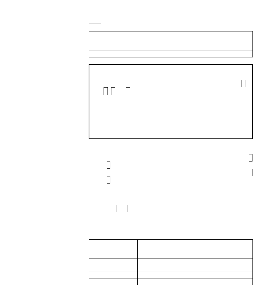
The following table lists the relationships between the observed
voltage and the motor current.
Maximum amplifier
current
SVM type
Motor current/
observed voltage
[A/V]
4A
SVM1-4i
1
20A
SVM1-20i
5
40A
SVM1-40i
10
80A
SVM1-80i
20
For the SVM1-20i, for example, the motor current is 5A (actual value
rather than effective value) if the observed voltage is 1V.
Contents Summary of AC Servo Motor Beta is, AC Spindle Motor Beta i, Servo Amplifier Beta i Maintenance manual
- Page 1FANUC AC SERVO MOTOR #*s series FANUC AC SPINDLE MOTOR #* series FANUC SERVO AMPLIF IER #* series MAINTENANCE MANUAL B-65325EN/01
- Page 2Ȧ No part of this manual may be reproduced in any form. Ȧ All specifications and designs are subject to change without notice. In this manual we have tried as much as possible to describe all the various matters. However, we cannot describe all the matters which must not be done, or which cannot be
- Page 3B-65325EN/01 SAFETY PRECAUTIONS SAFETY PRECAUTIONS The "Safety Precautions" section describes the safety precautions relating to the use of FANUC servo motors, spindle motors, and servo amplifiers (βi SVM and βi SVPM). Users of any servo motor or amplifier model are requested to read the "Safety Pre
- Page 4SAFETY PRECAUTIONS B-65325EN/01 1.1 DEFINITION OF WARNING, CAUTION, AND NOTE This manual includes safety precautions for protecting the user and preventing damage to the machine. Precautions are classified into Warning and Caution according to their bearing on safety. Also, supplementary information
- Page 5B-65325EN/01 SAFETY PRECAUTIONS 1.2 FANUC AC SERVO MOTOR βis series FANUC AC SPINDLE MOTOR βi series 1.2.1 Warning WARNING • Be safely dressed when handling a motor. Wear safety shoes or gloves when handling a motor as you may get hurt on any edge or protrusion on it or electric shocks. • Use a cran
- Page 6SAFETY PRECAUTIONS B-65325EN/01 WARNING • Do not supply the power to the motor while any terminal is exposed. A failure to observe this caution is very dangerous because you may get electric shocks if your body or any conductive stuff touches an exposed terminal. • Do not bring any dangerous stuff n
- Page 7B-65325EN/01 SAFETY PRECAUTIONS • Do not touch a regenerative discharge unit for a while (at least 30 minutes) after the power to the motor is shut off. A regenerative discharge unit may get hot when the motor is running. Do not touch the regenerative discharge unit before it gets cool enough. Other
- Page 8SAFETY PRECAUTIONS B-65325EN/01 1.2.2 Caution CAUTION • FANUC motors are designed for use with machines. Do not use them for any other purpose. If a FANUC motor is used for an unintended purpose, it may cause an unexpected symptom or trouble. If you want to use a motor for an unintended purpose, pre
- Page 9B-65325EN/01 SAFETY PRECAUTIONS 1.2.3 Note NOTE • Do not step or sit on a motor. If you step or sit on a motor, it may get deformed or broken. Do not put a motor on another unless they are in packages. • When storing a motor, put it in a dry (non-condensing) place at room temperature (0 to 40°°C). I
- Page 10SAFETY PRECAUTIONS B-65325EN/01 NOTE • Use a motor under an appropriate environmental condition. Using a motor in an adverse environment may cause a failure or trouble in it. Refer to their respective Descriptions for details of the operating and environmental conditions for motors. • Do not apply a
- Page 11B-65325EN/01 SAFETY PRECAUTIONS 1.3 FANUC SERVO AMPLIFIER βi series 1.3.1 Warnings and Cautions Relating to Mounting 1.3.1.1 Warning WARNING • Check the specification code of the amplifier. Check that the delivered amplifier is as originally ordered. • Mount a ground fault interrupter. To guard agai
- Page 12SAFETY PRECAUTIONS B-65325EN/01 WARNING • Never touch the regenerative discharge resistor or radiator directly. The surface of the radiator and regenerative discharge unit become extremely hot. Never touch them directly. An appropriate structure should also be considered. • Close the amplifier cover
- Page 13B-65325EN/01 SAFETY PRECAUTIONS 1.3.1.2 Caution CAUTION • Do not step or sit on the amplifier. Also, do not stack unpacked amplifiers on top of each other. • Use the amplifier in an appropriate environment. See the allowable ambient temperatures and other requirements, given in the corresponding Des
- Page 14SAFETY PRECAUTIONS B-65325EN/01 CAUTION • Check that the amplifier is securely mounted in the power magnetics cabinet. If any clearance is left between the power magnetics cabinet and the surface on which the amplifier is mounted, dust entering the gap may build up and prevent the normal operation o
- Page 15B-65325EN/01 SAFETY PRECAUTIONS 1.3.1.3 Note NOTE • Keep the nameplate clearly visible. • Keep the legend on the nameplate clearly visible. • After unpacking the amplifier, carefully check for any damage. • Mount the amplifier in a location where it can be easily accessed periodic inspection and dai
- Page 16SAFETY PRECAUTIONS B-65325EN/01 1.3.2 Warnings and Cautions Relating to a Pilot Run 1.3.2.1 Warning WARNING • Before turning on the power, check that the cables connected to the power magnetics cabinet and amplifier, as well as the power lines and power supply lines, are securely connected. Also, ch
- Page 17B-65325EN/01 SAFETY PRECAUTIONS • After turning on the power, check the operation of the emergency stop circuit. Press the emergency stop button to check that the motor stops immediately, and that the power being supplied to the amplifier is shut off by the magnetic contactor. • Before opening a doo
- Page 18SAFETY PRECAUTIONS B-65325EN/01 1.3.2.2 Caution CAUTION • Note whether an alarm status relative to the amplifier is displayed at power-up or during operation. If an alarm is displayed, take appropriate action as explained in this manual. If the work to be done requires that the door of the power mag
- Page 19B-65325EN/01 SAFETY PRECAUTIONS 1.3.3 Warnings and Cautions Relating to Maintenance 1.3.3.1 Warning WARNING • Read this manual carefully and ensure that you are totally familiar with its contents. This manual describes daily maintenance and the procedures to be followed in the event of an alarm bein
- Page 20SAFETY PRECAUTIONS B-65325EN/01 WARNING • Notes on replacing the battery of the absolute Pulsecoder Replace the battery only while the power is on. If the battery is replaced while the power is turned off, the stored absolute positioning data will be lost. Some βi series servo amplifier modules have
- Page 21B-65325EN/01 SAFETY PRECAUTIONS 1.3.3.2 Caution CAUTION • Ensure that all required components are mounted. When replacing a component or PC board, check that all components, including the snubber capacitor, are correctly mounted. If the snubber capacitor is not mounted, for example, the IPM will be
- Page 22SAFETY PRECAUTIONS B-65325EN/01 1.3.3.3 Note NOTE • Ensure that the battery connector is correctly inserted. If the power is shut off while the battery connector is not connected correctly, the absolute position data for the machine will be lost. • Store the manuals in a safe place. The manuals shou
- Page 23B-65325EN/01 PREFACE PREFACE Organization of this manual This manual describes information necessary to maintain FANUC SERVO AMPLIFIER βi series products, such as a βi SVM and βi SVPM and FANUC SERVO MOTOR βis series and FANUC SPINDLE MOTOR βi series products. Parts I and II explain the start-up pro
- Page 24
- Page 25B-65325EN/01 TABLE OF CONTENTS TABLE OF CONTENTS SAFETY PRECAUTIONS .......................................................................... s-1 PREFACE.................................................................................................. p-1 I. START-UP PROCEDURE FOR βi SVM 1 OVERVIEW
- Page 26TABLE OF CONTENTS B-65325EN/01 2.2 FOR Series 16i, 18i, 20i, 21i, 0i, AND Power Mate i...................................36 2.2.1 Servo Alarm........................................................................................................... 36 3 TROUBLESHOOTING AND ACTION ...................
- Page 27B-65325EN/01 TABLE OF CONTENTS 2.1 CONFIGURATIONS ....................................................................................67 2.2 MAJOR COMPONENTS..............................................................................69 2.2.1 βi SVPM.................................................
- Page 28TABLE OF CONTENTS B-65325EN/01 4.3.6.5 Address descriptions and initial values (SVPM) ................................................94 4.3.6.6 Principles in outputting the internal data of the serial spindle............................95 4.3.6.7 Data numbers .......................................
- Page 29B-65325EN/01 TABLE OF CONTENTS 3.2.2 STATUS2 Alarm Code 5 .................................................................................... 133 3.2.3 STATUS2 Alarm Code 6 .................................................................................... 133 3.2.4 STATUS2 Alarm Code P ..........
- Page 30TABLE OF CONTENTS B-65325EN/01 3.4.21 Alarm Code 46..................................................................................................... 158 3.4.22 Alarm Code 47..................................................................................................... 159 3.4.23 Alarm Code
- Page 31I. START-UP PROCEDURE FOR βi SVM
- Page 32
- Page 33B-65325EN/01 START-UP PROCEDURE FOR βi SVM 1.OVERVIEW OVERVIEW This part describes the units and components of the FANUC servo amplifier βi series. It also explains the following information necessary to start up the servo amplifier: • Configurations • Start-up procedure • Confirmation of the operat
- Page 342.CONFIGURATIONS START-UP PROCEDURE FOR βi SVM B-65325EN/01 CONFIGURATIONS -4-
- Page 35B-65325EN/01 START-UP PROCEDURE FOR βi SVM 2.CONFIGURATIONS 2.1 CONFIGURATIONS The FANUC servo amplifier βi series servo amplifier module SVM consists of the units and components listed below: (1) Servo amplifier module (SVM) (basic) (2) AC line filter (basic) (3) Connectors (for connecting cables)
- Page 362.CONFIGURATIONS START-UP PROCEDURE FOR βi SVM B-65325EN/01 Constituent (example) Control power supply 24VDC ± 10% βi series βi series SVM SVM 3φ 200 to 240 VAC Circuit Magnetic AC line breker contactor filter or 1φ 220 to 240 VAC Servo Servo (4A or 20A models motor motor only) : Basic : Option : Un
- Page 37B-65325EN/01 START-UP PROCEDURE FOR βi SVM 2.CONFIGURATIONS 2.2 MAJOR COMPONENTS 2.2.1 Servo Amplifier Modules (1) Servo amplifier module (SVM1) Wiring board Printed circuit board Model Order specification Unit specification specification specification SVM1-4i A06B-6130-H001 A06B-6130-C001 A20B-2101
- Page 383.START-UP PROCEDURE START-UP PROCEDURE FOR βi SVM B-65325EN/01 START-UP PROCEDURE -8-
- Page 39B-65325EN/01 START-UP PROCEDURE FOR βi SVM 3.START-UP PROCEDURE 3.1 START-UP PROCEDURE (OVERVIEW) Make sure that the specifications of the CNC, servo motors, servo amplifiers, and other units you received are exactly what you ordered, and these units are connected correctly. Then, turn on the power.
- Page 403.START-UP PROCEDURE START-UP PROCEDURE FOR βi SVM B-65325EN/01 3.2 CONNECTING THE POWER 3.2.1 Checking the Voltage and Capacity of the Power Before connecting the power, you should measure the AC power voltage. Table 3.2.1(a) Action for the AC power (200-V input type) Permissible voltage Nominal Ac
- Page 41B-65325EN/01 START-UP PROCEDURE FOR βi SVM 3.START-UP PROCEDURE 3.3 INITIALIZING PARAMETERS (SWITCHES AND DUMMY CONNECTORS) SVM1-4i, SVM1-20i • When no regenerative resistor is used Connect connector CXA20 by using a dummy connector. See FANUC SERVO AMPLIFIER βi series DESCRIPTIONS B-65322EN. SVM1-4
- Page 423.START-UP PROCEDURE START-UP PROCEDURE FOR βi SVM B-65325EN/01 3.4 INITIALIZING SETTINGS (1) Servo amplifier module For the initialization of servo parameters, refer to the following manual: FANUC AC SERVO MOTOR αis/αi/βis series Parameter Manual (B-65270EN) - 12 -
- Page 43B-65325EN/01 START-UP PROCEDURE FOR βi SVM 4.CONFIRMATION OF THE OPERATION CONFIRMATION OF THE OPERATION - 13 -
- Page 444.CONFIRMATION OF THE OPERATION START-UP PROCEDURE FOR βi SVM B-65325EN/01 4.1 SERVO AMPLIFIER MODULE 4.1.1 Check Procedure 1. Turn on power. ALM LED goes on. See servo adjustment screen of host (NC, Power Mate, and so on). 2. ALM LED does not go on. 3. Check NC parameters, then release emergency st
- Page 45B-65325EN/01 START-UP PROCEDURE FOR βi SVM 4.CONFIRMATION OF THE OPERATION Yamanashi 401-0597 JAPAN made in JAPAN ALM LED (yellow) LINK LED (green) POWER LED (green) Yamanashi 401-0597 JAPAN ALM LED (yellow) LINK LED (green) POWER LED (green) - 15 -
- Page 464.CONFIRMATION OF THE OPERATION START-UP PROCEDURE FOR βi SVM B-65325EN/01 4.1.2 VRDY-OFF Alarm Indicated on the CNC Screen When the VRDY-OFF alarm is indicated on the CNC, check the items listed below. In addition, VRDY-OFF can occur also for reasons other than listed below. If the following items
- Page 47B-65325EN/01 START-UP PROCEDURE FOR βi SVM 4.CONFIRMATION OF THE OPERATION 4.1.3 Method for Observing Motor Current This subsection explains how to observe the current that flows through the servo motor. Method of using the SERVO GUIDE Refer to online help for explanations about how to connect to an
- Page 484.CONFIRMATION OF THE OPERATION START-UP PROCEDURE FOR βi SVM B-65325EN/01 - Display Select the XTYT mode from the graph window mode (M) menu to display waveforms. Method of using the servo check board For details on how to connect and use the servo check board, refer to the following manual: FANUC
- Page 49B-65325EN/01 START-UP PROCEDURE FOR βi SVM 4.CONFIRMATION OF THE OPERATION Setting the output period of motor current data (for the 90B0 series only) Parameter No. 1746 / Output period Bit 7 of parameter No. 2206 Velocity loop period 0 (default) (Note 3) Current loop period 1 NOTE 3 If the current l
- Page 505.PERIODIC MAINTENANCE OF SERVO AMPLIFIER START-UP PROCEDURE FOR βi SVM B-65325EN/01 PERIODIC MAINTENANCE OF SERVO AMPLIFIER - 20 -
- Page 51B-65325EN/01 START-UP PROCEDURE FOR βi SVM 5.PERIODIC MAINTENANCE OF SERVO AMPLIFIER 5.1 BATTERY FOR THE ABSOLUTE PULSECODER The battery unit for the absolute Pulsecoder can be connected using [Connection scheme 1] and [Connection scheme 2] explained below. [Connection scheme 1] Supplying power from
- Page 525.PERIODIC MAINTENANCE OF SERVO AMPLIFIER START-UP PROCEDURE FOR βi SVM B-65325EN/01 WARNING 1 Do not connect more than one battery to the same BAT (B3) line. If the output voltage is different between the batteries, they may be short-circuited, resulting in the batteries becoming very hot. 2 Instal
- Page 53B-65325EN/01 START-UP PROCEDURE FOR βi SVM 5.PERIODIC MAINTENANCE OF SERVO AMPLIFIER [Connection scheme 2] Incorporating each SVM with batteries SVM SVM Battery case A06B-6093-K002 Battery A06B-6093-K001 CX5X CX5X Battery case A06B-6093-K002 Battery A06B-6093-K001 • If a low battery voltage or a bat
- Page 545.PERIODIC MAINTENANCE OF SERVO AMPLIFIER START-UP PROCEDURE FOR βi SVM B-65325EN/01 • The built-in batteries are not commercially available. They must be purchased from FANUC. So, FANUC recommends that you keep spares. WARNING 1 When using the built-in batteries (A06B-6073-K001), do not connect the
- Page 55B-65325EN/01 START-UP PROCEDURE FOR βi SVM 5.PERIODIC MAINTENANCE OF SERVO AMPLIFIER ⋅ SVM1-40i, SVM1-80i (1) Install the battery in the SVM. (2) Install the battery cover. (3) Attach the battery connector to CX5X of the SVM. SVM Inserting direction Cable side Red: +6 V Connector Black: 0 V Battery
- Page 565.PERIODIC MAINTENANCE OF SERVO AMPLIFIER START-UP PROCEDURE FOR βi SVM B-65325EN/01 [Caution No. 1 for battery replacement] The Pulsecoder of the β series servo motors and some of the βiS series servo motors (β0.2/5000iS to β0.3/5000iS) does not include a backup capacitor as standard. To keep the a
- Page 57B-65325EN/01 START-UP PROCEDURE FOR βi SVM 5.PERIODIC MAINTENANCE OF SERVO AMPLIFIER [Caution No. 2 for battery replacement] If an excessive strain is applied to a connector when it is inserted or removed, a poor contact may result. When inserting and removing the battery connector, therefore, be ca
- Page 585.PERIODIC MAINTENANCE OF SERVO AMPLIFIER START-UP PROCEDURE FOR βi SVM B-65325EN/01 (2) Detaching the connector Hold both the sides of the cable insulator and the cable, and pull them horizontally. <1> Pull out the cable side while raising it slightly. <2> 10 degrees or less Here, the angle of the
- Page 59B-65325EN/01 START-UP PROCEDURE FOR βi SVM 5.PERIODIC MAINTENANCE OF SERVO AMPLIFIER 5.2 PERIODIC MAINTENANCE OF SERVO AMPLIFIER To use the servo amplifier for a long time and keep its high performance and reliability, you should perform maintenance and inspection on it routinely. Inspection Inspect
- Page 605.PERIODIC MAINTENANCE OF SERVO AMPLIFIER START-UP PROCEDURE FOR βi SVM B-65325EN/01 Specification number of fan unit - SVM Fan for circulating the inside air Fan for cooling external heat sink fins SVM name Fan unit (*1) Fan motor Fan unit (*1) Fan motor SVM1-20i A06B-6134-K003 A90L-0001-0423#50 -
- Page 61II. TROUBLESHOOTING FOR βi SVM
- Page 62
- Page 63B-65325EN/01 TROUBLESHOOTING FOR βi SVM 1.OVERVIEW OVERVIEW This part describes the troubleshooting procedure. Read the section related to your current trouble to locate it and take an appropriate action. First, check the alarm number (indicated by the CNC) and the SVM indication in Chapter 2 to fin
- Page 642.ALARM NUMBERS AND BRIEF DESCRIPTIONS TROUBLESHOOTING FOR βi SVM B-65325EN/01 ALARM NUMBERS AND BRIEF DESCRIPTIONS - 34 -
- Page 65B-65325EN/01 TROUBLESHOOTING FOR βi SVM 2.ALARM NUMBERS AND BRIEF DESCRIPTIONS 2.1 FOR Series 15i 2.1.1 Servo Alarm Alarm No. Description Remark SV0027 Invalid digital servo parameter setting 3.2.6 SV0361 Pulsecoder phase error (built-in) 3.2.7 (1) SV0364 Soft phase alarm (built-in) 3.2.7 (1) SV0365
- Page 662.ALARM NUMBERS AND BRIEF DESCRIPTIONS TROUBLESHOOTING FOR βi SVM B-65325EN/01 2.2 FOR Series 16i, 18i, 20i, 21i, 0i, AND Power Mate i 2.2.1 Servo Alarm Alarm No. Description Remark 361 Pulsecoder phase error (built-in) 3.2.7 (1) 364 Soft phase alarm (built-in) 3.2.7 (1) 365 LED error (built-in) 3.2
- Page 67B-65325EN/01 TROUBLESHOOTING FOR βi SVM 3.TROUBLESHOOTING AND ACTION TROUBLESHOOTING AND ACTION - 37 -
- Page 683.TROUBLESHOOTING AND ACTION TROUBLESHOOTING FOR βi SVM B-65325EN/01 3.1 SERVO AMPLIFIER MODULE The following table lists alarms related to the servo amplifier module. See this table and the CNC alarm code indicated in Chapter 2, "ALARM NUMBERS AND BRIEF DESCRIPTIONS". LED Alarm Major cause Referenc
- Page 69B-65325EN/01 TROUBLESHOOTING FOR βi SVM 3.TROUBLESHOOTING AND ACTION 3.1.1 Converter: DC Link Undervoltage (1) Meaning The voltage at the DC link of the converter is low. (2) Cause and troubleshooting (a) A small power dip has occurred. → Check the power supply. (b) Low input power supply voltage →
- Page 703.TROUBLESHOOTING AND ACTION TROUBLESHOOTING FOR βi SVM B-65325EN/01 For SVM1-40i and SVM1-80i • When the built-in regenerative resistor is used (a) Connect CXA20 and CZ6 by using a dummy connector. (b) The average regenerative power may be high. Decrease the frequency of acceleration/deceleration,
- Page 71B-65325EN/01 TROUBLESHOOTING FOR βi SVM 3.TROUBLESHOOTING AND ACTION 3.1.6 Inverter: Cooling Fan Stopped of the Radiator (1) Meaning Inverter: cooling fan stopped of the radiator (2) Cause and troubleshooting (a) Check whether there is any foreign material in the fan. (b) Be sure to push the facepla
- Page 723.TROUBLESHOOTING AND ACTION TROUBLESHOOTING FOR βi SVM B-65325EN/01 3.1.8 Inverter: IPM Alarm (OH) (1) Meaning Inverter: IPM alarm (OH) (2) Cause and troubleshooting (a) Be sure to push the faceplate (control printed-circuit board) as far as it will go. (b) Check that the heat sink cooling fan is r
- Page 73B-65325EN/01 TROUBLESHOOTING FOR βi SVM 3.TROUBLESHOOTING AND ACTION 3.1.9 Inverter: Motor Current Alarm (1) Meaning Inverter: DC link current alarm (2) Cause and troubleshooting (a) Checking the servo parameters Referring to "FANUC AC SERVO MOTOR αis/αi/βis series Parameter Manual (B-65270EN)," che
- Page 743.TROUBLESHOOTING AND ACTION TROUBLESHOOTING FOR βi SVM B-65325EN/01 3.1.10 Inverter: FSSB Communication Error (1) Meaning Inverter: FSSB communication error (2) Cause and troubleshooting (a) Replace the optical cable (COP10A) of the SVM that is nearest to the CNC among the amplifiers on which the A
- Page 75B-65325EN/01 TROUBLESHOOTING FOR βi SVM 3.TROUBLESHOOTING AND ACTION 3.2 SERVO SOFTWARE If a servo alarm is issued, an alarm message is output, and details of the alarm are also displayed on the servo adjustment screen or the diagnosis screen. Using the alarm identification table given in this secti
- Page 763.TROUBLESHOOTING AND ACTION TROUBLESHOOTING FOR βi SVM B-65325EN/01 Alarm detail information <1> <6> <2> <7> <3> <8> <4> <9> <5> Fig. 3.2.1(b) Series 15i servo alarm screen The table below indicates the names of the alarm bits. Table 3.2.1 List of alarm bit names #7 #6 #5 #4 #3 #2 #1 #0 <1> Alarm 1
- Page 77B-65325EN/01 TROUBLESHOOTING FOR βi SVM 3.TROUBLESHOOTING AND ACTION 3.2.2 Diagnosis Screen The alarm items of the servo adjustment screen correspond to the diagnosis screen numbers indicated in the table below. Table 3.2.2 Correspondence between the servo adjustment screen and diagnosis screen Alar
- Page 783.TROUBLESHOOTING AND ACTION TROUBLESHOOTING FOR βi SVM B-65325EN/01 3.2.3 Overload Alarm (Soft Thermal, OVC) (Alarm identification method) #7 #6 #5 #4 #3 #2 #1 #0 <1> Alarm 1 OVL LVA OVC HCA HVA DCA FBA OFA (Action) (1) Make sure that the motor is not vibrating. Þ If a motor vibrates, the current f
- Page 79B-65325EN/01 TROUBLESHOOTING FOR βi SVM 3.TROUBLESHOOTING AND ACTION 3.2.4 Feedback Disconnected Alarm (Alarm identification method) #7 #6 #5 #4 #3 #2 #1 #0 <1> Alarm 1 OVL LVA OVC HCA HVA DCA FBA OFA <2> Alarm 2 ALD EXP <6> Alarm 6 SFA FBA ALD EXP SFA Alarm description Action 1 1 1 0 Hard disconnec
- Page 803.TROUBLESHOOTING AND ACTION TROUBLESHOOTING FOR βi SVM B-65325EN/01 3.2.5 Overheat Alarm (Alarm identification method) #7 #6 #5 #4 #3 #2 #1 #0 <1> Alarm 1 OVL LVA OVC HCA HVA DCA FBA OFA <2> Alarm 2 ALD EXP OVL ALD EXP Alarm description Action 1 1 0 Motor overheat 1 1 0 0 Amplifier overheat 1 (Acti
- Page 81B-65325EN/01 TROUBLESHOOTING FOR βi SVM 3.TROUBLESHOOTING AND ACTION 3.2.7 Alarms Related to Pulsecoder and Separate Serial Detector (Bits for alarm identification) #7 #6 #5 #4 #3 #2 #1 #0 <1> Alarm 1 OVL LVA OVC HCA HVA DCA FBA OFA <2> Alarm 2 ALD EXP <3> Alarm 3 CSA BLA PHA RCA BZA CKA SPH <4> Ala
- Page 823.TROUBLESHOOTING AND ACTION TROUBLESHOOTING FOR βi SVM B-65325EN/01 (2) For a separate serial detector An alarm is determined from the bits of alarm 7. The table below indicates the meaning of each bit. Alarm 7 Alarm description Action OHA LDA BLA PHA CMA BZA PMA SPH 1 Soft phase alarm 2 1 Pulse er
- Page 83B-65325EN/01 TROUBLESHOOTING FOR βi SVM 3.TROUBLESHOOTING AND ACTION (3) Alarms related to serial communication An alarm is determined from the bits of alarms 4 and 8. Alarm 4 Alarm 8 Alarm description DTE CRC STB DTE CRC STB 1 1 Serial Pulsecoder communication alarm 1 1 1 Separate serial Pulsecoder
- Page 843.TROUBLESHOOTING AND ACTION TROUBLESHOOTING FOR βi SVM B-65325EN/01 3.2.8 Other Alarms (Alarm identification method) #7 #6 #5 #4 #3 #2 #1 #0 <5> Alarm 5 OFS MCC LDM PMS FAN DAL ABF OFS DAL ABF Alarm description Action 1 Feedback mismatch alarm 1 1 Excessive semi-full error alarm 2 1 Current offset
- Page 85B-65325EN/01 TROUBLESHOOTING FOR βi SVM 3.TROUBLESHOOTING AND ACTION Action 2: This alarm is issued when the difference between the motor position and separate detector position exceeds the excessive semi-full error level. Check if the conversion efficient for dual position feedback is set correctly
- Page 864.HOW TO REPLACE THE FUSES AND PRINTED CIRCUIT BOARDS TROUBLESHOOTING FOR βi SVM B-65325EN/01 HOW TO REPLACE THE FUSES AND PRINTED CIRCUIT BOARDS WARNING Before replacing fuses or printed-circuit boards, make sure that the recharge-under-way LED (red) is off. Before replacing fuses or printed circui
- Page 87B-65325EN/01 TROUBLESHOOTING FOR βi SVM 4.HOW TO REPLACE THE FUSES AND PRINTED CIRCUIT BOARDS 4.1 HOW TO REPLACE THE FUSES AND PRINTED CIRCUIT BOARDS A printed-circuit board can be removed and inserted from the front of the servo amplifier. SVM1-4i, SVM1-20i Hold the upper and lower hooks. Pull the
- Page 884.HOW TO REPLACE THE FUSES AND PRINTED CIRCUIT BOARDS TROUBLESHOOTING FOR βi SVM B-65325EN/01 SVM1-40i, SVM1-80i Hold the upper and lower hooks. Pull the printed-circuit board toward you. Printed circuit board To insert the printed-circuit board, reverse the above procedure. Ensure that the upper an
- Page 89B-65325EN/01 TROUBLESHOOTING FOR βi SVM 4.HOW TO REPLACE THE FUSES AND PRINTED CIRCUIT BOARDS 4.1.1 Ordering Number of Printed Circuit Board SVM Model Ordering number SVM1-4i to 20i A20B-2101-009* SVM1-40i to 80i A16B-3200-051* 4.1.2 Fuse Locations There is one fuse on the SVM printed-circuit board.
- Page 904.HOW TO REPLACE THE FUSES AND PRINTED CIRCUIT BOARDS TROUBLESHOOTING FOR βi SVM B-65325EN/01 4.2 HOW TO REPLACE THE FAN MOTOR 4.2.1 Internal-Fan Motor Replacement Procedure for SVM1-4i and SVM1-20i <1> Pull out the fan connector upward. <2> Push the front of the fan unit to disengage the lug. <3> D
- Page 91B-65325EN/01 TROUBLESHOOTING FOR βi SVM 4.HOW TO REPLACE THE FUSES AND PRINTED CIRCUIT BOARDS 4.2.2 Internal-Fan Motor Replacement Procedure for SVM1-40i and SVM1-80i <1> Remove the four sheet metal fixing screws and then pull out the fan unit. Holding the two lugs on the fan unit, lift the fan unit
- Page 924.HOW TO REPLACE THE FUSES AND PRINTED CIRCUIT BOARDS TROUBLESHOOTING FOR βi SVM B-65325EN/01 4.2.3 External-Fan Motor <1> Holding the two lugs on the fan unit, lift the fan unit in the direction of the arrow (upward in the figure). Four M4 screws Fan motor blow direction - 62 -
- Page 93III. START-UP PROCEDURE FOR βi SVPM
- Page 94
- Page 95B-65325EN/01 START-UP PROCEDURE FOR βi SVPM 1.OVERVIEW OVERVIEW This part describes the units and components of the FANUC servo amplifier βi series. It also explains the following information necessary to start up the amplifier: • Configurations • Start-up procedure • Confirmation of the operation •
- Page 962.CONFIGURATIONS START-UP PROCEDURE FOR βi SVPM B-65325EN/01 CONFIGURATIONS - 66 -
- Page 97B-65325EN/01 START-UP PROCEDURE FOR βi SVPM 2.CONFIGURATIONS 2.1 CONFIGURATIONS The FANUC servo amplifier βi series consists of the units and components listed below: (1) βi SVPM (basic) (2) AC reactor (basic) (3) Connectors (for connecting cables) (basic) (4) Fuses (option) (5) Power transformer (o
- Page 982.CONFIGURATIONS START-UP PROCEDURE FOR βi SVPM B-65325EN/01 Constituent (example) Fan unit Fan unit SVPM JF1 Servo Motor Pulsecoder I/F JF2 Servo Motor JF3 Servo Motor JX6 CX3 JY1 LM, SM, OVR CX4 JA7A SPM Emergency stop Spindle I/F JA7B CNC CXA2C 24V power supply JYA2 Spindle Motor Battery CX5X Spi
- Page 99B-65325EN/01 START-UP PROCEDURE FOR βi SVPM 2.CONFIGURATIONS 2.2 MAJOR COMPONENTS 2.2.1 βi SVPM (1) βi SVPM Printed circuit Module printed Order Unit Wiring board Model board circuit board specification specification specification specification specification βi SVPM2-5.5i A06B-6134 A06B-6134 A20B-29
- Page 1003.START-UP PROCEDURE START-UP PROCEDURE FOR βi SVPM B-65325EN/01 START-UP PROCEDURE - 70 -
- Page 101B-65325EN/01 START-UP PROCEDURE FOR βi SVPM 3.START-UP PROCEDURE 3.1 START-UP PROCEDURE (OVERVIEW) Make sure that the specifications of the CNC, servo motors, spindle motors, servo amplifiers, and other units you received are exactly what you ordered, and these units are connected correctly. Then, t
- Page 1023.START-UP PROCEDURE START-UP PROCEDURE FOR βi SVPM B-65325EN/01 3.2 CONNECTING THE POWER 3.2.1 Checking the Voltage and Capacity of the Power Before connecting the power, you should measure the AC power voltage. Table 3.2.1(a) Action for the AC power (200-V input type) Permissible voltage Nominal A
- Page 103B-65325EN/01 START-UP PROCEDURE FOR βi SVPM 3.START-UP PROCEDURE 3.3 INITIALIZING PARAMETERS (1) Servo motor For the initialization of servo parameters, refer to the following manual: FANUC AC SERVO MOTOR αis/αi/βis series Parameter Manual (B-65270EN) (2) Spindle motor For the initialization of spin
- Page 1044.CONFIRMATION OF THE OPERATION START-UP PROCEDURE FOR βi SVPM B-65325EN/01 CONFIRMATION OF THE OPERATION - 74 -
- Page 105B-65325EN/01 START-UP PROCEDURE FOR βi SVPM 4.CONFIRMATION OF THE OPERATION 4.1 OUTLINE OF SVPM 4.1.1 Connector and STATUS LED Locations No. Name Remarks 1 STATUS1 Status LED : spindle 2 STATUS2 Status LED : servo 1 3 CX3 Main power MCC control signal 4 CX4 Emergency stop signal (ESP) 5 CXA2C 24VDC
- Page 1064.CONFIRMATION OF THE OPERATION START-UP PROCEDURE FOR βi SVPM B-65325EN/01 4.1.2 Start-up Procedure Check each item according to the procedure described below. 1. Check connection. 2. Supply control power (24 VDC) to the SVPM 3. Check the STATUS indicator. Alarm issued. IV. Troubleshooting See Subs
- Page 107B-65325EN/01 START-UP PROCEDURE FOR βi SVPM 4.CONFIRMATION OF THE OPERATION 4.2 SVPM CONVERTER UNIT 4.2.1 Check Terminal on the Printed-circuit Board The input current check signal is output to connector JX6. To observe the output, use the servo check pin board A06B-6071-K290 (see below). Table 4.2.
- Page 1084.CONFIRMATION OF THE OPERATION START-UP PROCEDURE FOR βi SVPM B-65325EN/01 About the servo check pin board A06B-6071-K290 The servo check pin board can be used to observe signals in the SVPM. (1) Specification Order Description Remark specification Printed-circuit board Printed-circuit board with c
- Page 109B-65325EN/01 START-UP PROCEDURE FOR βi SVPM 4.CONFIRMATION OF THE OPERATION 4.2.2 The LED (STATUS Indicator) Is Off. Table 4.2.2 Check method and action No. Cause of trouble Check method Action 24-VDC power for Check that power is 1 the control circuit connected to connector not supplied CXA2C. Repl
- Page 1104.CONFIRMATION OF THE OPERATION START-UP PROCEDURE FOR βi SVPM B-65325EN/01 4.2.3 Checking Method when Magnetic Contactor Is not Switched On (1) The system is still in an emergency stop status. → Check the connection. (2) There is a connector problem. (a) Check that the connectors are attached to co
- Page 111B-65325EN/01 START-UP PROCEDURE FOR βi SVPM 4.CONFIRMATION OF THE OPERATION 4.3 SVPM SPINDLE UNIT 4.3.1 STATUS 1 Indicator ALM ERR STATUS 1 No. ALM ERR STATUS Description The control power supply has not been No 1 switched on. indication The power supply circuit is defective. For about 1.0 s after t
- Page 1124.CONFIRMATION OF THE OPERATION START-UP PROCEDURE FOR βi SVPM B-65325EN/01 4.3.2 Troubleshooting at Startup 4.3.2.1 The STATUS 1 indicator is blinking with "--." (1) When no spindle communication alarm message is indicated on the CNC Check whether the CNC software option setting or bit setting is c
- Page 113B-65325EN/01 START-UP PROCEDURE FOR βi SVPM 4.CONFIRMATION OF THE OPERATION 4.3.2.3 A specified speed cannot be obtained. (1) When the speed always differs from a specified speed Check parameters. Refer to Chapter 1 in "FANUC AC SPINDLE MOTOR αi/βi series Parameter Manual (B-65280EN)," and check rel
- Page 1144.CONFIRMATION OF THE OPERATION START-UP PROCEDURE FOR βi SVPM B-65325EN/01 4.3.2.6 Cutting power weakens or acceleration/deceleration slows down. (1) When the load meter does not indicate the maximum output A. A mechanical cause such as a belt slip may occur. (2) When the load meter indicates the m
- Page 115B-65325EN/01 START-UP PROCEDURE FOR βi SVPM 4.CONFIRMATION OF THE OPERATION 4.3.3 Status Error Indication Function When there is a sequence or parameter error, the error LED (yellow) in the STATUS 1 indicator of the SVPM goes on with an error code displayed. This can ease troubleshooting at the time
- Page 1164.CONFIRMATION OF THE OPERATION START-UP PROCEDURE FOR βi SVPM B-65325EN/01 No. Description Action Do not specify another mode Although Cs contour control command is during execution of the Cs input, another operation mode (servo contour control command. 10 mode, spindle synchronization, or Before e
- Page 117B-65325EN/01 START-UP PROCEDURE FOR βi SVPM 4.CONFIRMATION OF THE OPERATION 4.3.4 Checking the Feedback Signal Waveform The measurement locations and the method for attaching connectors vary depending on the configuration of the detector. Check the waveform while seeing Table 4.3.4. The check termin
- Page 1184.CONFIRMATION OF THE OPERATION START-UP PROCEDURE FOR βi SVPM B-65325EN/01 4.3.4.1 Mi and MZi sensors Measurement Measurement Sample waveform location condition PA1, PB1 The speed must be -1 Waveforms of phase 1500 min or less. A and phase B PA1 (PA2) Vpp Rotation direction: CW Detection gear Vphas
- Page 119B-65325EN/01 START-UP PROCEDURE FOR βi SVPM 4.CONFIRMATION OF THE OPERATION 4.3.5 Spindle Check Board When connecting the spindle check board, you can: <1> Observe signal waveforms. <2> Observe internal data. <3> Check spindle parameter values. 4.3.5.1 Spindle check board specifications Spindle chec
- Page 1204.CONFIRMATION OF THE OPERATION START-UP PROCEDURE FOR βi SVPM B-65325EN/01 4.3.5.3 Check terminal output signals (1) βi series SVPM #A (Type A) Check terminal Signal name Check terminal Signal name LM Load meter signal PA1 Phase A sine wave signal 1 SM Speedometer signal PB1 Phase B sine wave signa
- Page 121B-65325EN/01 START-UP PROCEDURE FOR βi SVPM 4.CONFIRMATION OF THE OPERATION Check terminal arrangement PIL LM CH1 Indicator LSA2 LSA1 SM CH1D EXTSC2 EXTSC1 VRM CH2 PAD CH2D 0V 0V PBD PA3 PA2 Operation PA1 PSD buttons PB3 PB2 PB1 5V MODE UP PA4 PS2 PS1 15V DATA PB4 SET DOWN 0V 0V -15V 0VR2 - 91 -
- Page 1224.CONFIRMATION OF THE OPERATION START-UP PROCEDURE FOR βi SVPM B-65325EN/01 4.3.6 Observing Data Using the Spindle Check Board 4.3.6.1 Overview By using the spindle check board, you can convert digital values used for spindle control in the SVPM to analog voltage, and observe the conversion result w
- Page 123B-65325EN/01 START-UP PROCEDURE FOR βi SVPM 4.CONFIRMATION OF THE OPERATION 4.3.6.4 Specifying data to be monitored <1> Press the four setting switches at the same time for at least a second ."FFFFF" will be displayed on the indicator. <2> Turn off the switches and press the "MODE" switch. "d-00" wi
- Page 1244.CONFIRMATION OF THE OPERATION START-UP PROCEDURE FOR βi SVPM B-65325EN/01 4.3.6.5 Address descriptions and initial values (SVPM) [Output to the indicator] Address Description Initial value d-01 Specifies a data number. 0 d-02 Shift at data output (0 to 31 bits) 0 Data shift direction d-03 0 : Data
- Page 125B-65325EN/01 START-UP PROCEDURE FOR βi SVPM 4.CONFIRMATION OF THE OPERATION 4.3.6.6 Principles in outputting the internal data of the serial spindle The length of data is 32 bits (BIT31 TO BIT00) unless it is described as 16 bits. BIT31 …… BIT03 BIT02 BIT01 BIT00 (1) Example of output to the indicat
- Page 1264.CONFIRMATION OF THE OPERATION START-UP PROCEDURE FOR βi SVPM B-65325EN/01 Example 4 Shifting data right When the number of digits to shift data (d-02)=5, shift direction is right (d-03=0), and display format (d-04)=0 (decimal notation): Data in BIT20 to BIT05 is converted into decimal (0 to 65535
- Page 127B-65325EN/01 START-UP PROCEDURE FOR βi SVPM 4.CONFIRMATION OF THE OPERATION (2) Example of output to the channel 1 Internal data is output to channel 1 by setting it in an 8-bit D/A converter. The D/A converter output ranges from -5 to +5 V, depending on a set value of internal data. See the table b
- Page 1284.CONFIRMATION OF THE OPERATION START-UP PROCEDURE FOR βi SVPM B-65325EN/01 Example 4 Shifting data right when the data length is 16 bits When the data length is 16 bits, data shift (d-06)=10, shift direction is right (d-07=0), and no offset is provided (d-08=0): The first two bits of data (=0) and
- Page 129B-65325EN/01 START-UP PROCEDURE FOR βi SVPM 4.CONFIRMATION OF THE OPERATION 4.3.6.7 Data numbers (1) Data numbers Data Data Description Remarks No. length Main data The 12th bit (BIT12) indicates a units in 16 Motor speed command 32 -1 min . The 12th bit (BIT12) indicates a units in -1 19 Motor spee
- Page 1304.CONFIRMATION OF THE OPERATION START-UP PROCEDURE FOR βi SVPM B-65325EN/01 (3) About the spindle control and spindle status signals Shown below are the data numbers for the PMC signals used by the spindle and the configuration of each data item. Refer to Chapter 3, "PMC Signals (CNC ↔ PMC)" of "FAN
- Page 131B-65325EN/01 START-UP PROCEDURE FOR βi SVPM 4.CONFIRMATION OF THE OPERATION 4.3.6.8 Example of observing data (1) Example of observing a positioning error using the channel 1 Address Description Set Data d-05 Data number 9 9 9 9 d-06 Data shift 0 0 1 2 d-07 Data shift direction 0 0 1 1 d-08 Offset 1
- Page 1324.CONFIRMATION OF THE OPERATION START-UP PROCEDURE FOR βi SVPM B-65325EN/01 4.3.7 Checking Parameters Using the Spindle Check Board 4.3.7.1 Overview By using the spindle check board, you can check parameter values transferred to the SVPM. Specify parameter numbers using the four setting switches on
- Page 133B-65325EN/01 START-UP PROCEDURE FOR βi SVPM 4.CONFIRMATION OF THE OPERATION 4.3.8 Observing Data Using the SERVO GUIDE 4.3.8.1 Overview Using the servo adjustment tool, SERVO GUIDE, enables you to observe internal data for the spindle. This subsection describes the spindle data that can be observed
- Page 1344.CONFIRMATION OF THE OPERATION START-UP PROCEDURE FOR βi SVPM B-65325EN/01 4.3.8.4 About the spindle control and spindle status signals As stated in the previous item, the SERVO GUIDE can be used to observe the PMC signals (spindle control signals 1 and 2 and spindle status signals 1 and 2) used by
- Page 135B-65325EN/01 START-UP PROCEDURE FOR βi SVPM 4.CONFIRMATION OF THE OPERATION 4.3.8.5 Example of observing data The following figure shows an example of data (synchronization error and motor speed at rigid tapping) observed using the SERVO GUIDE. DRAW1 : SYNC DRAW2 : SPEED DRAW1 : SYNC (synchronizatio
- Page 1364.CONFIRMATION OF THE OPERATION START-UP PROCEDURE FOR βi SVPM B-65325EN/01 4.4 SVPM SERVO UNIT 4.4.1 Checking the STATUS 2 Indicator STATUS 2 STATUS display Description • The STATUS 2 display LED is not on. <1> Power is not turned on. <2> Poor cable connection → Check the cable. <3> The SVPM is def
- Page 137B-65325EN/01 START-UP PROCEDURE FOR βi SVPM 4.CONFIRMATION OF THE OPERATION 4.4.2 VRDY-OFF Alarm Indicated on the CNC Screen When the VRDY-OFF alarm is indicated on the CNC, check the items listed below. In addition, VRDY-OFF can occur also for reasons other than listed below. If the following items
- Page 1384.CONFIRMATION OF THE OPERATION START-UP PROCEDURE FOR βi SVPM B-65325EN/01 4.4.3 Method for Observing Motor Current This subsection explains how to observe the current that flows through the servo motor. Method of using the SERVO GUIDE Refer to online help for explanations about how to connect to a
- Page 139B-65325EN/01 START-UP PROCEDURE FOR βi SVPM 4.CONFIRMATION OF THE OPERATION Method of using the servo check board For details on how to connect and use the servo check board, refer to the following: Section 4.18 in the FANUC AC SERVO MOTOR αis/αi/βis series Parameter Manual (B-65270EN) - Required un
- Page 1404.CONFIRMATION OF THE OPERATION START-UP PROCEDURE FOR βi SVPM B-65325EN/01 Setting the output period of motor current data (for the 90B0 series only) Parameter No. 1746 / Output period Bit 7 of parameter No. 2206 Velocity loop period 0 (default) (Note 3) Current loop period 1 NOTE 3 If the current
- Page 141B-65325EN/01 START-UP PROCEDURE FOR βi SVPM 5.PERIODIC MAINTENANCE OF SVPM PERIODIC MAINTENANCE OF SVPM - 111 -
- Page 1425.PERIODIC MAINTENANCE OF SVPM START-UP PROCEDURE FOR βi SVPM B-65325EN/01 5.1 BATTERY FOR THE ABSOLUTE PULSECODER The battery unit for the absolute Pulsecoder can be connected using [Connection scheme 1] and [Connection scheme 2] explained below. [Connection scheme 1] Supplying power from one batte
- Page 143B-65325EN/01 START-UP PROCEDURE FOR βi SVPM 5.PERIODIC MAINTENANCE OF SVPM WARNING 1 Do not connect more than one battery to the same BATL (B3) line. If the output voltage is different between the batteries, they may be short-circuited, resulting in the batteries becoming very hot. 2 Install the bat
- Page 1445.PERIODIC MAINTENANCE OF SVPM START-UP PROCEDURE FOR βi SVPM B-65325EN/01 [Connection scheme 2] Incorporating each SVPM with batteries SVPM Battery case A06B-6114-K501 Battery A06B-6073-K001 CX5X • If a low battery voltage or a battery voltage of 0 V is indicated by an APC (absolute Pulsecoder) ala
- Page 145B-65325EN/01 START-UP PROCEDURE FOR βi SVPM 5.PERIODIC MAINTENANCE OF SVPM WARNING 1 When using the built-in batteries (A06B-6073-K001), do not connect them to the BATL (B3) of connector CXA2C. The output voltages from different batteries may be short-circuited, resulting in the batteries becoming v
- Page 1465.PERIODIC MAINTENANCE OF SVPM START-UP PROCEDURE FOR βi SVPM B-65325EN/01 [Caution No. 1 for battery replacement] The Pulsecoder for the β series servo motor is not incorporated with a backup capacitor as standard. To keep the absolute position information in the absolute Pulsecoder, you need to ke
- Page 147B-65325EN/01 START-UP PROCEDURE FOR βi SVPM 5.PERIODIC MAINTENANCE OF SVPM [Caution No. 2 for battery replacement] If an excessive strain is applied to a connector when it is inserted or removed, a poor contact may result. When inserting and removing the battery connector, therefore, be careful not
- Page 1485.PERIODIC MAINTENANCE OF SVPM START-UP PROCEDURE FOR βi SVPM B-65325EN/01 (2) Detaching the connector Hold both the sides of the cable insulator and the cable, and pull them horizontally. <1> Pull out the cable side while raising it slightly. <2> 10 degrees or less Here, the angle of the cable to t
- Page 149B-65325EN/01 START-UP PROCEDURE FOR βi SVPM 5.PERIODIC MAINTENANCE OF SVPM 5.2 PERIODIC MAINTENANCE OF SVPM To use the SVPM for a long time and keep its high performance and reliability, you should perform maintenance and inspection on it routinely. Inspection Inspection Inspection cycle Criterion R
- Page 1505.PERIODIC MAINTENANCE OF SVPM START-UP PROCEDURE FOR βi SVPM B-65325EN/01 Specification number of fan unit - SVPM Fan for cooling external heat sink fins SVPM name Fan unit Fan motor SVPM-5.5i A06B-6134-K001 A90L-0001-0335/D SVPM-11i SVPM-15i A06B-6134-K001 A90L-0001-0335/D - 120 -
- Page 151IV. TROUBLESHOOTING FOR βi SVPM
- Page 152
- Page 153B-65325EN/01 TROUBLESHOOTING FOR βi SVPM 1.OVERVIEW OVERVIEW This part describes the troubleshooting procedure. Read the section related to your current trouble to locate it and take an appropriate action. First, check the alarm number (indicated by the CNC) and the STATUS1 and STATUS2 indications i
- Page 1542.ALARM NUMBERS AND BRIEF DESCRIPTIONS TROUBLESHOOTING FOR βi SVPM B-65325EN/01 ALARM NUMBERS AND BRIEF DESCRIPTIONS - 124 -
- Page 155B-65325EN/01 TROUBLESHOOTING FOR βi SVPM 2.ALARM NUMBERS AND BRIEF DESCRIPTIONS 2.1 SERVO ALARM Servo Spindle Spindle STATUS1 STATUS2 Description Remarks alarm alarm alarm Spindle unit Servo unit 361 Pulsecoder phase error (built-in) 3.3.7 (1) 364 Soft phase alarm (built-in) 3.3.7 (1) 365 LED error
- Page 1562.ALARM NUMBERS AND BRIEF DESCRIPTIONS TROUBLESHOOTING FOR βi SVPM B-65325EN/01 2.2 SPINDLE ALARM Servo Spindle Spindle STATUS1 STATUS2 Description Remarks alarm alarm alarm Spindle unit Servo unit 9001 7n01 01 Motor overheat 3.4.1 9002 7n02 02 Excessive speed deviation 3.4.2 Open phase in the conve
- Page 157B-65325EN/01 TROUBLESHOOTING FOR βi SVPM 2.ALARM NUMBERS AND BRIEF DESCRIPTIONS Servo Spindle Spindle STATUS1 STATUS2 Description Remarks alarm alarm alarm Spindle unit Servo unit 9084 7n84 84 Spindle sensor disconnected 3.4.32 Spindle sensor one-rotation signal detection 9085 7n85 85 3.4.33 error S
- Page 1583.TROUBLESHOOTING AND ACTION TROUBLESHOOTING FOR βi SVPM B-65325EN/01 TROUBLESHOOTING AND ACTION - 128 -
- Page 159B-65325EN/01 TROUBLESHOOTING FOR βi SVPM 3.TROUBLESHOOTING AND ACTION 3.1 COMMON TO SERVO AND SPINDLE UNITS 3.1.1 STATUS2 Alarm Code - STATUS1 Alarm Code 30 SVPM (1) Meaning The main circuit power module (IPM) has detected an abnormal condition. (2) Cause and troubleshooting (a) Control supply volta
- Page 1603.TROUBLESHOOTING AND ACTION TROUBLESHOOTING FOR βi SVPM B-65325EN/01 3.1.4 STATUS2 Alarm Code - STATUS1 Alarm Code 51 (1) Meaning In the main circuit, the DC voltage (DC link) has dropped. (2) Cause and troubleshooting (a) A small power dip has occurred. → Check the power supply. (b) Low input powe
- Page 161B-65325EN/01 TROUBLESHOOTING FOR βi SVPM 3.TROUBLESHOOTING AND ACTION 3.1.7 STATUS2 Alarm Code - STATUS1 Alarm Code 11 (1) Meaning In the main circuit, the DC voltage at the DC link is abnormally high. (2) Cause and troubleshooting (a) Excessive regenerated power The SVPM does not have a sufficient
- Page 1623.TROUBLESHOOTING AND ACTION TROUBLESHOOTING FOR βi SVPM B-65325EN/01 3.2 SERVO UNIT The following table lists alarms related to the servo amplifier module. See this table while comparing the CNC alarm codes presented in Chapter 2, "Alarm Numbers and Brief Description" with the LED displays of the S
- Page 163B-65325EN/01 TROUBLESHOOTING FOR βi SVPM 3.TROUBLESHOOTING AND ACTION 3.2.1 STATUS2 Alarm Code 2 (1) Meaning Inverter: control power supply undervoltage (2) Cause and troubleshooting (a) Check the three-phase input voltage of the amplifier (the voltage shall not be lower than 85% of the rated input
- Page 1643.TROUBLESHOOTING AND ACTION TROUBLESHOOTING FOR βi SVPM B-65325EN/01 3.2.5 STATUS2 Alarm Codes 8., 9., and A. (1) Meaning Inverter: IPM alarm (2) Cause and troubleshooting (a) Be sure to push the faceplate (control printed-circuit board) as far as it will go. (b) Disconnect the motor power leads fr
- Page 165B-65325EN/01 TROUBLESHOOTING FOR βi SVPM 3.TROUBLESHOOTING AND ACTION 3.2.7 STATUS2 Alarm Codes b, c, and d (1) Meaning Inverter: DC link current alarm (2) Cause and troubleshooting (a) Checking the servo parameters Referring to "FANUC AC SERVO MOTOR αis/αi/βis series Parameter Manual (B-65270EN),"
- Page 1663.TROUBLESHOOTING AND ACTION TROUBLESHOOTING FOR βi SVPM B-65325EN/01 3.2.8 STATUS2 Alarm Code U (1) Meaning Inverter: FSSB communication error (COP10B) (NOTE) (2) Cause and troubleshooting (a) Replace the βi SVM optical cable (COP10B) that is nearest to the βi SVPM on which "U" is displayed (in Fig
- Page 167B-65325EN/01 TROUBLESHOOTING FOR βi SVPM 3.TROUBLESHOOTING AND ACTION 3.3 SERVO SOFTWARE If a servo alarm is issued, an alarm message is output, and details of the alarm are also displayed on the servo adjustment screen or the diagnosis screen. Using the alarm identification table given in this sect
- Page 1683.TROUBLESHOOTING AND ACTION TROUBLESHOOTING FOR βi SVPM B-65325EN/01 3.3.2 Diagnosis Screen The alarm items of the servo adjustment screen correspond to the diagnosis screen numbers indicated in the table below. Table 3.3.2 Correspondence between the servo adjustment screen and diagnosis screen Ala
- Page 169B-65325EN/01 TROUBLESHOOTING FOR βi SVPM 3.TROUBLESHOOTING AND ACTION 3.3.3 Overload Alarm (Soft Thermal, OVC) (Alarm identification method) #7 #6 #5 #4 #3 #2 #1 #0 <1> Alarm 1 OVL LVA OVC HCA HVA DCA FBA OFA (Action) (1) Make sure that the motor is not vibrating. Þ If a motor vibrates, the current
- Page 1703.TROUBLESHOOTING AND ACTION TROUBLESHOOTING FOR βi SVPM B-65325EN/01 3.3.4 Feedback Disconnected Alarm (Alarm identification method) #7 #6 #5 #4 #3 #2 #1 #0 <1> Alarm 1 OVL LVA OVC HCA HVA DCA FBA OFA <2> Alarm 2 ALD EXP <6> Alarm 6 SFA FBA ALD EXP SFA Alarm description Action 1 1 1 0 Hard disconne
- Page 171B-65325EN/01 TROUBLESHOOTING FOR βi SVPM 3.TROUBLESHOOTING AND ACTION 3.3.5 Overheat Alarm (Alarm identification method) #7 #6 #5 #4 #3 #2 #1 #0 <1> Alarm 1 OVL LVA OVC HCA HVA DCA FBA OFA <2> Alarm 2 ALD EXP OVL ALD EXP Alarm description Action 1 1 0 Motor overheat 1 1 0 0 Amplifier overheat 1 (Act
- Page 1723.TROUBLESHOOTING AND ACTION TROUBLESHOOTING FOR βi SVPM B-65325EN/01 3.3.7 Alarms Related to Pulsecoder and Separate Serial Detector (Bits for alarm identification) #7 #6 #5 #4 #3 #2 #1 #0 <1> Alarm 1 OVL LVA OVC HCA HVA DCA FBA OFA <2> Alarm 2 ALD EXP <3> Alarm 3 CSA BLA PHA RCA BZA CKA SPH <4> Al
- Page 173B-65325EN/01 TROUBLESHOOTING FOR βi SVPM 3.TROUBLESHOOTING AND ACTION (2) For a separate serial detector An alarm is determined from the bits of alarm 7. The table below indicates the meaning of each bit. Alarm 7 Alarm description Action OHA LDA BLA PHA CMA BZA PMA SPH 1 Soft phase alarm 2 1 Pulse e
- Page 1743.TROUBLESHOOTING AND ACTION TROUBLESHOOTING FOR βi SVPM B-65325EN/01 (3) Alarms related to serial communication An alarm is determined from the bits of alarms 4 and 8. Alarm 4 Alarm 8 Alarm description DTE CRC STB DTE CRC STB 1 1 Serial Pulsecoder communication alarm 1 1 1 Separate serial Pulsecode
- Page 175B-65325EN/01 TROUBLESHOOTING FOR βi SVPM 3.TROUBLESHOOTING AND ACTION 3.3.8 Other Alarms (Alarm identification method) #7 #6 #5 #4 #3 #2 #1 #0 <5> Alarm 5 OFS MCC LDM PMS FAN DAL ABF OFS DAL ABF Alarm description Action 1 Feedback mismatch alarm 1 1 Excessive semi-full error alarm 2 1 Current offset
- Page 1763.TROUBLESHOOTING AND ACTION TROUBLESHOOTING FOR βi SVPM B-65325EN/01 Action 2: This alarm is issued when the difference between the motor position and separate detector position exceeds the excessive semi-full error level. Check if the conversion efficient for dual position feedback is set correctl
- Page 177B-65325EN/01 TROUBLESHOOTING FOR βi SVPM 3.TROUBLESHOOTING AND ACTION 3.4 SPINDLE UNIT If an alarm occurs in the spindle amplifier module, the ALM LED lights red in the STATUS 1 display, and the two-digit 7-segment LEDs indicate the alarm code. The ALM LED lights red. status 1 Alarm code 01, 02 or a
- Page 1783.TROUBLESHOOTING AND ACTION TROUBLESHOOTING FOR βi SVPM B-65325EN/01 (c) The control printed circuit board is faulty. Replace the control printed circuit board or SVPM. (d) The motor (internal thermostat) is faulty. Replace the motor. 3.4.2 Alarm Code 02 The actual motor speed is largely deviated f
- Page 179B-65325EN/01 TROUBLESHOOTING FOR βi SVPM 3.TROUBLESHOOTING AND ACTION 3.4.3 Alarm Code 06 The temperature sensor is abnormal, or the temperature sensor cable is broken. (1) The parameters specific to the motor are not correctly. Referring to "FANUC AC SPINDLE MOTOR αi/βi series Parameter Manual (B-6
- Page 1803.TROUBLESHOOTING AND ACTION TROUBLESHOOTING FOR βi SVPM B-65325EN/01 3.4.5 Alarm Code 09 The temperature of the heat sink of the SVPM has risen abnormally. (1) If this alarm is issued during cutting (the heat sink temperature is high) (a) If this alarm is issued when the load meter reads a value be
- Page 181B-65325EN/01 TROUBLESHOOTING FOR βi SVPM 3.TROUBLESHOOTING AND ACTION 3.4.6 Alarm Code 12 An excessively large current flowed into the main circuit. This alarm indicates that the power module (IPM) of the main circuit detected an error such as an excessive load, overcurrent. (1) Check alarm code 09
- Page 1823.TROUBLESHOOTING AND ACTION TROUBLESHOOTING FOR βi SVPM B-65325EN/01 (d) The belt slips. The belt between the spindle and motor may slip. Clean the pulley, and tighten the belt again. 3.4.7 Alarm Code 15 This alarm is issued only when output switching control or spindle switching control is used. T
- Page 183B-65325EN/01 TROUBLESHOOTING FOR βi SVPM 3.TROUBLESHOOTING AND ACTION 3.4.11 Alarm Code 24 Serial communication data transferred between the CNC and SVPM contains an error. (Note) Troubleshooting when this alarm is issued (a) Noise occurring between the CNC and SVPM (connected via an electric cable)
- Page 1843.TROUBLESHOOTING AND ACTION TROUBLESHOOTING FOR βi SVPM B-65325EN/01 3.4.12 Alarm Code 27 The signal of the α position coder is disconnected. (1) If this alarm is issued when the motor is deactivated (a) The setting of a parameter is incorrect. Referring to "FANUC AC SPINDLE MOTOR αi/βi series Para
- Page 185B-65325EN/01 TROUBLESHOOTING FOR βi SVPM 3.TROUBLESHOOTING AND ACTION 3.4.13 Alarm Code 29 An excessive load (standard setting: load meter reading of 9.5 V) has been applied continuously for a certain period (standard setting: 30 seconds). (1) If this alarm is issued during cutting Check the load me
- Page 1863.TROUBLESHOOTING AND ACTION TROUBLESHOOTING FOR βi SVPM B-65325EN/01 3.4.14 Alarm Code 31 The motor failed to rotate as specified, and has stopped or is rotating at a very low speed. (1) If the motor rotates at a very low speed and this alarm is issued (a) The setting of a parameter is incorrect. R
- Page 187B-65325EN/01 TROUBLESHOOTING FOR βi SVPM 3.TROUBLESHOOTING AND ACTION 3.4.17 Alarm Code 36 The error counter overflowed. (1) The setting of a parameter is incorrect. (a) The gear ratio set in a parameter is incorrect. Check if an excessively large gear ratio is set. (b) The setting of a position gai
- Page 1883.TROUBLESHOOTING AND ACTION TROUBLESHOOTING FOR βi SVPM B-65325EN/01 3.4.19 Alarm Code 41 The position where the one-rotation signal of the α position coder is generated is incorrect. Troubleshooting when this alarm is issued α position coder (a) The setting of a parameter is incorrect. Shielded ca
- Page 189B-65325EN/01 TROUBLESHOOTING FOR βi SVPM 3.TROUBLESHOOTING AND ACTION 3.4.22 Alarm Code 47 The count value of α position coder signal pulses is abnormal. Phases A and B for the position coder have a feedback pulse count of 4096 p/rev per spindle rotation. The SVPM checks the pulse counts of phases A
- Page 1903.TROUBLESHOOTING AND ACTION TROUBLESHOOTING FOR βi SVPM B-65325EN/01 3.4.24 Alarm Codes 52 and 53 The synchronization signal (ITP) in communication data transferred to and from the CNC stopped. Troubleshooting when this alarm is issued (a) The SVPM is faulty. Replace the SVPM or SVPM control printe
- Page 191B-65325EN/01 TROUBLESHOOTING FOR βi SVPM 3.TROUBLESHOOTING AND ACTION 3.4.27 Alarm Code 75 An abnormality was detected during control program transfer processing. Troubleshooting when this alarm is issued (a) The SVPM is faulty. Replace the SVPM or SVPM control printed circuit board. 3.4.28 Alarm Co
- Page 1923.TROUBLESHOOTING AND ACTION TROUBLESHOOTING FOR βi SVPM B-65325EN/01 3.4.29 Alarm Code 81 The position where the one-rotation signal of the motor sensor is generated is incorrect. (1) If the external one-rotation signal is used (a) The settings of parameters are incorrect. Check that the gear ratio
- Page 193B-65325EN/01 TROUBLESHOOTING FOR βi SVPM 3.TROUBLESHOOTING AND ACTION 3.4.30 Alarm Code 82 The one-rotation signal of the motor sensor is not generated. Troubleshooting when this alarm is issued (a) The setting of a parameter is incorrect. Referring to "FANUC AC SPINDLE MOTOR αi/βi series Parameter
- Page 1943.TROUBLESHOOTING AND ACTION TROUBLESHOOTING FOR βi SVPM B-65325EN/01 3.4.32 Alarm Code 84 The spindle sensor signal was disconnected. Refer to Alarm Code 73 for this alarm trouble shooting. 3.4.33 Alarm Code 85 The one-rotation signal of the spindle sensor occurred in an incorrect location. Refer t
- Page 195B-65325EN/01 TROUBLESHOOTING FOR βi SVPM 3.TROUBLESHOOTING AND ACTION 3.4.38 Alarm Code 35 There is a large difference between the motor speed calculated from the position coder and the motor speed estimated with the spindle software. (1) If an alarm is issued when a rotation command is entered (a)
- Page 1964.HOW TO REPLACE THE FUSES AND PRINTED CIRCUIT BOARDS TROUBLESHOOTING FOR βi SVPM B-65325EN/01 HOW TO REPLACE THE FUSES AND PRINTED CIRCUIT BOARDS WARNING Before replacing fuses or printed-circuit boards, make sure that the recharge-under-way LED (red) is off. Before replacing fuses or printed circu
- Page 197B-65325EN/01 TROUBLESHOOTING FOR βi SVPM 4.HOW TO REPLACE THE FUSES AND PRINTED CIRCUIT BOARDS 4.1 HOW TO REPLACE THE FUSES AND PRINTED CIRCUIT BOARDS In the SVPM, a printed-circuit board can be removed and inserted from the front of the servo amplifier. Printed circuit board Remove the upper and lo
- Page 198
- Page 199V. MOTOR MAINTENANC
- Page 200
- Page 201B-65325EN/01 MOTOR MAINTENANCE 1.SERVO MOTOR MAINTENANCE SERVO MOTOR MAINTENANCE Generally, βis series AC servo motors have no parts that wear off or that must be replaced periodically, unlike DC servo motors, which have brushes that must be replaced periodically. However, you should perform periodi
- Page 2021.SERVO MOTOR MAINTENANCE MOTOR MAINTENANCE B-65325EN/01 1.1 RECEIVING AND KEEPING AC SERVO MOTORS When you receive an AC servo motor, make sure that: • The motor is exactly the one you ordered, in terms of model, shaft, and sensor specifications. • No damage has been caused on the motor. Because FA
- Page 203B-65325EN/01 MOTOR MAINTENANCE 1.SERVO MOTOR MAINTENANCE 1.2 DAILY INSPECTION OF AC SERVO MOTORS Before starting operation, or periodically (once a week or month), you should inspect the AC servo motors in terms of the following: (1) Vibration and noise Check the motor for abnormal vibration (by the
- Page 2041.SERVO MOTOR MAINTENANCE MOTOR MAINTENANCE B-65325EN/01 (3) Stains and smudges Check the motor surface and bolt holes for oil or coolant. Wipe off oil and coolant on the motor surface periodically. Oil or coolant can damage the coating by chemical reaction, possibly leading to a failure. Also check
- Page 205B-65325EN/01 MOTOR MAINTENANCE 1.SERVO MOTOR MAINTENANCE 1.3 PERIODIC INSPECTION OF AC SERVO MOTORS We recommend that you inspect the AC servo motors for the following items at least once a year. (1) Observation of torque command (TCMD) and speed command (VCMD) waveforms Observe normal voltage wavef
- Page 2061.SERVO MOTOR MAINTENANCE MOTOR MAINTENANCE B-65325EN/01 [Table 1] Models Current value β0.2/5000iS, β0.3/5000iS 4Ap β0.4/5000iS, β0.5/5000iS, β1/5000iS, β2/4000iS, 20Ap β4/4000iS, β8/3000iS β12/3000iS, β22/2000iS 40Ap <2> The waveform has ripple during constant-speed feeding (VCMD). Ripple Measured
- Page 207B-65325EN/01 MOTOR MAINTENANCE 1.SERVO MOTOR MAINTENANCE MOTOR INSULATION RESISTANCE MEASUREMENT Measure an insulation resistance between each winding and motor frame using an insulation resistance meter (500 VDC). Judge the measurements according to the following table. Insulation resistance Judgme
- Page 2081.SERVO MOTOR MAINTENANCE MOTOR MAINTENANCE B-65325EN/01 1.4 REPLACING THE PULSECODER This section explains how to replace the Pulsecoder and motor cover, assuming that the Pulsecoder has broken down and is in need of immediate replacement. When replacing the Pulsecoder and motor cover, be careful n
- Page 209B-65325EN/01 MOTOR MAINTENANCE 1.SERVO MOTOR MAINTENANCE <3> Set a new Pulsecoder and a new Oldham's coupling in the motor. Place the Oldham's coupling with the correct orientation, and engage the teeth. Push in the Pulsecoder until the O ring on the Pulsecoder settles in between the motor pocket an
- Page 2101.SERVO MOTOR MAINTENANCE MOTOR MAINTENANCE B-65325EN/01 1.5 SPECIFICATION NUMBERS OF REPLACEMENT PARTS The following lists the ordering specification numbers for maintenance: (1) Ordering specifications of Pulsecoders A860-2020-T301: β128iA (2) Oldham's coupling A290-0501-V535 - 180 -
- Page 211B-65325EN/01 MOTOR MAINTENANCE 2.SPINDLE MOTOR MAINTENANCE SPINDLE MOTOR MAINTENANCE - 181 -
- Page 2122.SPINDLE MOTOR MAINTENANCE MOTOR MAINTENANCE B-65325EN/01 2.1 PREVENTIVE MAINTENANCE To maintain the original performance and reliability of the spindle motor for a long time, it is necessary to inspect them as described below. (1) Visual inspection WARNING Be careful not to be struck by electric s
- Page 213B-65325EN/01 MOTOR MAINTENANCE 2.SPINDLE MOTOR MAINTENANCE (2) Checking the insulation between the winding and frame Use a megohmmeter to measure the insulation resistance on 500 VDC. From the measurement result, determine whether the insulation is acceptable or not according to the following criter
- Page 2142.SPINDLE MOTOR MAINTENANCE MOTOR MAINTENANCE B-65325EN/01 2.2 MAINTENANCE PARTS (1) Parts of the terminal box Model Terminal box assembly Lid of terminal box β3/10000i, β6/10000i A290-1404-T400 A290-0853-V410 β8/8000i, β12/7000i A290-1406-T400 A290-0854-V410 (2) Fan motor parts Exhaust Model Fan co
- Page 215B-65325EN/01 MOTOR MAINTENANCE 2.SPINDLE MOTOR MAINTENANCE 2.3 ALLOWABLE RADIAL LOAD (1) βi series Use motor output axes under the allowable radial load listed below or less: Allowable radial load Model Output axis end Center of output axis β3/10000i 882N (90kgf) 999N (102kgf) β6/10000i 1470N (150kg
- Page 216
- Page 217B-65325EN/01 INDEX INDEX ALARM NUMBERS AND BRIEF DESCRIPTIONS .......................................................................... 34, 124 A specified speed cannot be obtained............................. 83 Alarms Related to Pulsecoder and Separate Serial Detector About the spindle contro
- Page 218INDEX B-65325EN/01
Overload Alarm (Soft Thermal, OVC) ................... 48, 139 Feedback Disconnected Alarm ............................... 49, 140 FOR Series 15i ............................................................... 35 PERIODIC INSPECTION OF AC SERVO MOTORS 175 FOR Series 16i, 1
- Page 219B-65325EN/01 INDEX STATUS2 Alarm Code - STATUS1 Alarm Code 59 ... 129 STATUS2 Alarm Code - STATUS1 Alarm Code b1 ... 130 STATUS2 Alarm Code 2.............................................. 133 STATUS2 Alarm Code 5.............................................. 133 STATUS2 Alarm Code 6.................
- Page 220
- Page 221Revision Record FANUC AC SERVO MOTOR βis series, AC SPINDLE MOTOR βi series, SERVO AMPLIFIER βi series MAINTENANCE MANUAL (B-65325EN) 01 Sep., 2003 Edition Date Contents Edition Date Contents
- Page 222
- Page 223Ordering number of control PCBs for maintenance of βi Series SVPM 1. Outline We inform the ordering number of control PCBs for maintenance of βi Series SVPM. SVPM (all 12 models) is divided into 4 kinds in total, depending on corresponding main axis sensor (type A or type C) and number of servo axes