Manual Guide M Operators manual Page 8
Operators manual
Manual Guide M Basics
GE Fanuc Automation S.A. - 7 -
GFKE-0046-EN/01
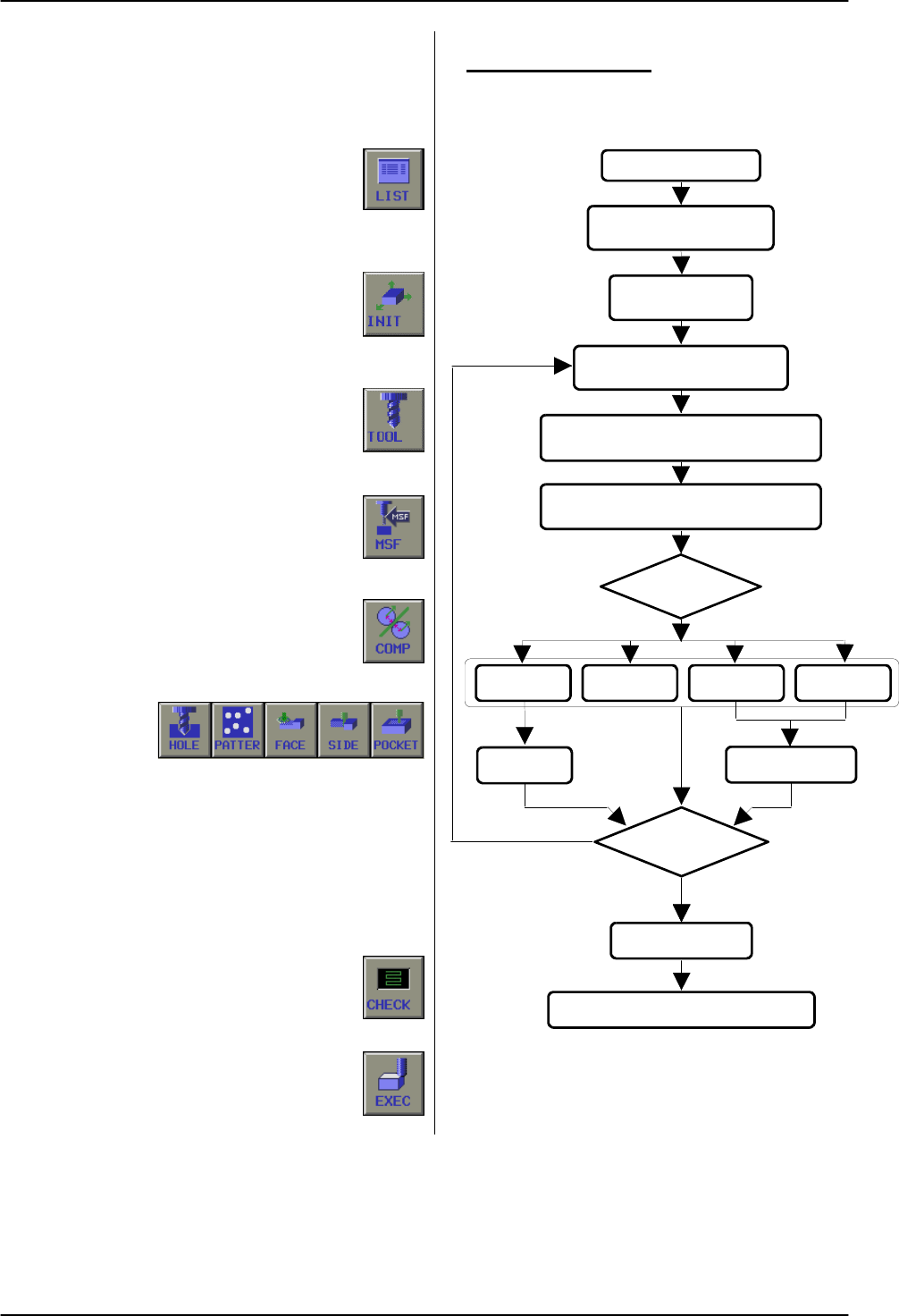
1. 3 Operation Flowchart
To prepare a new program or to edit a already
existing program, please see the Flow Chart beside.
1. Select LIST
In case of making a new program, input
not existing program No. In case of edit
a already existing program, select desired
program No. with cursor.
2. Select INIT
In case of graphic simulation should be
performed, in this menu blank dimension
for the workpiece are set. Otherwise not
necessary.
3. Select TOOL
This selection must be done to define the
tool, which will be used for the next
operation.
4. Select MSF
This selection must be done to define the
spindle speed and spindle rotation, which
will be used for the next operation.
5. Select COMP
This selection must be done to activate
the tool length offset, which will be used
for the next operation.
6. Select CYCLE
Several cycles
are available.
Some cycles needs additional cycles, like pattern
for drilling or contour figure definition for side
cutting or pocketing.
7. Program END? NO
In case that more then one tool will be used,
continue data input with a new tool definition and
all other operations util this item.
8. Graphic check
In case that no more tools will be used,
means program end, continue with graphic
check or execute machining program.
9. Execute machining program
The program can be used to run/execute
the machining program.
Making a new program
COMP
(Tool length compensation)
Select MSF
(Spindle speed and - rotation)
Select TOOL
(Tool definition menu)
Select INIT
(Initial Menu)
Input Program No.
Select LIST
Select Cycle
POCKETSIDEFACEHOLE
CONTOUR
Program End?
Graphic check
Execute machining program
YES
NO
PATTERN
Contents Summary of Manual Guide M Operators manual
- Page 1GE Fanuc Automation Europe Computer Numerical Controls Manual Guide Milling Handbook GFKE-0046A-EN TECHNOLOGY AND MORE�
- Page 2Manual Guide M Table of Contents Table of Contents 1 BASICS ..................................................................................................................................................................4 1. 1 Screen Layout .........................................................
- Page 3Manual Guide M Table of Contents 3. 2. 5 Boring Cycle G76 (Fine Boring).................................................................................................................49 3. 2. 6 Boring Cycle G87 (Back Boring)...........................................................................
- Page 4Manual Guide M Table of Contents 7. 7. 1 Contour Groove roughing ....................................................................................................................... 117 7. 7. 2 Movements in Contour Groove............................................................................
- Page 5Manual Guide M Basics 1 Basics …is your concise programming guide for the 'Manual Guide M' software of GE Fanuc CNN Controls, System 16i-M, 18i-M and 21i-M. For more comprehensive information on programming and operating, refer to the Document 'FANUC MANUAL GUIDE for Milling, Operator's Manual', B-6
- Page 6Manual Guide M Basics 1. 1 Screen Layout See 3 All in one screen 1. 1. 1 Operator Interface Title Area: 'Manual Guide M' uses only one screen, to present is displayed always all machining relevant operation! CNC status area: Following CNC status information are displayed always. - Mode Title area CN
- Page 7Manual Guide M Basics 1. 2 Operation Modes Following initial Soft-Keys are available. All functions 'Manual Guide M' enables different operation modes: and operations are arranged in the initial Soft-Keys. By pushing these Soft-Keys, the function will be 1. 2. 1 Manual Operation available. A machine
- Page 8Manual Guide M Basics 1. 3 Operation Flowchart Making a new program To prepare a new program or to edit a already existing program, please see the Flow Chart beside. 1. Select LIST Select LIST In case of making a new program, input not existing program No. In case of edit a already existing program,
- Page 9Manual Guide M Basics 1. 4 Program Manipulation Any program can be manipulated. Select LIST Soft-Key, to display screen beside. 1. 4. 1 Create new Program If a new program should be created, a new program No. has to be input. Existing programs are displayed in the pop-up window. 'Manual Guide M' can
- Page 10Manual Guide M Basics 1. 4. 4 Program Copy A complete program can be copied. Select program, which should be copied by cursor in the Program Directory, then Input New Program No., then push soft-key "EXEC" If going back to previous menu before EXEC, push soft-key CANCEL. 1. 4. 5 Program Delete To de
- Page 11Manual Guide M Basics 1. 5 Work Coordinate By pushing Soft-Key.'WRK CO', following pop up window is displayed. Work Coordinates are available from 01 (G54) to 06 (G59). Work Coordinate 00 (EXT), is to shift all offsets 01 to 06. With Soft-Key INPUT a absolute value is input. With Soft-Key +INPUT, th
- Page 12Manual Guide M Basics 1. 9 Absolute / Incremental Programming 1. 9. 1 Absolute Programming (G90) All programmed position values in X, Y and Z relates to the selected Work Coordinate Zero position. In the example beside it is the left lower corner of workpiece. Example with G90 Position 1 = X10 Y10 P
- Page 13Manual Guide M Details of Menu 2 Details of Menu Work Zero at Left Corner 2. 1 Initial Setting • First step is to insert Work Coordinate setting No. G54 to G59 (Default is G54). • Then the blank form has to be defined. • Data only required for graphic animation. • Input can be omitted, if no animati
- Page 14Manual Guide M Details of Menu 2. 2 Tool Setting Before any operation, a tool has to be defined. Any Data Input Pop-Up Menu kind of tool can be used. After pushing this soft-key "TOOL", the following pop-up window is displayed: Tool No.: Input the used Tool No. Cutter Offset No.: Input the used Radi
- Page 15Manual Guide M Details of Menu 2. 3 MSF Code Input This Menu allows defining M-Code as Auxiliary Data Input Pop-Up Menu Function: All available M-Codes displayed in the right side of the pop-up menu. S-Code, as Spindle speed F-Code as Feed Function, e.g. Single Operation, After pushing the soft-key
- Page 16Manual Guide M Details of Menu 2. 4 Compensation Data Input Pop-Up Menu This menu is used, to activate Tool Radius and Tool Length compensation. In case of using Cycle, only Tool Length compensation must be used. In case of single operations, like Line, Arc Clockwise or Arc Counter Clockwise, this m
- Page 17Manual Guide M Details of Menu 2. 5 Line This menu enables the Operator to define data for Data Input Pop-Up Menu "Line" cutting, such as Positioning in Rapid (G00) or Positioning as Linear Interpolation with Feed (G01). After pushing the soft-key "LINE", the following pop-up window is displayed: AB
- Page 18Manual Guide M Details of Menu 2. 6 Clockwise Circle Data Input Pop-Up Menu This menu enables the Operator to define data for "Circle Clockwise" cutting. After pushing the soft-key "ARC", the following pop-up window is displayed: G02 X_ Y_ I +_ ( J0 ) G02 X_ Y_ I -_J -_ Plane Selection: A arc can be
- Page 19Manual Guide M Details of Menu 2. 7 Counterclockwise Circle Data Input Pop-Up Menu This menu enables the Operator to define data for "Circle Clockwise" cutting. After pushing the soft-key "ARC", the following pop-up window is displayed: Plane Selection: A arc can be cut in 3 different G03 X_ Y_ I -_
- Page 20Manual Guide M Details of Menu 2. 8 Contour Programming Note This menu enables the Operator to define data for Contour data can be used even as separate Sub- free "CONTOUR" machining. This function can be Program. In this case the 'Contour' data profile can be used in conjunction with: called by M98
- Page 21Manual Guide M Details of Menu 2. 8. 1 Start This position must be a point of the figure itself. Detail Set Pop Up Menu Approach to this point is managed from one of the Menus Contour Inside / Outside or Contour Pocket or Contour Groove By pushing "DETAIL" Soft-Key Following pop-up window is display
- Page 22Manual Guide M Details of Menu 2. 8. 1. 1 Example CONTOUR GROOVE To cut the characters 'CONTOUR GROOVE' by using end mill, following procedure is necessary. CONTOUR GROOVE Please follow diagram on side. 1. After preparing data for Tool menu MSB menu and COMP menu 2. Select POCKET menu and then 3. Se
- Page 23Manual Guide M Details of Menu 2. 8. 2 Line A Line in any direction can be defined. Data Input Pop-Up Menu By pushing " LINE " Soft-Key the following pop-up window is displayed: Direction To select a ' Line direction ', following Soft-Key's are available: End Point X This is the Line end position in
- Page 24Manual Guide M Details of Menu Note If a line can not be clearly defined, by the normal input menu, the 'Detail' menu can be used to insert some Auxiliary data: Detail Set Pop-Up Menu By pushing "DETAIL" Soft-Key Following pop-up window is displayed: Component ANG-X Component ANG-Y If no End in X or
- Page 25Manual Guide M Details of Menu 2. 8. 3 Circle A circle in any direction, clockwise (CW) or Data Input Pop-Up Menu counter clockwise (CCW) can be defined. After pushing the Soft-Key " CW " or " CCW ", One of the following pop-up window is displayed: (CW or CCW are basically the same procedure) Radius
- Page 26Manual Guide M Details of Menu Note If a circle can not be clearly defined, by the normal Detail Set Pop-Up Menu input menu, the 'Detail' menu can be used to insert some additional data: By pushing "DETAIL" Soft-Key Following pop-up window is displayed: Coord. Length As a auxiliary data input, the C
- Page 27Manual Guide M Details of Menu 2. 8. 4 Chamfer A Chamfer is a part of a Figure, which can be input Input Data Input Pop-Up Menu between two other Contour Elements. After pushing the Soft-Key " CHAMF ", the following pop-up window is displayed: Chamfer between: Line / Line Circle / Circle Line / Circ
- Page 28Manual Guide M Details of Menu 2. 8. 5 Round A Round is a part of a Figure, which can be input Input Data Input Pop-Up Menu between two other Contour Elements. After pushing the Soft-Key " ROUND ", the following pop-up window is displayed: Round between: Line / Line Circle / Circle Line / Circle Cir
- Page 29Manual Guide M Details of Menu 2. 8. 6 End The End Soft-Key is used, when the contour or a Input Data Input Pop-Up Menu certain part of the figure input should be finished. After pushing the Soft-Key " END ", the following pop-up window is displayed: There are two possibilities to use the END-Menu.
- Page 30Manual Guide M Details of Menu No Pop-Up Menu in case of Tangent Selection 2. 8. 7 Tangent This command is used, if the next contour element should be 'Tangent' to the previous figure. One of these Contour Elements must be a arc. ( ( ( After pushing the Soft-Key " TANGENT ", ( No pop-up window is di
- Page 31Manual Guide M Details of Menu 2. 8. 10 Using Symbol Keys In Contour Menu the Symbol Keys are used, to define the contour figure. In following menus contour programming is available: • Direct Contour programming without cycle • Side Cutting programming, sub menu Contour • Pocketing programming, sub
- Page 32Manual Guide M Cycle Programming 3 CYCLE PROGRAMMING Important note: There are several Cycles available for frequently As to the detailed specifications, such as the restriction, needed machining operations. refer to the Operator's Manual describing the CNC of the FANUC Series 16/18/21i -MA Selectio
- Page 33Manual Guide M Cycle Programming 3. 1 DRILLING Important note Data for tool preparation and spindle speed has to be performed before in menu 'TOOL' and 'MSF'. There are several Drilling Cycles available: 3. 1. 1 Drilling Cycle (without dwell time) G81 This cycle is used for normal drilling. Cutting
- Page 34Manual Guide M Cycle Programming By pushing "DETAIL" Soft-Key Important note DETAIL SET screen - unnecessary to select. Usually preset values are suitable as default. Following pop-up window is displayed: ABS/INC Specify travel ways from the following soft-keys. [G90ABS (absolute)], [G91INC (increme
- Page 35Manual Guide M Cycle Programming 3. 1. 2 Drilling Cycle (with dwell time) G82 This cycle is used for normal drilling. Cutting feed is performed to the bottom of the hole. At the bottom, a dwell is performed, then the tool is retracted from the bottom of the hole in rapid traverse. By pushing [DWELL]
- Page 36Manual Guide M Cycle Programming By pushing "DETAIL" Soft-Key Important note DETAIL SET screen - unnecessary to select. Usually preset values are suitable as default. Following pop-up window is displayed: ABS/INC Specify travel ways from the following soft-keys. [G90ABS (absolute)], [G91INC (increme
- Page 37Manual Guide M Cycle Programming 3. 1. 3 Drilling Cycle (Peck) G83 This cycle performs peck drilling. It performs intermittent cutting feed to the bottom of a hole while removing shavings from the hole. And an arbor with the overload torque detection function is used to retract the tool when the ove
- Page 38Manual Guide M Cycle Programming By pushing "DETAIL" Soft-Key Important note DETAIL SET screen - unnecessary to select. Usually preset values are suitable as default. Following pop-up window is displayed: ABS/INC Specify travel ways from the following soft-keys. [G90ABS (absolute)], [G91INC (increme
- Page 39Manual Guide M Cycle Programming 3. 1. 3. 2 Small hole peck drilling cycle Small-Hole Peck Drilling Cycle This is special using of 'Peck drilling cycle'. G83 G83 (G98) (G99) Initial Point Point Point R The mode for 'Small-Hole Peck Drilling Cycle' is selected, when M-Code in parameter 5163 is Q Q sp
- Page 40Manual Guide M Cycle Programming 3. 1. 4 Drilling Cycle (High Speed Peck) G73 This cycle performs High-Speed peck drilling. It performs intermittent cutting feed to the bottom of a hole. By pushing [S-PECK], the following items are displayed G73 (G98) G73 (G99) Z POINT DISTANCE In the case G90 (Abso
- Page 41Manual Guide M Cycle Programming By pushing "DETAIL" Soft-Key Important note DETAIL SET screen - unnecessary to select. Usually preset values are suitable as default. Following pop-up window is displayed: ABS/INC Specify travel ways from the following soft-keys. [G90ABS (absolute)], [G91INC (increme
- Page 42Manual Guide M Cycle Programming 3. 2 BORING Important note Data for tool preparation and spindle speed has to be performed before in menu 'TOOL' and 'MSF'. There are several Boring Cycles available: 3. 2. 1 Boring Cycle G85 (Feed retraction) This cycle is used to bore a hole with feed retraction. B
- Page 43Manual Guide M Cycle Programming By pushing "DETAIL" Soft-Key Important note DETAIL SET screen - unnecessary to select. Usually preset values are suitable as default. Following pop-up window is displayed: ABS/INC Specify travel ways from the following soft-keys. [G90ABS (absolute)], [G91INC (increme
- Page 44Manual Guide M Cycle Programming 3. 2. 2 Boring Cycle G86 (Rapid retraction) This cycle is used for boring a hole with rapid retraction. By pushing [RAPID], the following items are displayed : G86 (G98) G86 (G99) Z POINT DISTANCE In the case G90 (Absolute = Default) Initial - the Z axis position of
- Page 45Manual Guide M Cycle Programming By pushing "DETAIL" Soft-Key Important note DETAIL SET screen - unnecessary to select. Usually preset values are suitable as default. Following pop-up window is displayed: ABS/INC Specify travel ways from the following soft-keys. [G90ABS (absolute)], [G91INC (increme
- Page 46Manual Guide M Cycle Programming 3. 2. 3 Boring Cycle G88 (Manual retraction) This cycle is used for boring a hole with manual retraction. By pushing [MANUAL], the following items are displayed : Z POINT DISTANCE G88 G88 In the case G90 (Absolute = Default) Spindle (G99) - the Z axis position of the
- Page 47Manual Guide M Cycle Programming By pushing "DETAIL" Soft-Key Important note DETAIL SET screen - unnecessary to select. Usually preset values are suitable as default. Following pop-up window is displayed: ABS/INC Specify travel ways from the following soft-keys. [G90ABS (absolute)], [G91INC (increme
- Page 48Manual Guide M Cycle Programming 3. 2. 4 Boring Cycle G89 (with Dwell Time) This cycle is used for boring a hole with dwell and rapid retraction. By pushing [DWELL], the following items are displayed : G89 (G98) G89 (G99) Z POINT DISTANCE In the case G90 (Absolute = Default) Initial - the Z axis pos
- Page 49Manual Guide M Cycle Programming By pushing "DETAIL" Soft-Key Important note DETAIL SET screen - unnecessary to select. Usually preset values are suitable as default. Following pop-up window is displayed: ABS/INC Specify travel ways from the following soft-keys. [G90ABS (absolute)], [G91INC (increme
- Page 50Manual Guide M Cycle Programming 3. 2. 5 Boring Cycle G76 (Fine Boring) The Fine Boring cycle bores a hole precisely. When the bottom of the hole has been reached, the spindle stops, and the tool is moved away from the machined surface of the work-piece and retraced. By pushing [FINE], the following
- Page 51Manual Guide M Cycle Programming By pushing "DETAIL" Soft-Key Important note DETAIL SET screen - unnecessary to select. Usually preset values are suitable as default. Following pop-up window is displayed: ABS/INC Specify travel ways from the following soft-keys. [G90ABS (absolute)], [G91INC (increme
- Page 52Manual Guide M Cycle Programming 3. 2. 6 Boring Cycle G87 (Back Boring) The Back Boring cycle enable to bore a hole from the backside. By pushing [BACK], the following items are displayed Z POINT DISTANCE G87 (G98) G87 (G99) In the case G90 (Absolute = Default) Q - the Z axis position of the bottom
- Page 53Manual Guide M Cycle Programming By pushing "DETAIL" Soft-Key Important note DETAIL SET screen - unnecessary to select. Usually preset values are suitable as default. Following pop-up window is displayed: ABS/INC Specify travel ways from the following soft-keys. [G90ABS (absolute)], [G91INC (increme
- Page 54Manual Guide M Cycle Programming 3. 3 TAPPING Important note Data for tool preparation and spindle speed has to be performed before in menu 'TOOL' and 'MSF'. There are several Tapping Cycles available: 3. 3. 1 Tapping Cycle G84 This cycle performs tapping. In this tapping cycle, when the bottom of t
- Page 55Manual Guide M Cycle Programming Important note By pushing "DETAIL" Soft-Key DETAIL SET screen - unnecessary to select. Usually preset values are suitable as default. Following pop-up window is displayed: ABS/INC Specify travel ways from the following soft-keys. [G90ABS (absolute)], [G91INC (increme
- Page 56Manual Guide M Cycle Programming 3. 3. 2 Left-handed Tapping Cycle G74 This cycle performs 'Left-handed' tapping. In this tapping cycle, spindle rotation starts counter clockwise, CCW. When the bottom of the hole has been reached, the spindle rotates in the normal direction. By pushing [REVTAP], the
- Page 57Manual Guide M Cycle Programming By pushing "DETAIL" Soft-Key Important note DETAIL SET screen - unnecessary to select. Usually preset values are suitable as default. Following pop-up window is displayed: ABS/INC Specify travel ways from the following soft-keys. [G90ABS (absolute)], [G91INC (increme
- Page 58Manual Guide M Cycle Programming 3. 3. 3 Rigid Tapping Cycle G84 This cycle performs 'Normal Rigid' tapping. When the spindle motor is controlled in rigid mode as if it were a servo motor, a tapping cycle can be speed up. And the rigid tapping cycle is useful. No special tool holder is necessary. By
- Page 59Manual Guide M Cycle Programming Important note By pushing "DETAIL" Soft-Key DETAIL SET screen - unnecessary to select. Usually preset values are suitable as default. Following pop-up window is displayed: ABS/INC Specify travel ways from the following soft-keys. [G90ABS (absolute)], [G91INC (increme
- Page 60Manual Guide M Cycle Programming 3. 3. 4 Left-handed Rigid Tapping Cycle G74 This cycle performs 'Left-handed' Rigid tapping. When the spindle motor is controlled in rigid mode as if it were a servo motor, a tapping cycle can be speed up. And the rigid tapping cycle is useful. No special tool holder
- Page 61Manual Guide M Cycle Programming By pushing "DETAIL" Soft-Key Important note DETAIL SET screen - unnecessary to select. Usually preset values are suitable as default. Following pop-up window is displayed: ABS/INC Specify travel ways from the following soft-keys. [G90ABS (absolute)], [G91INC (increme
- Page 62Manual Guide M Hole Pattern 4 HOLE PATTERN Important note: There are several Cycles available for frequently As to the detailed specifications, such as the restriction, needed machining operations. refer to the Operator's Manual describing the CNC of the FANUC Series 16/18/21i -MA Hole Pattern avail
- Page 63Manual Guide M Hole Pattern 4. 1 Hole Pattern Input Important note Before Pattern data input, one of the drilling cycles has to be performed first. 4. 1. 1 Single Points (G200) This is a menu for specifying the arbitrary hole positions. It is no limitation in No. of points to define, because this me
- Page 64Manual Guide M Hole Pattern 4. 1. 2 Line (G201) This is a menu for specifying the pattern of hole positions at the same or different spaces on arbitrary line. By pushing [LINE], the following pop-up window is displayed. In case of pattern SAME, following input items are available: Same Space START P
- Page 65Manual Guide M Hole Pattern In case of pattern DIFFER SPACE, following input Important note items are available: If more then 4 points has to be defined, push Soft-Key 'DETAIL', to continue input up to 10 points on the next page. If more then 10 points has to be defined, push Soft-Key CONT., to the
- Page 66Manual Guide M Hole Pattern 4. 1. 3 Grid (G202) This is a menu for specifying the pattern of hole positions of a grid. By pushing [GRID], the following pop-up window is displayed. START POINT X/Y X and Y coordinates of the first hole position, which is at the lower left position of the grid. U/V LEN
- Page 67Manual Guide M Hole Pattern 4. 1. 4 Square (G203) This is a menu for specifying the pattern of hole positions of a square. By pushing [SQUARE], the following pop-up window is displayed. START POINT X/Y X and Y coordinates of the first hole position, which is at the lower left position of the square.
- Page 68Manual Guide M Hole Pattern 4. 1. 5 Circle (G204) This is a menu for specifying the pattern of hole positions of a circle. By pushing [CIRCLE], the following pop-up window is displayed. CENTER X/Y X and Y coordinates of the center of the circle. RADIUS The radius of the circle START ANGLE The angle
- Page 69Manual Guide M Hole Pattern 4. 1. 6 Arc (G205) This is a menu for specifying the pattern of hole positions at the same or different spaces on arbitrary line. By pushing [ARC], the following pop-up window is displayed. In case of pattern SAME, following input items are available: Same Space CENTER X
- Page 70Manual Guide M Hole Pattern In case of pattern DIFFER SPACE, following input items are available: Important note If more then 2 points has to be defined, push Soft-Key 'DETAIL', to continue input up to 10 points on the next page. If more then 10 points has to be defined, push SpaceCONT., to the same
- Page 71Manual Guide M Facing 5 FACING Important note: There are several Cycles available for frequently As to the detailed specifications, such as the restriction, needed machining operations. refer to the Operator's Manual describing the CNC of the FANUC Series 16/18/21i -MA Two Facing cycles are availabl
- Page 72Manual Guide M Facing 5. 1 Square Surface (G210) Important note Facing can be performed as: Data for tool preparation, spindle speed and tool length ROUGHING and FINISHING compensation has to be performed before in menu 'TOOL', 'MSF' and 'COMP'. This is a menu for facing the surface on a square shap
- Page 73Manual Guide M Facing By pushing "DETAIL" Soft-Key Important note DETAIL SET screen - unnecessary to select. Usually preset values are suitable as default. Following pop-up window is displayed: CLEARANCE The amount of clearance for cutting feed in Z axis at the approach and escape movement. The defa
- Page 74Manual Guide M Facing 5. 2 Circle Surface (G211) Important note Facing can be performed as: Data for tool preparation, spindle speed and tool length ROUGHING and FINISHING compensation has to be performed before in menu 'TOOL', 'MSF' and 'COMP'. This is a menu for facing the surface on a circle shap
- Page 75Manual Guide M Facing By pushing "DETAIL" Soft-Key Important note DETAIL SET screen - unnecessary to select. Usually preset values are suitable as default. Following pop-up window is displayed: CLEARANCE The amount of clearance for cutting feed in Z axis at the approach and escape movement. The defa
- Page 76Manual Guide M Contour Side Cutting 5. 3 Contour Side (G223) 5. 3. 1 Contour Side roughing Important note Data for tool preparation, spindle speed and tool length compensation has to be performed before in menu 'TOOL', 'MSF' and 'COMP'. This is a menu to cut an Arbitrary Shape Side only. In this men
- Page 77Manual Guide M Contour Side Cutting Roughing 2/2 Roughing 2/2 FEED RATE The feed rate of the tool in XY direction. Z CUT FEED RATE Feed rate in Z direction from R-point to bottom. COMP. DIRECTION Select the compensation direction by following Soft-Keys: Important note: After all data input in the me
- Page 78Manual Guide M Contour Side Cutting By pushing "DETAIL" Soft-Key Important note DETAIL SET screen - unnecessary to select. Usually preset values are suitable as default. Following pop-up window is displayed: CLEARANCE The amount of clearance for cutting feed in Z axis at the approach and escapes mov
- Page 79Manual Guide M Contour Side Cutting 5. 3. 2 Movements in Contour Side Important note In Contour Side menu, cutter compensation G41 and G42 Movements are basically similar in all side cutting are used. In this case the work piece dimension can be influenced by modifying cutter radius offset value. me
- Page 80Manual Guide M Contour Side Cutting 5. 3. 2. 3 Movements in Side finishing Movements in Side finishing 1. Rapid in XY to start point ( A ) 2. Rapid in Z to point R (end Z + bottom removal + clearance). Point R 3. Descent along the lower Z position with Z feed. Bottom Pitch Clearance Z 4. Move into t
- Page 81Manual Guide M Side Cutting 6 SIDE CUTTING Important note: There are several Cycles available for frequently As to the detailed specifications, such as the restriction, needed machining operations. refer to the Operator's Manual describing the CNC of the FANUC Series 16/18/21i -MA Fife Side Cutting
- Page 82Manual Guide M Side Cutting 6. 2 Square Side (G220) 6. 2. 1 Square Side roughing Important note Data for tool preparation, spindle speed and tool length compensation has to be performed before in menu 'TOOL', 'MSF' and 'COMP'. This is a menu for cutting a square shape on side, inside or outside. By
- Page 83Manual Guide M Side Cutting Roughing 2/2 Roughing 2/2 FEED RATE The feed rate of the tool. Z CUT FEED RATE Feed rate in Z direction from R-point to bottom. MACH. SHAPE Select machine shape from soft-keys: OUTSIDE or INSIDE CENTER POINT X X coordinate of square center. CENTER POINT Y Y coordinate of
- Page 84Manual Guide M Side Cutting By pushing "DETAIL" Soft-Key Important note DETAIL SET screen - unnecessary to select. Usually preset values are suitable as default. Following pop-up window is displayed: CLEARANCE The amount of clearance for cutting feed in Z axis at the approach and escape movement. Th
- Page 85Manual Guide M Side Cutting 6. 2. 2 Movements in Side Square Movements are similar in all Side Cutting Menus. Rapid Traverse (G00) Feed Traverse (G01) 6. 2. 2. 1 Movements in Outside roughing Outside Roughing 1. Rapid in XY to start point A 2. Rapid in Z to point R Point R Bottom Pitch 3. Descent al
- Page 86Manual Guide M Side Cutting 6. 2. 2. 4 Movements in Side finishing Outside Movement 1. Rapid in XY to start point ( B ) 2. Rapid in Z to cutting point (is calculated by : End Z, bottom removal, Z cut Point R Bottom Pitch Z Clearance step, clearance). Bottom Removal 3. Descent along the lower Z posit
- Page 87Manual Guide M Side Cutting 6. 3 Circle Side (G221) 6. 3. 1 Circle Side roughing Important note Data for tool preparation, spindle speed and tool length compensation has to be performed before in menu 'TOOL', 'MSF' and 'COMP'. This is a menu for cutting a circle shape on side, inside or outside. By
- Page 88Manual Guide M Side Cutting Roughing 2/2 Roughing 2/2 FEED RATE The feed rate of the tool. Z CUT FEED RATE Feed rate in Z direction from R-point to bottom. MACH. SHAPE Select machine shape from soft-keys: OUTSIDE or INSIDE CENTER POINT X X coordinate of Track center. CENTER POINT Y Y coordinate of T
- Page 89Manual Guide M Side Cutting By pushing "DETAIL" Soft-Key Important note DETAIL SET screen - unnecessary to select. Usually preset values are suitable as default. Following pop-up window is displayed: CLEARANCE The amount of clearance for cutting feed in Z axis at the approach and escape movement. Th
- Page 90Manual Guide M Side Cutting 6. 4 Track Side (G222) 6. 4. 1 Track Side roughing Important note Data for tool preparation, spindle speed and tool length compensation has to be performed before in menu 'TOOL', 'MSF' and 'COMP'. This is a menu for cutting a Track shape on side, inside or outside. By pus
- Page 91Manual Guide M Side Cutting Roughing 2/2 Roughing 2/2 FEED RATE The feed rate of the tool. Z CUT FEED RATE Feed rate in Z direction from R-point to bottom. MACH. SHAPE Select machine shape from soft-keys: OUTSIDE or INSIDE CENTER POINT X X coordinate of square center. CENTER POINT Y Y coordinate of
- Page 92Manual Guide M Side Cutting By pushing "DETAIL" Soft-Key Important note DETAIL SET screen - unnecessary to select. Usually preset values are suitable as default. Following pop-up window is displayed: CLEARANCE The amount of clearance for cutting feed in Z axis at the approach and escape movement. Th
- Page 93Manual Guide M Side Cutting 6. 5 One Side (G223) 6. 5. 1 One Side roughing Important note Data for tool preparation, spindle speed and tool length compensation has to be performed before in menu 'TOOL', 'MSF' and 'COMP'. This is a menu for cutting One Side only. By pushing [ONE SD], the following po
- Page 94Manual Guide M Side Cutting Roughing 2/2 Roughing 2/2 FEED RATE The feed rate of the tool. Z CUT FEED RATE Feed rate in Z direction from R-point to bottom. CENTER POINT X X coordinate of Side figure center. CENTER POINT Y Y coordinate of Side figure center. U-LENGTH The Length of the specified side
- Page 95Manual Guide M Side Cutting By pushing "DETAIL" Soft-Key Important note DETAIL SET screen - unnecessary to select. Usually preset values are suitable as default. Following pop-up window is displayed: CLEARANCE The amount of clearance for cutting feed in Z axis at the approach and escape movement. Th
- Page 96Manual Guide M Side Cutting 6. 5. 2 Movements in One Side Movements are basically similar in all side cutting menus, but in case of 'One Side' menu a little bit different. Rapid Traverse (G00) Feed Traverse (G01) 6. 5. 2. 1 Movements rough cutting Movements in cutting One-Side 12. Rapid in XY to sta
- Page 97Manual Guide M Side Cutting 6. 5. 2. 3 Movements in Side finishing Movements in cutting One-Side 11. Rapid in XY to start point ( A ) 12. Rapid in Z to point R (end Z + bottom removal + clearance). Point R Bottom Pitch 13. Rapid towards to one side end position. Z Clearance 14. Descent along the low
- Page 98Manual Guide M Pocketing 7 POCKETING Important note: There are several Cycles available for frequently As to the detailed specifications, such as the restriction, needed machining operations. refer to the Operator's Manual describing the CNC of the FANUC Series 16/18/21i -MA Fife Pocketing cycles ar
- Page 99Manual Guide M Pocketing 7. 2 Square Pocket (G230) 7. 2. 1 Pocket roughing Important note Data for tool preparation, spindle speed and tool length compensation has to be performed before in menu 'TOOL', 'MSF' and 'COMP'. Several Pocketing Cycles are available, please see below. By pushing [SQUARE ],
- Page 100Manual Guide M Pocketing Roughing 2/2 Roughing 2/2 Z CUT FEED RATE Feed rate in Z direction from R-point to bottom CENTER POINT X X coordinate of pocket center. CENTER POINT Y Y coordinate of pocket center. U LENGTH The horizontal length of pocket . V LENGTH The vertical length of pocket . GE Fanuc
- Page 101Manual Guide M Pocketing By pushing "DETAIL" Soft-Key Important note DETAIL SET screen - unnecessary to select. Usually preset values are suitable as default. Following pop-up window is displayed: CLEARANCE The amount of clearance for cutting feed in Z axis at the approach and escape movement. The d
- Page 102Manual Guide M Pocketing 7. 2. 2 Movements in Square Pocket Movements are similar in all Pocketing Menus. Rapid Traverse (G00) Feed Traverse (G01) 7. 2. 2. 1 Movements in Roughing Square Pocket, Roughing 1. Rapid in XY to start point. 2. Rapid in Z to point R. 3. Descent along the lower Z position w
- Page 103Manual Guide M Pocketing 7. 2. 2. 4 Movements in Chamfering Movements in Chamfering 13. Rapid in XY to start point. 14. Rapid in Z to the cutting point. Removal Pitch Clearance (is calculated by : End point Z , bottom removal, Point R chamfer removal, tool small diameter, chamfer Z Removal Depth ang
- Page 104Manual Guide M Pocketing 7. 3 Circle Pocket (G231) 7. 3. 1 Circle Pocket roughing Important note Data for tool preparation, spindle speed and tool length compensation has to be performed before in menu 'TOOL', 'MSF' and 'COMP'. Several Pocketing Cycles are available, please see below. By pushing [CI
- Page 105Manual Guide M Pocketing Roughing 2/2 Roughing 2/2 Z CUT FEED RATE Feed rate in Z direction from R-point to bottom. CENTER POINT X X coordinate of Circle center. CENTER POINT Y Y coordinate of Circle center. RADIUS The Radius of the circle. GE Fanuc Automation S.A. - 104 - GFKE-0046-EN/01�
- Page 106Manual Guide M Pocketing By pushing "DETAIL" Soft-Key Important note DETAIL SET screen - unnecessary to select. Usually preset values are suitable as default. Following pop-up window is displayed: CLEARANCE The amount of clearance for cutting feed in Z axis at the approach and escape movement. The d
- Page 107Manual Guide M Pocketing 7. 4 Track Pocket (G232) 7. 4. 1 Track Pocket roughing Important note Data for tool preparation, spindle speed and tool length compensation has to be performed before in menu 'TOOL', 'MSF' and 'COMP'. Several Pocketing Cycles are available, please see below. By pushing [ TRA
- Page 108Manual Guide M Pocketing Track Roughing 2/2 Track Roughing 2/2 Z CUT FEED RATE Feed rate in Z direction from R-point to bottom. CENTER POINT X X coordinate of Track center. CENTER POINT Y Y coordinate of Track center. RADIUS The Radius of the circle. GE Fanuc Automation S.A. - 107 - GFKE-0046-EN/01�
- Page 109Manual Guide M Pocketing By pushing "DETAIL" Soft-Key Important note DETAIL SET screen - unnecessary to select. Usually preset values are suitable as default. Following pop-up window is displayed: CLEARANCE The amount of clearance for cutting feed in Z axis at the approach and escape movement. The d
- Page 110Manual Guide M Pocketing 7. 5 Groove Pocket (G233) 7. 5. 1 Groove Pocket roughing Important note Data for tool preparation, spindle speed and tool length compensation has to be performed before in menu 'TOOL', 'MSF' and 'COMP'. Several Pocketing Cycles are available, please see below. By pushing [ G
- Page 111Manual Guide M Pocketing Groove Roughing 2/2 Groove Roughing 2/2 CENTER POINT X X coordinate of Groove center. CENTER POINT Y Y coordinate of Groove center. U-LENGTH The length of the Groove. GROOVE WIDTH The width of the Groove. GE Fanuc Automation S.A. - 110 - GFKE-0046-EN/01�
- Page 112Manual Guide M Pocketing By pushing "DETAIL" Soft-Key Important note DETAIL SET screen - unnecessary to select. Usually preset values are suitable as default. Following pop-up window is displayed: CLEARANCE The amount of clearance for cutting feed in Z axis at the approach and escape movement. The d
- Page 113Manual Guide M Contour Pocket Cutting 7. 6 Contour Pocket (G234) 7. 6. 1 Contour Pocket roughing Important note Data for tool preparation, spindle speed and tool length compensation has to be performed before in menu 'TOOL', 'MSF' and 'COMP'. This is a menu to cut a Arbitrary Shape Pocket only. In t
- Page 114Manual Guide M Contour Pocket Cutting Roughing 2/2 Roughing 2/2 FEED RATE The feed rate of the tool in XY direction. Z CUT FEED RATE Feed rate in Z direction from R-point to bottom. Important note: After all data input in the menu 'Contour Pocketing', the system automatically switches over 'Contour'
- Page 115Manual Guide M Contour Pocket Cutting By pushing "DETAIL" Soft-Key Important note DETAIL SET screen - unnecessary to select. Usually preset values are suitable as default. Following pop-up window is displayed: CLEARANCE The amount of clearance for cutting feed in Z axis at the approach and escape mo
- Page 116Manual Guide M Contour Pocket Cutting 7. 6. 2 Movements in Contour Pocket Important note In Contour Pocket menu, cutter compensation G41 and Movements are basically similar in all pocketing G42 are used. In this case the work piece dimension can menus, but in case of 'Contour Pocket' menu a little b
- Page 117Manual Guide M Contour Pocket Cutting 7. 6. 2. 3 Movements Pocket Side finishing Movements Pocket Side finishing 30. Rapid in XY to start point. 31. Rapid in Z to point R Removal Pitch (end Z + bottom removal + clearance). Point R Clearance 32. Descent along the lower Z position with Z feed by the d
- Page 118Manual Guide M Contour Pocket Cutting 7. 7 Contour Groove (G235) 7. 7. 1 Contour Groove roughing Important note Data for tool preparation, spindle speed and tool length compensation has to be performed before in menu 'TOOL', 'MSF' and 'COMP'. This is a menu to cut a Arbitrary Shape Groove only. In t
- Page 119Manual Guide M Contour Pocket Cutting Roughing 2/2 Roughing 2/2 FEED RATE The feed rate of the tool in XY direction. Z-CUT FEED RATE The cutting feed rate in Z direction from point R. GROOVE WIDTH The width of the groove. Important note: After all data input in the menu 'Contour Pocketing', the syst
- Page 120Manual Guide M Contour Pocket Cutting By pushing "DETAIL" Soft-Key Important note DETAIL SET screen - unnecessary to select. Usually preset values are suitable as default. Following pop-up window is displayed: CLEARANCE The amount of clearance for cutting feed in Z axis at the approach and escape mo
- Page 121Manual Guide M Contour Pocket Cutting 7. 7. 2 Movements in Contour Groove Important note In Contour Groove menu, cutter compensation G41 and Movements are basically similar in all pocketing G42 are used. In this case the work piece dimension can menus, but in case of 'Contour Groove' menu a little b
- Page 122Manual Guide M Contour Pocket Cutting 7. 7. 2. 3 Movements in Groove finishing Movements in cutting Contour Groove 1. Rapid in XY to start point (A). 2. Rapid in Z to point R (end Z + bottom removal + clearance). Removal Pitch 3. Descent along the lower Z position with Z feed by Point Clearance Z th
- Page 123Manual Guide M Advanced Programming 8 ADVANCED PROGRAMMING 8. 1 Finish / Chamfer / Pre-Hole In milling menus are finishing, chamfering and pre- hole drilling processes available. • FACING face finish • SIDE Square bottom / side finish, chamfer SIDE Circle SIDE Track SIDE One Side SIDE Contour no cha
- Page 124Manual Guide M, Guide Advanced Programming 8. 2 Face finishing 8. 2. 1 Prepare Finishing Menu Important note In case that FINISHING is necessary, make sure, that in ROUGHING process the finishing amount is set. Finishing needs normally a different tool and other cutting condition then for roughing.
- Page 125Manual Guide M, Guide Advanced Programming 8. 2. 2 Usage of COPY Function Copy function can be used, to simplify data input for Finishing, Chamfering or Pre-Hole drilling. The data input menus are basically the same as roughing. If roughing data are copied, only small modifications are necessary to
- Page 126Manual Guide M, Guide Advanced Programming 8. 3 Side Finish/Chamfer 8. 3. 1 Prepare Finish/Chamfer Menu Important note In case that 'B-FIN' or 'S-FIN', Finish or Chamfer is necessary, make sure, that in ROUGHING process the Side, Z-Finish or Chamfer amount is input. Select one of the MACH. PROCESS b
- Page 127Manual Guide M, Guide Advanced Programming 8. 3. 2 Other Side Finish/Chamfer Important note In case that 'B-FIN' or 'S-FIN', Finishing is necessary, make sure, that in ROUGHING process the Side- and Z-Finishing amount is input Side Finish and Chamfer processes are very similar in all Side Cutting me
- Page 128Manual Guide M, Guide Advanced Programming 8. 4 Pocket Finish/Chamfer 8. 4. 1 Prepare Finish/Chamfer Menu Important note In case that 'B-FIN' or 'S-FIN', Finish or Chamfer is necessary, make sure, that in ROUGHING process the Side, Z-Finish or Chamfer amount is input. Select one of the MACH. PROCESS
- Page 129Manual Guide M, Guide Advanced Programming 8. 4. 2 Other Pocket Finish/Chamfer Important note In case that 'B-FIN' or 'S-FIN', Finishing is necessary, make sure, that in ROUGHING process the Side- and Z-Finishing amount is input Pocket Finish, Chamfer and Pre-Hole drilling processes are ver similar
- Page 130Manual Guide M, Guide Advanced Programming 8. 5 Contour Sub Program C-GROO Contour programming is available for following menus: • CONTR Direct Contour, without cycle • SIDE CONTR Cycle Contour, Out-/Inside • POCKET CONTR Cycle Contour Pocket C-GROV Cycle Contour Groove Contour Positive (Propeller)
- Page 131Manual Guide M, Guide Advanced Programming 8. 5. 1 Example Propeller R7 In this example, Propeller Positive and Negative, 10 cycle Pocket is used in both cases. Positive In case of Positive, Contour Pocket with Island is 120° defined, to cut all material from the Blank, which is R 20 53 defined as B
- Page 132Manual Guide M Appendix Appendix A-1. Tools for Drilling and Milling Tools for Drilling Tools for Milling Important note It is a EXCEL file available, to calculate spindle speed and feed according specified data automatically. Please use: tool-plan_R-F.xls. GE Fanuc Automation S.A. - 131 - GFKE-0046
- Page 133Manual Guide M Appendix A-2. Workpiece Setup Plan Vertical Machining Center GE Fanuc Automation S.A. - 132 - GFKE-0046-EN/01�
- Page 134Manual Guide M Appendix Setup Plan Horizontal Machining Center GE Fanuc Automation S.A. - 133 - GFKE-0046-EN/01�
- Page 135Manual Guide M Appendix A-3. Tool Plan Workpiece Name : V = m/min HM F V = m/min HM R V = m/min HSS F Work Piece Material : V = m/min HSS R No. T-Code Diam. No.Teeth Tool-Mat. Tool Name F mm/tooth S U/min F mm/min 1 2 3 4 5 6 7 8 9 10 11 12 13 14 15 16 17 18 19 20 21 22 23 24 25 26 27 28 29 30 31 32
- Page 136Manual Guide M Programming Examples A-4. Programming Examples A-4.1. Example 1 A-4.1.1. Blank Definition Work Zero definition: 100 Basically the Work Zero Offset position can be set according drawing design to the center or to any R10 other position. R25 In this example, it would be the best way, to
- Page 137Manual Guide M Programming Examples A-4.1.2. Contour Side Cutting A-4.1.2.1. Roughing only Material = ST 50 100 End mill tool Diameter = 16 R10 Tool material = HM (Carbide) No. of teeth = 4 R25 Cutting speed HM (Carbide) = 190 m/min Feed per tooth = 0.06 mm/min 80 Spindle speed = 3781 Rpm R20 Feed r
- Page 138Manual Guide M Programming Examples A-4.1.2.2. Contour Definition Select Contour 100 R10 START = X0 Y0 R25 Start point type 80 START R20 LINE Y = 30 30 R18 GEF #FL / ZBF-005 150 CORNER = 18 LINE X = 50 Contour side cutting solid graphic CORNER = 20 LINE Y = 80 CORNER = 10 LINE X = 150 CORNER = 25 LI
- Page 139Manual Guide M Programming Examples 10 A-4.2. Example 2 15 30 A-4.2.1. Blank Definition Solid Graphic of Blank Work Zero definition; Basically Work Zero Offset position can be set R12 according drawing design to the center or to any other position. 160 164 In this example, it would be the best way,
- Page 140Manual Guide M Programming Examples 10 A-4.2.2. Facing 15 A-4.2.2.1. Surface 200 x 200 30 Material = ST 50 Face milling tool Diameter = 63 No. of teeth = 5 R12 Cutting speed HM (Carbide) = 200 m/min Feed per tooth = 0.25 mm/min Spindle speed = 1011 Rpm 160 164 Feed rate = 1263 mm/min 100 200 Materia
- Page 141Manual Guide M Programming Examples 10 A-4.2.3. Side Cutting 15 A-4.2.3.1. Outside Circle ∅ 160 30 End mill tool Diameter = 32 No. of teeth = 4 Cutting speed HM (Carbide) = 200 m/min Feed per tooth = 0.06 mm/min R12 Spindle speed = 1990 Rpm Feed rate = 478 mm/min 160 164 Material to cut at side in t
- Page 142Manual Guide M Programming Examples 10 A-4.2.4. Pocketing 15 A-4.2.4.1. Pocket 100 x 100 x 10 30 End mill tool Diameter = 20 No. of teeth = 4 Cutting speed HM (Carbide) = 200 m/min Feed per tooth = 0.05 mm/min R12 Spindle speed = 3184 Rpm Feed rate = 637 mm/min 160 164 Material to cut in pocket in t
- Page 143Manual Guide M Programming Examples 10 A-4.2.5. Drilling 15 A-4.2.5.1. Drilling ∅ 20 30 Drill tool Diameter = 20 Cutting speed HSS = 25 m/min Feed per revolution = 0.22 mm/Ref R12 Spindle speed = 398 Rpm Feed rate = 88 mm/min 160 164 Material to drill in total (depth) = 30 + 7 (through) 100 200 Dril
- Page 144Manual Guide M Programming Examples R4 A-4.3. Example 3 30 A-4.3.1. Blank Definition 45 R10 R8 Work Zero definition: Basically the Work Zero Offset position can be set according drawing design to the center or to any other position. In this example, it would be the best way, to select GEF #FL / ZBF-
- Page 145Manual Guide M Programming Examples A-4.3.2. Contour Side Cutting A-4.3.2.1. Roughing only Material = ALUMINIUM R4 End mill tool Diameter = 10 30 Tool material = HSS No. of teeth = 3 45 R10 Cutting speed HSS = 70 m/min R8 Feed per tooth = 0.06 mm/min Spindle speed = 2229 Rpm Feed rate = 401 mm/min M
- Page 146Manual Guide M Programming Examples A-4.3.2.2. Contour Definition Select Contour START = X30 Y0 Figure definition from Start point (7) to Start point type temporary end point (12). START CIRCLE R = 10 Center point X = 20 Center point Y = 0 TANGNT LINE = LEFT-UP Angle 30 Degree TANGNT CIRCLE R = 4 TA