QuickTurn Electronic Lathe Version 0i_V1_10 Operators manual Page 26
Operators manual
QuickTurn™
GE Fanuc Automation S.A. Page 25 GFKE-0047C-EN
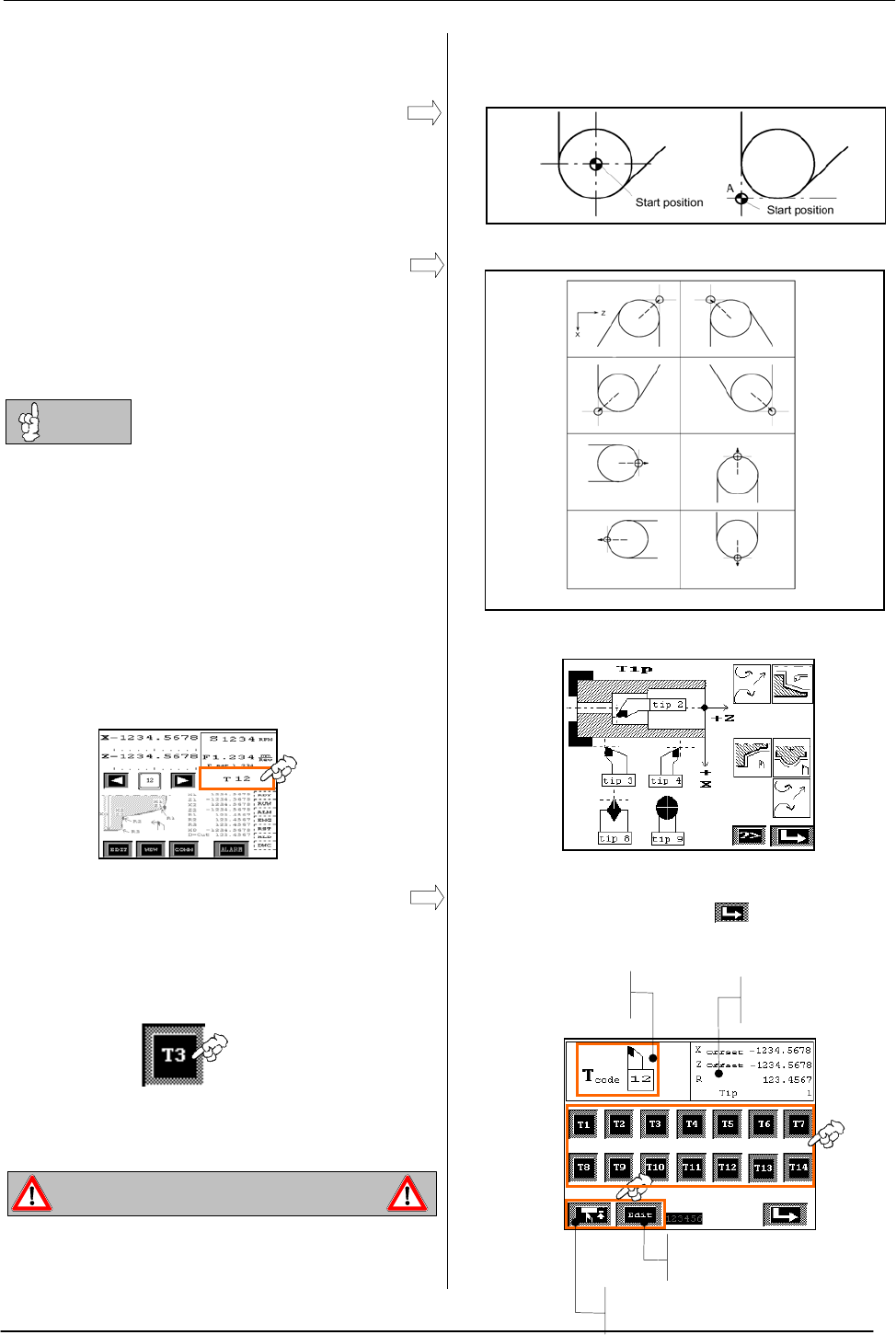
5.2.1 Imaginary Tool Tip
The imaginary tool nose is required because it is
usually more difficult to program the actual tool
nose radius center as start point, than the
imaginary tool nose.
According to the direction of the used tool,
imaginary tool tip needs to be set in different way.
When the imaginary tool nose is used, the tool
nose radius need not to be considered in
programming.
If tool radius is set to R=0, tool radius
compensation is not performed. In standard
machining tool radius compensation is not needed
(Standard R=0). If high accuracy of radius cutting
is needed set radius and tip accordingly.
5.3 Tool Activation
Press on tool display area of main screen to open
tool selection screen.
To activate a tool press on icons T1 to T14.
T-Code and display of tool geometry data is
refreshed according to selected tool.
Activation of tool
If tool length offsets, radius or tip data are set
incorrectly, the tool may bump against the
workpiece or machine.
Settings for imaginary tool tip
Tool tip setting help screen
Tool selection screen, press to return to main
screen.
WARNING: Danger for the user of the machine
Display of Active
Tool Number
Geometry Display
of Active Tool
Opens Offset
Measurement Screen
Opens Offset
Editing Screen
Tip =4 Tip =3
Tip =2 Tip =1
Tip =5
Tip =8
Tip =7 Tip =6
Tip =9
NOTE
Contents Summary of QuickTurn Electronic Lathe Version 0i_V1_10 Operators manual
- Page 1GE Fanuc Automation QuickTurn™ Electronic Lathe Operator’s Manual GFKE-0047C-EN Software Version Oi_V1_10 February 2004
- Page 2QuickTurn™ GE Fanuc Automation S.A. Page 1 GFKE-0047C-EN
- Page 3QuickTurn™ Table of Content 1 MAIN SCREEN.......................................................................................................................................................3 2 OPERATION METHODS.......................................................................................
- Page 4QuickTurn™ 1 Main screen All machining operations can be executed from the main screen. Sub screens are used for preparatory functions like work piece zero point setting, feedrate setting, cycle selection, cycle editing. Up to 40 cycles can be saved into CNC memory. Touch Area Opens Touch Area Zero
- Page 5QuickTurn™ 2 Operation Methods Select memory position 0. Machine can be used in different ways. Manual Cutting Machine can be used as a normal manual turning machine by moving axis by hand wheel or joystick for continuous feed without any support by CNC control. The position display can be used to c
- Page 6QuickTurn™ 3 Preparatory Operations Following preparatory operations must always be Machining operation flow chart done before starting machining. - Work Coordinate Setting Step 1 Work Coordinate Setting - Cutting Feedrate Setting - Spindle Speed Setting (Only on machines having a frequency converte
- Page 7QuickTurn™ 3.1 Work Coordinate Setting Description of Coordinate System Press on coordinate display of main screen to open woorkcoordinate setting screen. Z+ X- Z- X+ Before starting any kind of machining operation, work coordinates (workpiece zero) must be set. By pressing on X or Z touch areas, da
- Page 8QuickTurn™ 3.2 Feedrate Setting Before starting a cycle based machining operation by pressing START button on machine, cutting feedrate needs to be set (Except DNC mode). Feedrate set used in following two machining operations: - Feedrate for cutting during cycles. - Feedrate for cutting when moving
- Page 9QuickTurn™ 3.3 Spindle Speed Setting Press on spindle speed display of main screen to Before starting any kind of machining operation, open spindle speed setting screen. spindle speed must be set. (Spindle speed setting screen is available only if machine is equipped with frequency converter option)
- Page 10QuickTurn™ 4 Cycles 4.1 Basics Geometry data of 40 cycles can be saved to CNC in memory positions from 1 to 40. Memory position 0 is always empty, this means no cycle can be saved to position 0. 4.1.1 Selecting a Memory Position Main Screen Memory positions are selected by pressing on arrow touch ar
- Page 11QuickTurn™ 4.1.5 Overview of Available Cycles Cycle selection screen. To select a cycle press on By pressing icon on main screen cycle touch areas. Press to return to main screen selection screen opens. - Stop Cycles - Standard - Face - Taper Cycles - Threading Cycles - Grooving Cycles - External Ra
- Page 12QuickTurn™ 4.2.1 Standard Stop Cycles To machine a part, position tool by means of hand wheels or joystick in X and Z direction to cutting start point and press start button on machine. When using STANDARD stop cycles, tool Tool path of STANDARD stop cycles. performs one linear cut to workpiece shap
- Page 13QuickTurn™ 4.2.2 Face Stop Cycles To machine a part, position tool by means of hand wheels or joystick in X and Z direction to cutting start point and press start button on machine. When using FACE stop cycles, tool performs a Tool path of FACE stop cycles. linear approach movement in cutting feed.
- Page 14QuickTurn™ 4.3 Taper Cycles By pressing icon on cycle selection screen, Taper cycle selection screen. To select cycle and taper cycle selection screen opens. Cycles use edit geometry data press on touch areas. Press radius compensation. to return to main screen. Three taper cycles are available. - O
- Page 15QuickTurn™ 4.4 Threading Cycles By pressing icon on cycle selection screen, Threading cycle selection screen. To select cycle threading selection screen opens. and edit geometry data press on touch areas. Press to return to main screen. Four threading cycles are available. - Outer Threading - Inner
- Page 16QuickTurn™ 4.4.2 Outer and Inner Thread Repair This cycle is a complete automatic cycle to repair a thread that has been damaged. Basically this cycle works like the normal threading cycle with a shifted cutting start point. By ”teaching in” location of thread, the start point shift is calculated by
- Page 17QuickTurn™ 4.5 Grooving Cycles Grooving cycle selection screen. To select cycle By pressing icon on cycle selection screen, and edit geometry data press on touch areas. grooving selection screen opens. Press to return to main screen. Three grooving cycles are available. - Outer Grooving - Inner Groo
- Page 18QuickTurn™ 4.6 Radius Cutting Cycles Radius cutting cycle selection screen. To select By pressing icon on cycle selection screen, cycle and edit geometry data press on touch radius cutting cycle selection screen opens. areas. Press to return to main screen. Cycles use radius compensation. Following
- Page 19QuickTurn™ NOTE1 By positioning tool exactly to radius start point X1 and pressing start button on machine, tool directly performs finish cut, or semi finish cut if tool is in range [X1+Finish Amount] In order to machine figure of example 1and example 2 it is necessary to program an outer concave ra
- Page 20QuickTurn™ 4.7 Drilling and Tapping Cycle Tapping and drilling cycle selection screen. To By pressing icon on cycle selection screen, select cycle and edit geometry data press on drilling and tapping cycle selection screen opens. touch areas. Press to return to main screen. Following cycles are avai
- Page 21QuickTurn™ 4.8 Facing Cycle By pressing icon on cycle selection screen, Input mask of facing cycle. Press to save facing cycle data input screen opens data, press to return to main screen without saving data. Press to add spindle speed, federate and tool data to cycle. Facing cycle input data - Xe:
- Page 22QuickTurn™ 4.9 Single Block Cycle By pressing icon on cycle selection screen, Input mask of single block cycle. single block cycle data input screen opens. Press to save data, press to open next screen for blocks 6 to 10, press to return to The single block cycle allows to specify 10 points. main sc
- Page 23QuickTurn™ Example 2 NOTE1 Block 1 is a linear movement and can not be X3, Z 3 X2, Z 2 changed. 3 X1, Z 1 4 2 NOTE2 1 X4, Z 4 All blocks must be programmed in a sequence. All START blocks after the first empty block are automatically disabled. Example 3 X3, Z 3 X2, Z 2 X4, Z 4 X1, Z 1 4 R3 2 1 3 STA
- Page 24QuickTurn™ 4.10 Saving Tool, Feed and Spindle Speed Data to Cycle It is possible to save Tool, Feed and Spindle Speed data together with cycle data. Doing so is only recommended in case workpiece machining requires many different operations. In such case saving F, S and T together with cycle prevent
- Page 25QuickTurn™ 5 Compensation Function Compensation function consists of following functions. Up to 14 tool geometry data can be stored. - Tool Length Offsets - Tool Radius Compensation 5.1 Tool Length Offsets Tool length offsets Tool offsets are used to compensate geometrical length differences between
- Page 26QuickTurn™ 5.2.1 Imaginary Tool Tip The imaginary tool nose is required because it is usually more difficult to program the actual tool nose radius center as start point, than the imaginary tool nose. Tip =9 Settings for imaginary tool tip According to the direction of the used tool, imaginary tool
- Page 27QuickTurn™ Tool offset measurement screen. Press to 5.4 Tool Offset Measurement return to tool selection screen. Select tool to be measured on tool selection screen and activate tool by pressing on corresponding T touch area. By pressing touch area on tool selection screen tool measurement screen op
- Page 28QuickTurn™ 6 Serial Communication Main Screen By pressing COMM button on main screen communication screen opens. By using RS-232 interface following operations are possible - Saving geometry data of cycles to external PC - Loading geometry data of cycles from external PC - Direct numerical control D
- Page 29QuickTurn™ 6.2 DNC Mode Setting up DNC operation DNC mode allows execution of machining programs in DIN-ISO standard format. This RS-232 function is especially suitable for machining complex workpiece geometry in automatic mode. By pressing DNC icon on communication screen, DNC screen opens and CNC
- Page 30QuickTurn™ 7 Alarm and Configurations Screens 7.1 Alarm Screen By pressing alarm button on main screen alarm message screen opens. When an alarm is Alarm message screen. Press to return to active, alarm button on main screen flashes. main screen. Alarm screen is divided in two display areas. Machine
- Page 31QuickTurn™ 7.2 Configuration Screen By pressing “Conf.” button on alarm screen, Configuration screen. Press to return to configuration screen opens. alarm screen. Following settings can be done on configuration screen - Language selection, for machine alarm messages. - Inch-metric system selection -
- Page 32QuickTurn™ 7.2.2 Thread Repair Configuration Screen By pressing “Thread Repair” button on Thread repair configuration screen. Press to configuration screen, thread repair configuration return to configuration screen. screen opens. The machine tool builder sets thread repair parameters before deliver
- Page 33QuickTurn™ Step4 tuning override parameter Adjustment of override parameter Increase spindle speed in small steps and re-cut thread and adjust override. +Z +X NOTE A little over cutting in positive or negative direction in case of thread repair is always normal in last pass of repair cycle. Over cut
- Page 34QuickTurn™ 7.2.4 Default Finish Amount Setting By pressing “Finish Amount” button on Finish amount setting screen. Press to return configuration screen finish amount setting screen to configuration screen. opens. Default finish amount for following cycles can be set on this screen - Taper cycles - R
- Page 35QuickTurn™ 8 Example 70 45 35 7 Ø 55 Ø 30 Ø 20 -Z M30 +X 2 8.1 Machining Without using T-Codes Work coordinate setting (workpiece zero setting) needs to be done after every tool change. This way of programming is in particular recommended if only one work piece is machined with the same set of tools
- Page 36QuickTurn™ Step 4 Select Memory Position 1 Æ Edit and Save Stop Cycle 1 00 X= 30 Cutting as automatic cycle (D-cut≠0) Z= -70 R/C= 7 Cycle D-Cut=1 Start X0= 60 Input Data X Z Step 5 Select Memory Position 2 Æ Edit and Save Stop Cycle for Chamfer Cutting 2 00 X= 30 Cut in 1 time (D-Cut=0) Z= 0 R/C= 2
- Page 37QuickTurn™ Step 6 Change Tool Æ Insert Grooving Tool 3 Step 7 Workpiece Zero Setting with New Tool X= 30 Z= 0 00 00 Input Data Step 8 Select Memory Position 3 Æ Edit and Save Grooving Cycle 3 00 Grooving always executed X1= 20 as automatic cycle Z1= -45 Z2= -35 Cycle W= 3 Start No.= 0 P= 0 Input Dat
- Page 38QuickTurn™ Step 9 Change Tool Æ Insert Threading Tool Step 10 Workpiece Zero Setting with New Tool X= 30 Z= 0 00 00 Input Data Step 11 Select Memory Position 4 Æ Edit and Save Threading Cycle 4 00 Xs= 30 Z= 0 Threading always executed as automatic cycle Xe= 30 Ze= -37 Cycle P= 3,5 Start H= 2,15 D-Cu
- Page 39QuickTurn™ 8.2 Machining by using T-Codes When using tool offsets (T-Codes) all tools are measured before starting machining. Tool lengths are saved to CNC memory. After exchanging tool, tool length can be recalled from CNC memory by activating T-Code. Work coordinate setting is not anymore necessar
- Page 40QuickTurn™ Step 1c Tool 3 Measurement Æ Tool 3 Activation and Measurement of Offset 3 3 2 3 2 Insert tool 3 in holder Activation tool 3 Check Tool was Activated X= 55 Z= 0 3 Input Data 55.000 0.000 Tool 3 measurement Step 2 Start Machining Insert Tool 1 and Activate Tool 1 1 Insert tool: For example
- Page 41QuickTurn™ Step 5 Feedrate Setting F= 0.1 0.100 1 Input Data Step 6 Select Memory Position 1 Æ Edit and Save Stop Cycle 1 1 X= 30 Cutting as automatic cycle (D-cut≠0) Z= -70 R/C= 7 Cycle D-Cut=1 Start X0= 60 Input Data X Z Step 7 Select Memory Position 2 Æ Edit and Save Stop Cycle for Chamfer Cuttin
- Page 42QuickTurn™ Step 8 Insert Tool 2 and Activate Tool 2 1 2 Insert tool 2 in holder Activate tool and check if correct activated Step 9 Select Memory Position 3 Æ Edit and Save Grooving Cycle 3 2 Grooving always executed X1= 20 as automatic cycle Z1= -45 Z2= -35 Cycle W= 3 Start No.= 0 P= 0 Input Data X
- Page 43QuickTurn™ Step 11 Select Memory Position 4 Æ Edit and Save Threading Cycle 4 3 Xs= 30 Z= 0 Threading always executed as automatic cycle Xe= 30 Ze= -37 Cycle P= 3,5 Start H= 2,15 D-Cut= 0,2 C= 0,0 Fin.= 0,1 X Z Input Data GE Fanuc Automation S.A. Page 42 GFKE-0047C-EN
- Page 44QuickTurn™ 9 Machine Alarm Messages Alarm Description -CNC Battery Low Memory backup battery voltage is low. Replace battery to avoid data lost. Refer to Power Mate 0 Maintenance Manual B-63445EN for battery changing procedure. -Machine Needs Reference Axis reference point return was not done after
- Page 45QuickTurn™ 10 CNC Alarms Program errors (P/S alarm) Number Alarm Details 000 PLEASE TURN OFF POWER A parameter which requires the power off was input, turn off power. 001 TH PARITY ALARM TH alarm (A character with incorrect parity was input). Correct the tape. 002 TV PARITY ALARM TV alarm (The numbe
- Page 46QuickTurn™ Number Alarm Details 033 NO SOLUTION AT NRC A point of intersection cannot be determined for tool nose radius compensation. Modify the program. 035 CAN NOT COMMANDED G31 Skip cutting (G31) was specified in tool nose radius compensation mode. Modify the program. 037 CAN NOT CHANGE PLANE IN
- Page 47QuickTurn™ Number Alarm Details 086 DR SIGNAL OFF When entering data in the memory by using Reader / Puncher interface, the ready signal (DR) of reader / puncher was turned off. Power supply of I/O unit is off or cable is not connected or a P.C.B. is defective. 087 BUFFER OVERFLOW When entering data
- Page 48QuickTurn™ Number Alarm Details 128 ILLEGAL MACRO SEQUENCE The sequence number specified in the branch command was NUMBER not 0 to 9999. Or, it cannot be searched. Modify the program. 129 ILLEGAL ARGUMENT An address which is not allowed in
ADDRESS is used. Modify the program. - Page 49QuickTurn™ Servo alarms Number Alarm Details 400 SERVO ALARM: n-TH AXIS The n-th axis (axis 1-2) overload signal is on. Refer to OVERLOAD diagnosis display No. 201 for details. 401 SERVO ALARM: n-TH AXIS The n-th axis (axis 1-2) servo amplifier READY signal (DRDY) VRDY OFF went off. 404 SERVO ALARM:
- Page 50QuickTurn™ Over travel alarms Number Alarm Details 500 OVER TRAVEL : +n Exceeded the n-th axis (axis 1-2) + side stored stroke limit I. (Parameter No.1320 Notes) 501 OVER TRAVEL : -n Exceeded the n-th axis (axis 1-2) - side stored stroke limit I. (Parameter No.1321 Notes) Overheat alarms Number Alar
- Page 51QuickTurn™ GE Fanuc Automation S.A. Page 50 GFKE-0047C-EN