FANUC Picture Operators manual Page 287
Operators manual
B-66284EN/01 2.DEVELOPMENT OF CUSTOM SCREEN
- 273 -
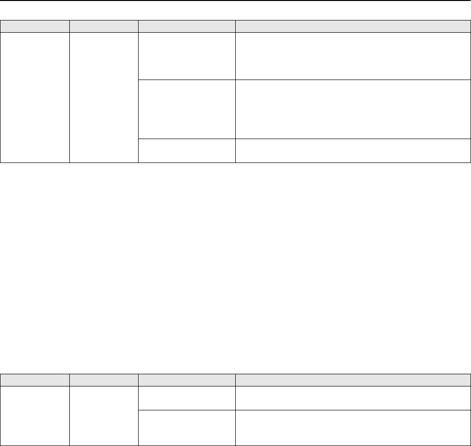
Dialog name Tab name Property item name Setting/Change/Point
◎Softkey number
Select the following number from the combo box:
0x0106 CREATION_CST_AUX (full key)-AUXILIARY
(16
i/18i/21i, Power Mate i)
0x3207 CUSTOM2-C Executor1(30
i, 31i, 32i)
◎Key Caption
Set a name, not longer than 6 letters, to be displayed on
the soft key caption indication area. In this example,
specify “CUSTOM”.
* When assignment to the CUSTOM key is made, this
caption is not soft key display on the CNC screen.
Setting user
screen
◎Select Flag
Check the check box to indicate that this user screen
setting is selected.
<5> In “Write to card and write to CNC/F-ROM”, screen data created
in MEM file generation and the MEM file of the FP driver
software for displaying the screen data are written to the F-ROM
on the CNC side.
Write the screen data and a copy of the FP driver to the
memory card.
Insert the memory card into the memory card slot of the
CNC (slot of the main CNC control unit when a display unit
with the display link connected is used, or slot on the side of
the display unit when a display unit of LCD-mounted type
or a display unit with HSSB connected is used) to start boot
processing.
Write the screen data and FP driver software to the F-ROM
by using the method of system data loading of the boot,
which is the same method as for writing PMC ladder data to
the F-ROM.
Dialog name Tab name Property item name Setting/Change/Point
◎Transfer to:
Specify the memory card drive of the personal computer
into which a write destination memory card is inserted.
Write to card
The FPdriver is
transferred to the
memory card.
The FP driver for the CNC model specified in the project
setting is automatically selected.
<6> Setting CNC parameters and S-RAM memory initialization alarm
screen
Set CNC parameters according to the table below.
If the FP driver software is first run on the CNC, an alarm
screen prompting the user to initialize the S-RAM area used
by the C language executor may be displayed when the
power is turned on.
If this alarm screen is displayed, check that the parameter
Nos. 8661, 8662, and 8781 are set to the values indicated in
the table below, then turn on the power again to initialize
the S-RAM area. This processing establishes a proper
environment to display the custom screen in the next
operation and afterward.
If you write the screen data and FP driver for the first time,
check that the parameters are set to the values indicated in
the table below even when the alarm screen is not
displayed.
Contents Summary of FANUC Picture Operators manual
- Page 1FANUC PICTURE OPERATOR’S MANUAL B-66284EN/01
- Page 2• No part of this manual may be reproduced in any form. • All specifications and designs are subject to change without notice. The export of this product is subject to the authorization of the government of the country from where the product is exported. In this manual we have tried as much as possi
- Page 3B-66284EN/01 SAFETY PRECAUTIONS SAFETY PRECAUTIONS This manual includes safety precautions for protecting the user and preventing damage to the machine. Precautions are classified into Warnings and Cautions according to their bearing on safety. Also, supplementary information is described as Notes.
- Page 4SAFETY PRECAUTIONS B-66284EN/01 1.1 WARNINGS AND NOTES RELATING TO FANUC PICTURE Warnings and notes relating to FANUC PICTURE are provided in this manual. Before using this software, read this manual thoroughly and read the Warnings, Cautions, and Notes in this manual carefully. In addition, "BE SUR
- Page 5B-66284EN/01 PRAFACE PREFACE Thank you for purchasing FANUC PICTURE. This software, FANUC PICTURE, is designed to help the user to easily create CNC screens on a personal computer. FANUC PICTURE runs on Microsoft® Windows2000®, and Microsoft® Windows XP®. Read this manual thoroughly for the proper p
- Page 6PRAFACE B-66284EN/01 1.1 FEATURES OF FANUC PICTURE FANUC PICTURE has the following features: Features • This software allows you to use a personal computer for designing CNC screens with a touch panel. CNC screens are displayed on the personal computer as if they were displayed on the CNC, so you ca
- Page 7B-66284EN/01 PRAFACE 1.2 CHECKING THE PRODUCT PACKAGE This product package consists of the following: • CD-ROM FANUC PICTURE disk (A08B-9010-J518#ZZ11) NOTE Be sure to read the release note (READMEE.TXT or READMEJ.TXT) on the first disk of this product package. The release note provides detailed inf
- Page 8PRAFACE B-66284EN/01 1.3 ORGANIZATION OF THIS MANUAL This manual is explained based on FANUC PICTURE Edition 1.04 (A08B-9010-J518#ZZ11). This manual is organized as follows: SAFETY PRECAUTIONS Describes general precautions that must be observed to ensure safety when using FANUC PICTURE . PREFACE Bri
- Page 9B-66284EN/01 PRAFACE 1.4 NOTATION CONVENTIONS IN THIS MANUAL This manual is described according to the following notation conventions: • Notations and operations of keys Notation example Explanation [Enter] key Key names are indicated in brackets [ ]. [Alt] + [→] key When two or more keys are held d
- Page 10
- Page 11B-66284EN/01 TABLE OF CONTENTS TABLE OF CONTENTS SAFETY PRECAUTIONS............................................................................s-1 PREFACE ....................................................................................................p-1 1 SETUP..................................
- Page 12TABLE OF CONTENTS B-66284EN/01 2.2.9.5 FP-PARAMETER SETTING screen................................................................. 53 2.2.10 Write to Card ..........................................................................................................55 2.2.11 Composite Forms ............
- Page 13B-66284EN/01 TABLE OF CONTENTS 2.4.1 Pointer Switching .................................................................................................253 2.4.2 Drawing of Line ...................................................................................................253 2.4.3 Drawing of Re
- Page 14TABLE OF CONTENTS B-66284EN/01 5 MEMORY SIZES OF CONTROLS AND RESTRICTIONS.................. 368 5.1 MEMORY SIZES OF CONTROLS ............................................................ 369 5.2 RESTRICTIONS,CAUTIONS..................................................................... 372 5.3 DIFFER
- Page 15B-66284EN/01 1.SETUP 1 SETUP This chapter describes the operating environment of FANUC PICTURE. This chapter also describes how to set up FANUC PICTURE. -1-
- Page 161.SETUP B-66284EN/01 1.1 OPERATING ENVIRONMENT The following operating environment is required to use this tool: Personal computer operating environment Personal computer : PentiumIII-500MHz or higher processor Basic software (OS) : Windows 2000 or Windows XP Application software : Internet Explorer
- Page 17B-66284EN/01 1.SETUP Setting NC parameters on the CNC To activate touch panel screens on the NC, set the following parameters: 8661 = 59 S-RAM variable area size (59K bytes) 8662 = 4 S-RAM file area size (4K bytes) 8781 = D-RAM size to be allocated to the C executor among the main CPU custom softwar
- Page 181.SETUP B-66284EN/01 1.2 INSTALLING FANUC PICTURE 1.2.1 INSTALLING FANUC PICTURE disk/ (A08B-9010-J518 #ZZ11) This section explains how to install FANUC PICTURE. Procedure Installation of FANUC PICTURE disk /(A08B-9010-J518 #ZZ11) 1. When the CD-ROM of the product is inserted into the CD-ROM drive,
- Page 19B-66284EN/01 1.SETUP 1.3 UNINSTALLING FANUC PICTURE This section explains how to uninstall FANUC PICTURE. When FANUC PICTURE is reinstalled, it is recommended that uninstallation be performed before setup operation is performed again. 1 Select [Start] → [Settings] → [Control Panel] → [Add/Remove Pro
- Page 202.DEVELOPMENT OF CUSTOM SCREEN B-66284EN/01 2 DEVELOPMENT OF CUSTOM SCREEN This chapter describes the method of activating and terminating FANUC PICTURE and the structure and function of each screen. -6-
- Page 21B-66284EN/01 2.DEVELOPMENT OF CUSTOM SCREEN 2.1 ACTIVATION AND TERMINATION This section describes the method of activating and terminating FANUC PICTURE . 2.1.1 Activating FANUC PICTURE This subsection describes the method of activating FANUC PICTURE . FANUC PICTURE is selected from the start menu o
- Page 222.DEVELOPMENT OF CUSTOM SCREEN B-66284EN/01 2.1.2 Terminating FANUC PICTURE This subsection describes the method of terminating FANUC PICTURE . Click the menu button EXIT or click in the title bar to terminate. -8-
- Page 23B-66284EN/01 2.DEVELOPMENT OF CUSTOM SCREEN 2.2 CONFIGURATIONS AND FUNCTIONS OF BARS 2.2.1 Menu Bar and Tool Bar of FANUC PICTURE This subsection describes the menu bar configuration and functions of FANUC PICTURE. When FANUC PICTURE is started, the screen shown below appears first. Menu bar Tool ba
- Page 242.DEVELOPMENT OF CUSTOM SCREEN B-66284EN/01 Item in the main menu Shortcut Icon in the Chapter of Functions * Sub menu key tool bar explanation Opens a custom screen according Screen ► Alt+S to the edit type. Opens a new custom screen form New Ctrl+N(N) as an editing target. Selects a custom screen
- Page 25B-66284EN/01 2.DEVELOPMENT OF CUSTOM SCREEN Item in the main menu Shortcut Icon in the Chapter of Functions * Sub menu key tool bar explanation Align ► Aligns the left side of the rectangle Left of each selected control with the left side of the reference control. Aligns the right side of the rectan
- Page 262.DEVELOPMENT OF CUSTOM SCREEN B-66284EN/01 Item in the main menu Shortcut Icon in the Chapter of Functions * Sub menu key tool bar explanation Chooses whether to display or hide Draw the draw bar. Chooses whether to set the grid interval function for setting a grid Grid interval that is used as the
- Page 27B-66284EN/01 2.DEVELOPMENT OF CUSTOM SCREEN Terminology: Project When an operator’s panel is created for a target machine with FANUC PICTURE (which may be hereinafter abbreviated as FP), a set of custom screens built into the machine is referred to as a project. The start folder for project creation
- Page 282.DEVELOPMENT OF CUSTOM SCREEN B-66284EN/01 2.2.2 FANUC PICTURE Tool Bar Controls and Draw Controls Under the tool bar, the FANUC PICTURE controls and draw controls are displayed. Each item of these bars can be displayed as an independent tool window. The tables below indicate the function of each c
- Page 29B-66284EN/01 2.DEVELOPMENT OF CUSTOM SCREEN Icon in the Chapter of Control Name Functions tool bar explanation Control for button operations for signal output and so 5 Button Control 2.3.6 forth Signal output button operation control with a lamp 6 Framed Button Control 2.3.7 function provided in the
- Page 302.DEVELOPMENT OF CUSTOM SCREEN B-66284EN/01 Icon in the Chapter of Control Name Functions tool bar explanation Control for displaying numerical data as a circle 21 Meter Control 2.3.22 meter or bar meter 22 Graph Control Control for displaying numerical data as a bar graph 2.3.23 Icon in the Chapter
- Page 31B-66284EN/01 2.DEVELOPMENT OF CUSTOM SCREEN 2.2.3 Symbol Specification with FANUC PICTURE With FANUC PICTURE, PMC signal addresses are used to create a custom screen. With the conventional specification method, absolute addresses such as R123.4 and D134 are used. With FANUC PICTURE of the new versio
- Page 322.DEVELOPMENT OF CUSTOM SCREEN B-66284EN/01 Deleting a symbol: Select a symbol name to be deleted, by left-clicking the mouse singly or when the Shift key or Ctrl key is held down, then click the Delete button. Import/Export: Each of the Import (Mnemonic/CSV) button and the Export (CSV) button displ
- Page 33B-66284EN/01 2.DEVELOPMENT OF CUSTOM SCREEN The method of symbol specification is described below. Absolute address specification Symbol specification Symbol: When you check the Symbol check box, the symbol specification method is selected for this PMC signal specification. Combo box for symbol spec
- Page 342.DEVELOPMENT OF CUSTOM SCREEN B-66284EN/01 2.2.4 Custom Screen Creation Procedure Start This flowchart indicates the procedure for creating a custom screen with FANUC PICTURE and the menu commands used. New New Existing Project? [File]Menu [Project]f[New] [File]Menu [Creating new project] [Project]
- Page 35B-66284EN/01 2.DEVELOPMENT OF CUSTOM SCREEN To create a custom screen with FANUC PICTURE, perform operations on the personal computer according to the flowchart shown on the previous page. Basically, proceed according to the procedure described below. Work on the personal computer <1> Create a proje
- Page 362.DEVELOPMENT OF CUSTOM SCREEN B-66284EN/01 2.2.5 Creating New Project Create a new project by using the procedure below. 1 Click New -Project on the file menu bar. 2 The dialog box for entering a project name appears. 3 Click … to display the Browse for Folder dialog box. 4 Select a folder to creat
- Page 37B-66284EN/01 2.DEVELOPMENT OF CUSTOM SCREEN 6 If, at this time, you want to create a new project for restoration from a backup of screen data for restoration sucked up from the F-ROM of the CNC control unit, check the Restoration from F-ROM check box. 7 Enter a desired project name, then click [OK].
- Page 382.DEVELOPMENT OF CUSTOM SCREEN B-66284EN/01 2.2.6 Open Project The menu item Open Project is used to modify a machine operation screen project currently being created or a machine operation screen project already created or to select a folder containing a project. Click Open - Project on the file me
- Page 39B-66284EN/01 2.DEVELOPMENT OF CUSTOM SCREEN 2.2.7 Setting of Project Set up the common items for the entire project. 2.2.7.1 Setting of CNC system Pressing the [Setting…] -[project]-[file menu bar] button causes the following dialog box to appear. For the items in the Setting of CNC system tab in th
- Page 402.DEVELOPMENT OF CUSTOM SCREEN B-66284EN/01 PMC type: Select the PMC type used in the target CNC system from the following: 3Xi(PMC for Series 30i) PMC/SB7 PMC/SB6 PMC/SB5 PMC/SD7 Display unit type Resolution: Choose whether the display unit of the target CNC is based on VGA (640×480 pixels) or XGA
- Page 41B-66284EN/01 2.DEVELOPMENT OF CUSTOM SCREEN CAN, INPUT, ALTER, INSERT, DELETE (editing keys) HELP key Any numeric key or alphanumeric character key (any of those keys enclosed in parentheses) can be used to call a pop-up screen for input. Numeric Indication Control with Key Input : Numeric Indicatio
- Page 422.DEVELOPMENT OF CUSTOM SCREEN B-66284EN/01 2.2.7.2 Setting of Multi-language Pressing the FANUC PICTURE menu bar [file]-[Project]-[Setting…] and clicking the [Setting of Multi-language] tab causes the Setting of Multi-language dialog box to appear. Make a setting to use the multi-language display f
- Page 43B-66284EN/01 2.DEVELOPMENT OF CUSTOM SCREEN The display language parameter of CNC is used. : Select this option button if the languages provided by the custom screen. • For Series 16i/18i/21i, Power Mate i The same parameter bits as the language bits of language parameters Nos. 3102 and 3119 of the
- Page 442.DEVELOPMENT OF CUSTOM SCREEN B-66284EN/01 2.2.7.3 Collection of history Pressing the FANUC PICTURE menu bar [File]-[Project]-[Setting…] and clicking the [Collection of history] tab causes the dialog box shown below to appear. The history message indication control of FANUC PICTURE can display a su
- Page 45B-66284EN/01 2.DEVELOPMENT OF CUSTOM SCREEN 4. Supports both number IF and bit I/F as the message indication interface (abbreviated I/F) for collecting history. For the number I/F, there may be up to 32 monitoring PMC areas; for the bit I/F, the monitoring PMC area may be of up to consecutive 512 bi
- Page 462.DEVELOPMENT OF CUSTOM SCREEN B-66284EN/01 NumberIF : Check this check box to use the number interface for the history message indication method. With the message using the number interface, up to 32 PMC indication request number specification areas with a length of either one or two bytes are prov
- Page 47B-66284EN/01 2.DEVELOPMENT OF CUSTOM SCREEN 2.2.8 Edit of Screen Form 2.2.8.1 Method of placing controls on a form 2 3 1 1. Click a desired control among the controls for FANUC PICTURE in the tool box of <1>. Only the controls provided by FANUC PICTURE can be used. 2. When the mouse pointer is moved
- Page 482.DEVELOPMENT OF CUSTOM SCREEN B-66284EN/01 2.2.8.2 Setting of properties To display the Property Pages dialog box (<3>), first place the mouse pointer on the control, then right-click. When the edit menu appears, select Properties... to display the dialog box. The Property Pages dialog box can also
- Page 49B-66284EN/01 2.DEVELOPMENT OF CUSTOM SCREEN 2.2.8.4 Pop-up menu display When you right-click the mouse on a screen form, the pup menu appears as shown below. This pop-up menu enables an editing operation to be performed quickly on the currently selected control. 2.2.8.5 Mouse operation and key opera
- Page 502.DEVELOPMENT OF CUSTOM SCREEN B-66284EN/01 Mouse and key Edit operation Explanation operation Change in group selection standard When pressing an arrow key with a group selected, the Arrow key control standard control can be changed. Movement of control When pressing the left button to select a con
- Page 51B-66284EN/01 2.DEVELOPMENT OF CUSTOM SCREEN 2.2.9 Make MEM file This step converts data to display a created machine operation screen with FANUC PICTURE on the CNC and creates an MEM file to be written to the F-ROM of the CNC. By using the procedure below, convert a created custom screen to screen d
- Page 522.DEVELOPMENT OF CUSTOM SCREEN B-66284EN/01 <4> In the Screen Number pull-down list box, specify a CNC screen to be replaced. For a screen number with the “C Executor” comment, the screen displayed on the CNC remains to be unchanged, and a free screen soft key is assigned. (For CNC units and availab
- Page 53B-66284EN/01 2.DEVELOPMENT OF CUSTOM SCREEN <8> Click OK to return to the Making of memory card file dialog box. Click OK in the Making of memory card file dialog box to create data in memory card format. When the memory card format file FPF0FPDT.mem or CEX0FPDT.mem is created, the dialog box indica
- Page 542.DEVELOPMENT OF CUSTOM SCREEN B-66284EN/01 2.2.9.2 Switching between the CNC screen and custom screen Explained below are how a custom screen created using FANUC PICTURE is called from the CNC display unit and how switching occurs from the custom screen to a CNC-provided screen. The following two m
- Page 55B-66284EN/01 2.DEVELOPMENT OF CUSTOM SCREEN Cautions Each CNC function key remembers a subscreen previously displayed with it. When a function key other than the currently active function key is pressed, the subscreen previously displayed with the pressed function key appears. A concrete example fol
- Page 562.DEVELOPMENT OF CUSTOM SCREEN B-66284EN/01 2.2.9.3 Settings for calling a custom screen with the OPER/CUSTOM/GRAPH keys This subsection explains the method of calling a custom screen with the [OPER]/[CUSTOM] keys on the virtual keyboard and the [CUSTOM] key on the MDI unit of the Series 16i/18i/21i
- Page 57B-66284EN/01 2.DEVELOPMENT OF CUSTOM SCREEN • Select the same soft key number as that determined according to the table above from [Softkey Number] in the Setting user screen dialog box shown in Subsection 2.2.9.1. NOTE 1 • Of the three parameter bits, set only one to 1 and assign the soft key numbe
- Page 582.DEVELOPMENT OF CUSTOM SCREEN B-66284EN/01 2.2.9.4 Option function details setting Click the Detail button to display the following dialog box. This dialog box is used to specify the various settings for the function for automatically calling screens from the PMC and the function for reporting the
- Page 59B-66284EN/01 2.DEVELOPMENT OF CUSTOM SCREEN The automatic screen call is used.: Check this check box to use the function for automatically calling screens from the PMC. Request Signal Area: Specify the type of the PMC address of the signal conveying a request to call a screen from the PMC to the tou
- Page 602.DEVELOPMENT OF CUSTOM SCREEN B-66284EN/01 Change Signal Address: Specify the address of the change signal. Change Signal Bit: Specify the bit position of the signal address above by using a number 0 to 7. The screen number notification is used: Check this check box to use the function by which the
- Page 61B-66284EN/01 2.DEVELOPMENT OF CUSTOM SCREEN (2) Display Number Setting Using the function for automatically calling screens from the PMC or the function for reporting the number of the screen currently displayed on the touch panel operator’s panel requires that screen numbers be allocated to automat
- Page 622.DEVELOPMENT OF CUSTOM SCREEN B-66284EN/01 (3) Each Display Setting This menu item allows you to specify whether to free memory for those screens that cannot be set using the screen structure definition control. It does not allow you to change the specification as to whether to free memory for thos
- Page 63B-66284EN/01 2.DEVELOPMENT OF CUSTOM SCREEN (4) Signal Display/OP ratio The signal display function displays signal information set in the button control (Only the one that the shortcut key is defined can be displayed for non-touch panel display unit) and the lamp control (The lamp cannot be display
- Page 642.DEVELOPMENT OF CUSTOM SCREEN B-66284EN/01 The signal display is used : Check this check box to use the function for Signal display. Change Signal Area: Specify the type of the PMC address of the change signal which displays pop-up window to display signal. Change Signal Address: Specify the addres
- Page 65B-66284EN/01 2.DEVELOPMENT OF CUSTOM SCREEN • Configuration of the interface area for operation ratio change #7 #6 #5 #4 #3 #2 #1 #0 Custom By using seven bits from #0 to #6, specify the operation time ratio between the display of screen ratio custom screens created with FANUC PICTURE and the proces
- Page 662.DEVELOPMENT OF CUSTOM SCREEN B-66284EN/01 (5) Buzzer Signal Setting If a touch operation is performed while a custom screen created with FANUC PICTURE is displayed, the touch operation can be output to the PMC signal area. With this output signal, for example, the external buzzer can be sounded. H
- Page 67B-66284EN/01 2.DEVELOPMENT OF CUSTOM SCREEN 2.2.9.5 FP-PARAMETER SETTING screen When the operator’s panel screen created in FANUC PICTURE is displayed on the CNC, each type of control can operate in a different way. The operations can be controlled by setting the parameters on the [FP-PARAMETER SETT
- Page 682.DEVELOPMENT OF CUSTOM SCREEN B-66284EN/01 OK Button To save the parameters specified on the [FP-PARAMETER SETTING] screen and then exit the screen, click the OK button. Cancel button To clear the parameters specified on the [FP-PARAMETER SETTING] screen and then exit the screen, click the [Cancel]
- Page 69B-66284EN/01 2.DEVELOPMENT OF CUSTOM SCREEN 2.2.10 Write to Card Using the procedure described below, operator’s panel screen data (such as FPF0FPDT.MEM or CEX0FPDT.MEM) and the FP driver are copied to the memory card. Clicking Output MEM File on the menu displays the Write to card dialog box. The f
- Page 702.DEVELOPMENT OF CUSTOM SCREEN B-66284EN/01 Download from the memory card to F-ROM of the CNC Operator’s panel data (FPF0FPDT.MEM or CEX0FPDT.MEM) or the FP driver can be downloaded to the F-ROM of the CNC by using the boot function of the CNC. For the method of activating the boot function, refer t
- Page 71B-66284EN/01 2.DEVELOPMENT OF CUSTOM SCREEN The screen names serve as the names for screens created under a project. As sub(child) screen names 1 through 5, sub(child) screen names specified in the base(main/parent) screen are indicated. If the screen switch button can be used for switching from one
- Page 722.DEVELOPMENT OF CUSTOM SCREEN B-66284EN/01 2.2.12 Option FANUC PICTURE allows you to set the operating environment for creating an operator's screen, optionally. 2.2.12.1 Color The type of the color depth used on the screen can be selected. Compatible: The same depth colors as with the former FANUC
- Page 73B-66284EN/01 2.DEVELOPMENT OF CUSTOM SCREEN 2.3 CONTROLS 2.3.1 Procedure for Setting Properties Common to Controls 2.3.1.1 Description of general property setting items OK button This button validates property settings and quits the dialog box. Cancel button This button cancels the currently open pr
- Page 742.DEVELOPMENT OF CUSTOM SCREEN B-66284EN/01 Coordinate specification A position on the screen is represented by two-dimensional (0,0) coordinates (X,Y) with the upper-left corner of the screen set as the origin (0,0). (See the figure at left.) The following indicates the X coordinate specifiable ran
- Page 75B-66284EN/01 2.DEVELOPMENT OF CUSTOM SCREEN On Caption is copied onto Off Caption The following controls, which have both On and Off captions, have a caption copy check box: Screen switch control Lamp control Button control Framed button control Checking this check box causes the On caption settings
- Page 762.DEVELOPMENT OF CUSTOM SCREEN B-66284EN/01 Character Type The following table shows the characters displayable for each character type and their display sizes in the cases where the number of soft keys is 5 + 2 and 10 + 2 (including the cases where a touch panel is used). Half-size (width : height)
- Page 77B-66284EN/01 2.DEVELOPMENT OF CUSTOM SCREEN Editing multi-language display captions The following explains how to edit the On and Off captions of buttons and lamps in each language. The setting operation explained below is possible if The Multi-Language display function is used. is checked in the [S
- Page 782.DEVELOPMENT OF CUSTOM SCREEN B-66284EN/01 In a tab having captions, a property for multi-language input is provided, such as that shown in <1> in the above figure. The basic operation is to select the multi-language key to be set for a caption from the [Multi-language key] combo box and enter char
- Page 79B-66284EN/01 2.DEVELOPMENT OF CUSTOM SCREEN Color specification Clicking a color button … on the Image tab opens the Color dialog box. In this dialog box, select a desired color, then click OK to set a color property. On the LCD on the CNC, a color closest to a specified color is displayed. - 65 -
- Page 802.DEVELOPMENT OF CUSTOM SCREEN B-66284EN/01 2.3.1.2 Editing text message files Structure of a text file and editing it A text file has a spreadsheet structure such as that shown below. Number: If using numbers as the interface with the PMC, enter the text number. If this number is written to the num
- Page 81B-66284EN/01 2.DEVELOPMENT OF CUSTOM SCREEN Insert Row : When a certain cell is selected entirely, moving the cursor to the position at which rows are to be inserted and clicking the Insert Row button causes the Number Setting dialog box to appear; enter the number of rows to be inserted. The specif
- Page 822.DEVELOPMENT OF CUSTOM SCREEN B-66284EN/01 Check Char : This option checks the message text on all lines to see if the set message character string contains characters that cannot be displayed with the character type of the character property of the control. OK : Terminates editing. Clicking it cau
- Page 83B-66284EN/01 2.DEVELOPMENT OF CUSTOM SCREEN If you start editing of new text message file when The Multi-language display function is used. is checked in [Setting of project]-[Setting of Multi-language], the file type selection dialog box shown in the figure above appears. Select the desired type an
- Page 842.DEVELOPMENT OF CUSTOM SCREEN B-66284EN/01 Rename sheet name button : If, after adding a multi-language message sheet, you rename a multi-language key with [Setting of project], you must change the old sheet name to the same name as the new multi-language sheet name. Select the tab of the sheet you
- Page 85B-66284EN/01 2.DEVELOPMENT OF CUSTOM SCREEN Delete sheet button : This button deletes an unnecessary sheet. Select the tab of the sheet you want to delete by clicking it. Then, press the Delete sheet button. The dialog box for confirming deletion appears. Click either the OK or Cancel button. No use
- Page 862.DEVELOPMENT OF CUSTOM SCREEN B-66284EN/01 2.3.1.3 Creating custom screens for non-touch panel display units Using FANUC PICTURE lets you create custom screens used on non-touch panel display units. The display units must be provided with graphic functions. When creating a custom screen, you specif
- Page 87B-66284EN/01 2.DEVELOPMENT OF CUSTOM SCREEN Term Explanation This term collectively refers to the following controls: 1. Numeral Indication control with Key Input Control with input 2. Numeral Indication control for Calling a Ten-Key Pad 3. PMC Area character string Indication control This term pert
- Page 882.DEVELOPMENT OF CUSTOM SCREEN B-66284EN/01 custom screen. After this, the focus moves in the direction corresponding to any pressed cursor key according to the common focus movement rule for the screen and the direct-specification focus movement rule. If the focus is on a control having the highest
- Page 89B-66284EN/01 2.DEVELOPMENT OF CUSTOM SCREEN CAUTION When using a pop-up screen to input data for a control with input, observe the following: 1. To perform continuous input, specify a pop-up main screen name for data input as a “Pop-up screen name” property. 2. Be sure to place a pop-up erase button
- Page 902.DEVELOPMENT OF CUSTOM SCREEN B-66284EN/01 Shortcut key property A “Shortcut key” property has been added to the Action tab for the following button/switch controls. 1. Screen Switch control 2. Button Control 3. Framed Button Control Shortcut key : If you want to execute an operation set up on the
- Page 91B-66284EN/01 2.DEVELOPMENT OF CUSTOM SCREEN The figure below shows the soft key name and the position in case of 5+2 soft keys. LCD FL F1 F2 F3 F4 F5 FR The figure below shows the soft key name and the position in case of 10+2,or 10+2+9 soft keys. VF1 VF2 VF3 VF4 VF5 LCD VF6 VF7 VF8 VF9 FL F1 F2 F3
- Page 922.DEVELOPMENT OF CUSTOM SCREEN B-66284EN/01 Control with additional focus-related properties To the following indication controls, a focus tab is added: 1. Numeral Indication Control with Key Input 2. Numeral Indication Control for Calling a Ten-Key Pad 3. PMC Area Character String Indication Contro
- Page 93B-66284EN/01 2.DEVELOPMENT OF CUSTOM SCREEN Use TabIndex property for focusing index: This setting cannot be used at present. CAUTION 1 If “Specify the focusing index” is selected, do not use the same number for two or more focusing indexes within one screen (form). 2 For both Focusing index and Tab
- Page 942.DEVELOPMENT OF CUSTOM SCREEN B-66284EN/01 Focus rule tab of Screen Set control The property dialog of the Screen Set Control in the background of the screen form is displayed, and set up the property on the Focus rule tab. On this tab, it is possible to specify whether to enable or disable the com
- Page 95B-66284EN/01 2.DEVELOPMENT OF CUSTOM SCREEN Common focus movement rule UP key, DOWN key, LEFT key, RIGHT key : Set up a common focus movement rule for controls with input placed on a screen. To be specific, specify index increment/decrement values to be added to the focusing index number for a contr
- Page 962.DEVELOPMENT OF CUSTOM SCREEN B-66284EN/01 Focus Movement & Continuous Input setting example (Focus movement specification example 1): 1 6 11 16 2 7 12 17 3 8 13 18 4 9 14 19 5 10 15 20 The screen has 5 rows × 4 columns of controls placed as shown at the left. Pressing the ↓ cursor key moves the fo
- Page 97B-66284EN/01 2.DEVELOPMENT OF CUSTOM SCREEN (Focus movement specification example 2): The focus is moved in the same manner as in example 1 above. However, to specify the direction of continuous inputs as horizontal like 1 → 6 → 11 → 16 → 2 → . . . → 20 → disable, set up the screen set control as li
- Page 982.DEVELOPMENT OF CUSTOM SCREEN B-66284EN/01 Example of specifying properties on the Focus rule tab of the Screen Set control Common focus movement rule Direction(for Continuous input) Continuous input key key 1 3 Example of setting up properties on the Focus tab for controls with input Focus index
- Page 99B-66284EN/01 2.DEVELOPMENT OF CUSTOM SCREEN MDI key Control Operating function Touch panel operation operation Causes the input screen to appear. Touch the target control. Any key Any of the four Display the focus. (No operation) cursor key Control with input Any of the four (By pop-up Ten-Key) Move
- Page 1002.DEVELOPMENT OF CUSTOM SCREEN B-66284EN/01 2.3.1.6 Creating screens with the multi-language display function The multi-language display function can be built into the operation board. As for this function, the caption on the custom screen is switched to the language of 20 countries. Creating a cust
- Page 101B-66284EN/01 2.DEVELOPMENT OF CUSTOM SCREEN (1) Setting up the multi-language display function The following explains the setting operation for making a custom screen project support the multi-language display function. - Setting of project-Setting of Multi-language Pressing the FANUC PICTURE menu b
- Page 1022.DEVELOPMENT OF CUSTOM SCREEN B-66284EN/01 Method of switching Multi-language display For this item, select between the two types described below as the method of switching display languages on the CNC display unit. The display language parameter of CNC is used. : Select this option button if the l
- Page 103B-66284EN/01 2.DEVELOPMENT OF CUSTOM SCREEN - Registering, deleting, and editing language keys Register the “Multi-language key” of the language to be created using the frame in the dialog box shown below. You can check the entire comment by using the horizontal scroll bar. For each language provide
- Page 1042.DEVELOPMENT OF CUSTOM SCREEN B-66284EN/01 Language key editing Double-clicking a 2-digit numeric value in the [No.] column in the language key list display (such a number is called an item number in the remainder of this document) causes the Language change setting dialog box to appear, which is t
- Page 105B-66284EN/01 2.DEVELOPMENT OF CUSTOM SCREEN Param bit : If you select "The display language parameter of CNC is used" as the display language switching interface, set the parameter bit number specified under [Param No.]. • Series 16i/18i/21i, Power Mate i Generally, specify the bit of the correspond
- Page 1062.DEVELOPMENT OF CUSTOM SCREEN B-66284EN/01 2.3.1.7 Setting the signal for the PMC/SD7 type If you set SD7 for PMC type in [File]-[Project]-[Setting…]-[Setting of CNC system] tab, the signal setting properties of various dialog boxes will set SD7 notation signals using area and address properties. A
- Page 107B-66284EN/01 2.DEVELOPMENT OF CUSTOM SCREEN Table of correspondence between the PMC signal area combo box, FP function argument numbers, and signal areas Combo box list for selecting PMC FP-function-specification-time area Item Argument signal area selection argument Number Number SB7 SD7 SB7 SD7 0
- Page 1082.DEVELOPMENT OF CUSTOM SCREEN B-66284EN/01 2.3.2 Screen Set Control Screen Set control is a control to do various setting of the screen. This control is a control to set necessary information at MEM make. This control is not displayed on the CNC screen. Only a single instance of this control can be
- Page 109B-66284EN/01 2.DEVELOPMENT OF CUSTOM SCREEN Property Pages - General Object ID: Object ID managed in the form. This ID is automatically assigned. The user cannot change this ID. X,Y: Set the coordinates of the upper-left corner of the screen set control. This control is not displayed on the CNC scre
- Page 1102.DEVELOPMENT OF CUSTOM SCREEN B-66284EN/01 - Option Use signal of notice screen display: Check this box to output PMC signals when this screen is displayed. Out PMC Area: Select a type of PMC address where a signal is output. Out PMC Address: Specify a PMC address where a signal is output. Out PMC
- Page 111B-66284EN/01 2.DEVELOPMENT OF CUSTOM SCREEN - Focus rule Common focus movement rule UP key, DOWN key, LEFT key, RIGHT key: Set up a common focus movement rule for controls with input placed on a screen. To be specific, specify index increment/decrement values to be added to the focusing index number
- Page 1122.DEVELOPMENT OF CUSTOM SCREEN B-66284EN/01 2.3.3 Screen Structure Definition Control The screen structure definition control provides two types of specification: setting of a combination of sub screens to make up a single screen (base screen) and definition of a popup screen. Only a single instance
- Page 113B-66284EN/01 2.DEVELOPMENT OF CUSTOM SCREEN A popup screen with up to two layers can be displayed. If a popup screen is displayed, only the screen displayed last will be active. This means that the background screen terminates and buttons and the like will not respond when touched. Data Change Repor
- Page 1142.DEVELOPMENT OF CUSTOM SCREEN B-66284EN/01
• The base screen that uses this change report area is displayed. • A change report control other than the change report control that has reported a change is brought into focus (the focus is shifted to another control). One or more change - Page 115B-66284EN/01 2.DEVELOPMENT OF CUSTOM SCREEN Popup screen to be called from a base screen A popup screen may also have a change report area. If a popup screen does not use a change report area, it reports the data change state using the change report area of the base screen from which the popup scree
- Page 1162.DEVELOPMENT OF CUSTOM SCREEN B-66284EN/01 - Base screen Screen Name: Set the name of the form file where this component is placed. Free Memory: For high-speed screen display, screen data once read is stored in the memory inside the touch panel. However, the memory space is limited. If you check th
- Page 117B-66284EN/01 2.DEVELOPMENT OF CUSTOM SCREEN - Sub screen The procedure for setting the properties below applies to sub screen 1 through sub screen 5. Use SubScreen n: Check this box when using the property settings for sub screen n. Save SubScreen n: When this base screen is selected and displayed o
- Page 1182.DEVELOPMENT OF CUSTOM SCREEN B-66284EN/01 - Options Use Signal of Update notification: Check this check box to use the function to notify the PMC that data is updated by the control change function, which was described earlier. The function is used when a change report control having a numeric val
- Page 119B-66284EN/01 2.DEVELOPMENT OF CUSTOM SCREEN 2.3.4 Screen Switch Control This control is used to switch from one screen to another. Touching the screen switch control on the screen switches the screen display to the screen set as a property of this control. Following types of screen switch operations
- Page 1202.DEVELOPMENT OF CUSTOM SCREEN B-66284EN/01 (2) Embedded-plug-style indication by an invalid signal When the invalid signal specified during power-up is turned on, the embedded-plug-style indication is used. The state of the invalid signal is obtained during power-up. Therefore, even if the state is
- Page 121B-66284EN/01 2.DEVELOPMENT OF CUSTOM SCREEN Property Pages - General Object ID: Object ID managed in the form. This ID is automatically assigned. The user cannot change this ID. X, Y: Set the coordinates of the upper-left corner of the screen switch control. Width, Height: Set the width and height o
- Page 1222.DEVELOPMENT OF CUSTOM SCREEN B-66284EN/01 - Character No use multi-language: Multi-language key: See [Editing multi-language display captions] in Subsection 2.3.1.1, “Description of general property setting items”. Centering: Check this check box to center the caption display position automaticall
- Page 123B-66284EN/01 2.DEVELOPMENT OF CUSTOM SCREEN X, Y: Specify the display position of the caption by using relative coordinates within the rectangle of the control. With the upper-left corner of the rectangle of the control used as the reference, specify the coordinates of the upper-left corner of the c
- Page 1242.DEVELOPMENT OF CUSTOM SCREEN B-66284EN/01 - Action No Action: Check this check box to disable the screen switch control function. The control can be placed on the form, but can be disabled, in which case the display is embedded. Set the embedded image for no action set in the Image tab. Screen Typ
- Page 125B-66284EN/01 2.DEVELOPMENT OF CUSTOM SCREEN Shortcut key: If you want to execute an operation set up on the Action tab by pressing an associated shortcut key, turn on this check box. An operation associated to the shortcut key setting can be executed by pressing the key on the display unit, no matte
- Page 1262.DEVELOPMENT OF CUSTOM SCREEN B-66284EN/01 - Image Mask Image File: The FIG file holding the button figures to be used when the No Action check box in the Action tab is checked can be selected. Mask Style: Select a type of button figure registered in Mask Image File. Image File Name: The FIG file h
- Page 127B-66284EN/01 2.DEVELOPMENT OF CUSTOM SCREEN - NoAction Image This tab is valid when [NoAction] on the [Action] tab is checked. NoAction Signal: Check this check box to use the embedded-plug-style indication by an invalid signal. This function disables the function of the screen switching control and
- Page 1282.DEVELOPMENT OF CUSTOM SCREEN B-66284EN/01 Bit: Specify the bit position (between 0 and 7) of the above signal address. Preview: Check this check box to confirm the indication state on the form when the button control is in the invalid state. This property is valid for the form display on a PC. Thi
- Page 129B-66284EN/01 2.DEVELOPMENT OF CUSTOM SCREEN - Interlock Image This tab is valid when [Interlock] on the [Action] tab is checked. Display: Check this check box to change the style indication of an interlocked button. When [Interlock Signal] on the [Action] tab is set to ON, the function of the screen
- Page 1302.DEVELOPMENT OF CUSTOM SCREEN B-66284EN/01 2.3.5 Lamp Control This control is used as a lamp whose light section color and caption change according to the state of an input signal from the PMC. Property Pages - General Object ID: Object ID managed in the form. This ID is automatically assigned. The
- Page 131B-66284EN/01 2.DEVELOPMENT OF CUSTOM SCREEN - Character No use multi-language: Multi-language key: See [Editing multi-language display captions] in Subsection 2.3.1.1, “Description of general property setting items”. Centering: Check this check box to center the caption display position automaticall
- Page 1322.DEVELOPMENT OF CUSTOM SCREEN B-66284EN/01 X, Y: Specify the display position of the caption by using relative coordinates within the rectangle of the control. Specify the coordinates of the upper-left corner of the character string to be displayed. If you have checked the check box for automatic c
- Page 133B-66284EN/01 2.DEVELOPMENT OF CUSTOM SCREEN - Action No Action: Check this check box to disable the lamp control function. The control can be placed on the form, but can be disabled, in which case the display is embedded. Set the lamp image for no action set in the Image tab. Watch PMC Area: Specify
- Page 1342.DEVELOPMENT OF CUSTOM SCREEN B-66284EN/01 - Image Mask Image File: The FIG file holding the lamp figures to be used when the No Action check box in the Action tab is checked can be selected. Mask Style: Select a type of lamp figure registered in Mask Image File. Image File Name: The FIG file holdi
- Page 135B-66284EN/01 2.DEVELOPMENT OF CUSTOM SCREEN - Option Use 7 Colors: Check this box to use seven colors as the background colors of the numeral indication section. Type: Specify how to switch seven colors. 0:PMC (bit) Allows you to switch the background color at the bit position of the PMC area specif
- Page 1362.DEVELOPMENT OF CUSTOM SCREEN B-66284EN/01 Data Length: If specifying 1:PMC (big or small comparison) for Type, specify the data length of the PMC area specified with the signal area and the signal address. 0: 1 Byte (Signed) 1: 1 Byte (Unsigned) 2: 2 Byte (Signed) 3: 2 Byte (Unsigned) 4: 4 Byte (S
- Page 137B-66284EN/01 2.DEVELOPMENT OF CUSTOM SCREEN - NoAction Image This tab is valid when [NoAction] on the [Action] tab is checked. NoAction Signal: Check this check box to use the embedded-plug-style indication by an invalid signal. This function disables the function of the screen switching control and
- Page 1382.DEVELOPMENT OF CUSTOM SCREEN B-66284EN/01 Preview: Check this check box to confirm the indication state on the form when the button control is in the invalid state. This property is valid for the form display on a PC. This property does not affect the screen display of the CNC - 124 -
- Page 139B-66284EN/01 2.DEVELOPMENT OF CUSTOM SCREEN 2.3.6 Button Control This control consists of a lamp section whose light section color and caption change according to the state of an input signal from the PMC, and a switch section that performs the following operations when the button section is pressed
- Page 1402.DEVELOPMENT OF CUSTOM SCREEN B-66284EN/01 (3) Interlocking-style indication The button style indication during input of the interlock signal helps the operator visually check the state of the button by displaying the style that indicates the interlocking state. Since both the interlocking style an
- Page 141B-66284EN/01 2.DEVELOPMENT OF CUSTOM SCREEN Property Pages - General Object ID: Object ID managed in the form. This ID is automatically assigned. The user cannot change this ID. X, Y: Set the coordinates of the upper-left corner of the button control. Width, Height: Set the width and height of the b
- Page 1422.DEVELOPMENT OF CUSTOM SCREEN B-66284EN/01 - Character No use multi-language: Multi-language key: See [Editing multi-language display captions] in Subsection 2.3.1.1, “Description of general property setting items”. Centering: Check this check box to center the caption display position automaticall
- Page 143B-66284EN/01 2.DEVELOPMENT OF CUSTOM SCREEN OFF Caption: Set a character string to be output to the light section when the PMC monitor signal is off. Line continuation can be performed as with an ON caption. X, Y: Specify the display position of the OFF caption by using relative coordinates within t
- Page 1442.DEVELOPMENT OF CUSTOM SCREEN B-66284EN/01 - Action NoAction: Check this check box to disable the button control function. The control can be placed on the form, but can be disabled, in which case the display is embedded. Set the button image for no action set in the Image tab. Switch Type: Select
- Page 145B-66284EN/01 2.DEVELOPMENT OF CUSTOM SCREEN Shortcut key: If you want to execute an operation set up on the Action tab by pressing an associated shortcut key, turn on this check box. An operation associated to the shortcut key setting can be executed by pressing the key on the display unit, no matte
- Page 1462.DEVELOPMENT OF CUSTOM SCREEN B-66284EN/01 Action Detail Properties - Detail[Momentary]-[Bit Set] Specify which data to be output to which signal bit when the switch is on. PMC Area: Specify a type of address for a PMC signal to be output. The following areas can be specified: R, D, K, X, Y, G, F,
- Page 147B-66284EN/01 2.DEVELOPMENT OF CUSTOM SCREEN Address: Specify an output signal address. Bit: Specify the bit position of the signal above by using a number from 0 to 7. Bit Pattern: [0:0] Outputs 0 (LOW) to a bit specified for output. [1:1] Outputs 1 (HIGH) to a bit specified for output. [2:Revers] O
- Page 1482.DEVELOPMENT OF CUSTOM SCREEN B-66284EN/01 Address: Specify an output signal address. Word: Specify a value from -32767 to +32767. - Detail[Momentary]-[Function Call] Specify a function to be called when the switch is turned on. Function: Describe an FP function. For the method of description, see
- Page 149B-66284EN/01 2.DEVELOPMENT OF CUSTOM SCREEN - Detail[Change Screen] Specify a main screen to be called when the switch is turned on. Screen Name: Specify a main screen name. For a screen name, enter the XXX portion of the project form file name XXX.XML. - Detail[Momentary]-[History Display] You can
- Page 1502.DEVELOPMENT OF CUSTOM SCREEN B-66284EN/01 <3> Page Switch Button This item creates a Page Switch Button for a summary display or history display message. If selecting this operation, set the following properties: • Link Number at output button • MDI Key Code Link Number at output button: Specify t
- Page 151B-66284EN/01 2.DEVELOPMENT OF CUSTOM SCREEN - Detail [Alternate]-[History Display] [ON Action], [OFF Action] Under [ON Action] and [OFF Action], specify separately the history message indication control operations to be executed when the button changes from the off state to the on state and from on
- Page 1522.DEVELOPMENT OF CUSTOM SCREEN B-66284EN/01 - Image Mask Image File: The FIG file holding the button figures to be used when the No Action check box in the Action tab is checked can be selected. Style: Select a type of button figure registered in Mask Image File. Image File Name: The FIG file holdin
- Page 153B-66284EN/01 2.DEVELOPMENT OF CUSTOM SCREEN - NoAction Image This tab is valid when [NoAction] on the [Action] tab is checked. NoAction signal: Check this check box to use the embedded-plug-style indication by an invalid signal. This function disables the function of the button control and displays
- Page 1542.DEVELOPMENT OF CUSTOM SCREEN B-66284EN/01 Preview: Check this check box to confirm the indication state on the form when the button control is in the invalid state. This property is valid for the form display on a PC. This property does not affect the screen display of the CNC - 140 -
- Page 155B-66284EN/01 2.DEVELOPMENT OF CUSTOM SCREEN - Interlock Image This tab is valid when [Interlock] on the [Action] tab is checked. Display: Check this check box to change the style indication of an interlocked button. When [Interlock Signal] on the [Action] tab is set to ON, the function of the button
- Page 1562.DEVELOPMENT OF CUSTOM SCREEN B-66284EN/01 2.3.7 Framed Button Control This control consists of a lamp section whose light section color and caption change according to the state of an input signal from the PMC, a switch section that sets a specified PMC signal to on when the button section is pres
- Page 157B-66284EN/01 2.DEVELOPMENT OF CUSTOM SCREEN (3) Interlocking-style indication The button style indication during input of the interlock1 signal helps the operator visually check the state of the button by displaying the style that indicates the interlocking state. Since both the interlocking style a
- Page 1582.DEVELOPMENT OF CUSTOM SCREEN B-66284EN/01 [3:Momentary(Use Lamp)] This type of switch is on while the button is held down, and is off when the button is released. Depending on the switch state, the on (1) or off (0) signal is output to an address. Display operation depends on the following: Switch
- Page 159B-66284EN/01 2.DEVELOPMENT OF CUSTOM SCREEN When switching to another screen, the user can choose whether to turn off the switch or preserve the current state. The operation is as follows: Switch state OFF ON Lamp light signal OFF ON OFF ON Frame color Frame off color Frame on color Frame on color F
- Page 1602.DEVELOPMENT OF CUSTOM SCREEN B-66284EN/01 - Character No use multi-language: Multi-language key: See [Editing multi-language display captions] in Subsection 2.3.1.1, “Description of general property setting items”. Centering: Check this check box to center the caption display position automaticall
- Page 161B-66284EN/01 2.DEVELOPMENT OF CUSTOM SCREEN X, Y: Specify the display position of the caption by using relative coordinates within the rectangle of the control. Specify the coordinates of the upper-left corner of the character string to be displayed. If you have checked the check box for automatic c
- Page 1622.DEVELOPMENT OF CUSTOM SCREEN B-66284EN/01 - Action No Action: Check this check box to disable the function of the framed button control. The control can be placed on the form, but can be disabled, in which case the display is embedded. Set the image for no action set in the Image tab. Keep State:
- Page 163B-66284EN/01 2.DEVELOPMENT OF CUSTOM SCREEN Group No: A group number can be specified when the actuator button or alternate button is selected. A button with the same group number operates as a selector switch. In selector switch operation, only one switch operates in one group; if another switch is
- Page 1642.DEVELOPMENT OF CUSTOM SCREEN B-66284EN/01 Light PMC (Light PMC Area, Light PMC Address, Light PMC Bit): These items can be specified when the momentary button (with a lamp), actuator button, or alternate button is selected. Specify a signal for turning on the lamp section. Specify these items in t
- Page 165B-66284EN/01 2.DEVELOPMENT OF CUSTOM SCREEN - Image Mask Image File: The FIG file holding the button figures to be used when the No Action check box in the Action tab is checked can be selected. Mask Style: Select a type of button figure registered in Mask Image File. Image File Name: The FIG file h
- Page 1662.DEVELOPMENT OF CUSTOM SCREEN B-66284EN/01 Border On Color: For a framed figure button, select a button frame ON color. For other types of buttons, select a frame color for the lower edge and right edge. On Preview: Check this check box to confirm the display state on the form when the button is tu
- Page 167B-66284EN/01 2.DEVELOPMENT OF CUSTOM SCREEN - NoAction Image This tab is valid when [No Action] on the [Action] tab is checked. No Action Signal: Check this check box to use the embedded-plug-style indication by an invalid signal. This function disables the function of the bordered button control an
- Page 1682.DEVELOPMENT OF CUSTOM SCREEN B-66284EN/01 PMC Area: Specify the type of the PMC address of the invalid signal. The following areas can be specified. R, D, K, X, Y, G, F, E(PMC-SB7) Address: Specify the PMC address of the invalid signal. Bit: Specify the bit position (between 0 and 7) of the above
- Page 169B-66284EN/01 2.DEVELOPMENT OF CUSTOM SCREEN - Interlock Image This tab is valid when [Interlock1] on the [Action] tab is checked. Display: Check this check box to change the style indication of an interlocked button. When [Interlock Signal] on the [Action] tab is set to ON, the function of the borde
- Page 1702.DEVELOPMENT OF CUSTOM SCREEN B-66284EN/01 Border Color2: Select the color of the lower and right ends of the button. Preview: Check this check box to confirm the indication state on the form when the bordered button control is in the stopped state. This property is valid for the form display on a
- Page 171B-66284EN/01 2.DEVELOPMENT OF CUSTOM SCREEN 2.3.8 MDI Key Control This control can be used to create a button on the touch panel that performs the same function as an MDI unit key. A ten-key pad can be created by placing multiple such MDI keys. With a system that has no MDI unit attached, the screen
- Page 1722.DEVELOPMENT OF CUSTOM SCREEN B-66284EN/01 - Action No use multi-language: Multi-language key: See [Editing multi-language display captions] in Subsection 2.3.1.1, “Description of general property setting items”. Key Top: Specify a caption for the MDI key. A caption that cannot be completed on one
- Page 173B-66284EN/01 2.DEVELOPMENT OF CUSTOM SCREEN Character Type: Specify the type of character used for a caption character string. 0: ANK (displays a mixture of half-size and 2x-size characters) 1: X2 (Half-size characters set for a caption are displayed as 2x characters.) 2: X4 (displays characters two
- Page 1742.DEVELOPMENT OF CUSTOM SCREEN B-66284EN/01 - Image Image File Name: The FIG file holding MDI key figures can be selected. Style: Select a type of MDI key figure registered in Image File Name. On Color: Select a color to be used for the light section when the MDI key is pressed. Off Color: Select a
- Page 175B-66284EN/01 2.DEVELOPMENT OF CUSTOM SCREEN 2.3.9 MDI Keyboard Control This control allows you to create on the touch panel a group of buttons that function in the same way as keys on the MDI unit. For system configurations without an MDI unit, placing this control on the touch panel allows the oper
- Page 1762.DEVELOPMENT OF CUSTOM SCREEN B-66284EN/01 - Action Keyboard: Select an MDI keyboard type. 0: Address key 1: Numeric key 2: Command key CNC MODE(system): Specify whether the CNC system on the touch panel is a “machining” or “lathe” system. This option can be specified only if the keyboard type is a
- Page 177B-66284EN/01 2.DEVELOPMENT OF CUSTOM SCREEN - Image Image File Name: A FIG file holding a control figure can be selected. Style: Select a type of control figure registered in the “Image File Name.” On color: Select a color to be used for the light section when it is turned on. Off color: Select a co
- Page 1782.DEVELOPMENT OF CUSTOM SCREEN B-66284EN/01 2.3.10 Key Input Buffer Control This control is a key input buffer for data input that temporarily stores key codes entered from the keys on the MDI unit and MDI key controls. One key input buffer can be placed on one screen. This control is used together
- Page 179B-66284EN/01 2.DEVELOPMENT OF CUSTOM SCREEN Property Pages - General Object ID: Object ID managed in the form. This ID is automatically assigned. The user cannot change this ID. X, Y: Set the coordinates of the upper-left corner of the key input buffer control. Width, Height: Set the width and heigh
- Page 1802.DEVELOPMENT OF CUSTOM SCREEN B-66284EN/01 - Character Centering: Check this check box to center the caption display position automatically in the vertical and horizontal directions within the rectangle of the control. X, Y: Specify the display position of the caption by using relative coordinates
- Page 181B-66284EN/01 2.DEVELOPMENT OF CUSTOM SCREEN - Action Screen Interlock: Numeral input from an MDI key or MDI key control can be interlocked. This function is used to disable the setting of the numeral indication control with key input according to the machine state. PMC Area: Specify a type of addres
- Page 1822.DEVELOPMENT OF CUSTOM SCREEN B-66284EN/01 - Image Image File Name: The FIG file holding key input buffer control figures can be selected. Style: Select a type of key input buffer control figure registered in Image File Name. Back Color: Specify the background color of the key input buffer control.
- Page 183B-66284EN/01 2.DEVELOPMENT OF CUSTOM SCREEN 2.3.11 Numeral Indication Control with Key Input This control displays the value of a specified PMC area. Touching the numeral indication section changes the background color to the ON color (focused state), and allows numerals to be written from the key i
- Page 1842.DEVELOPMENT OF CUSTOM SCREEN B-66284EN/01 - Character Centering: Check this check box to center the caption display position automatically in the vertical and horizontal directions within the rectangle of the control. X, Y: Specify the display position of the caption by using relative coordinates
- Page 185B-66284EN/01 2.DEVELOPMENT OF CUSTOM SCREEN - Action No Action: Check this check box to disable the function of the control. The control can be placed on the form, but can be disabled, in which case the display is embedded. Set the image for no action set in the Image tab. In/Out Target: Select a nu
- Page 1862.DEVELOPMENT OF CUSTOM SCREEN B-66284EN/01 5: 4 Byte(Unsigned) 6: RESERVE 7: Floating-Point(Ex. COMMON var. P-code var.) In/Out Format: Specify a numeral I/O format and numeral indication format. 0 : Decimal 1 : Binary 2 : Hexa Decimal 3 : BCD Use Decimal Point: Check this check box to provide a de
- Page 187B-66284EN/01 2.DEVELOPMENT OF CUSTOM SCREEN Popup Screen Name: Specify the name of a pop-up base screen having a keyboard which can be used to update the value in the value display area. When using a key on the MDI unit or an MDI key control on the same format, do not specify this pop-up screen name
- Page 1882.DEVELOPMENT OF CUSTOM SCREEN B-66284EN/01 CAUTION 1 If “Specify the focusing index” is selected, do not use the same number for two or more focusing indexes within one screen (form). 2 For both Focusing index and TabIndex numbers, the lowest number must not necessarily be 1, but all numbers used m
- Page 189B-66284EN/01 2.DEVELOPMENT OF CUSTOM SCREEN - Interlock Use Interlock: Numeral input can be disabled. This interlock function can be set for each control. PMC Area: Specify a type of PMC address for an interlock signal. The areas below can be specified. When the signal is on, the interlock function
- Page 1902.DEVELOPMENT OF CUSTOM SCREEN B-66284EN/01 - Image Mask Image File: The FIG file holding the embedded figures to be used when the NoAction check box in the Action tab is checked can be selected. Mask Style: Select a type of figure registered in MaskImageFile. Image File Name: The FIG file holding t
- Page 191B-66284EN/01 2.DEVELOPMENT OF CUSTOM SCREEN Focus Preview, Check Preview: Check the Focus Preview check box to confirm the display state of the control on the form when the control has focus. Check the Check Preview check box to confirm the display state of the control on the form when the control l
- Page 1922.DEVELOPMENT OF CUSTOM SCREEN B-66284EN/01 2.3.12 Numeral Indication Control for Calling a Ten-Key Pad This control is used to input and display numeric data inside the PMC and NC. Touching the numeral indication section displays a ten-key pad for numeral input. Property Pages - General Object ID:
- Page 193B-66284EN/01 2.DEVELOPMENT OF CUSTOM SCREEN - Character Centering: Check this check box to center the caption display position automatically in the vertical and horizontal directions within the rectangle of the control. X, Y: Specify the numeral display position by using relative coordinates within
- Page 1942.DEVELOPMENT OF CUSTOM SCREEN B-66284EN/01 Check Caption Color: Specify a display caption color to be used when the check function returns a value other than zero. OFF Caption Color: Specify a display caption color to be used when the check function returns the value zero. Focus Caption: Specify a
- Page 195B-66284EN/01 2.DEVELOPMENT OF CUSTOM SCREEN - Action No Action: Check this check box to disable the function of the numeral indication control for calling a ten-key pad. The control can be placed on the form, but can be disabled, in which case the display is embedded. Set the embedded image for no a
- Page 1962.DEVELOPMENT OF CUSTOM SCREEN B-66284EN/01 Ten-key Title : When 0 (TenKey1) or 2 (TenKey3) is selected in Select Tenkey, a title entered in this field is displayed. The maximum character of the keys title is up to 20 characters in half-size. Read Function: Select a function for reading a numeral to
- Page 197B-66284EN/01 2.DEVELOPMENT OF CUSTOM SCREEN Non Zero suppress: In numeral indication, leading zeroes are added. Set max. and min. Values: Check this check box to set a valid numeral range for numeral input. If a range check finds that an input numeral is outside the valid range, the background color
- Page 1982.DEVELOPMENT OF CUSTOM SCREEN B-66284EN/01 Figure of tenkey1 or tenkey3. A decimal point key appears only when data type 7 (floating-point) is specified. CLEAR : Clears the display section of NEWDATA to zero. KEYCLR : Erases the pop-up ten-key pad. INPUT : Writes a value entered in NEWDATA to an ar
- Page 199B-66284EN/01 2.DEVELOPMENT OF CUSTOM SCREEN - Action 2 Use Interlock: A numeral input disable function can be created. If the interlock signal is turned on, touching the numeral indication section does not cause the popup ten-key pad to appear. If the ten-key pad is displayed, turning the interlock
- Page 2002.DEVELOPMENT OF CUSTOM SCREEN B-66284EN/01 - Focus Focus index: For an individual screen (form), specify a focusing index number to be used to determine the order in which the focus moves through key controls with input and the order in which continuous inputs are performed, using either of the fol
- Page 201B-66284EN/01 2.DEVELOPMENT OF CUSTOM SCREEN CAUTION 1 If “Specify the focusing index” is selected, do not use the same number for two or more focusing indexes within one screen (form). 2 For both Focusing index and TabIndex numbers, the lowest number must not necessarily be 1, but all numbers used m
- Page 2022.DEVELOPMENT OF CUSTOM SCREEN B-66284EN/01 - Image Mask Image File: The FIG file holding the embedded figures to be used when the No Action check box in the Action tab is checked can be selected. Mask Style: Select a type of embedded figure registered in Mask Image File. Image File Name: The FIG fi
- Page 203B-66284EN/01 2.DEVELOPMENT OF CUSTOM SCREEN Border Color 1: Select a frame color for the upper edge and left edge of the control. Border Color 2: Select a frame color for the lower edge and right edge of the control. Check Preview: Focus Preview: Check this check box to confirm the display state of
- Page 2042.DEVELOPMENT OF CUSTOM SCREEN B-66284EN/01 - Option Use 7 Colors: Check this box to use seven colors as the background colors of the numeral indication section. If this option function is enabled, the light color switching with the check function is disabled. Type: Specify how to switch seven color
- Page 205B-66284EN/01 2.DEVELOPMENT OF CUSTOM SCREEN Signal Address: Specify the address of the 7-background color selection signal for the numeral indication section. This signal requires one byte if 0:PMC (bit) is specified for Type. As the background color, bit 0 takes precedence. If blink bit 7 turns on,
- Page 2062.DEVELOPMENT OF CUSTOM SCREEN B-66284EN/01 Change Beginning Value: Specify the value whose magnitude is to be compared with that of the value of the PMC area specified with the signal area and the signal address. If the value of the PMC area specified with the signal area and the signal address exc
- Page 207B-66284EN/01 2.DEVELOPMENT OF CUSTOM SCREEN 2.3.13 PMC Area Character String Indication Control This control reads a character string from a specified PMC area and indicates it on the screen. The character string may include Japanese characters. The Japanese character code must be shift JIS code. On
- Page 2082.DEVELOPMENT OF CUSTOM SCREEN B-66284EN/01 - Character Centering: Check this box to center the display position of the PMC area character string automatically in the vertical and horizontal directions within the rectangle of the control. X,Y: Specify the character string display position by using r
- Page 209B-66284EN/01 2.DEVELOPMENT OF CUSTOM SCREEN - Action PMC Message Area: Specify which area of the PMC the character string to be displayed is located. Usually, the area to be specified is “D” or “R” or “E” (PMC-SB7). PMC Message Address: Specify the start address of the character string in the area s
- Page 2102.DEVELOPMENT OF CUSTOM SCREEN B-66284EN/01 Signal Bit: Specify the signal bit of the signal used to specify whether to display the character string. Interlock: Check this check button to interlock the function for calling a popup screen in which a keyboard for changing the character string in the P
- Page 211B-66284EN/01 2.DEVELOPMENT OF CUSTOM SCREEN - Focus Focus index: For an individual screen (form), specify a focusing index number to be used to determine the order in which the focus moves through key controls with input and the order in which continuous inputs are performed, using either of the fol
- Page 2122.DEVELOPMENT OF CUSTOM SCREEN B-66284EN/01 CAUTION 1 If “Specify the focusing index” is selected, do not use the same number for two or more focusing indexes within one screen (form). 2 For both Focusing index and TabIndex numbers, the lowest number must not necessarily be 1, but all numbers used m
- Page 213B-66284EN/01 2.DEVELOPMENT OF CUSTOM SCREEN - Image Image File Name: A FIG file holding a control figure can be selected. Style: Select a type of control figure registered in the “Image File Name”. Back Color: Specify the background color of the control. Focus Color: Select the background color when
- Page 2142.DEVELOPMENT OF CUSTOM SCREEN B-66284EN/01 2.3.14 Numeral/Character String Indication Control This control is used to display character data or numerals in a PMC register or to call character data or numerals from the NC with an FP function for display. As a special application, a setting can be ma
- Page 215B-66284EN/01 2.DEVELOPMENT OF CUSTOM SCREEN - Character Centering: Check this check box to center the caption display position automatically in the vertical and horizontal directions within the rectangle of the control. X, Y: Specify the numeral display position by using relative coordinates within
- Page 2162.DEVELOPMENT OF CUSTOM SCREEN B-66284EN/01 - Action No Action: Check this check box to disable the function of the numeral/character string indication control. The control can be placed on the form, but can be disabled, in which case the display is embedded. Set the embedded image for no action set
- Page 217B-66284EN/01 2.DEVELOPMENT OF CUSTOM SCREEN Display : When the Display check box is unchecked, the control does not display the return value of a function. This function can be used to execute a function without displaying the return value of the function. Data Type: Specify the data size and numera
- Page 2182.DEVELOPMENT OF CUSTOM SCREEN B-66284EN/01 - Image Mask Image File: The FIG file holding the embedded figures to be used when the No Action check box in the Action tab is checked can be selected. Mask Style: Select a type of embedded figure registered in Mask Image File. Image File Name: The FIG fi
- Page 219B-66284EN/01 2.DEVELOPMENT OF CUSTOM SCREEN - Option Use 7 Colors: Check this box to use seven colors as the background colors of the numeral indication section. Type: Specify how to switch seven colors. 0: PMC (bit) Allows you to switch the background color at the bit position of the PMC area speci
- Page 2202.DEVELOPMENT OF CUSTOM SCREEN B-66284EN/01 Signal Address: Specify the address of the 7-background color selection signal for the numeral indication section. This signal requires one byte if 0:PMC (bit) is specified for Type. As the background color, bit 0 takes precedence. If blink bit 7 turns on,
- Page 221B-66284EN/01 2.DEVELOPMENT OF CUSTOM SCREEN Change Beginning Value: Specify the value whose magnitude is to be compared with that of the value of the PMC area specified with the signal area and the signal address. If the value of the PMC area specified with the signal area and the signal address exc
- Page 2222.DEVELOPMENT OF CUSTOM SCREEN B-66284EN/01 - NoAction Image NoAction signal: Check this check box to use the embedded-plug-style indication by an invalid signal. This function disables the function of the button control and displays the embedded plug style when the invalid signal specified in the f
- Page 223B-66284EN/01 2.DEVELOPMENT OF CUSTOM SCREEN Address: Specify the PMC address of the invalid signal. Bit: Specify the bit position (between 0 and 7) of the above signal address. Preview: Check this check box to confirm the indication state on the form when the button control is in the invalid state.
- Page 2242.DEVELOPMENT OF CUSTOM SCREEN B-66284EN/01 2.3.15 Label Control This control is used to display a rectangular figure or a fixed character string on the screen. Property Pages - General Object ID: Object ID managed in the form. This ID is automatically assigned. The user cannot change this ID. X, Y:
- Page 225B-66284EN/01 2.DEVELOPMENT OF CUSTOM SCREEN - Character No Action: Check this check box to disable the function of the label control. The control can be placed on the form, but can be disabled, in which case the display is embedded. Set the embedded image for no action set in the Image tab. No use m
- Page 2262.DEVELOPMENT OF CUSTOM SCREEN B-66284EN/01 4: SMALL (displays characters smaller than half-size characters) Character Color: Specify the color of a character string to be displayed. - Image Mask Image File: The FIG file holding the embedded figures to be used when the No Action check box in the Cha
- Page 227B-66284EN/01 2.DEVELOPMENT OF CUSTOM SCREEN - NoAction Image NoAction signal: Check this check box to use the embedded-plug-style indication by an invalid signal. This function disables the function of the display captions and displays the embedded plug style when the invalid signal specified in the
- Page 2282.DEVELOPMENT OF CUSTOM SCREEN B-66284EN/01 Preview: Check this check box to confirm the indication state on the form when the button control is in the invalid state. This property is valid for the form display on a PC. This property does not affect the screen display of the CNC - 214 -
- Page 229B-66284EN/01 2.DEVELOPMENT OF CUSTOM SCREEN 2.3.16 Text Character String Indication Control This control reads the text (character string) corresponding to the text number specified with a specified PMC area from F-ROM and indicates it. PMC text number specification PMC area signal No. 3 Touch panel
- Page 2302.DEVELOPMENT OF CUSTOM SCREEN B-66284EN/01 - Character X,Y: Specify the character string display position by using relative coordinates within the rectangle of the control. With the upper-left corner of the rectangle of the control used as the reference, specify the coordinates of the upper-left co
- Page 231B-66284EN/01 2.DEVELOPMENT OF CUSTOM SCREEN - Action Bit Interface: Select this option to use a PMC signal bit for the specification of the text message to be displayed. The message of the first ON bit found from the search start signal address is displayed. Search Start Area: Search Start Address:
- Page 2322.DEVELOPMENT OF CUSTOM SCREEN B-66284EN/01 Secure 1byte, Secure 2byte: (use byte) Select the size of the number area. If Secure 1byte is selected, a text number of 1 to 255 can be specified. If Secure 2byte is selected, a text number of 1 to 65535 can be specified. File Name: Specify a text number
- Page 233B-66284EN/01 2.DEVELOPMENT OF CUSTOM SCREEN - Image Image File Name: A FIG file holding a control figure can be selected. Style: Select a type of control figure registered in the “Image File Name.” Back Color: Specify the background color of the control. Border Color 1: Specify a frame color for the
- Page 2342.DEVELOPMENT OF CUSTOM SCREEN B-66284EN/01 2.3.17 Composite Message Indication Control This control reads the text (character string) corresponding to the text number specified with a specified PMC area from F-ROM and indicates it. As the message indication interface, a number interface and bit int
- Page 235B-66284EN/01 2.DEVELOPMENT OF CUSTOM SCREEN When a read enable signal is set to 1, this control reads the message number specification area corresponding to this bit, and retrieves message phrases with the specified phrase numbers from the individual message files corresponding to this phrase. Thus,
- Page 2362.DEVELOPMENT OF CUSTOM SCREEN B-66284EN/01 Property Pages - General Object ID: Object ID managed in the form. This ID is automatically assigned. The user cannot change this ID. X,Y: Set the coordinates of the upper-left corner of the composite message indication control. Width, Height: Set the widt
- Page 237B-66284EN/01 2.DEVELOPMENT OF CUSTOM SCREEN - Character X,Y: Specify the character string display position by using relative coordinates within the rectangle of the control. With the upper-left corner of the rectangle of the control used as the reference, specify the coordinates of the upper-left co
- Page 2382.DEVELOPMENT OF CUSTOM SCREEN B-66284EN/01 - Action Bit IF: Select this option to use a PMC signal bit for the specification of the text message to be displayed. A specified number of messages of ON bits that are found from the search start signal address are listed. Number IF: Check this check box
- Page 239B-66284EN/01 2.DEVELOPMENT OF CUSTOM SCREEN 1-6 Secure 1 byte: , 1-6 Secure 2 byte: Used for the number interface. Select the size of the document number specification area for each phrase. If 1 byte is secured, a number 1 to 255 can be specified; if 2 bytes, 1 to 65535. 1-6 File Name: Specify the n
- Page 2402.DEVELOPMENT OF CUSTOM SCREEN B-66284EN/01 Display format: Specify the format in which the messages specified from the PMC are to be displayed. For List Display, the messages are listed, each in one line. For Telop Display, each message is displayed, shifting from right to left at the speed corresp
- Page 241B-66284EN/01 2.DEVELOPMENT OF CUSTOM SCREEN 2.3.18 History Message Indication Control This control is used to display a summary/history/detail screen of the contents of a “History Block” resulting from collecting and recording message display history with the history collection function. For another
- Page 2422.DEVELOPMENT OF CUSTOM SCREEN B-66284EN/01 Property Pages - General Object ID: Object ID managed in the form. This ID is automatically assigned. The user cannot change this ID. X, Y: Set the coordinates of the upper-left corner of the history message indication control. Weight, Height: Set the widt
- Page 243B-66284EN/01 2.DEVELOPMENT OF CUSTOM SCREEN - Character The history message indication control offers three screen display types, summary, history, and detail. You can specify the display format of summary/history and that for detail separately. - 229 -
- Page 2442.DEVELOPMENT OF CUSTOM SCREEN B-66284EN/01 X, Y: Specify the display position of the caption by using relative coordinates within the rectangle of the control. With the upper-left corner of the rectangle of the control used as the reference, specify the coordinates of the upper-left corner of the c
- Page 245B-66284EN/01 2.DEVELOPMENT OF CUSTOM SCREEN - Action No Action: Check this check box to disable the function of the control itself. The control can be placed on the form, but can be disabled, in which case the display is embedded. Set the disabled-time control display image shape set in the Image ta
- Page 2462.DEVELOPMENT OF CUSTOM SCREEN B-66284EN/01 Edit button: Click this button to edit the file (~.vts) for setting the character strings used to create messages to be displayed. For an explanation of the editing method, see “Configuring and editing text files” located in the text character string indic
- Page 247B-66284EN/01 2.DEVELOPMENT OF CUSTOM SCREEN Bit IF: You can select this option if you select “Message Display” for the first time display property. Select this option to use a PMC signal bit for the specification of the text message to be displayed. The message of the first ON bit that is found from
- Page 2482.DEVELOPMENT OF CUSTOM SCREEN B-66284EN/01 History display screen setting example Button control/History Link Number at Explanation of cooperation action Display button control output button When the button is pressed, “Line n of detail” is output to history <1> Setting of detail message indication
- Page 249B-66284EN/01 2.DEVELOPMENT OF CUSTOM SCREEN - Image Mask Image File: You can select a FIG file containing the mask styles to be displayed when “No Action” in the Action tab is checked. Mask Style: From the styles contained in the “mask image file”, select the mask style for the control. Image File N
- Page 2502.DEVELOPMENT OF CUSTOM SCREEN B-66284EN/01 - History Format The settings in the “History Format” tab are mainly the properties to be assumed when the contents of a history block are displayed. For Message Display type, however, the “Ruled Line Interval” and “Ruled Line Color” properties will be eff
- Page 251B-66284EN/01 2.DEVELOPMENT OF CUSTOM SCREEN Ruled Line Color: Specify the line color. Date & Time Display Format: Specify the display format for the occurring date & time and the restore date & time described below. You can select the following types for the respective date and time items: No : This
- Page 2522.DEVELOPMENT OF CUSTOM SCREEN B-66284EN/01 2.3.19 Message Indication Control This control reads the value of one byte in the PMC area, and displays eight types of messages based on the on/off states of the bits. If multiple bits are on in a specified byte, a message is displayed with priority assig
- Page 253B-66284EN/01 2.DEVELOPMENT OF CUSTOM SCREEN - Character X, Y: Specify the display position of a message character string. Specify the upper-left corner of a start character string by using relative coordinates within the rectangle of the control. Character Type: Specify the type of character used fo
- Page 2542.DEVELOPMENT OF CUSTOM SCREEN B-66284EN/01 - Edit dialog box The setting items enclosed in the ON frame specify operation to be performed when a specified bit is turned on. The setting items enclosed in the OFF frame specify operation to be performed when a specified bit is turned off. The setting
- Page 255B-66284EN/01 2.DEVELOPMENT OF CUSTOM SCREEN - Action Watch PMC Area: Specify a type of PMC area address where a message is set. The following areas can be specified: R, D, K, X, Y, G, F, E(PMC-SB7) Watch Address: Specify a PMC address where a message is set. - 241 -
- Page 2562.DEVELOPMENT OF CUSTOM SCREEN B-66284EN/01 - Image Image File Name: The FIG file holding control figures can be selected. Style: Select a type of figure registered in Image File Name. Back Color: Specify the background color of the message display section. Border Color 1: Select a frame color for t
- Page 257B-66284EN/01 2.DEVELOPMENT OF CUSTOM SCREEN 2.3.20 Image Display Control This control is used to display an image on the CNC screen. The types of image files that can be displayed are bit map (BMP) files and JPEG files. When image data is displayed on the touch panel, the number of usable colors is
- Page 2582.DEVELOPMENT OF CUSTOM SCREEN B-66284EN/01 2.3.21 Clock Control This control is used to place a digital indication clock on the CNC screen. Only one piece can be specified in the form of the screen. The other clock display is made in the subscreen form at the layout of the division of the date and
- Page 259B-66284EN/01 2.DEVELOPMENT OF CUSTOM SCREEN - Character Display Type: Date and/or time data is displayed. Choose from the following: 0: TIME 1: DATE 2: DATE & TIME Character Type: Specify the type of character used for clock display. 0: ANK (displays a mixture of half-size and 2x-size characters) 1:
- Page 2602.DEVELOPMENT OF CUSTOM SCREEN B-66284EN/01 - Image Image File Name: The FIG file holding control figures can be selected. Style: Select a type of control figure registered in Image File Name. Back Color: Specify the background color of the control. Border Color 1: Select a frame color for the upper
- Page 261B-66284EN/01 2.DEVELOPMENT OF CUSTOM SCREEN 2.3.22 Meter Control This control reads the value of a PMC register, and provides a meter indication according to the setting of the properties. Display scale values and meter item names by using the label control. Property Pages - General Object ID: Objec
- Page 2622.DEVELOPMENT OF CUSTOM SCREEN B-66284EN/01 - Setting Function: Specify a function for reading a meter indication. Example: rdpmc[9_100_1] This example reads two bytes from D100 as a meter indication. Max Value: Set a maximum value for a meter value specified in Function. In meter indication, this v
- Page 263B-66284EN/01 2.DEVELOPMENT OF CUSTOM SCREEN - Image Image File Name: The FIG file holding meter control figures can be selected. Style: Select a type of meter figure registered in Image File Name. Direction: For a circular meter figure, specify the direction of increase in the graph. 0 : Clockwise 1
- Page 2642.DEVELOPMENT OF CUSTOM SCREEN B-66284EN/01 2.3.23 Graph Control This control reads the value of a PMC register, and displays a bar graph according to the setting of the properties. Display scale values and graph item names by using the label control. Property Pages - General Object ID: Object ID ma
- Page 265B-66284EN/01 2.DEVELOPMENT OF CUSTOM SCREEN - Setting This property tab can be set when a graph is specified in the item of Style of the Image tab. When a coordinate axis (scale) is specified, this property tab cannot be specified. Function: Specify a function for reading a bar graph indication. Exa
- Page 2662.DEVELOPMENT OF CUSTOM SCREEN B-66284EN/01 - Image Image File Name: The FIG file holding graph control figures can be selected. Graph and Scale radio buttons: Check Graph to select a bar graph figure. Check Scale to select a coordinate axis (scale) figure to be used as the background of a bar graph
- Page 267B-66284EN/01 2.DEVELOPMENT OF CUSTOM SCREEN 2.4 DRAW CONTROLS 2.4.1 Pointer Switching This is not a control but is designed to switch from the draw pointer state to the standard pointer. Actually, the mouse pointer can be returned to the arrow (standard). This pointer state is convenient for editing
- Page 2682.DEVELOPMENT OF CUSTOM SCREEN B-66284EN/01 - Image Image File Name: A FIG file storing draw control styles can be selected. Style: Select a draw control style from those stored in the file indicated by Image File Name. Back Color: Specify a background color for the draw control. Some background col
- Page 269B-66284EN/01 2.DEVELOPMENT OF CUSTOM SCREEN 2.4.3 Drawing of Rectangle This control draws a rectangle. Property Pages - General Object ID: Object ID managed in the form. This ID is automatically assigned, so that the user cannot set this ID. X, Y: Set the coordinates of the upper-left corner of a re
- Page 2702.DEVELOPMENT OF CUSTOM SCREEN B-66284EN/01 - Image Image File Name: A FIG file storing draw control styles can be selected. Style: Select a draw control style from those stored in the file indicated by Image File Name. Back Color: Specify the background color for the inside of the rectangle of the
- Page 271B-66284EN/01 2.DEVELOPMENT OF CUSTOM SCREEN 2.4.4 Drawing of Arc This control draws the arc determined by a start point, end point, center, and arc drawing rotation direction. The start point, end point, or center can be dragged on a screen form. When the start point or end point is dragged, the cen
- Page 2722.DEVELOPMENT OF CUSTOM SCREEN B-66284EN/01 - Image Image File Name: A FIG file storing draw control styles can be selected. Style: Select a draw control style from those stored in the file indicated by Image File Name. Back Color: Specify the background color for the inside of the rectangle of the
- Page 273B-66284EN/01 2.DEVELOPMENT OF CUSTOM SCREEN 2.4.5 Drawing of Circle This control draws a circle. Property Pages - General Object ID: Object ID managed in the form. This ID is automatically assigned, so that the user cannot set this ID. X, Y: Set the coordinates of the upper-left corner of a rectangl
- Page 2742.DEVELOPMENT OF CUSTOM SCREEN B-66284EN/01 - Image Image File Name: A FIG file storing draw control styles can be selected. Style: Select a draw control style from those stored in the file indicated by Image File Name. Back Color: Specify the background color for the inside of the circle of the dra
- Page 275B-66284EN/01 2.DEVELOPMENT OF CUSTOM SCREEN 2.4.6 Drawing of Ellipse This control draws an ellipse. Property Pages - General Object ID: Object ID managed in the form. This ID is automatically assigned, so that the user cannot set this ID. X, Y: Set the coordinates of the upper-left corner of a recta
- Page 2762.DEVELOPMENT OF CUSTOM SCREEN B-66284EN/01 - Image Image File Name: A FIG file storing draw control styles can be selected. Style: Select a draw control style from those stored in the file indicated by Image File Name. Back Color: Specify the background color for the inside of the ellipse of the dr
- Page 277B-66284EN/01 2.DEVELOPMENT OF CUSTOM SCREEN 2.4.7 Drawing of Graphic Characters This control draws graphic characters with no background. Property Pages - General Object ID: Object ID managed in the form. This ID is automatically assigned, so that the user cannot set this ID. X, Y: Set the coordinat
- Page 2782.DEVELOPMENT OF CUSTOM SCREEN B-66284EN/01 - Character No Use multi-language: Multi-language key: See “Editing multi-language display captions” in Subsection 2.3.1.1, “Description of general property setting items”. Caption: Enter a character string to be displayed. Centering: Check this check box
- Page 279B-66284EN/01 2.DEVELOPMENT OF CUSTOM SCREEN 2.5 CUSTOM SCREEN CREATION PROCEDURE AND GUIDELINE 2.5.1 About FANUC PICTURE and Customization Tools FANUC PICTURE, when used with PMC ladders and other CNC customization tools, enables a man-machine interface custom screen for machine operation to be crea
- Page 2802.DEVELOPMENT OF CUSTOM SCREEN B-66284EN/01 2.5.2 Custom Screen Design and Creation In general, when a custom screen for the machine operator’s panel is created, the development work is divided into the four jobs below: <1>, <2>, <3>, and <4>. Job <4> may be unnecessary, depending on the design of t
- Page 281B-66284EN/01 2.DEVELOPMENT OF CUSTOM SCREEN <3> Creation of screen-related PMC ladders A ladder necessary for machine operation to be performed in response to button output signals from the custom screen is created. Moreover, a ladder is created to process the signals for turning on lamps and button
- Page 2822.DEVELOPMENT OF CUSTOM SCREEN B-66284EN/01 2.5.3 Example of FANUC PICTURE Custom Screen Creation Let us create custom screens as indicated below. The types of screens and screen configurations are as described below. As reference information, use a sample screen stored as a two-language display pro
- Page 283B-66284EN/01 2.DEVELOPMENT OF CUSTOM SCREEN The machine operator’s panel screen consists of one parent(=base/main) screen for the machine operator’s panel and four types of child(=sub) screens, namely, coordinate child screen, lamp child screen, button child screen, and an alarm child screen. Each o
- Page 2842.DEVELOPMENT OF CUSTOM SCREEN B-66284EN/01 2.5.3.1 FANUC PICTURE creation procedure The procedure for custom screen creation with FANUC PICTURE is as follows: Creation of new Restoration of custom Selection of existing custom screen project screen project custom screen project <1>: Creating new pro
- Page 285B-66284EN/01 2.DEVELOPMENT OF CUSTOM SCREEN <1> In “Creating new project”, a project folder for storing various files created in connection with a custom screen to be created is created. Specify a location and project folder name for creating and saving a custom screen on the hard disk for data savi
- Page 2862.DEVELOPMENT OF CUSTOM SCREEN B-66284EN/01 Dialog name Tab name Property name Setting/Change/Point (Content set in this Setting tab for using the function that stores a history of tab.) alarm message display requests from the PMC Up to four successive message display signals from the PMC can be sto
- Page 287B-66284EN/01 2.DEVELOPMENT OF CUSTOM SCREEN Dialog name Tab name Property item name Setting/Change/Point Select the following number from the combo box: 0x0106 CREATION_CST_AUX (full key)-AUXILIARY ◎Softkey number (16i/18i/21i, Power Mate i) 0x3207 CUSTOM2-C Executor1(30i, 31i, 32i) Set a name, not
- Page 2882.DEVELOPMENT OF CUSTOM SCREEN B-66284EN/01 CNC Parameter All CNC common parameter Note number setting 8661 59 S-RAM variable area size 8662 4 S-RAM file area size D-RAM size allocated to the C language executor (FP driver) * Setting when touch plane C (touch plane is used with 8781 96 Power Mate i)
- Page 289B-66284EN/01 2.DEVELOPMENT OF CUSTOM SCREEN 2.5.3.2 Method of creating a parent screen and child screens When creating a screen including multiple child screens as in the case of a machine operator’s panel screen, first determine the layout display of the entire screen including composited child scr
- Page 2902.DEVELOPMENT OF CUSTOM SCREEN B-66284EN/01 Fault guidance and history display screen Parent screen of fault display & switch buttons for a, Layout display of entire fault guidance screen b, and d sections Removing the common child screen, namely, the alarm child screen from the layout of the fault
- Page 291B-66284EN/01 2.DEVELOPMENT OF CUSTOM SCREEN screen name. Otherwise, an error occurs at the stage of MEM file generation for screen data creation. Control .xml name Object ID Tab/Property name Setting/Change/Point name Bace/Screen Name POP_machine Sub/Use Sub Screen1 Sub/Save Sub Screen1 Sub/SubScree
- Page 2922.DEVELOPMENT OF CUSTOM SCREEN B-66284EN/01 Control placement on machine operator’s panel parent screen Creating coordinate display child screens Based on a screen produced by screen movement from the layout display screen to each child screen form, create copies of forms as many as required. An exa
- Page 293B-66284EN/01 2.DEVELOPMENT OF CUSTOM SCREEN Display sub screen of power supply turning on Absolute coordinates Machine coordinates Specify the following coordinates sub screen with the sub screen switch button. Relative coordinates Distance to go - 279 -
- Page 2942.DEVELOPMENT OF CUSTOM SCREEN B-66284EN/01 Creating lamp display child screens An example of creating lamp display child screens is provided below. The method of creating lamp display child screens is basically the same as for creation of coordinate display child screens. Based on the copy source c
- Page 295B-66284EN/01 2.DEVELOPMENT OF CUSTOM SCREEN Creating mode-matching operation button display child screens An example of creating child screens with operation buttons prepared for each mode is provided below. The method of creating mode-matching operation button display child screens is basically the
- Page 2962.DEVELOPMENT OF CUSTOM SCREEN B-66284EN/01 Table of switch button settings common to each operation button child screen .xml name Control name Object ID Tab/Property name Setting/Change/Point Character/ on/off Caption EDIT Action/Screen Type Sub screen TFPChgScrn1 Action/Screen Name COP_mode_edit A
- Page 297B-66284EN/01 2.DEVELOPMENT OF CUSTOM SCREEN .xml name Control name Object ID Tab/Property name Setting/Change/Point FPLabel FPLabel1 Character/Caption FUNCTION/MEM Action/Action Type 1:Function (D1106,1byteWrite) Action/Function Name wrpmc[9_1106_2_0] Write to 2 FpNDisp FpNDisp1 Action/Display Image
- Page 2982.DEVELOPMENT OF CUSTOM SCREEN B-66284EN/01 Display sub screen of MEM mode MDI mode power supply turning on EDIT mode JOG mode HANDLE mode - 284 -
- Page 299B-66284EN/01 2.DEVELOPMENT OF CUSTOM SCREEN Creating a fault display/CNC state and CNC screen switch button display child screen An example of creating a child screen where fault information/CNC state and CNC screen switch buttons are displayed is provided below. This screen is a child screen common
- Page 3002.DEVELOPMENT OF CUSTOM SCREEN B-66284EN/01 Display sub screen of Fault display, state of CNC, power supply turning on and CNC screen switch button - 286 -
- Page 301B-66284EN/01 2.DEVELOPMENT OF CUSTOM SCREEN Creating a fault guidance and history display parent screen Create a screen structure definition control used for parent screen identification. Place a fault message display section and detail message display section. In the fault display section, create a
- Page 3022.DEVELOPMENT OF CUSTOM SCREEN B-66284EN/01 .xml name Control name Object ID Tab/Property name Setting/Change/Point Start position, Line interval, Character/Summary/History Char Type Action/First Time Display Summary Display Action/File Name VtsData\McnFultMsg.vts FANUC PICTURE Message Action/EDIT B
- Page 303B-66284EN/01 2.DEVELOPMENT OF CUSTOM SCREEN Control placement on a fault guidance and history display parent screen Spreadsheet Dialog name Setting point item name When the number interface is selected for the interface with the message Number indication control, register a message number. When the
- Page 3043.FP FUNCTIONS B-66284EN/01 3 FP FUNCTIONS - 290 -
- Page 305B-66284EN/01 3.FP FUNCTIONS 3.1 FP FUNCTION INTERFACE 3.1.1 Method of specifying FP function This section explains the functions that can be set in the function field of FANUC PICTURE . • FP functions are set in the function name fields of FANUC PICTURE property page dialog boxes. See each function
- Page 3063.FP FUNCTIONS B-66284EN/01 • Processing result notification of FP function In the FP function, Read/Write is done by using CNC/PMC window library function of C Language Executor. In the processing result notification of the FP function, the return value when the error occurs by the called function
- Page 307B-66284EN/01 3.FP FUNCTIONS 2: Indirect data number specification/custom macro variable specification 3: Indirect data number specification/P code variable (floating point) specification XX : data area Y=1 (PMC area specification) : 00 : G 01 : F 02 : Y 03 : X 04 : A 05 : R 06 : T 07 : K 08 : C 09 :
- Page 3083.FP FUNCTIONS B-66284EN/01 3.1.2 FANUC PICTURE CNC window library [Functions] * Those functions whose names are underlined accept a path specification. Function name Description 1.1 sysinfo Reading CNC system information 1.2 rdproginfo Reading program information 1.3 rdprgnum Reading the current pr
- Page 309B-66284EN/01 3.FP FUNCTIONS 1.33 t2info Reading tool life management data (tool information 2) 1.34 toolnum Reading tool life management data (tool number) 1.35 setpath Writing a path number (for multipath systems) 1.36 rdpmacro Reading a P code variable 1.37 wrpmacro Writing a P code variable 1.38
- Page 3103.FP FUNCTIONS B-66284EN/01 [Function reference] 1.1 Reading CNC system information 16i 18i 21i PMi-D PMi-H 30i 31i 32i ○:available Support CNC ○ ○ ○ ○ ○ ○ ○ ○ -:unavailable [Function name] sysinfo [Data type] 6: Character string [Format/with arguments] sysinfo[type] [Arguments] type = 0 CNC type (c
- Page 311B-66284EN/01 3.FP FUNCTIONS 1.3 Reading the current program number 16i 18i 21i PMi-D PMi-H 30i 31i 32i ○:available Support CNC ○ ○ ○ ○ ○ ○ ○ ○ -:unavailable [Function name] rdprgnum [Data type] 3: 2 bytes [Format/with arguments] rdprgnum[type] [Arguments] type = 0 Current program number 1 Main progr
- Page 3123.FP FUNCTIONS B-66284EN/01 1.6 Reading the actual spindle speed 16i 18i 21i PMi-D PMi-H 30i 31i 32i ○:available Support CNC ○ ○ ○ ○ - ○ ○ ○ -:unavailable [Function name] acts [Data type] 5: 4 bytes [Format] acts[] [Arguments] -------- [Return value] Actual spindle speed [Setting] Parameter 3105#2=1
- Page 313B-66284EN/01 3.FP FUNCTIONS 1.9 Reading the relative position of a controlled axis 16i 18i 21i PMi-D PMi-H 30i 31i 32i ○:available Support CNC ○ ○ ○ ○ ○ ○ ○ ○ -:unavailable [Function name] relative [Data type] 4: 4 bytes (signed) [Format/with arguments] relative[axis] [Arguments] axis Axis number (=
- Page 3143.FP FUNCTIONS B-66284EN/01 1.12 Reading the servo delay of a controlled axis 16i 18i 21i PMi-D PMi-H 30i 31i 32i ○:available Support CNC ○ ○ ○ ○ ○ ○ ○ ○ -:unavailable [Function name] srvdelay [Data type] 4: 4 bytes (signed) [Format/with arguments] srvdelay[axis] [Arguments] axis Axis number (= from
- Page 315B-66284EN/01 3.FP FUNCTIONS [Return value] Number indicating the CNC status information for the specified type 1.15 Reading the alarm status 16i 18i 21i PMi-D PMi-H 30i 31i 32i ○:available Support CNC ○ ○ ○ ○ ○ ○ ○ ○ -:unavailable [Function name] alarm [Data type] 3: 2 bytes [Format] alarm[] [Argume
- Page 3163.FP FUNCTIONS B-66284EN/01 9: Y-axis geometric compensation value When the tool geometry compensation option is not provided, specify wear compensation. [Return value] Tool offset value for the specified type 1.17 Reading the workpiece origin offset 16i 18i 21i PMi-D PMi-H 30i 31i 32i ○:available S
- Page 317B-66284EN/01 3.FP FUNCTIONS 1.19 Reading a setting 16i 18i 21i PMi-D PMi-H 30i 31i 32i ○:available Support CNC ○ ○ ○ ○ ○ ○ ○ ○ -:unavailable [Function name] rdset [Data type] 4: 4 bytes (signed) [Format/with arguments] rdset[number_axis_length] [Arguments] number Setting data number axis Axis number
- Page 3183.FP FUNCTIONS B-66284EN/01 [Arguments] number Diagnosis data axis Axis number (= from 1 to the maximum number of controlled axes, or 0) length Data block length (= 4 + byte size of diagnosis data) Bit/byte type diagnosis data => 5 Word type diagnosis data => 6 Two-word type diagnosis data => 8 [Ret
- Page 319B-66284EN/01 3.FP FUNCTIONS [Data type] 5: 4 bytes [Format] rdngrp[] [Arguments] -------- [Return value] Number of tool groups 1.25 Reading tool life management data (the number of tools) 16i 18i 21i PMi-D PMi-H 30i 31i 32i ○:available Support CNC ○ ○ ○ - - - - - -:unavailable [Function name] rdntoo
- Page 3203.FP FUNCTIONS B-66284EN/01 [Return value] Tool life counter 1.28 Reading tool life management data (tool length compensation number 1) 16i 18i 21i PMi-D PMi-H 30i 31i 32i ○:available Support CNC ○ ○ ○ - - - - - -:unavailable [Function name] rd1length [Data type] 5: 4 bytes [Format/with arguments] r
- Page 321B-66284EN/01 3.FP FUNCTIONS 1.31 Reading tool life management data (cutter compensation number 2) 16i 18i 21i PMi-D PMi-H 30i 31i 32i ○:available Support CNC ○ ○ ○ - - - - - -:unavailable [Function name] rd2radius [Data type] 5: 4 bytes [Format/with arguments] rd2radius[grpnum_tusenum] [Arguments] g
- Page 3223.FP FUNCTIONS B-66284EN/01 1.34 Reading tool life management data (tool number) 16i 18i 21i PMi-D PMi-H 30i 31i 32i ○:available Support CNC ○ ○ ○ - - - - - -:unavailable [Function name] toolnum [Data type] 5: 4 bytes [Format/with arguments] toolnum[grpnum_tusenum] [Arguments] grpnum Tool group numb
- Page 323B-66284EN/01 3.FP FUNCTIONS (a) For specification of the ten-key pad read function or numeral indication control [Function name] rdpmacro [Data type] 7 : Floating-Point [Format/with arguments] rdpmacro[type_number] [Arguments] type Always 0 number P code macro variable number (#10000 to #16000, #200
- Page 3243.FP FUNCTIONS B-66284EN/01 [Arguments] number P code macro variable number (#10000 to #16000, #20000 and up) data Always 0 decimal Always 0 (b) For specification of a control other than in (a) [Function name] wrpmacro [Data type] 2 : 2 bytes(Signed) [Format/with arguments] wrpmacro[number_data_deci
- Page 325B-66284EN/01 3.FP FUNCTIONS deccnt: Number of decimal places = (0 to 3) Specify the number of decimal places of the load current value or load ratio. [Return value] The load current value or load ratio raised to the nth power (n: number of decimal places) yields a whole number before being returned.
- Page 3263.FP FUNCTIONS B-66284EN/01 2: Tool length compensation/wear compensation value 3: Tool length compensation/geometric compensation value Lathe system 0: X-axis wear compensation value 1: X-axis geometric compensation value 2: Z-axis wear compensation value 3: Z-axis geometric compensation value 4: T
- Page 327B-66284EN/01 3.FP FUNCTIONS -1 Attempted to execute this function while the other low-speed window function is being executed. Retry after completing currently executed window’s process. 1.41 Writing setting parameter 16i 18i 21i PMi-D PMi-H 30i 31i 32i ○:available Support CNC ○ ○ ○ ○ ○ ○ ○ ○ -:unav
- Page 3283.FP FUNCTIONS B-66284EN/01 [Example] wrset[5421_2_8_0_9_200] Data from which ten keys are input to the second axis of axis type setting data number 5421(four byte type data) is written, and this processing result is written in D200. wrset[5410_0_8_1000_99_0_2] Data 1000 is written in setting data n
- Page 329B-66284EN/01 3.FP FUNCTIONS address PMC address where processing result is written (The area in two bytes is used from the specified address) Please specify 0 when you specify 99 for a kind of the PMC address. [Description] Reads the custom macro variable data stored in the CNC. [Example] rdmacro[10
- Page 3303.FP FUNCTIONS B-66284EN/01 System variables ( #1000,.. ) Writable for only changeable variables. data1 Variable value converted into integer. (0 is specified at the ten keys input.) data2 Digit number after decimal point. (0 is specified at the ten keys input.) pmc Kind of PMC address for processin
- Page 331B-66284EN/01 3.FP FUNCTIONS -1 Attempted to execute this function while the other low-speed window function is being executed. Retry after completing currently executed window’s process. 1.44 Reading modal data 16i 18i 21i PMi-D PMi-H 30i 31i 32i ○:available Support CNC ○ ○ ○ ○ ○ ○ ○ ○ -:unavailable
- Page 3323.FP FUNCTIONS B-66284EN/01 address PMC address where processing result is written (The area in two bytes is used from the specified address) Please specify 0 when you specify 99 for a kind of the PMC address. [Description] Modality in the specified G modal code and the address is read. The readable
- Page 333B-66284EN/01 3.FP FUNCTIONS [Value of processing result written in specified PMC area] 0 Successful. 4 The specification of the kind of operator’s message (type) is wrong. 6 The external message or external data input option is not specified. 1.46 Reading program directory 16i 18i 21i PMi-D PMi-H 30
- Page 3343.FP FUNCTIONS B-66284EN/01 O0201 O9001 (SUB-PRO1) - type=2 O0012 (TEST) 420 O0200 (WORK1) 352 O0201 537 O9001 (SUB-PRO1) 781 [Example] rdprgdir[0_12_9001_9_10] The list of the program number of all registered the processing programs is read from program number O0012 of the [Description] with Type0,
- Page 335B-66284EN/01 3.FP FUNCTIONS [Description] Deletes all CNC programs registered in CNC. When the specified program is a be in operation, it cannot be deleted. [Example] progdel[20_99_0] The CNC instruction data of program number 20 is deleted, and this processing result is not notified. [Value of proc
- Page 3363.FP FUNCTIONS B-66284EN/01 [Value of processing result written in specified PMC area] 0 Successful. 5 The specified CNC program is not registered in CNC. 7 Tape memory of CNC is protected. -1 Program search command has been rejected. This code is returned under one of following conditions. • CNC is
- Page 337B-66284EN/01 3.FP FUNCTIONS [Example] rdexecprog[0_9_10] The program of executing is read, and this processing result is written in D10. 1.50 Reading CNC status information 16i 18i 21i PMi-D PMi-H 30i 31i 32i ○:available Support CNC ○ ○ ○ ○ ○ ○ ○ ○ -:unavailable [Function name] rdncstats [Data type]
- Page 3383.FP FUNCTIONS B-66284EN/01 kind = 3 : Status of M,S,T,B functions Display Meaning *** Not in waiting FIN signal FIN In executing auxiliary functions (waiting FIN signal) kind = 4 : Status of emergency stop and reset Display Meaning blank Not emergency stop or resetting --EMG-- Emergency stop -RESET
- Page 339B-66284EN/01 3.FP FUNCTIONS 1.53 Reading tool offset amount (indirect specification) 16i 18i 21i PMi-D PMi-H 30i 31i 32i ○:available Support CNC ○ ○ ○ ○ ○ ○ ○ ○ -:unavailable [Function name] idrdtofs2 [Data type] 4 : 4 bytes(signed) [Format/with arguments] idrdtofs2[kind_datanum] [Arguments] kind Ki
- Page 3403.FP FUNCTIONS B-66284EN/01 1.54 Writing tool offset amount (indirect specification) 16i 18i 21i PMi-D PMi-H 30i 31i 32i ○:available Support CNC ○ ○ ○ ○ ○ ○ ○ ○ -:unavailable [Function name] idwrtofs [Data type] 4 : 4 bytes(signed) [Format/with arguments] idwrtofs[kind_datanum] [Arguments] kind Kind
- Page 341B-66284EN/01 3.FP FUNCTIONS idwrtofs[300_10000] #10000 in P code variable is used for indirect data. #10000(number) = 10 #10001(type) =2 #10002(data) = 20 (0 is specified at the ten keys input.) #10003(pmc) =9 #10004(address) = 200 #10005(path) = 2 (1 is specified for 1path side) 1.55 Reading custom
- Page 3423.FP FUNCTIONS B-66284EN/01 idrdmac[300_10000] #10000 in P code variable is used for indirect data. #10000(number) = 100 #10001(pmc) =9 #10002(address) = 200 #10003(path) = 2 (1 is specified for 1path side) 1.56 Writing custom macro variable (indirect specification) 16i 18i 21i PMi-D PMi-H 30i 31i 3
- Page 343B-66284EN/01 3.FP FUNCTIONS idwrmac[200_100] #500 in custom macro variable is used for indirect data. #500(number) = 100 #501(data1) = 123456 (0 is specified at the ten keys input.) #502(data2) = 3 (0 is specified at the ten keys input.) #503(pmc) =9 #504(address) = 200 #505(path) = 2 (1 is specifie
- Page 3443.FP FUNCTIONS B-66284EN/01 [Example] When program number 100 on 2path side is deleted, and processing result is written in D200. idprogdel[109_10] D10 in PMC area is used for indirect data. D10,11,12,13(number) = 100 (0 is specified at the ten keys input.) D14(pmc) =9 D15,16(address) = 200 D17(path
- Page 345B-66284EN/01 3.FP FUNCTIONS Row of argument when PMC area is specified Offset from head PMC address (byte) +0-3 +4 +5-6 +7 Set argument number pmc address path [Example] When program number 100 on 2path side is searched, and processing result is written in D200. idprogsrch[109_10] D10 in PMC area is
- Page 3463.FP FUNCTIONS B-66284EN/01 length Data block length (= 4 + byte size of setting) Bit/byte type setting => 5 Word type setting => 6 Two-word type setting => 8 pmc Kind of PMC address for processing result notification address PMC address where processing result is written (The area in two bytes is u
- Page 347B-66284EN/01 3.FP FUNCTIONS [Data type] 2: 2 bytes(signed) [Format/with arguments] idwrset[kind_datanum] [Arguments] kind Kind and data division of indirect specification datanum Number of beginning of storage of argument of indirect specification [Argument of indirect specification destinations] nu
- Page 3483.FP FUNCTIONS B-66284EN/01 #103(data) = 123 (0 is specified at the ten keys input.) #104(pmc) =9 #105(address) = 200 #106(path) = 2 (1 is specified for 1path side) idwrset[300_10000] #10000 in P code variable is used for indirect data. #10000(number) = 5421 #10001(axis) =2 #10002(length) =8 #10003(
- Page 349B-66284EN/01 3.FP FUNCTIONS idrdpmac2[200_100] #100 in custom macro variable is used for indirect data. #100(number) = 10100 #101(pmc) =9 #102(address) = 200 #103(path) = 2 (1 is specified for 1path side) idrdpmac2[300_10000] #10000 in P code variable is used for indirect data. #10000(number) = 1010
- Page 3503.FP FUNCTIONS B-66284EN/01 D14,15,16,17(data1) = 123456 (0 is specified at the ten keys input.) D18(data2) = 3 (0 is specified at the ten keys input.) D19(pmc) =9 D20,21(address) = 200 D22(path) = 2 (1 is specified for 1path side) idwrpmac2[200_100] #100 in custom macro variable is used for indirec
- Page 351B-66284EN/01 3.FP FUNCTIONS 1.64 Reading the relative position of a controlled axis (type 2) 16i 18i 21i PMi-D PMi-H 30i 31i 32i ○:available Support CNC ○ ○ ○ - - - - - -:unavailable [Function name] relative2 [Data type] 4: 4 bytes (signed) [Format/with arguments] relative2[axis] [Arguments] axis Ax
- Page 3523.FP FUNCTIONS B-66284EN/01 9:D 12 : E (PMC-SB7, PMC for Series 30i) 99 : Does not perform processing result notification address PMC address to which a processing result is to be written (an area of two bytes starting with the specified address is used.) If you specify 99 as the PMC address type, s
- Page 353B-66284EN/01 3.FP FUNCTIONS 13 : Synchronization deviation excess error (SN) 14 : (Reserved) 15 : External alarm message (EX) 16 : (Reserved) 17 : (Reserved) 18 : (Reserved) 19 : PMC error (PC) 99 : All types • Series 16i/18i/21i, Power Mate i 0 : P/S100 1 : P/S000 2 : P/S101 3 : Other P/S alarms 4
- Page 3543.FP FUNCTIONS B-66284EN/01 [Data type] 6 : Character string [Format/with arguments] msghis[block_item_linkout] [Arguments] block : Specify the block from which various history message indication data is to be obtained. Both direct and indirect specifications are available. 0 : [Indirect specificati
- Page 355B-66284EN/01 3.FP FUNCTIONS History Display : Indication page start history record number/Total number of history items retained Summary Display : Number of the indication page start message that has occurred up to present/total number of messages Detail Display : Either of the items mentioned above
- Page 3563.FP FUNCTIONS B-66284EN/01 99 : Processing result is not notified address PMC address where processing result is written (The area in two bytes is used from the specified address) Please specify 0 when you specify 99 for a kind of the PMC address. [Description] A list of program numbers of machinin
- Page 357B-66284EN/01 3.FP FUNCTIONS 1.69 Increment/decrement of display pointer of rdprgdir2 16i 18i 21i PMi-D PMi-H 30i 31i 32i ○:available Support CNC - - - - - ○ ○ ○ -:unavailable [Function name] setrdprgtop [Data type] -------- [Format/with arguments] setrdprgtop[top] [Arguments] top Increment value of
- Page 3583.FP FUNCTIONS B-66284EN/01 3.1.3 FANUC PICTURE PMC window library [Functions] Function name Description 2.1 wrpmcb PMC write (bit) 2.2 rdpmc PMC read (1/2/4 bytes) 2.3 wrpmc PMC write (1/2/4 bytes) 2.4 rdpmcb PMC read (bit) 2.5 idrdpmcb PMC read (bit) (indirect specification) 2.6 idwrpmcb PMC write
- Page 359B-66284EN/01 3.FP FUNCTIONS 2.2 PMC read (1/2/4 bytes) [Function name] rdpmc [Data type] 0 : 1 byte(Signed) 1 : 1 byte 2 : 2 byte(Signed) 3 : 2 byte 4 : 4 byte(Signed) 5 : 4 byte [Format/with arguments] rdpmc[adrtype_snumber_datatype] [Arguments] adrtype PMC address type 0: G 1: F 2: Y 3: X 4: A 5:
- Page 3603.FP FUNCTIONS B-66284EN/01 [Arguments] adrtype PMC address type 0: G 1: F 2: Y 3: X 4: A 5: R 6: T 7: K 8: C 9: D 12 : E (PMC-SB7, PMC for Series 30i /internal relay) snumber PMC address where data is written datatype PMC data type (The same size as the [Data type] is specified) 0 : 1 byte 1 : 2 by
- Page 361B-66284EN/01 3.FP FUNCTIONS [Example] rdpmcb[9_100_0] The data of bit 1 of D100 is read. 2.5 PMC read (bit) (indirect specification) [Function name] idrdpmcb [Data type] 1: 1 bytes [Format/with arguments] idrdpmcb[kind_datanum] [Arguments] kind Kind and data division of indirect specification datanu
- Page 3623.FP FUNCTIONS B-66284EN/01 datanum Number of beginning of storage of argument of indirect specification [Argument of indirect specification destinations] adrtype_snumber_bitpos_data adrtype Kind of PMC address snumber read PMC address bitpos Bit position data Output data(0, 1, 2(reverse)) Row of ar
- Page 363B-66284EN/01 3.FP FUNCTIONS datanum Number of beginning of storage of argument of indirect specification [Argument of indirect specification destinations] adrtype_snumber_datatype adrtype Kind of PMC address snumber read PMC address datatype PMC data type (The same size as the [Data type] is specifi
- Page 3643.FP FUNCTIONS B-66284EN/01 datatype PMC data type (The same size as the [Data type] is specified) data Output data Row of argument when PMC area is specified 1 byte type data Offset from head PMC address (byte) +0 +1-2 +3 +4 Set argument adrtype snumber datatype data 2 byte type data Offset from he
- Page 365B-66284EN/01 4.EMBEDDING OF C APPLICATIONS 4 EMBEDDING OF C APPLICATIONS This chapter describes how to use FANUC PICTURE together with customer-created application software that uses the C executor. - 351 -
- Page 3664.EMBEDDING OF C APPLICATIONS B-66284EN/01 4.1 SOFTWARE REQUIRED FOR C APPLICATION DEVELOPMENT The following software programs are required to use FANUC PICTURE together with the C executor. They must be prepared by the machine tool builder. (1) C executor C application development requires the C ex
- Page 367B-66284EN/01 4.EMBEDDING OF C APPLICATIONS Both are interface specifications required for DOS application to gain access to expanded memory. Therefore, the memory manager used on DOS must support either VCPI or DPMI. Be sure to use either of the following memory managers. (Enclosed in parentheses ar
- Page 3684.EMBEDDING OF C APPLICATIONS B-66284EN/01 4.2 CREATION OF APPLICATIONS USING TASKS (1) Main task The main function exists in the FANUC PICTURE library. The outline of the FANUC PICTURE library is as follows. Initialization Screen display Action monitor Screen switch check (Switching) Error check (E
- Page 369B-66284EN/01 4.EMBEDDING OF C APPLICATIONS -3 Too long function name (exceeding 30 characters) NOTE 1 Pointer to the argument character string specified with a function call control. If user_Func[123_456] is specified with a function call control, a pointer to the character string “123_456” is passe
- Page 3704.EMBEDDING OF C APPLICATIONS B-66284EN/01 void usr_wmacro(unsigned long data) { int ret; ret = cnc_wrmacro(100, 10, data, 3); if (ret != 0) { // Error handling } } Example 2 If an argument other than write data is required in a user function Create a user function with usr_wmacro(char *param, unsig
- Page 371B-66284EN/01 4.EMBEDDING OF C APPLICATIONS A pattern (Back1.c) of the alarm task main function is supplied so that the machine tool builder can make the necessary modifications to it for use. NOTE 1 A pattern of the communication task main function (Back2.c) is supplied to develop C executor applica
- Page 3724.EMBEDDING OF C APPLICATIONS B-66284EN/01 4.4 NOTES AND RESTRICTIONS The following items may be added due to upgrades: • The operating environment of FANUC PICTURE runs with the following settings: Settings of the method of switching between CNC and user screens (crt_setswt) ⋅ CNC software cannot r
- Page 373B-66284EN/01 4.EMBEDDING OF C APPLICATIONS • In the FANUC PICTURE library, graphic pages 0, 1, and 2 are used with a “crt_setgraphpage(-2)” declaration. Do not use the graphic pages in the functions created by the machine tool builder. • If the user uses Version.c, the user can obtain the version in
- Page 3744.EMBEDDING OF C APPLICATIONS B-66284EN/01 4.5 COMBINATION OF USER APPLICATION FOR Series 30i 4.5.1 Outline FANUC PICTURE is a software application for C language executors. Therefore, a user-created application for C language executors (referred to below as a user application) and FANUC PICTURE can
- Page 375B-66284EN/01 4.EMBEDDING OF C APPLICATIONS CEXE.MAK Make file for making the combination application VERSION.C Defined file of the series and version of the uniting application USERFUNC.C Source file of the user functions USERFUNC.H Source file of the user functions BACK1.C Source file of main funct
- Page 3764.EMBEDDING OF C APPLICATIONS B-66284EN/01 [Image] tab Style: “10:No Figure” (2) User function for user screen display (a) User function name The first eight characters of the name of a user function for user screen display must be "usr_Disp" to separate it from the other user functions. Example) us
- Page 377B-66284EN/01 4.EMBEDDING OF C APPLICATIONS (d) Library function which cannot be used by user function The following functions cannot be used in a user function for user screen display. crt_setswt() crt_setuserscrn() crt_setuserskey() crt_cncscrn() (3) Registration of user function Registration of a
- Page 3784.EMBEDDING OF C APPLICATIONS B-66284EN/01 When a user function with a name other than "usr_DispXXX" is registered, screen switching or other processing is not correctly performed because the function is treated as a normal user function. 4.5.5 Making of Screen Data of FANUC PICTURE (1) Making of pr
- Page 379B-66284EN/01 4.EMBEDDING OF C APPLICATIONS 4.5.6 Making of Combining Application Program 4.5.6.1 Combining of the main task (1) Create a user function for user screen display. (2) Add registration of the user function to USERFUNC.C. (3) Add the source files configuring TASK1. In CEXE.MAK in the User
- Page 3804.EMBEDDING OF C APPLICATIONS B-66284EN/01 4.5.6.4 Combining of window task Add processing of the window tasks for a user application to TASK4.C. Since the window task is not used by FANUC PICTURE, it is possible to design it freely. When the window task is not used, do not specify an object for "TA
- Page 381B-66284EN/01 4.EMBEDDING OF C APPLICATIONS 4.5.6.7 Making of memory card form file (*.MEM) Edit the CEXE.MAK file according to the configuration of a combined application, open the Windows command prompt, and execute MAKE.BAT. Defined in MAKE.BAT are the FP libraries and the object names (FPMAINLIB.
- Page 3825.MEMORY SIZES OF CONTROLS AND RESTRICTIONS B-66284EN/01 5 MEMORY SIZES OF CONTROLS AND RESTRICTIONS This chapter describes the memory sizes that the various controls provided by FANUC PICTURE consume on the CNC, as well as restrictions and notes. - 368 -
- Page 383B-66284EN/01 5.MEMORY SIZES OF CONTROLS AND RESTRICTIONS 5.1 MEMORY SIZES OF CONTROLS Amounts of memory used by the controls on screens created with FANUC PICTURE Amount of memory Use of basic memory, control name Remarks used FP driver 1800Kbyte Temporary work area/maximum per popup screen *1 310Kb
- Page 3845.MEMORY SIZES OF CONTROLS AND RESTRICTIONS B-66284EN/01 Amount of memory Use of basic memory, control name Remarks used Numeral indication control for calling a ten-key pad (with no background 3.3Kbyte TFPInput color changes) and check function Numeral indication control for calling a ten-key pad (
- Page 385B-66284EN/01 5.MEMORY SIZES OF CONTROLS AND RESTRICTIONS *6 The maximum rectangular size × 1 byte is required for the display screen on the second layer of the pop-up screen. Method of estimation: Find the sum of the FP driver, the largest temporary work area, the popup screen display area (dot/byte
- Page 3865.MEMORY SIZES OF CONTROLS AND RESTRICTIONS B-66284EN/01 5.2 RESTRICTIONS,CAUTIONS Restriction or note Remarks Tests of connecting the touch panel operator’s panel to the CNC/PMC must be conducted after storing FP driver software and screen data to the CNC. If you select to store screen data, the sc
- Page 387B-66284EN/01 5.MEMORY SIZES OF CONTROLS AND RESTRICTIONS Restriction or note Remarks If a custom screen is displayed using the CNC screen display function, 0x000/Position-Absolute cannot be used as the screen number to be assigned to the custom screen. 0x000 is reserved for the initial screen on the
- Page 3885.MEMORY SIZES OF CONTROLS AND RESTRICTIONS B-66284EN/01 5.3 DIFFERENCES FROM FANUC PICTURE OF OLD VERSION The differences from FANUC PICTURE/A08B-9010-J514#ZZ11 of the old version are described below. Specifications of the old product Specifications of the new software product No. (A08B-9010-J514#Z
- Page 389APPENDI
- Page 390
- Page 391B-66284EN/01 APPENDIX A.ERROR MESSAGES A ERROR MESSAGES This appendix explains error messages. Error messages displayed while an application is running under CNC • Cannot open screen for the above reason For the reason indicated, a screen change failed. • CRT file error !! A screen data file contain
- Page 392B.CNC SCREEN NUMBERS LIST APPENDIX B-66284EN/01 B CNC SCREEN NUMBERS LIST It is a screen number for which “O” mark of each CNC device can be used in the following correspondence tables. The screen numbers of “X” mark cannot be used with the CNC device. - 378 -
- Page 393B-66284EN/01 APPENDIX B.CNC SCREEN NUMBERS LIST B.1 FOR Series 16i/18i/21i/ Power Mate i
CNC screen Series Series Screen Power Mate i number 16i/18i/21i-M 16i/18i/21i-T 0x0000 ABSOLUTE O O O 0x0100 RELATIVE O O O 0x0200 ALL O O O 0x0300 HANDLE INTERRUPT O O O 0x0400 OPERATING MONITOR O O - Page 394B.CNC SCREEN NUMBERS LIST APPENDIX B-66284EN/01 CNC screen Series Series Screen Power Mate i number 16i/18i/21i-M 16i/18i/21i-T 0x0902 INTERFERENCE CHECK O X X 0x0a02 C Executor O X O 0x0702 WORK SHIFT X O X 0x0802 Y-AXIS OFFSET (GEOM,WEAR) X O X 0x0902 TOOL FORM X O X 0x0a02 BARRIER X O X 0x0b02 B-
- Page 395B-66284EN/01 APPENDIX B.CNC SCREEN NUMBERS LIST
CNC screen Series Series Screen Power Mate i number 16i/18i/21i-M 16i/18i/21i-T 0x0004 ALARM O O O 0x0104 EXTERNAL MESSAGE O O O 0x0204 ALARM HISTORY O O O 0x0304 MAP MESSAGE O O X 0x0404 OPERATOR’S MESSAGE O O X 0x0504 REMOTE DIAGNOSTICS O O - Page 396B.CNC SCREEN NUMBERS LIST APPENDIX B-66284EN/01 B.2 FOR Series 30i/31i/32i The screen numbers that can be replaced with a custom screen are the numbers of the basic screens and the screens whose options are valid. In addition, it is possible to specify the screens from "C Executor" to "C Executor 5"
- Page 397B-66284EN/01 APPENDIX B.CNC SCREEN NUMBERS LIST CNC screen Series Screen number 30i/31i/32i 0x1002 MODEM O 0x1102 PR-LEV O 0x1302 CHOPPING PARAMETER O 0x1502 CHUCK TAIL STOCK BARRIER O 0x1602 LANG. O 0x1702 PROTECT O 0x1802 SAFEGUARD O 0x1a02 ACT. FIXTURE OFFSET O 0x1b02 RTTDYN. FIXTURE OFFSET O 0x3
- Page 398B.CNC SCREEN NUMBERS LIST APPENDIX B-66284EN/01 CNC screen Series Screen number 30i/31i/32i 0x3403 C Executor3 O 0x3503 C Executor4 O 0x3603 C Executor5 O
CNC screen Series Screen number 30i/31i/32i 0x0104 ALARM O 0x0204 EXTERNAL MESSAGE O 0x0304 ALARM HISTORY O 0x0404 MESSAGE HISTORY O 0x - Page 399B-66284EN/01 INDEX INDEX DIFFERENCES FROM FANUC PICTURE OF OLD VERSION .....................................................................374 About FANUC PICTURE and Customization Tools .... 265 DRAM AND SRAM .....................................................357 Activating FANUC PICTURE ...
- Page 400INDEX B-66284EN/01 Interface between FANUC PICTURE and C Language Procedure for Setting Properties Common to Controls ...59 Executor ........................................................................ 361
RESTRICTIONS,CAUTIONS......................................372 Key Input Buffer Co - Page 401Revision Record FANUC PICTURE OPERATOR’S MANUAL (B-66284EN) 01 Feb., 2005 Edition Date Contents Edition Date Contents
- Page 402