Embedded macro for milling Supplement to Manual Page 7
Supplement to Manual
Apprv.Desig
.
Edit
Date
Design
Description
FANUC Series 16i/18i/21i-MA
Embedded macro for milling
A-77901E
Drawing No.
Title
2000.07.17
H.Minam
Date
2001.08.17
2
(2) is added.
Page
7 / 59
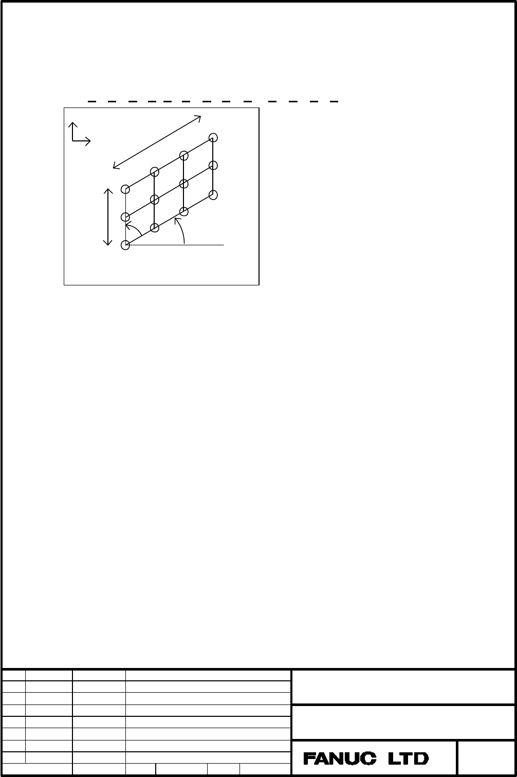
2.1.3 Grid (G202)
This is a menu for specifying the holes positions of a grid.
Create ISO code program in the following form.
G202 X Y U V I J K L Q (B C D E ) ;
X : Start point X
X coordinate of the position of the hole of the first point.
The first point is at the lower left position of the grid.
Y : Start point Y
Y coordinate of the position of the hole of the first point.
The first point is at the lower left position of the grid.
U : U – length
The length in the horizontal direction.
V : V – length
The length in the vertical direction
I : U – number
The number of the holes in the horizontal direction.
J : V – number
The number of the holes in the vertical direction
K : X – U angle
The angle between the line in the horizontal direction and the X axis.
It is considered to be 0 if not input.
K
U
V
(X, Y)
1
I
2
3
Grid
1
J
2
R
X
Y
Contents Summary of Embedded macro for milling Supplement to Manual
- Page 1FANUC Series 16i/18i/21i-MA Embedded macro for milling Specifications Contents 1. Outline 2 2. Details 3 2.1 Hole pattern 3 2.1.1 Points (G200) 3 2.1.2 Line (G201) 5 2.1.3 Grid (G202) 7 2.1.4 Square (G203) 9 2.1.5 Circle (G204) 11 2.1.6 Arc (G205) 12 2.2 Facing 14 2.2.1 Square surface (G210) 14 2.2.
- Page 21. Outline This specification describes how to program milling cycle machining using Embedded macro for milling. Embedded macro for milling is available for programming four canned cycles (Hole machining, Facing, Side cutting, Pocketing). Title FANUC Series 16i/18i/21i-MA Embedded macro for milling
- Page 32. Details The following descriptions show how to program each canned cycle. 2.1 Hole pattern The following menus are used for definition of hole’s position for the machining cycle of hole. Therefore these are used just behind the program of the machining cycle of hole. For creating a program of the
- Page 4X coordinate Y coordinate Point – 1 X Y Point – 2 A B Point – 3 C D Point – 4 E F Point – 5 H I Point – 6 J K Point – 7 R S Point – 8 T U Q : Pattern continue Selection whether to continue entering another hole pattern. 1: End 2: Continue #Example of a Hole pattern program (how to use address Q) O00
- Page 52.1.2 Line (G201) This is a menu for specifying the pattern of hole positions at same or different spaces on arbitrary line. Create ISO code program in the following form. G201 W X Y A N T Q (R B C • • • •); W : Space 1. Same space 2. Different space Y Y ` R X D X N C T 3 B 2 A A 1 (X, Y) (X, Y) Lin
- Page 6Omit point : To designate the point to be omitted, input the hole drilling sequence number including its points. Each address to the number is as follows. Omit point – 1 : B Omit point – 2 : C Omit point – 3 : D Omit point – 4 : E In the case of Different space : X : Start point X X coordinate of th
- Page 72.1.3 Grid (G202) This is a menu for specifying the holes positions of a grid. Create ISO code program in the following form. G202 X Y U V I J K L Q (B C D E ) ; Y X U J I V 2 3 R 2 K 1 1 (X, Y) Grid X : Start point X X coordinate of the position of the hole of the first point. The first point is at
- Page 8R : U – V angle The acute angle between the line defined by the points and the horizontal direction and vertical direction. It is considered to be a right angle if not input. Omit point : To designate the point to be omitted, input the hole drilling sequence number including its points. Each address
- Page 92.1.4 Square (G203) This is a menu for specifying the holes positions of a square. Create ISO code program in the following form. G203 X Y U V I J K R Q (B C D E ) ; Y X U J I V 2 3 R 2 K 1 1 (X, Y) Square X : Start point X X coordinate of the position of the hole of the first point. The first point
- Page 10R : U – V angle The acute angle between the line defined by the points and the horizontal direction and vertical direction. It is considered to be a right angle if not input. Omit point : To designate the point to be omitted, input the hole drilling sequence number including its points. Each address
- Page 112.1.5 Circle (G204) This is a menu for specifying the holes positions of a circle in a same space. Create ISO code program in the following form. G204 X Y R A N Q (B C • • • •) ; Y 2 1 X R A (X, Y) 3 N Hole Machining Sequence Circle 2 X : Center point X X coordinate of the center of the circle. 3 1
- Page 122.1.6 Arc (G205) This is a menu for specifying the holes positions of a same space arc or a different space arc. Create ISO code program in the following form. G205 W X Y R A N T Q (B C • • • •); W : Space 1. Same space arc 2. Different space arc Y Y X X 3 2 4 1 C B R T R D A N A E (X, Y) (X, Y) Arc
- Page 13Q : Pattern continue Selection whether to continue entering another hole pattern. 1: End 2: Continue Omit point : To designate the point to be omitted, input the hole drilling sequence number including its points. Each address to the number is as follows. Omit point – 1 : B Omit point – 2 : C Omit p
- Page 14Q : Pattern continue Selection whether to continue entering another hole pattern. 1: End 2: Continue. 2.2 Facing 2.2.1 Square surface (G210) This is a menu for facing the surface on a square shape plane. Create ISO code program in the following form. G210 P_ L_ Z_ B_ J H_ F_ C_ W_ X_ Y_ • • • •; K V
- Page 15J : Removal pitch The machining allowance of one pass for rough cutting in the Z direction. Rough cutting is done in one pass if not input. H : Finishing allowance The machining allowance in the Z direction for finish cutting. This is cut in one pass. Finish cutting is not done if not input. F : Fee
- Page 16A : Incline angle The angle between the U side and X axis, when the work is inclined with respect to the X axis. It is considered to be 0 if not input. A X axis Workpiece E : Start point The starting position of the machining (1, 2, 3, 4). If there is no input, 1 is regarded. [4] [2] [3] [1] M : App
- Page 17Movements : Rapid Traverse (G00) Feed Traverse (G01) Uni - direction Pitch Clearance Depth Z Finish ALW. X D Y C Cutting Width X A B Approach Gap Escape Gap a) In the case of rough cutting 1. Rapid traverse up to the starting point (A). 2. Rapid traverse along the Z axis up to the point equal to (EN
- Page 18b) In the case of finish cutting 1. Rapid traverse up to the starting point (A). 2. Rapid traverse along the Z axis up to the point equal to END POINT Z. 3. Cutting feed to the opposite side (B) of the starting point. 4. Rise along the Z axis in rapid traverse by an amount of CLEARANCE. 5. Rapid tra
- Page 19b) In the case of finish cutting 1. Rapid traverse up to the starting point (A). 2. Rapid traverse along the Z axis up to the point equal to END POINT Z. 3. Cutting feed to the other side (B) in the X axis (U direction). 4. Rapid traverse in the Y axis (V direction) to next starting point (C) accord
- Page 20b) In the case of finish cutting 1. Rapid traverse up to the starting point (A). 2. Rapid traverse along the Z axis up to the point equal to END POINT Z. 3. Cut spirally and finally move in cutting feed by an amount equal to ESCAPE GAP. 4. Rise along the Z axis in rapid traverse by an amount equal t
- Page 21H : Finishing allowance The machining allowance in the Z direction for finish cutting. This is cut in one pass. Finish cutting is not done if not input. F : Feed rate The feed rate of the tool. C : Cutting width The machining allowance one of pass in the XY direction. It is specified a rate (%) of t
- Page 22E : Start point The starting position of the machining (1, 2, 3, 4). If there is no input, 1 is regarded. [4] [2] [3] [1] M : Approach gap The gap between the tool edge in the cutting feed start point and the work. If there is no input, 5mm is regarded. N : Escape gap The gap between the tool edge a
- Page 232.3 Side cutting 2.3.1 Square side (G220) This is a menu for cutting the square shape side. Create ISO code program in the following form. G220 P Z S I D B J H F E • • • •; R I C V K J (X, Y) H B Z Z Y I D X S X U Square side Side cutting : Z-X plane T : Machining process 1: Roughing 2: Bottom finis
- Page 24The machining allowance of the bottom finish cutting. This is cut in one pass. Bottom finish cutting is not done if not input. I : Chamfer removal The amount of the chamfering. D : Tool small diameter The small diameter of chamfer tool. I Tool Diameter Workpiece D 1.1.1.1 J : Chamfer angle The tool
- Page 25X : Center point X X coordinate of the center of the square. Y : Center point Y Y coordinate of the center of the square. U : U-length The horizontal length of the square. V : V-length The vertical length of the square. In the case of Inside, be sure that U > V or U = V. If not, input Incline angle
- Page 26A : Incline angle The angle between the U side and X axis, when the work is inclined with respect to the X axis. It is considered to be 0 if not input. K : Approach gap The gap between the tool edge in the cutting feed start point and the work. If there is no input, 5mm is regarded. A X axis Workpie
- Page 27The following table shows addresses used in arguments in each machining process. G220 T Z S I D B J H I D J H M F E X Y U V Rough # # # # # # # # _ _ _ _ # # # # # # # Bottom finish # # # # # # _ # _ _ _ _ # # # # # # # Side finish # # _ _ _ # # # _ _ _ _ # # # # # # # Chamfer # # _ _ _ # _ _ # # #
- Page 28a) In the case of rough cutting 1. Rapid traverse up to the starting point (A). 2. Rapid traverse along the Z axis up to point R (END POINT Z + BOTTOM REMOVAL + CLEARANCE) 3. Descent along the lower Z axis in cutting feed (Z-CUT FEED RATE) by the pitch (BOTTOM PITCH). 4. Cutting movement (FEED RATE)
- Page 297. Move away the amount (CLEARANCE) along the Z axis. 8. Rapid traverse back to the starting point (B). 9. 2.-8. are repeated up to the point (END POINT Z). 10. Rapid traverse along Z axis up to point R (END POINT Z + BOTTOM REMOVAL + CLEARANCE). d) In the case of chamfering 1. Rapid traverse up to
- Page 302.3.2 Circle side (G221) This is a menu for cutting the circle shape side. Create ISO code program in the following form. G221 P Z S I D B J H F E • • • •; I C R J K (X, Y) H B Z Z Y I D X S X Side cutting : Z-X plane Circle side T : Machining process 1: Roughing 2: Bottom finishing 3: Side finishin
- Page 31H : Bottom finish The machining allowance of the bottom finish cutting. This is cut in one pass. Bottom finish cutting is not done if not input. I : Chamfer removal The amount of the chamfering. D : Tool small diameter The small diameter of chamfer tool. J : Chamfer angle The tool nose angle of a ch
- Page 32K : Approach gap The gap between the tool edge in the cutting feed start point and the work. If there is no input, 5mm is regarded. K : Approach / escape The radius of approach or escape. The movement is performed as a quarter arc. It is calculated automatically if not input. N : Start point The sta
- Page 332.3.3 Track side (G222) This is a menu for cutting the track shape side. Create ISO code program in the following form. G222 P Z S I D B J H F E • • • •; I C R J U K H B (X, Y) Z Z Y I D X X S Track side Side cutting : Z-X plane T : Machining process 1: Roughing 2: Bottom finishing 3: Side finishing
- Page 34H : Bottom finish The machining allowance of the bottom finish cutting. This is cut in one pass. Bottom finish cutting is not done if not input. I : Chamfer removal The amount of the chamfering. D : Tool small diameter The small diameter of chamfer tool. J : Chamfer angle The tool nose angle of a ch
- Page 35K : Approach gap The gap between the tool edge in the cutting feed start point and the work. If there is no input, 5mm is regarded. K : Approach / escape The radius of approach or escape. The movement is performed as a quarter arc. It is calculated automatically if not input. N : Start point The sta
- Page 362.3.4 One side (G223) This is a menu for cutting the one side only. Create ISO code program in the following form. G223 P Z S I D B J H F E • • • •; Y I C X J (X, Y) H B Z Z I D N U M X S One side Side cutting : Z-X plane T : Machining process 1: Roughing 2: Bottom finishing 3: Side finishing 4: Cha
- Page 37H : Bottom finish The machining allowance of the bottom finish cutting. This is cut in one pass. Bottom finish cutting is not done if not input. I : Chamfer removal The amount of the chamfering. D : Tool small diameter The small diameter of chamfer tool. J : Chamfer angle The tool nose angle of a ch
- Page 38A : Incline angle The angle between the U side and X axis, when the work is inclined with respect to the X axis. It is considered to be 0 if not input. M : Approach gap The gap between the tool edge in the machining start point and the workpiece edge. If there is no input, 5mm is regarded. N : Escap
- Page 39a) In the case of rough cutting 1. Rapid traverse up to the starting point (A). 2. Rapid traverse along the Z axis up to point R (END POINT Z + BOTTOM REMOVAL + CLEARANCE) 3. Rapid traverse toward one side by the pitch (SIDE PITCH). 4. Descent along the lower Z axis in cutting feed (Z-CUT FEED RATE)
- Page 407. 3.-6. are repeated up to the point (END POINT Z). 8. Rapid traverse along Z axis up to point R (END POINT Z + BOTTOM REMOVAL + CLEARANCE). d) In the case of chamfering 1. Rapid traverse up to the starting point (A). 2. Rapid traverse along the Z axis up to the cutting point. (Cutting point : It i
- Page 41T : Machining process 1: Roughing 2: Bottom finishing 3: Side finishing 4: Chamfering 5: Drilling Z : End point Z Z coordinate of the final machined surface B : Removal depth The depth of the pocket. J : Removal pitch The machining allowance of one pass for rough cutting in the Z direction. Rough cu
- Page 42H : Tool out depth The thrust depth of a chamfering tool. Tool Too l J H Workpiece F : The feed rate of the tool. E : Z_cut feed rate The cutting feed rate in Zaxis direction from point R. (Point R = End point Z + Bottom removal + Clearance) C : Cutting width The machining allowance of one pass in t
- Page 43W : Cutting direction 1: Down-cut : Rotation of the cutting tool in the forward direction 2: Up-cut : Rotation of the cutting tool in the reverse direction If there is no input, 1 is regarded. R : Corner R The amount of radius at a corner. R End-mill Corner R Down-cut Up-cut K : Approach / escape Th
- Page 44The following table shows addresses used in arguments in each machining process. G230 T Z B J H D C D J H C F E X Y U V Rough # # # # # # _ _ _ _ # # # # # # # Bottom finish # # # _ # # _ _ _ _ # # # # # # # Side finish # # # # # _ _ _ _ _ _ # # # # # # Chamfer # # # _ _ _ # # # # _ # # # # # # Dril
- Page 45a) In the case of rough cutting 1. Rapid traverse up to the starting point. 2. Rapid traverse along the Z axis up to point R (END POINT Z + REMOVAL DEPTH + CLEARANCE) 3. Descent along the lower Z axis in cutting feed (Z-CUT FEED RATE) by the pitch (REMOVAL PITCH). 4. Cutting from the inside to the o
- Page 467. Rapid traverse along Z axis up to point R (END POINT Z + REMOVAL DEPTH + CLEARANCE). d) In the case of chamfering 1. Rapid traverse up to the starting point. 2. Rapid traverse along the Z axis up to the cutting point. (Cutting point : It is calculated by END POINT Z, REMOVAL DEPTH, CHAMFER REMOVA
- Page 472.4.2 Circle pocket (G231) This is a menu for pocketing the circle shape. Create ISO code program in the following form. G231 P_ Z_ B_ J H_ F_ C_ W_ X_ Y_ • • • •; C M R J K (X, Y) HB Z Z Y D X X Circle pocket Pocketing : Z-X plane T : Machining process 1: Roughing 2: Bottom finishing 3: Side finish
- Page 48D : Tool small diameter The small diameter of chamfer tool. J : Chamfer angle The tool nose angle of a chamfering tool. H : Tool out depth The thrust depth of a chamfering tool. F : The feed rate of the tool. E : Z_cut feed rate The cutting feed rate in Zaxis direction from point R. (Point R = End p
- Page 49K : Approach / escape The radius of approach or escape. The movement is performed as a quarter arc. It is calculated automatically if not input. The following table shows addresses used in arguments in each machining process. G231 T Z B J H D C D J H C F E X Y R S Q M W K Rough # # # # # # _ _ _ _ #
- Page 50T : Machining process 1: Roughing 2: Bottom finishing 3: Side finishing 4: Chamfering 5: Drilling Z : End point Z Z coordinate of the final machined surface B : Removal depth The depth of the pocket. J : Removal pitch The machining allowance of one pass for rough cutting in the Z direction. Rough cu
- Page 51Y : Center point Y Y coordinate of the center of the left arc. U : Center distance The distance between the centers of the two arcs. R : Radius The radius of a circle. S : Cycle select Select the drilling cycle for pre-hole 1: G81 (Normal drilling) 2: G83 (Peck drilling) 3: G73 (High-speed peck dril
- Page 52The following table shows addresses used in arguments in each machining process. G232 T Z B J H D C D J H C F E X Y U R Rough # # # # # # _ _ _ _ # # # # # # # Bottom finish # # # _ # # _ _ _ _ # # # # # # # Side finish # # # # # _ _ _ _ _ _ # # # # # # Chamfer # # # _ _ _ # # # # _ # # # # # # Dril
- Page 532.4.4 Groove (G233) This is a menu for machining the linear groove. Create ISO code program in the following form. G233 P_ Z_ B_ J H_ F_ C_ W_ X_ Y_ • • • •; C M V J (X, Y) C HB Z Z Y D X X K U Q Groove Pocketing : Z-X plane T : Machining process 1: Roughing 2: Bottom finishing 3: Side finishing 4:
- Page 54J : Chamfer angle The tool nose angle of a chamfering tool. H : Tool out depth The thrust depth of a chamfering tool. F : The feed rate of the tool. C : Cutting width The machining allowance of one pass in the XY direction. It is specified a rate (%) of the tool. (less than 70%) X : Center point X X
- Page 55The following table shows addresses used in arguments in each machining process. G233 T Z B J H D C D J H F C X Y U V Rough # # # # # # _ _ _ _ # # # # # # Bottom finish # # # _ # # _ _ _ _ # # # # # # Side finish # # # # # _ _ _ _ _ # _ # # # # Chamfer # # # _ _ _ # # # # # _ # # # # G233 M W A K Q
- Page 56Movements : Rapid Traverse (G00) Feed Traverse (G01) Point R Removal Pitch Clearance Z Removal Depth Bottom Finish X Y Side Finish (X,Y) B A X Groove Width Approach / Escape Gap Cutting Width a) In the case of rough cutting 1. Rapid traverse up to the starting point (A). 2. Rapid traverse along the
- Page 575. Widening of the groove on the right and left sides symmetrically using the cutting width (CUTTING WIDTH). 6. The groove bottom side is cut leaving the side finish allowance (SIDE FINISH). 7. Rapid traverse along Z axis up to point R c) In the case of side finish cutting 1. Rapid traverse up to th
- Page 583. Notes (Note 1)This function requires the following optional functions. # Embedded Macro # Canned cycle # Custom macro B This function consists of 83 programs. So consider the number of programs which an operator requires and specify one of the following optional functions. # Number of Registered
- Page 594. Alarm Number Message Contents 3001 INPUT VALUE IS Necessary data is not entered. Or entered data ERRONEOUS. is invalid. 3002 OFFSET VALUE IS The offset data corresponding to the specified D UNDER 0. code is 0 or less. 3003 INTERFREE WITH The tool interferes with the opposite surface. WORK[RING] 3