Series 15i/150i - Model B Parameter manual Page 335
Parameter manual
B-63790EN/01 4.DESCRIPTION OF PARAMETERS
- 325 -
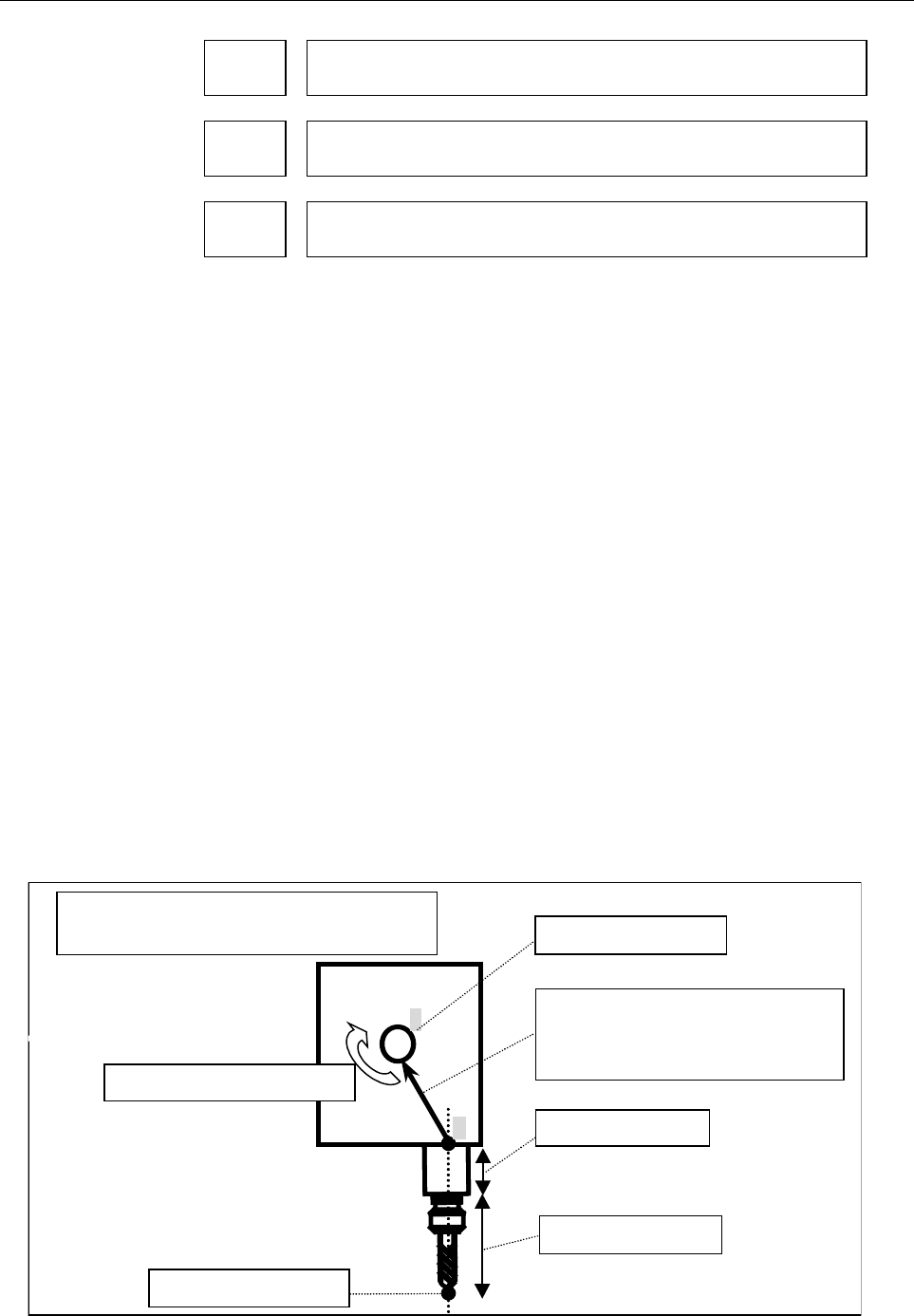
6190 Intersection offset vector between the tool axis and the first rotary axis of the
tool (X-axis, one of the basic three axes)
6191 Intersection offset vector between the tool axis and the first rotary axis of the
tool (Y-axis, one of the basic three axes)
6192 Intersection offset vector between the tool axis and the first rotary axis of the
tool (Z-axis, one of the basic three axes)
[Input type] Parameter input
[Data type] Real
[Valid data range] mm, inch (machine unit)
[Minimum unit of data] Depend on the increment system of the applied axis
[Valid data range] 9 digit of minimum unit of data (Refer to the standard parameter
setting table (A))
(When the increment system is IS-B, -999999.999 to +999999.999)
Set this parameter if the tool axis and the rotary axis of the tool do not
cross each other. The setting becomes effective if parameter No. 6161
= 1, 2, or 21.
If parameter No. 6161 = 1 or 21, when all the rotary axes for
controlling the tool are at 0 degrees, specify the vector from point D
on the tool axis to point E on the first rotary axis of the tool as the
intersection offset vector in the machine coordinate system.
If parameter No. 6161 = 2, when all the rotary axes for controlling the
tool are at 0 degrees, specify the vector from point D on the tool axis
to point E on the second rotary axis of the tool as the intersection
offset vector in the machine coordinate system.
(Caution)
Point D is a point from the tool center point obtained by taking the
tool length offset and tool holder offset (parameter No. 7548) into
account.
Select, as point E, a position where measurement is easy.
Intersection offset vector between
the tool axis and the first rotary
axis of the tool
First rotar
y
axis of the tool
If the tool axis and the tool rotary axis do
not cross each other
Tool center point
Tool holder offset
D
E
Tool length offset
Controlled point
Contents Summary of Series 15i/150i - Model B Parameter manual
- Page 1PARAMETER MANUAL B-63790EN/01
- Page 2• No part of this manual may be reproduced in any form. • All specifications and designs are subject to change without notice. The export of this product is subject to the authorization of the government of the country from where the product is exported. In this manual we have tried as much as possi
- Page 3B-63790EN/01 DEFINITION OF WARNING, CAUTION, AND NOTE DEFINITION OF WARNING, CAUTION, AND NOTE This manual includes safety precautions for protecting the user and preventing damage to the machine. Precautions are classified into Warning and Caution according to their bearing on safety. Also, supplem
- Page 4
- Page 5B-63790EN/01 PREFACE PREFACE Applicable product name The models covered by this manual, and their abbreviations are: Product name Abbreviations FANUC Series 15i-MB 15i-MB Series 15i FANUC Series 150i-MB 150i-MB Series 150i NOTE Some functions described in this manual may not be applied to some produ
- Page 6
- Page 7B-63790EN/01 TABLE OF CONTENTS TABLE OF CONTENTS DEFINITION OF WARNING, CAUTION, AND NOTE ................................ s-1 PREFACE.................................................................................................. p-1 1 DISPLAYING PARAMETERS AND PITCH ERROR COMPENSATION DATA......
- Page 8TABLE OF CONTENTS B-63790EN/01 4.10 ACCELERATION/DECELERATION CONTROL PARAMETERS (DATA NO. 1600 AND LATER) .................................................................107 4.11 SERVO PARAMETER (DATA NO. 1700 TO 1999 AND 2600 AND LATER).................................122 4.12 DI/DO PARAMETERS (D
- Page 9B-63790EN/01 TABLE OF CONTENTS APPENDIX A CHARACTER CODE LIST .................................................................423 B LIST OF COMPATIBLE PARAMETERS FOR SERIES 15-MB..........424 c-3
- Page 10
- Page 11B-63790EN/01 1.DISPLAYING PARAMETERS AND PITCH ERROR COMPENSATION DATA 1 DISPLAYING PARAMETERS AND PITCH ERROR COMPENSATION DATA This chapter explains how to display parameters and pitch error compensation data. -1-
- Page 121.DISPLAYING PARAMETERS AND PITCH ERROR COMPENSATION DATA B-63790EN/01 1.1 DISPLAYING PARAMETERS The Parameter screen displays the values specified for CNC parameters. Parameter screen Displaying the Parameter screen Follow either of the procedures described below to display the Parameter screen. Me
- Page 13B-63790EN/01 1.DISPLAYING PARAMETERS AND PITCH ERROR COMPENSATION DATA Displaying specified parameters The Parameter screen consists of multiple pages. Follow one of the procedures described below to display the specified parameter. Method 1 Using the
page keys, and the <↑> <↓> <←> - Page 141.DISPLAYING PARAMETERS AND PITCH ERROR COMPENSATION DATA B-63790EN/01 Selecting a group Move the cursor to the group to be displayed. Method 1 Use the <↑> <↓> <←> <→> cursor keys, move the cursor. Method 2 (1) Click the [NO. SEARCH] soft key. (2) Key in the number of the group to be displayed. (3)
- Page 15B-63790EN/01 1.DISPLAYING PARAMETERS AND PITCH ERROR COMPENSATION DATA 1.2 DISPLAYING PITCH ERROR COMPENSATION DATA The Pitch Error Compensation screen displays the values specified for pitch error compensation data. Pitch Error Compensation screen Displaying the Pitch Error Compensation screen Foll
- Page 161.DISPLAYING PARAMETERS AND PITCH ERROR COMPENSATION DATA B-63790EN/01 Displaying specified pitch error compensation data The Pitch Error Compensation screen consists of multiple pages. Follow one of the procedures described below to display specified pitch error compensation data. Method 1 Using th
- Page 17B-63790EN/01 2.SETTING PARAMETERS AND PITCH ERROR COMPENSATION DATA 2 SETTING PARAMETERS AND PITCH ERROR COMPENSATION DATA This chapter explains how to set parameters and pitch error compensation data from the MDI. -7-
- Page 182.SETTING PARAMETERS AND PITCH ERROR COMPENSATION DATA B-63790EN/01 2.1 SETTING PARAMETERS The Parameter screen is used to set parameters from the MDI. For an explanation of how to display the Parameter screen, see Section 1.1, "Displaying Parameters." Procedure for setting parameters - Entering the
- Page 19B-63790EN/01 2.SETTING PARAMETERS AND PITCH ERROR COMPENSATION DATA - Entering a setting (incremental input) Method 1 (1) Click the [+INPUT] soft key. (2) Key in the value to be added to the current setting. (3) Click the [EXEC] soft key. Method 2 (1) Key in the value to be added to the current sett
- Page 202.SETTING PARAMETERS AND PITCH ERROR COMPENSATION DATA B-63790EN/01 2.2 SETTING PITCH ERROR COMPENSATION DATA For an explanation of how to display the Pitch Error Compensation screen, see Section 1.2, "Displaying Pitch Error Compensation Data." The Pitch Error Compensation screen is used to set pitc
- Page 21B-63790EN/01 2.SETTING PARAMETERS AND PITCH ERROR COMPENSATION DATA - Entering a setting (incremental input) Method 1 (1) Click the [+INPUT] soft key. (2) Key in the value to be added to the current setting. (3) Click the [EXEC] soft key. Method 2 (1) Key in the value to be added to the current sett
- Page 223.INPUTTING AND OUTPUTTING PARAMETERS USING EXTERNAL INPUT/OUTPUT DEVICES B-63790EN/01 3 INPUTTING PARAMETERS AND USING OUTPUTTING EXTERNAL INPUT/OUTPUT DEVICES This chapter explains the procedures for inputting and outputting parameters using the input/output device connected to the reader/punch in
- Page 23B-63790EN/01 3.INPUTTING AND OUTPUTTING PARAMETERS USING EXTERNAL INPUT/OUTPUT DEVICES 3.1 INPUTTING AND OUTPUTTING PARAMETERS ON THE PARAMETER SCREEN This section explains the procedures for inputting and outputting parameters on the Parameter screen. Before parameters can be input and output, the
- Page 243.INPUTTING AND OUTPUTTING PARAMETERS USING EXTERNAL INPUT/OUTPUT DEVICES B-63790EN/01 Inputting parameters Method 1 (neither the input file name nor number need be specified) (1) Enter MDI mode. (2) Enter the emergency stop status. (3) Click the [READ] soft key. (4) Click the [PARAMETER] soft key.
- Page 25B-63790EN/01 3.INPUTTING AND OUTPUTTING PARAMETERS USING EXTERNAL INPUT/OUTPUT DEVICES NOTE 1 When outputting and inputting parameters to and from a FANUC Floppy Cassette, FANUC FA Card, and FANUC Handy File, you can specify the input/output file with its file name or number. 2 When outputting and i
- Page 263.INPUTTING AND OUTPUTTING PARAMETERS USING EXTERNAL INPUT/OUTPUT DEVICES B-63790EN/01 3.2 INPUTTING AND OUTPUTTING PARAMETERS ON THE FLOPPY DIRECTORY SCREEN This section explains the procedures for inputting and outputting parameters on the Floppy Directory screen, using the FANUC Floppy Cassette,
- Page 27B-63790EN/01 3.INPUTTING AND OUTPUTTING PARAMETERS USING EXTERNAL INPUT/OUTPUT DEVICES Inputting parameters (1) Click the [DATA SELECT] soft key. (2) Click the [PARAMETER] soft key. "PARAMETER" appears in IN/OUT DATA. (3) Click the [DIR. VIEW] soft key. A list of files contained in the input/output
- Page 283.INPUTTING AND OUTPUTTING PARAMETERS USING EXTERNAL INPUT/OUTPUT DEVICES B-63790EN/01 3.3 INPUTTING AND OUTPUTTING PARAMETERS ON THE MEMORY CARD SCREEN This section explains the procedures for inputting and outputting parameters on the Memory Card screen. Before parameters can be input and output,
- Page 29B-63790EN/01 3.INPUTTING AND OUTPUTTING PARAMETERS USING EXTERNAL INPUT/OUTPUT DEVICES Inputting parameters (1) Click the [DATA SELECT] soft key. (2) Click the [PARAMETER] soft key. "PARAMETER" appears in IN/OUT DATA. (3) Click the [DIR. VIEW] soft key. A list of files contained in the input/output
- Page 303.INPUTTING AND OUTPUTTING PARAMETERS USING EXTERNAL INPUT/OUTPUT DEVICES B-63790EN/01 3.4 INPUT/OUTPUT FORMATS This section explains the input/output formats for parameters and pitch error compensation data. 3.4.1 Input/Output Formats for Parameters Parameters are classified according to data types
- Page 31B-63790EN/01 3.INPUTTING AND OUTPUTTING PARAMETERS USING EXTERNAL INPUT/OUTPUT DEVICES - Inch/metric switching The data specified for parameters dependent on inch/metric switching, such as length and feedrate parameters, is determined to be in either inch or metric mode depending on the mode assumed
- Page 323.INPUTTING AND OUTPUTTING PARAMETERS USING EXTERNAL INPUT/OUTPUT DEVICES B-63790EN/01 - Bit spindle type format N ***** S * P ******** S * P ******** .. .. ; The numeric value following N represents the parameter number. The numeric value following S represents the spindle number (1 or above). The
- Page 33B-63790EN/01 3.INPUTTING AND OUTPUTTING PARAMETERS USING EXTERNAL INPUT/OUTPUT DEVICES - Integer axis type format N ***** A ** P ****** A ** P ****** .. .. ; The numeric value following N represents the parameter number. The numeric value following A represents the controlled axis number (1 or above
- Page 343.INPUTTING AND OUTPUTTING PARAMETERS USING EXTERNAL INPUT/OUTPUT DEVICES B-63790EN/01 - Real type format N ***** P ****** ; N ***** M ****** ; N ***** I ****** ; The numeric value following N represents the parameter number. The numeric value following P, M, or I represents the value (real) of the
- Page 35B-63790EN/01 3.INPUTTING AND OUTPUTTING PARAMETERS USING EXTERNAL INPUT/OUTPUT DEVICES - Real spindle type format N ***** S * P ****** S * P ****** .. .. ; N ***** S * M ****** S * M ****** .. .. ; N ***** S * I ****** S * I ****** .. .. ; The numeric value following N represents the parameter numbe
- Page 363.INPUTTING AND OUTPUTTING PARAMETERS USING EXTERNAL INPUT/OUTPUT DEVICES B-63790EN/01 3.4.2 Input/Output Format for Pitch Error Compensation Data - Keywords The following alphabetic characters are used as keywords. The numeric values following the keywords have the meanings described below. Keyword
- Page 37B-63790EN/01 4.DESCRIPTION OF PARAMETERS 4 DESCRIPTION OF PARAMETERS 4.1 DATA TYPES Parameters are classified according to data types, as follows: Data type Valid data range Remarks Bit type Bit axis type 0 or 1 Bit spindle type Integer type Some parameters are handled as Integer axis type 0 to ±999
- Page 384.DESCRIPTION OF PARAMETERS B-63790EN/01 4.2 REPRESENTATION OF PARAMETERS Bit, bit axis, and bit spindle types #7 #6 #5 #4 #3 #2 #1 #0 0000 EIA NCR ISP CTV TVC Data Data (#0 to #7 indicate bit positions.) number Types other than bit, bit axis, and bit spindle types 1023 Servo axis number of each axi
- Page 39B-63790EN/01 4.DESCRIPTION OF PARAMETERS 4.3 STANDARD PARAMETER SETTING TABLES Overview This section specifies the standard minimum data units and standard valid data ranges of real, real axis, and real spindle type CNC parameters. The data type of each parameter and its unit of data conform to the
- Page 404.DESCRIPTION OF PARAMETERS B-63790EN/01 (C) Velocity and angular velocity parameters Increment Unit of data Minimum data unit Valid data range system IS-A 0.01 0.0 to +2400000.0 IS-B 0.001 0.0 to +240000.0 mm/min IS-C 0.0001 0.0 to +99999.9999 deg./min IS-D 0.00001 0.0 to +9999.99999 IS-E 0.000001
- Page 41B-63790EN/01 4.DESCRIPTION OF PARAMETERS 4.4 SETTING PARAMETERS (DATA NO. 0000 AND LATER) #7 #6 #5 #4 #3 #2 #1 #0 0000 RDN EIA NCR ISP CTV TVC [Input type] Setting input [Data type] Bit #0 TVC Specifies whether TV check is performed. 0: Do not perform. 1: Perform. #1 CTV Specifies whether characters
- Page 424.DESCRIPTION OF PARAMETERS B-63790EN/01 #7 #6 #5 #4 #3 #2 #1 #0 0002 SJZ PZS CRF [Input type] Setting input [Data type] Bit #2 CRF Specifies how to punch an EOB (end-of-block) code when using ISO codes. 0: Use parameter NCR (No.0#3). 1: Punch CR LF. #3 PZS 0: Do not suppress the zeros of O numbers
- Page 43B-63790EN/01 4.DESCRIPTION OF PARAMETERS #7 #6 #5 #4 #3 #2 #1 #0 0010 SBO SBC SBM SB8 SB7 SQN INI [Input type] Setting input [Data type] Bit #0 INI Specifies whether the increment system is metric or in inches. 0: Metric input 1: Inch input #1 SQN Specifies whether sequence numbers are automatically
- Page 444.DESCRIPTION OF PARAMETERS B-63790EN/01 #7 #6 #5 #4 #3 #2 #1 #0 0011 NOT TIM ND8 NE8 [Input type] Setting input [Data type] Bit #0 NE8 Specifies whether to permit editing of O8000 to O8999 programs. 0: Permit editing. 1: Do not permit editing. #1 ND8 Specifies whether to display the program being e
- Page 45B-63790EN/01 4.DESCRIPTION OF PARAMETERS #7 #6 #5 #4 #3 #2 #1 #0 0013 DSL HDE HKE [Input type] Setting input [Data type] Bit #4 HKE Specifies whether to store the history of key operations. 0: Do not store the history. 1: Store the history. #5 HDE Specifies whether to store the history of DI/DO. 0:
- Page 464.DESCRIPTION OF PARAMETERS B-63790EN/01 #7 #6 #5 #4 #3 #2 #1 #0 0015 NDM EKE OHS HPC SPS SVS [Input type] Setting input [Data type] Bit #0 SVS Specifies whether to display the servo screen. 0: Display the servo screen. 1: Do not display the servo screen. Specifies whether to display or hide the ser
- Page 47B-63790EN/01 4.DESCRIPTION OF PARAMETERS The device numbers for each device are listed below: Device Device name number 1 RS-232-C channel 1 (JD5A on the main CPU board) 2 RS-232-C channel 2 (JD5B on the main CPU board) 3 RS-232-C channel 3 (JD36A on the display unit) 8 Memory card 9 PMC C board 10
- Page 484.DESCRIPTION OF PARAMETERS B-63790EN/01 0024 Assignment of the communication with the PMC Ladder development tool (FAPT LADDER-II, Ladder editing package) [Input type] Setting input [Data type] Integer [Valid data range] 0 - 255 Assigns the communication with the PMC Ladder development tool (FAPT L
- Page 49B-63790EN/01 4.DESCRIPTION OF PARAMETERS 0040 Serial port channel for Remote Diagnostic Function [Input type] Setting input [Data type] Integer [Valid data range] 1-3 Selection of serial port channel for Remote Diagnostic Function. 1: RS-232-C Serial port1 (JD5A) 2: RS-232-C Serial port2 (JD5B) 3: R
- Page 504.DESCRIPTION OF PARAMETERS B-63790EN/01 unauthorized persons from accessing system parameters and machining programs. Password 1: Sets a password for all services of the remote diagnosis function. (No remote diagnosis function services are available until this password is entered on the host comput
- Page 51B-63790EN/01 4.DESCRIPTION OF PARAMETERS 4.5 Timer Parameters (Data No. 0100 and later) 0100 Time accumulated since power-on [Input type] Parameter input [Data type] Integer [Unit of data] min [Valid data range] 0 - 999999999 Stores the time accumulated since power-on. 0101 Time 1 accumulated during
- Page 524.DESCRIPTION OF PARAMETERS B-63790EN/01 0104 Time 2 accumulated during cutting [Input type] Setting input [Data type] Integer [Unit of data] min [Valid data range] 0 - 999999999 Stores the time accumulated during cutting that is equal to or greater than one minute. The actual time accumulated durin
- Page 53B-63790EN/01 4.DESCRIPTION OF PARAMETERS 0109 Number of parts required [Input type] Setting input [Data type] Integer [Valid data range] 0 - 999999999 Sets the number of parts required. When the total number of machined parts exceeds the value of this parameter, a signal indicating that the number o
- Page 544.DESCRIPTION OF PARAMETERS B-63790EN/01 4.6 AXIS CONTROL PARAMETERS (DATA NO. 1000 AND LATER) #7 #6 #5 #4 #3 #2 #1 #0 1000 EMI EHM FPI XIK CSZ CIP [Input type] Parameter input [Data type] Bit #0 CIP Specifies what to confirm with an in-position check. 0: Merely confirm that the specified feedrate r
- Page 55B-63790EN/01 4.DESCRIPTION OF PARAMETERS #7 #6 #5 #4 #3 #2 #1 #0 1001 CAF PED PDC RPC [Input type] Setting input [Data type] Bit #0 RPC Specifies whether axes are switched when a reference position return (G29) is performed. 0: Axes are not switched. 1: Axes are switched. #5 PDC Specifies whether th
- Page 564.DESCRIPTION OF PARAMETERS B-63790EN/01 #7 #6 #5 #4 #3 #2 #1 #0 1004 DSP [Input type] Parameter input [Data type] Bit axis #6 DSP Specifies whether to display axis positions in the position screen and the program check screen. 0: Display axis positions. 1: Do not display axis positions. NOTE When u
- Page 57B-63790EN/01 4.DESCRIPTION OF PARAMETERS #6 MLE Specifies whether machine lock is valid for each axis. 0: Invalid. 1: Valid. #7 RMB For each axis, specifies whether the control axis detach signal and setting input RMV (bit 7 of parameter No. 0012) is valid. 0: Invalid. 1: Valid. #7 #6 #5 #4 #3 #2 #1
- Page 584.DESCRIPTION OF PARAMETERS B-63790EN/01 #5 ZMI Specifies the direction of manual reference position return. 0: Positive direction 1: Negative direction #6 NDC Specifies the normal direction control function. 0: Not normal direction control axis 1: Normal direction control axis Only one axis can be
- Page 59B-63790EN/01 4.DESCRIPTION OF PARAMETERS #7 #6 #5 #4 #3 #2 #1 #0 1008 DCL SFD ROT [Input type] Parameter input [Data type] Bit axis NOTE After this parameter has been set, the power must be off turned off then back on for the setting to become effective. #1 ROT 0: Not multiple rotary control axes. 1
- Page 604.DESCRIPTION OF PARAMETERS B-63790EN/01 #5 MCC If the controlled axis is detached, the MCC signal of the servo amplifier is: 0: Turned OFF. 1: Not turned OFF. If the controlled axis is detached when this parameter bit is 1, the servo motor is deactivated, but the MCC signal of the servo amplifier i
- Page 61B-63790EN/01 4.DESCRIPTION OF PARAMETERS #7 #6 #5 #4 #3 #2 #1 #0 1010 SYC [Input type] Parameter input [Data type] Bit axis #0 SYC Specifies whether to use the synchronization alignment function based on machine coordinates in the synchronous control function. 0: Not used 1: Used This parameter can
- Page 624.DESCRIPTION OF PARAMETERS B-63790EN/01 #7 #6 #5 #4 #3 #2 #1 #0 1013 WAM MCS HJZ NCG IM0 [Input type] Parameter input [Data type] Bit axis #0 IM0 Specifies whether to set the least input increment of each axis to ten times the least command increment when a command is issued without the decimal poi
- Page 63B-63790EN/01 4.DESCRIPTION OF PARAMETERS #7 WAM WAM In the NC window function, the reading of the current machine position (machine coordinates with the servo delay and the acceleration/deceleration delay considered) is: 0: Not performed. 1: Performed. NOTE Set the bit to "0" to keep the load on the
- Page 644.DESCRIPTION OF PARAMETERS B-63790EN/01 (Example 2) The controlled axes include only the linear axes X, Y, and Z. By using the tool attachment, the tool axis is tilted in the same tool axis direction as when the A- and C-axes are rotated. RAM (No.1014#0) RAP(No.1014#1) Angle (No.7516) X 1 1 45.0 Y
- Page 65B-63790EN/01 4.DESCRIPTION OF PARAMETERS 1020 Program axis name for each axis [Input type] Parameter input [Data type] Integer axis [Valid data range] 65 - 90 The programmed axis name of each controlled axis is set according to the following table: Axis name X Y Z A B C U V W Setting 88 89 90 65 66
- Page 664.DESCRIPTION OF PARAMETERS B-63790EN/01 1022 Designation of each axis in relation to the basic coordinate system [Input type] Parameter input [Data type] Integer axis [Valid data range] 0-7 To determine the planes selected for circular interpolation, cutter compensation, and so forth G17: Xp-Yp pla
- Page 67B-63790EN/01 4.DESCRIPTION OF PARAMETERS 1023 Servo axis number of each axis NOTE After this parameter has been set, the power must be off turned off then back on for the setting to become effective. [Input type] Parameter input [Data type] Integer axis [Valid data range] 0 - Max axes Specify the nu
- Page 684.DESCRIPTION OF PARAMETERS B-63790EN/01 1027 Spindle number of a spindle positioning axis NOTE After this parameter has been set, the power must be off turned off then back on for the setting to become effective. [Input type] Parameter input [Data type] Integer axis [Valid data range] 0-4 Set the a
- Page 69B-63790EN/01 4.DESCRIPTION OF PARAMETERS 1028 Spindle number of a Cs contour control axis NOTE After this parameter has been set, the power must be off turned off then back on for the setting to become effective. [Input type] Parameter input [Data type] Integer axis [Valid data range] 0-4 1029 Axis
- Page 704.DESCRIPTION OF PARAMETERS B-63790EN/01 1031 Reference axis [Input type] Parameter input [Data type] Integer [Valid data range] 0 - Max axes The units of parameters common to all axes, such as the dry run feedrate and feedrate specified by code F with one digit, vary according to the increment syst
- Page 71B-63790EN/01 4.DESCRIPTION OF PARAMETERS 1043 Series name of the servo program used NOTE After specifying this parameter, turn the power off, and then on again, for the new setting to take effect. [Input type] Parameter input [Data type] Integer axis [Invalid data range] 0 to 8 If using two or more
- Page 724.DESCRIPTION OF PARAMETERS B-63790EN/01 1049 Axis switching number [Input type] Setting input [Data type] Integer [Valid data range] 0-5 Six axis switching combinations are available. To choose from the six, set a desired axis switching number. The machine axes x, y, and z correspond to program add
- Page 73B-63790EN/01 4.DESCRIPTION OF PARAMETERS 1080 Address conversion table value (ATR) for slave 1 1081 Address conversion table value (ATR) for slave 2 1082 Address conversion table value (ATR) for slave 3 1083 Address conversion table value (ATR) for slave 4 1084 Address conversion table value (ATR) f
- Page 744.DESCRIPTION OF PARAMETERS B-63790EN/01 NOTE 1 When using the electronic gear box (EGB) function Although EGB and dummy axes do not require amplifiers, assume that they are connected to dummy amplifiers. Thus, as the address conversion table value for an non-existing slave, set the value equal to t
- Page 75B-63790EN/01 4.DESCRIPTION OF PARAMETERS #7 #6 #5 #4 #3 #2 #1 #0 1092 DSP [Input type] Parameter input [Data type] Bit axis NOTE After this parameter has been set, the power must be off turned off then back on for the setting to become effective. #0 DSP Usually, do not directly enter any value, beca
- Page 764.DESCRIPTION OF PARAMETERS B-63790EN/01 #6 PM1 Specifies whether to use the first pulse module. 0: Do not use. 1: Use. #7 PM2 Specifies whether to use the second pulse module. 0: Do not use. 1: Use. 1094 Connector number of the 1-st pulse module 1095 Connector number of the 2-nd pulse module NOTE A
- Page 77B-63790EN/01 4.DESCRIPTION OF PARAMETERS 1097 Master and slave numbers for tandem control (on the FSSB setting screen only) NOTE After this parameter has been set, the power must be off turned off then back on for the setting to become effective. [Input type] Parameter input [Data type] Integer axis
- Page 784.DESCRIPTION OF PARAMETERS B-63790EN/01 If the FSSB setup mode is automatic setting (bit 0 of parameter No. 1090 is 0), these parameters are automatically specified. Be sure to specify the parameters if the mode is manual setting (bit 0 of parameter no. 1090 is 1). Set the address translation table
- Page 79B-63790EN/01 4.DESCRIPTION OF PARAMETERS 4.7 CHOPPING PARAMETERS (DATA NO. 1181 AND LATER) #7 #6 #5 #4 #3 #2 #1 #0 1181 CRO [Input type] Parameter input [Data type] Bit #5 CRO Specifies the type of override used within the range from the chopping start position to point R, as follows: 0: Chopping ov
- Page 804.DESCRIPTION OF PARAMETERS B-63790EN/01 1194 Lower limit for chopping [Input type] Parameter input [Data type] Real [Unit of data] mm, inch, degree (input unit) [Minimum unit of data] Depend on the increment system of the reference axis [Valid data range] 9 digit of minimum unit of data (refer to s
- Page 81B-63790EN/01 4.DESCRIPTION OF PARAMETERS 1198 Chopping rate for enabling bottom dead point overshoot damp control when the chopping rate is changed [Input type] Parameter input [Data type] Real [Unit of data] mm/min, inch/min, degree/min (machine unit) [Minimum unit of data] Depend on the increment
- Page 824.DESCRIPTION OF PARAMETERS B-63790EN/01 4.8 COORDINATE SYSTEM PARAMETERS (DATA NO. 1200 AND LATER) #7 #6 #5 #4 #3 #2 #1 #0 1200 ACP NZA DSC MNS FPC [Input type] Parameter input [Data type] Bit #1 FPC Specifies whether to preset the relative position display to zero when the floating reference posit
- Page 83B-63790EN/01 4.DESCRIPTION OF PARAMETERS 1220 Common offset from the workpiece reference point for all axes [Input type] Setting input [Data type] Real axis [Unit of data] mm, inch, degree (input unit) [Minimum unit of data] Depend on the increment system of the applied axis [Valid data range] 9 dig
- Page 844.DESCRIPTION OF PARAMETERS B-63790EN/01 1240 Coordinates of the first reference position in the machine coordinate system NOTE After this parameter has been set, the power must be off turned off then back on for the setting to become effective. [Input type] Parameter input [Data type] Real axis [Un
- Page 85B-63790EN/01 4.DESCRIPTION OF PARAMETERS 1243 Coordinates of the fourth reference position in the machine coordinate system [Input type] Parameter input [Data type] Real axis [Unit of data] mm, inch, degree (machine unit) [Minimum unit of data] Depend on the increment system of the applied axis [Val
- Page 864.DESCRIPTION OF PARAMETERS B-63790EN/01 1265 Rounding value for absolute and relative coordinates on a rotation axis which keeps turned in the same direction [Input type] Parameter input [Data type] Real axis [Unit of data] Degree [Minimum unit of data] Depend on the increment system of the applied
- Page 87B-63790EN/01 4.DESCRIPTION OF PARAMETERS - When this parameter is set to 100000.000 When the absolute coordinate is 0°, the machine coordinate may not be 0° as shown below: Absolute and relative 0° 100000° 0° 100000° 0° coordinate system (-100000°) (-100000°) Machine coordinate system 0° 280° 200° 1
- Page 884.DESCRIPTION OF PARAMETERS B-63790EN/01 Absolute coordinate 0 360000 0 360000 0 system (-360000) (-360000) 180000 -180000 180000 -180000 -220000 N1 140000 N2 -30000 N3 N4 - Manual movement When this function is used and the manual absolute switch is turned on for manual intervention during automati
- Page 89B-63790EN/01 4.DESCRIPTION OF PARAMETERS 1280 Coordinates of diagonal vertex 1 of area 1 in automatic feedrate control by area 1281 Coordinates of diagonal vertex 2 of area 1 in automatic feedrate control by area 1282 Coordinates of diagonal vertex 1 of area 2 in automatic feedrate control by area 1
- Page 904.DESCRIPTION OF PARAMETERS B-63790EN/01 4.9 FEEDRATE PARAMETERS (DATA NO. 1400 AND LATER) #7 #6 #5 #4 #3 #2 #1 #0 1400 AOV LRP SFP RPD TDR RDR [Input type] Parameter input [Data type] Bit #0 RDR Specifies whether dry runs can be performed for the rapid traverse command. 0: Cannot be performed. 1: C
- Page 91B-63790EN/01 4.DESCRIPTION OF PARAMETERS #7 #6 #5 #4 #3 #2 #1 #0 1401 RFO HTG NED [Input type] Parameter input [Data type] Bit #1 NED Specifies effective range of external deceleration. 0: Affects all feed movement. 1: Affects only rapid traverse. #2 HTG Specifies the type of feedrate that is used f
- Page 924.DESCRIPTION OF PARAMETERS B-63790EN/01 #7 #6 #5 #4 #3 #2 #1 #0 1403 OVRB APO [Input type] Parameter input [Data type] Bit #0 APO The least increment for the second feedrate override is 0: 1% 1: 0.01% This parameter is effective only when AOV (bit 5 of parameter No. 1400) is 1. #6 OVRB In look-ahea
- Page 93B-63790EN/01 4.DESCRIPTION OF PARAMETERS (sec/block specification) (02h) , Feed per revolution (12h) , Skip (13h) , and External pulse synchronization (1Bh) commands. It also affects the feedrate specified in the Cutting feed (feed per minute ) (01h) , Feed per revolution (12h) , and Skip (13h) comm
- Page 944.DESCRIPTION OF PARAMETERS B-63790EN/01 #7 #6 #5 #4 #3 #2 #1 #0 1406 PVR F1O [Input type] Parameter input [Data type] Bit #0 F1O Specifies whether to enable feedrate override, second feedrate override, and override cancellation for the feedrates of F codes with a one-digit number (F1 to F9) . 0: Di
- Page 95B-63790EN/01 4.DESCRIPTION OF PARAMETERS #2 RPD Sets the feedrate of PMC-controlled axis in rapid traverse, machine coordinate system selection, and 1st to 4th reference position return in axis control by PMC. 0: Feedrate set in parameter No. 1420 1: Feedrate specified as the feedrate data in the ax
- Page 964.DESCRIPTION OF PARAMETERS B-63790EN/01 1411 Arbitrary manual angle feedrate [Input type] Parameter input [Data type] Real [Unit of data] mm/min, inch/min (machine unit) [Minimum unit of data] Depend on the increment system of the reference axis [Valid data range] Refer to the standard parameter se
- Page 97B-63790EN/01 4.DESCRIPTION OF PARAMETERS 1417 Rapid traverse ratio during the period from the power on to manual reference position return [Input type] Parameter input [Data type] Integer [Unit of data] % [Valid data range] 0 - 100 Set the rapid traverse ratio to use in the below expression. This ex
- Page 984.DESCRIPTION OF PARAMETERS B-63790EN/01 1421 F0 feedrate for each axis for rapid traverse override [Input type] Parameter input [Data type] Real axis [Unit of data] mm/min, inch/min, degree/min (machine unit) [Minimum unit of data] Depend on the increment system of the applied axis [Valid data rang
- Page 99B-63790EN/01 4.DESCRIPTION OF PARAMETERS 1426 External deceleration rate during cutting feed [Input type] Parameter input [Data type] Real [Unit of data] mm/min, inch/min, degree/min (machine unit) [Minimum unit of data] Depend on the increment system of the reference axis [Valid data range] Refer t
- Page 1004.DESCRIPTION OF PARAMETERS B-63790EN/01 1450 Resolution of the feedrate specified by the F code with a one-digit number [Input type] Parameter input [Data type] Integer [Valid data range] 1 - 127 Set the constant used to determine the change in the feedrate when the manual pulse generator is rotate
- Page 101B-63790EN/01 4.DESCRIPTION OF PARAMETERS 1460 Upper feedrate limit for F1 to F4 [Input type] Parameter input [Data type] Real [Unit of data] mm/min, inch/min, degree/min (machine unit) [Minimum unit of data] Depend on the increment system of the reference axis [Valid data range] Refer to the standar
- Page 1024.DESCRIPTION OF PARAMETERS B-63790EN/01 1473 Acceleration/deceleration reference speed for the bell-shaped acceleration/deceleration time constant change function [Input section] Setting input [Data type] Real type [Unit of data] mm/min, inch/min, degrees/min (input unit) [Minimum data unit] Follow
- Page 103B-63790EN/01 4.DESCRIPTION OF PARAMETERS 1483 Lower feedrate limit for the deceleration function based on the acceleration of fine HPCC [Input type] Parameter input [Data type] Real [Unit of data] mm/min, inch/min, degree/min (machine unit) [Minimum unit of data] Depend on the increment system of th
- Page 1044.DESCRIPTION OF PARAMETERS B-63790EN/01 1491 Lower feedrate limit for the deceleration function based on the acceleration during circular interpolation (for normal mode) [Input type] Parameter input [Data type] Real [Unit of data] mm/min, inch/min, degree/min (machine unit) [Minimum unit of data] D
- Page 105B-63790EN/01 4.DESCRIPTION OF PARAMETERS 1494 Feedrate during reverse movement [Input type] Parameter input [Data type] Real [Unit of data] mm/min, inch/min, degree/min (machine unit) [Minimum unit of data] Depend on the increment system of the reference axis [Valid data range] Refer to the standard
- Page 1064.DESCRIPTION OF PARAMETERS B-63790EN/01 #3 ROU Specifies whether automatic tuning function (ROUGH) is enabled on the HPCC (SETTING) screen. 0: Enabled. 1: Disabled. #4 LAA Bit related to the enabling and disabling of acceleration/deceleration before look-ahead interpolation 0: Whether acceleration/
- Page 107B-63790EN/01 4.DESCRIPTION OF PARAMETERS #6 FNW Specifies whether the method of determining the feedrate based on the feedrate difference in acceleration/deceleration before look-ahead interpolation and the method of determining the feedrate based on the acceleration of fine HPCC are the same as tho
- Page 1084.DESCRIPTION OF PARAMETERS B-63790EN/01 1520 Finishing level (for finishing) [Input type] Parameter input [Data type] Integer [Valid data range] 0 - 100 Stores the finishing level for the finishing parameter set. Usually, the finishing level is entered from the HPCC (SETTING) screen and, therefore,
- Page 109B-63790EN/01 4.DESCRIPTION OF PARAMETERS 1533 Acceleration level (for finishing) [Input type] Parameter input [Data type] Integer [Unit of data] % [Valid data range] 0 - 200 Stores the acceleration level for the finishing parameter set. Usually, the level is entered from the HPCC (SETTING) screen an
- Page 1104.DESCRIPTION OF PARAMETERS B-63790EN/01 1536 Time required to reach the maximum acceleration of pre-interpolation bell- shaped acceleration/deceleration (for finishing) [Input type] Parameter input [Data type] Integer [Unit of data] msec [Valid data range] 0 - 200 Stores the pre-interpolation bell-
- Page 111B-63790EN/01 4.DESCRIPTION OF PARAMETERS 1542 Post-interpolation acceleration/deceleration time constant (for medium finishing) [Input type] Parameter input [Data type] Integer axis [Unit of data] msec [Valid data range] 0 - 4000 Stores the post-interpolation acceleration/deceleration time constant
- Page 1124.DESCRIPTION OF PARAMETERS B-63790EN/01 1554 Tangent direction acceleration (for medium finishing) [Input type] Parameter input [Data type] Real axis [Unit of data] mm/sec/sec, inch/sec/sec, degree/sec/sec (machine unit) [Minimum unit of data] Depend on the increment system of the applied axis [Val
- Page 113B-63790EN/01 4.DESCRIPTION OF PARAMETERS 1559 Acceleration/deceleration speed (for semifinishing) for the bell-shaped acceleration/deceleration time constant change function [Input type] Setting input [Data type] Real type [Unit of data] mm/min, inch/min, degrees/min (input unit) [Minimum data unit]
- Page 1144.DESCRIPTION OF PARAMETERS B-63790EN/01 1564 Corner feedrate difference (for rough finishing) [Input type] Parameter input [Data type] Real axis [Unit of data] mm/min, inch/min, degree/min (machine unit) [Minimum unit of data] Depend on the increment system of the applied axis [Valid data range] Re
- Page 115B-63790EN/01 4.DESCRIPTION OF PARAMETERS 1574 Tangent direction acceleration (for rough finishing) [Input type] Parameter input [Data type] Real axis [Unit of data] mm/sec/sec, inch/sec/sec, degree/sec/sec (machine unit) [Minimum unit of data] Depend on the increment system of the applied axis [Vali
- Page 1164.DESCRIPTION OF PARAMETERS B-63790EN/01 1579 Acceleration/deceleration reference speed (for roughing) for the bell-shaped acceleration/deceleration time constant change function [Input type] Setting input [Data type] Real type [Unit of data] mm/min, inch/min, degrees/min (input unit) This parameter
- Page 117B-63790EN/01 4.DESCRIPTION OF PARAMETERS 4.10 ACCELERATION/DECELERATION CONTROL PARAMETERS (DATA NO. 1600 AND LATER) #7 #6 #5 #4 #3 #2 #1 #0 1600 NEX JGE CTE REX [Input type] Parameter input [Data type] Bit axis #0 REX Specifies acceleration/deceleration for rapid traverse as follows: 0: constant-ac
- Page 1184.DESCRIPTION OF PARAMETERS B-63790EN/01 #7 #6 #5 #4 #3 #2 #1 #0 1603 BCG FRP [Input type] Parameter input [Data type] Bit #5 FRP To linear type rapid traverse: 0: Acceleration/deceleration after interpolation is applied. The type of acceleration/deceleration after interpolation is determined by bit
- Page 119B-63790EN/01 4.DESCRIPTION OF PARAMETERS 1620 Time constant (T) for linear acceleration/deceleration or time constant (T1) for bell-shaped acceleration/deceleration for rapid traverse along each axis [Input type] Parameter input [Data type] Integer axis [Unit of data] msec [Valid data range] 0 - 400
- Page 1204.DESCRIPTION OF PARAMETERS B-63790EN/01 1621 FL feedrate for linear or bell-shaped acceleration/deceleration for rapid traverse along each axis [Input type] Parameter input [Data type] Real axis [Unit of data] mm/min, inch/min, degree/min (machine unit) [Minimum unit of data] Depend on the incremen
- Page 121B-63790EN/01 4.DESCRIPTION OF PARAMETERS 1622 Cutting feed acceleration/deceleration time constant for each axis [Input type] Parameter input [Data type] Integer axis [Unit of data] msec [Valid data range] 0 - 4000 For each axis, set the time constant used for acceleration/deceleration during cuttin
- Page 1224.DESCRIPTION OF PARAMETERS B-63790EN/01 1623 FL feedrate for cutting feed acceleration/deceleration after interpolation along each axis [Input type] Parameter input [Data type] Real axis [Unit of data] mm/min, inch/min, degree/min (machine unit) [Minimum unit of data] Depend on the increment system
- Page 123B-63790EN/01 4.DESCRIPTION OF PARAMETERS 1627 FL feedrate for each axis for acceleration/deceleration during the threading cycle [Input type] Parameter input [Data type] Real axis [Unit of data] mm/min, inch/min, degree/min (machine unit) [Minimum unit of data] Depend on the increment system of the
- Page 1244.DESCRIPTION OF PARAMETERS B-63790EN/01 1635 Time constant for cutting feed acceleration/deceleration after interpolation in the mode of look-ahead acceleration/deceleration before interpolation [Input type] Parameter input [Data type] Integer axis [Unit of data] msec [Valid data range] 0 - 4000 In
- Page 125B-63790EN/01 4.DESCRIPTION OF PARAMETERS 1645 Parameter 2 to set acceleration/deceleration for each axis when a constant feedrate command for PMC axis control is specified [Input type] Parameter input [Data type] Integer axis [Unit of data] msec [Valid data range] 0 - 32767 Specify the time it takes
- Page 1264.DESCRIPTION OF PARAMETERS B-63790EN/01 1660 Maximum allowable acceleration of acceleration/deceleration before interpolation for each axis [Input type] Parameter input [Data type] Real axis [Unit of data] mm/sec/sec, inch/sec/sec, degree/sec/sec (machine unit) [Minimum unit of data] Depend on the
- Page 127B-63790EN/01 4.DESCRIPTION OF PARAMETERS 1665 Allowable acceleration in the deceleration function based on the acceleration during circular interpolation for each axis (for normal mode) [Input type] Parameter input [Data type] Real axis [Unit of data] mm/sec/sec, inch/sec/sec, degree/sec/sec (machin
- Page 1284.DESCRIPTION OF PARAMETERS B-63790EN/01 1671 Per-axis maximum permissible acceleration of before-interpolation acceleration/deceleration for linear type rapid traverse or reference permissible acceleration of optimum torque acceleration/deceleration [Input type] Parameter input [Data type] Real axi
- Page 129B-63790EN/01 4.DESCRIPTION OF PARAMETERS 1672 Acceleration change time of before-interpolation bell-shaped acceleration/deceleration for linear type rapid traverse or acceleration change time of bell-shaped acceleration/deceleration in optimum torque acceleration/deceleration [Input type] Parameter
- Page 1304.DESCRIPTION OF PARAMETERS B-63790EN/01 1673 Permissible acceleration change level for each axis in speed control based on acceleration changes for jerk control [Input type] Parameter input [Data type] Real axis [Unit of data] mm/sec/sec, inch/sec/sec, degree/sec/sec (machine unit) [Minimum unit of
- Page 131B-63790EN/01 4.DESCRIPTION OF PARAMETERS 1675 Ratio of the jerk control change time in smooth bell-shaped acceleration/deceleration before interpolation [Input type] Parameter input [Data type] Integer [Unit of data] % [Valid data range] 0 to 50 Specify the percent jerk control change time with resp
- Page 1324.DESCRIPTION OF PARAMETERS B-63790EN/01 4.11 SERVO PARAMETER (DATA NO. 1700 TO 1999 AND 2600 AND LATER) The following parameters are not explained in this manual. Refer to FANUC AC SERVO MOTOR αi series PARAMETER MANUAL (B-65270EN) . No. Data type Contents 1702 Word axis Fine acceleration/decelerat
- Page 133B-63790EN/01 4.DESCRIPTION OF PARAMETERS No. Data type Contents 1855 Word axis Velocity loop integral gain (PK1V) 1856 Word axis Velocity loop proportional gain (PK2V) 1857 Word axis Velocity loop incomplete integral gain (PK3V) 1858 Word axis Velocity loop gain (PK4V) 1859 Word axis Observe paramet
- Page 1344.DESCRIPTION OF PARAMETERS B-63790EN/01 No. Data type Contents 1974 Word axis Dual position feedback zero-point amplitude 1975 Word axis Backlash acceleration stop amount 1976 Word axis Brake control timer (ms) 1977 Word axis Numerator of the flexible feed gear 1978 Word axis Denominator of the fle
- Page 135B-63790EN/01 4.DESCRIPTION OF PARAMETERS #7 #6 #5 #4 #3 #2 #1 #0 1707 HR3 [Input type] Parameter input [Data type] Bit axis #0 HR3 HIGH SPEED HRV mode is 0: Disabled. 1: Enabled. Refer to the "FANUC AC SERVO MOTOR αi series PARAMETER MANUAL (B-65270EN)" for details. 1716 Torque command difference th
- Page 1364.DESCRIPTION OF PARAMETERS B-63790EN/01 #7 #6 #5 #4 #3 #2 #1 #0 1800 IVO SAK CIN CCI RFW FVF CVR [Input type] Parameter input [Data type] Bit #1 CVR Specifies whether to issue a servo alarm if velocity control ready signal VRDY turns on before position control ready signal PRDY turns on. 0: Does no
- Page 137B-63790EN/01 4.DESCRIPTION OF PARAMETERS #5 CIN When CCI is 1, the CIN bit specifies the condition under which the cutting feed parameter defines the cutting-feed effective area. 0: Used only when the next block specifies cutting feed. 1: Always used regardless of the next block. The relationship of
- Page 1384.DESCRIPTION OF PARAMETERS B-63790EN/01 #7 #6 #5 #4 #3 #2 #0 1801 FFN [Input type] Parameter input [Data type] Bit NOTE After this parameter has been set, the power must be off turned off then back on for the setting to become effective. #1 FFN Specifies whether to enable the feed-forward function
- Page 139B-63790EN/01 4.DESCRIPTION OF PARAMETERS #7 #6 #5 #4 #3 #2 #1 #0 1803 MVB CLP ADJ [Input type] Parameter input [Data type] Bit axis #1 ADJ Specifies the axis along which to move in adjustment mode in synchronous control. 0: Not an axis along which to move in adjustment mode. 1: Axis along which to m
- Page 1404.DESCRIPTION OF PARAMETERS B-63790EN/01 #7 #6 #5 #4 #3 #2 #1 #0 1804 CNT RBK DGP PLC [Input type] Parameter input [Data type] Bit axis NOTE After this parameter has been set, the power must be off turned off then back on for the setting to become effective. #0 PLC PLC01 Specifies whether the value
- Page 141B-63790EN/01 4.DESCRIPTION OF PARAMETERS NOTE For the FS15B, this parameter bit was specified as follows. (This was not described in the manual.) During servo-off, an in-position check is 0: Performed. 1: Not performed. #6 NAD Specifies whether to perform A/D conversion of spindle or servo motor cur
- Page 1424.DESCRIPTION OF PARAMETERS B-63790EN/01 #7 #6 #5 #4 #3 #2 #1 #0 1816 ACM [Input type] Parameter input [Data type] Bit axis NOTE After this parameter has been set, the power must be off turned off then back on for the setting to become effective. #7 ACM Specify whether to use an optional command mul
- Page 143B-63790EN/01 4.DESCRIPTION OF PARAMETERS 1820 Command multiplier for each axis (CMR) NOTE After this parameter has been set, the power must be off turned off then back on for the setting to become effective. [Input type] Parameter input [Data type] Integer axis [Valid data range] See the following d
- Page 1444.DESCRIPTION OF PARAMETERS B-63790EN/01 1822 Value of the denominator of a command multiplier for each axis (optional command multiplier) NOTE After this parameter has been set, the power must be off turned off then back on for the setting to become effective. [Input type] Parameter input [Data typ
- Page 145B-63790EN/01 4.DESCRIPTION OF PARAMETERS 1827 Axis-by-axis in-position width [Input type] Parameter input [Data type] Integer axis [Unit of data] Detection unit [Valid data range] 0 to 99999999 Set an in-position width for each axis. If the difference between the machine position and specified posit
- Page 1464.DESCRIPTION OF PARAMETERS B-63790EN/01 1830 Positioning deviation limit for each axis in the servo off mode [Input type] Parameter input [Data type] Integer axis [Unit of data] detection unit [Valid data range] 0 - 99999999 Specify the positioning deviation limit for each axis in the servo off mod
- Page 147B-63790EN/01 4.DESCRIPTION OF PARAMETERS 1837 Positioning deviation limit while the tool is moving in the rigid tapping mode [Input type] Parameter input [Data type] Integer axis [Unit of data] detection unit [Valid data range] 0 - 99999999 Specify the positioning deviation limit for a drilling axis
- Page 1484.DESCRIPTION OF PARAMETERS B-63790EN/01 1842 Torque difference alarm detection timer [Input type] Parameter input [Data type] Integer [Unit of data] msec [Valid data range] 0 - 4000 Specify the time allowed before the beginning of torque difference alarm detection for synchronous control after the
- Page 149B-63790EN/01 4.DESCRIPTION OF PARAMETERS 1846 Distance with which the second-stage smooth backlash compensation is started [Input type] Parameter input [Data type] Integer axis [Unit of data] Detection unit [Valid data range] 0 to 999999999 For each axis, set a distance from the point where the dire
- Page 1504.DESCRIPTION OF PARAMETERS B-63790EN/01 1849 Backlash compensation amount used for rapid traverse for each axis [Input type] Parameter input [Data type] Integer axis [Unit of data] detection unit [Valid data range] -9999 - 9999 Set the backlash compensation amount used in rapid traverse for each ax
- Page 151B-63790EN/01 4.DESCRIPTION OF PARAMETERS 1850 Grid shift/reference position shift for each axis NOTE After this parameter has been set, the power must be off turned off then back on for the setting to become effective. [Input type] Parameter input [Data type] Integer axis [Unit of data] detection un
- Page 1524.DESCRIPTION OF PARAMETERS B-63790EN/01 1862 Velocity control observer [Input type] Parameter input [Data type] Integer axis [Valid data range] 0 - 32767 The set value should be 3559. Specify 3559 when the overload detection function is used and the velocity control observer function is not used. S
- Page 153B-63790EN/01 4.DESCRIPTION OF PARAMETERS 1881 Permissible error at start of chopping compensation [Input type] Parameter input [Data type] Integer [Unit of data] detection unit [Valid data range] 0 - 99999999 Chopping compensation is made when the difference between the underrun amounts at the top a
- Page 1544.DESCRIPTION OF PARAMETERS B-63790EN/01 1910 Multiplication of the maximum permissible synchronous error immediately after power-on NOTE After this parameter has been set, the power must be off turned off then back on for the setting to become effective. [Input type] Parameter input [Data type] Int
- Page 155B-63790EN/01 4.DESCRIPTION OF PARAMETERS 1914 Maximum permissible synchronous error for synchronous error alarm 1 [Input type] Parameter input [Data type] Integer axis [Unit of data] detection unit [Valid data range] 1 - 32767 Specify the maximum permissible synchronous error for synchronous error a
- Page 1564.DESCRIPTION OF PARAMETERS B-63790EN/01 1918 Synchronous error compensation gain 2 for an individual axis [Input type] Parameter input [Data type] Integer axis [Valid data range] 0 - 1024 Specify the synchronous error compensation gain 2 for synchronous error smoothing suppression. Specify this par
- Page 157B-63790EN/01 4.DESCRIPTION OF PARAMETERS #7 #6 #5 #4 #3 #2 #1 #0 1952 VFA [Input type] Parameter input [Data type] Bit axis #2 VFA In the tandem control, the averaging function of the velocity feedback is, 0: valid. 1: invalid. This parameter should be set only for the master axis. NOTE When this pa
- Page 1584.DESCRIPTION OF PARAMETERS B-63790EN/01 #7 #6 #5 #4 #3 #2 #1 #0 1958 ABN [Input type] Parameter input [Data type] Bit axis #0 ABN Specifies whether the estimated load torque output function is enabled for each axis. 0: Disabled 1: Enabled When the excessive-load alarm function is used, the estimate
- Page 159B-63790EN/01 4.DESCRIPTION OF PARAMETERS 1996 Retract amount on detecting an irregular load [Input type] Parameter input [Data type] Integer axis [Unit of data] detection unit [Valid data range] 0 - 32767 If an abnormal load is detected, the direction of the motor rotation can be reversed. This para
- Page 1604.DESCRIPTION OF PARAMETERS B-63790EN/01 1998 Torque constant [Input type] Parameter input [Data type] Integer axis [Unit of data] 0.00001Nm/ (1 torque command) [Valid data range] 1 - 32767 This parameter is set according to the torque character of the motor. NOTE In case of using linear motor, the
- Page 161B-63790EN/01 4.DESCRIPTION OF PARAMETERS 4.12 DI/DO PARAMETERS (DATA NO. 2000 AND LATER) #7 #6 #5 #4 #3 #2 #1 #0 2000 OPS STR STJ RWM RSD [Input type] Parameter input [Data type] Bit #0 RSD The resetting (RST) signal is output: 0: Whenever the system is reset. 1: Only when the reset button is presse
- Page 1624.DESCRIPTION OF PARAMETERS B-63790EN/01 #3 MPN Specifies whether the incremental feed is specified with the incremental feed selection signals DIST0 to DIST26 or with the manual handle feed selection signals MP1, MP2, and MP4. 0: Specified with the incremental feed selection signals DIST0 to DIST26
- Page 163B-63790EN/01 4.DESCRIPTION OF PARAMETERS #1 SSN Specifies whether a minus (-) can be used in an S code. 0: Cannot be used 1: Can be used NOTE To enable the use of a minus (-) in an S code, the allowable number of digits in an S code must be nine or less. #2 TSN Specifies whether a minus (-) can be u
- Page 1644.DESCRIPTION OF PARAMETERS B-63790EN/01 #2 PDT Specifies axis selection signals used for the simultaneous start command for the PMC axis control function. 0: Use the FDxX15 to FDxX0 signals. 1: Use the DTxX31 to DTxX0 signals. #4 D3A In three-dimensional coordinate conversion mode, axis movement si
- Page 165B-63790EN/01 4.DESCRIPTION OF PARAMETERS 2011 Minimum width of the M, S, T, or B function completion (FIN) signal [Input type] Parameter input [Data type] Integer [Unit of data] msec [Valid data range] 0 - 32767 Specify the minimum signal width at which the M, S, T, or B function completion signal (
- Page 1664.DESCRIPTION OF PARAMETERS B-63790EN/01 2015 Time that invalid mode selected status is ignored [Input type] Parameter input [Data type] Integer [Unit of data] msec [Valid data range] 0 - 2000 If an invalid combination of mode signals is input, the previously selected mode is maintained for the spec
- Page 167B-63790EN/01 4.DESCRIPTION OF PARAMETERS 2021 Negative (-) direction command button on the software operator's panel [Input type] Parameter input [Data type] Integer axis [Valid data range] 0-9 Specify the number of the numeric (arrow) key on the MDI panel which instructs manual feed in the negative
- Page 1684.DESCRIPTION OF PARAMETERS B-63790EN/01 2032 Allowable number of digits in a T code [Input type] Parameter input [Data type] Integer [Valid data range] 1 - 10 Specify the allowable number of digits in a T code. NOTE To set the allowable number of digits in a T code to 10, the use of a minus "-" in
- Page 169B-63790EN/01 4.DESCRIPTION OF PARAMETERS 2049 Correspondence between a workpiece number and a program number in an external workpiece number search (PN) [Input type] Parameter input [Data type] Integer [Valid data range] -1 - 999999 The meaning of the parameter varies depending on the value to be se
- Page 1704.DESCRIPTION OF PARAMETERS B-63790EN/01 2060 Area override for area 1 in automatic feedrate control by area 2061 Area override for area 2 in automatic feedrate control by area 2062 Area override for area 3 in automatic feedrate control by area 2063 Area override for area 4 in automatic feedrate con
- Page 171B-63790EN/01 4.DESCRIPTION OF PARAMETERS #1 IH2 Specifies whether to use an I/O-Link-connected manual handle for the second manual handle. 0: Not used. (An ordinary manual handle is used.) 1: Used. NOTE When this parameter is set to "1" and the power is turned off and then on again, if the appropria
- Page 1724.DESCRIPTION OF PARAMETERS B-63790EN/01 2072 Address value of the second I/O-Link-connected manual handle NOTE After this parameter has been set, the power must be off turned off then back on for the setting to become effective. [Input type] Parameter input [Data type] Integer [Valid data range] 0
- Page 173B-63790EN/01 4.DESCRIPTION OF PARAMETERS #3 PMN Specifies whether to enable the power mate CNC manager function, as follows: 0: Enable. 1: Disable. This parameter is set if it is necessary to give preference to ladder- based commands for each connected slave (to stop communication with the power mat
- Page 1744.DESCRIPTION OF PARAMETERS B-63790EN/01 2090 Axis name for power mate CNC manager function slave 1 2091 Axis name for power mate CNC manager function slave 2 2092 Axis name for power mate CNC manager function slave 3 2093 Axis name for power mate CNC manager function slave 4 2094 Axis name for powe
- Page 175B-63790EN/01 4.DESCRIPTION OF PARAMETERS 4.13 DISPLAY/MDI AND EDIT PARAMETERS (DATA NO. 2200 AND LATER) #7 #6 #5 #4 #3 #2 #1 #0 2200 RDS PAL NM9 NPE RAL REP RDL [Input type] Parameter input [Data type] Bit #0 RDL When all programs are loaded simultaneously in the foreground (including external I/O d
- Page 1764.DESCRIPTION OF PARAMETERS B-63790EN/01 #7 #6 #5 #4 #3 #2 #1 #0 2201 NCO EDT SB9 ND9 NE9 [Input type] Parameter input [Data type] Bit #0 NE9 Specifies whether editing programs 09000 to 09999 is prohibited. 0: Not prohibited 1: Prohibited #1 ND9 Specifies whether programs 09000 to 09999 are displaye
- Page 177B-63790EN/01 4.DESCRIPTION OF PARAMETERS #7 #6 #5 #4 #3 #2 #1 #0 2202 DVM DSM DEV DES DCR DTL DSE D10 [Input type] Parameter input [Data type] Bit #0 D10 The position data (excluding the machine position) is displayed on the CRT 0: In least input increments. 1: In the unit obtained by multiplying th
- Page 1784.DESCRIPTION OF PARAMETERS B-63790EN/01 #6 DSM Specifies whether the machine positions displayed on the screen include the acceleration/deceleration control delay. 0: The positions do not include the acceleration/deceleration control delay. 1: The positions include the acceleration/deceleration con
- Page 179B-63790EN/01 4.DESCRIPTION OF PARAMETERS #2 DAK Specifies whether to display coordinates in the program coordinate system or workpiece coordinate system as absolute coordinates when the three-dimensional coordinate conversion mode is set. 0: Display coordinates in the program coordinate system. 1: D
- Page 1804.DESCRIPTION OF PARAMETERS B-63790EN/01 #7 #6 #5 #4 #3 #2 #1 #0 2208 D3D D3T DMK [Input type] Parameter input [Data type] Bit #0 DMK Specifies whether the manual overlap screen is displayed with the program coordinate system or workpiece coordinate system. 0: Program coordinate system (coordinate s
- Page 181B-63790EN/01 4.DESCRIPTION OF PARAMETERS 2211 Key (KEY) [Input type] Locked parameter [Data type] Integer [Valid data range] 0 - 99999999 Specifying the same value as the setting of PSW unlocks the key. The specified value is not displayed. When the power is turned on, this parameter is automaticall
- Page 1824.DESCRIPTION OF PARAMETERS B-63790EN/01 #7 #6 #5 #4 #3 #2 #1 #0 2214 APL 3HN [Input type] Parameter input [Data type] Bit axis #0 3HN Specifies whether to update the amount of manual interrupt during three-dimensional handle interrupt mode. 0: Updated. 1: Not updated. #7 APL Specifies whether to pr
- Page 183B-63790EN/01 4.DESCRIPTION OF PARAMETERS #7 ODR Specifies the units of the program sizes on the program directory screen. 0: KB units. 1: Page units. (The page refers to the management unit within the CNC.) #7 #6 #5 #4 #3 #2 #1 #0 2219 DET MLC TPC [Input type] Parameter input [Data type] Bit #0 TPC
- Page 1844.DESCRIPTION OF PARAMETERS B-63790EN/01 2223 Number of decimal places used for displaying the actual feedrate [Input type] Setting input [Data type] Integer [Valid data range] 0 to 3 Specify the number of decimal places used for displaying the actual feedrate. In the inch input mode, the value obta
- Page 185B-63790EN/01 4.DESCRIPTION OF PARAMETERS 2238 Program check screen position display type [Input type] Setting input [Data type] Integer [Valid data range] 0-2 Specify the type of the current position display on the program check screen. Setting Position display type 0 Relative position display 1 Abs
- Page 1864.DESCRIPTION OF PARAMETERS B-63790EN/01 2246 Operating time display type 1 on the program check screen 2247 Operating time display type 2 on the program check screen [Input type] Setting input [Data type] Integer [Valid data range] 0–5 Specify the types of the operating time displayed on two lines
- Page 187B-63790EN/01 4.DESCRIPTION OF PARAMETERS 2250 Background color brightness [Input type] Setting input [Data type] Integer [Valid data range] 0-8 If the display unit is monochrome (with graphic display capabilities), specify the brightness of the background on the screen. If 0 is entered, the standard
- Page 1884.DESCRIPTION OF PARAMETERS B-63790EN/01 2274 Number of the program to start background drawing 2275 Number of the sequence to start background drawing 2276 Number of the program to end background drawing 2277 Number of the sequence to end background drawing [Input type] Parameter input [Data type]
- Page 189B-63790EN/01 4.DESCRIPTION OF PARAMETERS #7 #6 #5 #4 #3 #2 #1 #0 2286 NDP JIS PDS MDC JSP [Input type] Parameter input [Data type] Bit #1 JSP Display the following on the overall position display screen or the program check screen. In manual operation mode: Jog feed rate (X-axis) with any override i
- Page 1904.DESCRIPTION OF PARAMETERS B-63790EN/01 2311 Name of the general-purpose switch 1 on the software operator's panel (first character) 2312 Name of the general-purpose switch 1 on the software operator's panel (second character) 2313 Name of the general-purpose switch 1 on the software operator's pan
- Page 191B-63790EN/01 4.DESCRIPTION OF PARAMETERS 2328 Name of the general-purpose switch 2 on the software operator's panel (eighth character) 2331 Name of the general-purpose switch 3 on the software operator's panel (first character) 2332 Name of the general-purpose switch 3 on the software operator's pan
- Page 1924.DESCRIPTION OF PARAMETERS B-63790EN/01 2347 Name of the general-purpose switch 4 on the software operator's panel (seventh character) 2348 Name of the general-purpose switch 4 on the software operator's panel (eighth character) 2351 Name of the general-purpose switch 5 on the software operator's p
- Page 193B-63790EN/01 4.DESCRIPTION OF PARAMETERS 2366 Name of the general-purpose switch 6 on the software operator's panel (sixth character) 2367 Name of the general-purpose switch 6 on the software operator's panel (seventh character) 2368 Name of the general-purpose switch 6 on the software operator's pa
- Page 1944.DESCRIPTION OF PARAMETERS B-63790EN/01 2385 Name of the general-purpose switch 8 on the software operator's panel (fifth character) 2386 Name of the general-purpose switch 8 on the software operator's panel (sixth character) 2387 Name of the general-purpose switch 8 on the software operator's pane
- Page 195B-63790EN/01 4.DESCRIPTION OF PARAMETERS 4.14 PROGRAM PARAMETERS (DATA NO. 2400 AND LATER) #7 #6 #5 #4 #3 #2 #1 #0 2400 DWL M30 G70 F41 DPI [Input type] Parameter input [Data type] Bit #0 DPI If the decimal point is omitted in an address in which the decimal point can be used: 0: The least input inc
- Page 1964.DESCRIPTION OF PARAMETERS B-63790EN/01 #7 #6 #5 #4 #3 #2 #1 #0 2401 NCM MBF G18 G95 G44 G43 G90 G01 [Input type] Parameter input [Data type] Bit #0 G01 Mode at power on and in clear status 0: G00 mode (positioning) 1: G01 mode (linear interpolation) #1 G90 Mode at power on and in clear status 0: G
- Page 197B-63790EN/01 4.DESCRIPTION OF PARAMETERS #7 #6 #5 #4 #3 #2 #1 #0 2402 SMX PRN ZNP INO [Input type] Parameter input [Data type] Bit #1 INO After manual intervention by manual absolute on, INC specifies whether the travel command path for absolute (G90) and for incremental (G91) are the same. 0: Same
- Page 1984.DESCRIPTION OF PARAMETERS B-63790EN/01 #7 #6 #5 #4 #3 #2 #1 #0 2403 PCM ENS NOZ M02 [Input type] Parameter input [Data type] Bit #0 M02 When M02 is transmitted during memory operation 0: M02 is only sent to the machine, and reset and rewind signal (RRW) is used for program heading. 1: M02 is sent
- Page 199B-63790EN/01 4.DESCRIPTION OF PARAMETERS #5 NPA When movement along the PMC control axis is specified by an NC program: 0: The alarm PS0450 occurs. 1: The alarm PS0450 does not occur. NOTE If 1 is selected, the CNC move command is ignored. #6 FPR Specifies whether the function for feed per rotation
- Page 2004.DESCRIPTION OF PARAMETERS B-63790EN/01 #4 G26 Specifies whether G25 or G26 mode is selected when the power is switched on, or in a cleared condition, as follows: 0: G25 mode (spindle speed fluctuation detection disabled) 1: G26 mode (spindle speed fluctuation detection enabled) #5 K43 Specifies wh
- Page 201B-63790EN/01 4.DESCRIPTION OF PARAMETERS 2411 M code 1 which does not put the following block in the buffer register 2412 M code 2 which does not put the following block in the buffer register 2413 M code 3 which does not put the following block in the buffer register 2414 M code 4 which does not pu
- Page 2024.DESCRIPTION OF PARAMETERS B-63790EN/01 2428 Number of decimal places of the 2nd auxiliary function (B) [Input type] Parameter input [Data type] Integer [Valid data range] 0-8 Set the number of decimal places of the 2nd auxiliary function. If 0 is set, the decimal point cannot be input. 2429 M code
- Page 203B-63790EN/01 4.DESCRIPTION OF PARAMETERS 2440 Minimum radius to which a specified feedrate is kept in spiral interpolation or conical interpolation [Input type] Parameter input [Data type] Real [Unit of data] mm, inch (input unit) [Minimum unit of data] Depend on the increment system of the referenc
- Page 2044.DESCRIPTION OF PARAMETERS B-63790EN/01 2450 Range of M codes without buffering (1) (lower limit) 2451 Range of M codes without buffering (1) (upper limit) 2452 Range of M codes without buffering (2) (lower limit) 2453 Range of M codes without buffering (2) (upper limit) [Input type] Parameter inpu
- Page 205B-63790EN/01 4.DESCRIPTION OF PARAMETERS #7 #6 #5 #4 #3 #2 #1 #0 2458 MCL MER MZE M16 [Input type] Parameter input [Data type] Bit #0 M16 MDI operation is: 0: For the FS15 type. 1: For the FS16 type. #5 MZE After the start of MDI operation, program editing during operation is: 0: Not inhibited. 1: I
- Page 2064.DESCRIPTION OF PARAMETERS B-63790EN/01 2510 Involute interpolation allowable error limit [Input type] Parameter input [Data type] Real [Unit of data] mm, inch (input unit) [Minimum unit of data] Depend on the increment system of the reference axis [Valid data range] 0 or positive 9 digit of minimu
- Page 207B-63790EN/01 4.DESCRIPTION OF PARAMETERS 2590 First character to be made to blink in G05.1 Q1 mode 2591 Second character to be made to blink in G05.1 Q1 mode 2592 Third character to be made to blink in G05.1 Q1 mode 2593 Fourth character to be made to blink in G05.1 Q1 mode 2594 Fifth character to b
- Page 2084.DESCRIPTION OF PARAMETERS B-63790EN/01 4.15 SPINDLE SERiIAL OUTPUT AND CS CONTOUR CONTROL FUNCTION PARAMETERS (DATA NO. 3000 AND LATER) A detailed description of parameters between 3000 and 3999 is omitted. See FANUC AC SPINDLE MOTOR αi series PARAMETER MANUAL (B-65280EN) for details. - 198 -
- Page 209B-63790EN/01 4.DESCRIPTION OF PARAMETERS 4.16 WAVEFORM DIAGNOSIS FUNCTION PARAMETERS (DATA NO. 4600 AND LATER) 4601 Output format of files [Input type] Parameter input [Data type] Integer [Valid data range] 0-1 Specify the format to use when the data obtained by tracing with the waveform diagnosis f
- Page 2104.DESCRIPTION OF PARAMETERS B-63790EN/01 4606 Trace condition [Input type] Parameter input [Data type] Integer [Valid data range] 0-2 Set a trace condition. 0: Type 1 - Data within a specified time immediately after [Trace] is pressed is acquired. 1: Type 2 - Data within a specified time immediately
- Page 211B-63790EN/01 4.DESCRIPTION OF PARAMETERS 4612 Axis number 2 [Input type] Parameter input [Data type] Integer [Valid data range] 1 - 24 Specify the axis number of trace data 2. 4613 Data type 1 [Input type] Parameter input [Data type] Integer [Valid data range] 0 - 10 Specify the data type of trace d
- Page 2124.DESCRIPTION OF PARAMETERS B-63790EN/01 4619 Machine signal 1 [Input type] Parameter input [Data type] Integer [Valid data range] 0 - 49997 Specify machine signal 1 to be traced. Number of ten thousands: Signal type (1: G, 2: F, 3: X, and 4: Y) Number of thousands, number of hundreds, and number of
- Page 213B-63790EN/01 4.DESCRIPTION OF PARAMETERS 4624 Waveform color 2 [Input type] Parameter input [Data type] Integer [Valid data range] 0-7 Specify the drawing color of trace data item 2. 0: White 1: Red 2: Green 3: Yellow 4: Blue 5: Violet 6: Light blue 7: White 4632 Axis number 3 [Input type] Parameter
- Page 2144.DESCRIPTION OF PARAMETERS B-63790EN/01 4637 Vertical axis graduation unit 4 [Input type] Parameter input [Data type] Integer [Valid data range] 1 - 500000 Specify the value equivalent to one graduation on the horizontal axis of trace data item 4. 4638 Waveform color 3 [Input type] Parameter input
- Page 215B-63790EN/01 4.DESCRIPTION OF PARAMETERS 4670 Axis 1 subject to fine torque sensing 4671 Axis 2 subject to fine torque sensing 4672 Axis 3 subject to fine torque sensing 4673 Axis 4 subject to fine torque sensing [Input type] Parameter input [Data type] Integer [Valid data range] -4 to 24 Specify ax
- Page 2164.DESCRIPTION OF PARAMETERS B-63790EN/01 4731 Access size specification 1 [Input type] Parameter input [Data type] Integer [Valid data range] 0-4 In trace data 1 of waveform diagnosis function, the access size for the tracing of specified memory is specified. 0: One byte (signed) 1: One byte (unsign
- Page 217B-63790EN/01 4.DESCRIPTION OF PARAMETERS 4734 Access size specification 2 [Input type] Parameter input [Data type] Integer [Valid data range] 0-4 In trace data 2 of waveform diagnosis function, the access size for the tracing of specified memory is specified. 0: One byte (signed) 1: One byte (unsign
- Page 2184.DESCRIPTION OF PARAMETERS B-63790EN/01 4737 Access size specification 3 [Input type] Parameter input [Data type] Integer [Valid data range] 0-4 In trace data 3 of waveform diagnosis function, the access size for the tracing of specified memory is specified. 0: One byte (signed) 1: One byte (unsign
- Page 219B-63790EN/01 4.DESCRIPTION OF PARAMETERS 4740 Access size specification 4 [Input type] Parameter input [Data type] Integer [Valid data range] 0-4 In trace data 4 of waveform diagnosis function, the access size for the tracing of specified memory is specified. 0: One byte (signed) 1: One byte (unsign
- Page 2204.DESCRIPTION OF PARAMETERS B-63790EN/01 4.17 DRAWING PARAMETERS (DATA NO. 4820 AND LATER) #7 #6 #5 #4 #3 #2 #1 #0 4820 BGG [Input type] Setting input [Data type] Bit #2 BGG Switch between drawing functions. The operable function is: 0: Tool path drawing. 1: Background drawing. 4821 Specifying the c
- Page 221B-63790EN/01 4.DESCRIPTION OF PARAMETERS 4824 Color indicating reverse operation in tool path drawing [Input type] Parameter input [Data type] Integer [Valid data range] 0-7 Specify the color used to indicate the path of reverse operation in tool path drawing. 0: White 1: Red 2: Green 3: Yellow 4: B
- Page 2224.DESCRIPTION OF PARAMETERS B-63790EN/01 4835 Scale factor [Input type] Parameter input [Data type] Integer [Unit of data] multiplied by 0.01 [Valid data range] 1 - 10000 Set the scale factor. 4881 Center coordinate of the drawing range [Input type] Parameter input [Data type] Real axis [Unit of dat
- Page 223B-63790EN/01 4.DESCRIPTION OF PARAMETERS 4.18 DATA I/O PARAMETERS (DATA NO. 5000 AND LATER) #7 #6 #5 #4 #3 #2 #1 #0 5000 CDC ETX TCC ECH 422 [Input type] Parameter input [Data type] Bit NOTE After this parameter has been set, the power must be off turned off then back on for the setting to become ef
- Page 2244.DESCRIPTION OF PARAMETERS B-63790EN/01 5001 Device number of reader/punch unit connected to JD5A of MAIN [Input type] Setting input [Data type] Integer [Valid data range] 1-6 Set the device number of the reader/punch unit connected to connector JD5A. Set the code numbers of the reader/punch units
- Page 225B-63790EN/01 4.DESCRIPTION OF PARAMETERS 5020 Device number for a reader/punch attached to JD5C on the additional-axis board [Input type] Setting input [Data type] Integer [Valid data range] 1 to 6 This parameter specifies the device number for a reader/punch attached to connector JD5C. The specific
- Page 2264.DESCRIPTION OF PARAMETERS B-63790EN/01 5070 Minimum baud rate at which reception clock pulses are supplied from the remote device (for the RS-422 remote buffer only) [Input type] Setting input [Data type] Integer [Valid data range] 0 - 13 Boundary value at which the reception clock of the CNC is s
- Page 227B-63790EN/01 4.DESCRIPTION OF PARAMETERS 5073 RS-422 baud rate (remote buffer) [Input type] Setting input [Data type] Integer [Valid data range] 2 – 15 Specify the RS422 device baud rate of the remote buffer. The valid settings are given below, together with the corresponding baud rates. 1 : 50, 2 :
- Page 2284.DESCRIPTION OF PARAMETERS B-63790EN/01 5082 Number of RS-232-C stop bits (remote buffer) [Input type] Setting input [Data type] Integer [Valid data range] 1, 2 Specify the number of RS-232-C device stop bits of the remote buffer. NOTE If the number of stop bits is specified as 1, a parity bit is a
- Page 229B-63790EN/01 4.DESCRIPTION OF PARAMETERS 5110 Code number of reader/punch unit corresponding to device number 1 [Input type] Setting input [Data type] Integer [Valid data range] 1-8 The specification number of the reader/punch device corresponding to device number 1 is set. The following lists the s
- Page 2304.DESCRIPTION OF PARAMETERS B-63790EN/01 5120 Code number of reader/punch unit corresponding to device number 2 5121 Number of stop bits of reader/punch unit corresponding to device number 2 5122 Baud rate of reader/punch unit corresponding to device number 2 5130 Code number of reader/punch unit co
- Page 231B-63790EN/01 4.DESCRIPTION OF PARAMETERS 4.19 STROKE LIMIT PARAMETERS (DATA NO. 5200 AND LATER) #7 #6 #5 #4 #3 #2 #1 #0 5200 PLC POS OUT [Input type] Setting input [Data type] Bit #0 OUT Specifies whether to use the interior or exterior of stored stroke limit 2. 0: The interior of stored stroke limi
- Page 2324.DESCRIPTION OF PARAMETERS B-63790EN/01 #7 #6 #5 #4 #3 #2 #1 #0 5210 OT2 [Input type] Setting input [Data type] Bit axis #0 OT2 Specifies whether to check stored stroke limit 2 for each axis (valid when OUT is set to 0.) . 0: Stored stroke limit 2 is not checked for each axis. 1: Stored stroke limi
- Page 233B-63790EN/01 4.DESCRIPTION OF PARAMETERS 5223 Negative (-) direction coordinate of stored stroke limit 2 of each axis [Input type] Setting input [Data type] Real axis [Unit of data] mm, inch, degree (machine unit) [Minimum unit of data] Depend on the increment system of the applied axis [Valid data
- Page 2344.DESCRIPTION OF PARAMETERS B-63790EN/01 5228 Distance 2 from the zero point of the distance coded linear scale to reference position NOTE After this parameter has been set, the power must be off turned off then back on for the setting to become effective. [Input type] Parameter input [Data type] In
- Page 235B-63790EN/01 4.DESCRIPTION OF PARAMETERS 5260 Coordinate II along each axis in the plus direction of stored stroke limit 1. [Input type] Parameter input [Data type] Real axis [Unit of data] mm, inch, degree (machine unit) [Minimum unit of data] Depend on the increment system of the applied axis [Val
- Page 2364.DESCRIPTION OF PARAMETERS B-63790EN/01 5270 Controlled axis for which the 1-st position switch function is performed (PSWA01) 5271 Controlled axis for which the 2-nd position switch function is performed (PSWA02) 5272 Controlled axis for which the 3-rd position switch function is performed (PSWA03
- Page 237B-63790EN/01 4.DESCRIPTION OF PARAMETERS 5280 Maximum value of the operating range of the 1-st position switch (PSW101) 5281 Maximum value of the operating range of the 2-nd position switch (PSW102) 5282 Maximum value of the operating range of the 3-rd position switch (PSW103) 5283 Maximum value of
- Page 2384.DESCRIPTION OF PARAMETERS B-63790EN/01 5290 Minimum value of the operating range of the 1-st position switch (PSW201) 5291 Minimum value of the operating range of the 2-nd position switch (PSW202) 5292 Minimum value of the operating range of the 3-rd position switch (PSW203) 5293 Minimum value of
- Page 239B-63790EN/01 4.DESCRIPTION OF PARAMETERS 4.20 PITCH ERROR COMPENSATION PARAMETERS (DATA NO. 5420 AND LATER) 5420 Number of pitch error compensation point of reference position for each axis NOTE After this parameter has been set, the power must be off turned off then back on for the setting to becom
- Page 2404.DESCRIPTION OF PARAMETERS B-63790EN/01 In rotation-axis pitch error compensation, be sure to assign the number of the farthest pitch error compensation point in the negative direction to a compensation point positioned next to the 0-degree point in the positive direction. NOTE When bidirectional p
- Page 241B-63790EN/01 4.DESCRIPTION OF PARAMETERS 5424 Interval of pitch error compensation points for each axis NOTE After this parameter has been set, the power must be off turned off then back on for the setting to become effective. [Input type] Parameter input [Data type] Real axis [Unit of data] mm, inc
- Page 2424.DESCRIPTION OF PARAMETERS B-63790EN/01 #7 #6 #5 #4 #3 #2 #1 #0 5426 IPP IPC BDP HPE [Input type] Parameter input [Data type] Bit axis NOTE After this parameter has been set, the power must be off turned off then back on for the setting to become effective. #3 HPE The output of interpolation-type p
- Page 243B-63790EN/01 4.DESCRIPTION OF PARAMETERS The minimum interval where multiple pulses are not output at a time is determined by the following equation: Minimum interval of pitch error compensation points = (Fmax/7500) × (Pmax+1) Fmax : Maximum feedrate Pmax : Maximum pitch error compensation value Exa
- Page 2444.DESCRIPTION OF PARAMETERS B-63790EN/01 5428 Pitch error compensation value at the reference position when a movement is made to the reference position in the direction opposite to the reference position return direction NOTE After this parameter has been set, the power must be off turned off then
- Page 245B-63790EN/01 4.DESCRIPTION OF PARAMETERS 5431 Number of the farthest second cyclical pitch error compensation point in the positive direction for each axis NOTE After this parameter has been set, the power must be off turned off then back on for the setting to become effective. [Input type] Paramete
- Page 2464.DESCRIPTION OF PARAMETERS B-63790EN/01 5440 Axis for which three-dimensional error compensation is performed (1st axis) 5441 Axis for which three-dimensional error compensation is performed (2nd axis) 5442 Axis for which three-dimensional error compensation is performed (3rd axis) NOTE After this
- Page 247B-63790EN/01 4.DESCRIPTION OF PARAMETERS 5449 Magnification for three-dimensional error compensation (1-st axis) 5450 Magnification for three-dimensional error compensation (2-nd axis) 5451 Magnification for three-dimensional error compensation (3-rd axis) [Input type] Parameter input [Data type] In
- Page 2484.DESCRIPTION OF PARAMETERS B-63790EN/01 5471 Compensation alpha at gradient compensation point number d for each axis 5472 Compensation beta at gradient compensation point number b for each axis 5473 Compensation gamma at gradient compensation point number c for each axis 5474 Compensation delta at
- Page 249B-63790EN/01 4.DESCRIPTION OF PARAMETERS 5491 Axis number of compensation axis 1 for straightness compensation move axis 1 5492 Axis number of compensation axis 2 for straightness compensation move axis 2 5493 Axis number of compensation axis 3 for straightness compensation move axis 3 5494 Axis num
- Page 2504.DESCRIPTION OF PARAMETERS B-63790EN/01 5511 Compensation point number a of straightness compensation move axis 2 5512 Compensation point number b of straightness compensation move axis 2 5513 Compensation point number c of straightness compensation move axis 2 5514 Compensation point number d of s
- Page 251B-63790EN/01 4.DESCRIPTION OF PARAMETERS 5551 Compensation corresponding to compensation point number a of move axis 1 5552 Compensation corresponding to compensation point number b of move axis 1 5553 Compensation corresponding to compensation point number c of move axis 1 5554 Compensation corresp
- Page 2524.DESCRIPTION OF PARAMETERS B-63790EN/01 5571 Compensation corresponding to compensation point number a of move axis 3 5572 Compensation corresponding to compensation point number b of move axis 3 5573 Compensation corresponding to compensation point number c of move axis 3 5574 Compensation corresp
- Page 253B-63790EN/01 4.DESCRIPTION OF PARAMETERS 5581 Straightness compensation point number of most negative side of move axis 1 5582 Straightness compensation point number of most negative side of move axis 2 5583 Straightness compensation point number of most negative side of move axis 3 5584 Straightnes
- Page 2544.DESCRIPTION OF PARAMETERS B-63790EN/01 5591 Straightness compensation multiplier of move axis 1 5592 Straightness compensation multiplier of move axis 2 5593 Straightness compensation multiplier of move axis 3 5594 Straightness compensation multiplier of move axis 4 5595 Straightness compensation
- Page 255B-63790EN/01 4.DESCRIPTION OF PARAMETERS 4.21 SPINDLE CONTROL PARAMETERS (DATA NO. 5602 AND LATER) #7 #6 #5 #4 #3 #2 #1 #0 5602 RSC TLE TPE NAL [Input type] Parameter input [Data type] Bitspindle #3 NAL Specifies whether to display an alarm detected by the spindle amplifier. 0: Display. 1: Do not di
- Page 2564.DESCRIPTION OF PARAMETERS B-63790EN/01 #7 NDP Specifies whether to make a position coder disconnection check when an analog spindle is used. 0: Make a check. 1: Do not make a check. (Valid when bit 3 (NAL) of parameter No. 5602) is set to 0) Set this parameter to 1 if no position coder is installe
- Page 257B-63790EN/01 4.DESCRIPTION OF PARAMETERS #6 ORN Specifies whether to perform spindle orientation at the beginning of rigid tapping as follows: 0: Do not perform. 1: Perform. #7 ORD Specifies the direction of spindle orientation at the beginning of analog spindle rigid tapping as follows: 0: Positive
- Page 2584.DESCRIPTION OF PARAMETERS B-63790EN/01 #7 #6 #5 #4 #3 #2 #1 #0 5608 RSR [Input type] Parameter input [Data type] Bitspindle #4 RSR Specifies whether the relationships of G84.2/G84.3, drilling axis move direction, and spindle rotation direction in the rigid tapping mode are of type A or type B. 0:
- Page 259B-63790EN/01 4.DESCRIPTION OF PARAMETERS 5611 Number of samples of sampling data for obtaining the mean spindle speed [Input type] Parameter input [Data type] Integerspindle [Valid data range] 0-4 The mean value of sampling data is used for spindle speed indication, feed per revolution, and threadin
- Page 2604.DESCRIPTION OF PARAMETERS B-63790EN/01 5613 Compensation value for the offset voltage of the spindle speed analog output [Input type] Parameter input [Data type] Integerspindle [Unit of data] Velo [Valid data range] -1024 - 1024 Set the compensation value for the offset voltage of the spindle spee
- Page 261B-63790EN/01 4.DESCRIPTION OF PARAMETERS 5621 Maximum spindle speed for the spindle speed fluctuation detection function (gear 1) [Input type] Parameter input [Data type] Integerspindle [Unit of data] min-1 [Valid data range] 0 - 32767 5622 Maximum spindle speed for the spindle speed fluctuation det
- Page 2624.DESCRIPTION OF PARAMETERS B-63790EN/01 5627 Maximum spindle speed for the spindle speed fluctuation detection function (gear 7) [Input type] Parameter input [Data type] Integerspindle [Unit of data] min-1 [Valid data range] 0 - 32767 5628 Maximum spindle speed for the spindle speed fluctuation det
- Page 263B-63790EN/01 4.DESCRIPTION OF PARAMETERS 5701 Spindle speed permission ratio (q) at which it is assumed that the spindle has attained the specified spindle speed [Input type] Parameter input [Data type] Integerspindle [Unit of data] If parameter FLR (bit 1 of parameter No. 5808) is 0: 1.0% If parame
- Page 2644.DESCRIPTION OF PARAMETERS B-63790EN/01 NOTE No check is made if all of values specified in parameter Nos. 5711 to 5718 are 0. If a nonzero value is specified in a parameter for the "ath" gear stage, and all the parameters for gears lower than the "ath" gear stage are reset to 0, a check is made wi
- Page 265B-63790EN/01 4.DESCRIPTION OF PARAMETERS 5752 FL feedrate at acceleration/deceleration of the spindle and drilling axis in rigid tapping (fixed) [Input type] Parameter input [Data type] Realspindle [Unit of data] mm/min, inch/min, degree/min (machine unit) [Minimum unit of data] Depend on the increm
- Page 2664.DESCRIPTION OF PARAMETERS B-63790EN/01 5804 Allowable range for constant spindle speed signal output in exponential acceleration/deceleration [Input type] Parameter input [Data type] Integerspindle [Unit of data] detection unit [Valid data range] 0 - 99999999 The constant spindle speed signal is o
- Page 267B-63790EN/01 4.DESCRIPTION OF PARAMETERS #7 #6 #5 #4 #3 #2 #1 #0 5807 ALM [Input type] Parameter input [Data type] Bit #0 ALM Specifies whether the spindle alarms (SPxxxx) of all spindles are enabled or ignored. 0: Enabled. 1: Ignored. When this parameter is set to 1, the spindle-related alarms are
- Page 2684.DESCRIPTION OF PARAMETERS B-63790EN/01 5810 Error pulse difference between spindles used to determine the completion of spindle phase synchronization [Input type] Parameter input [Data type] Integerspindle [Unit of data] detection unit [Valid data range] 0 - 32767 5811 Error pulse difference betwe
- Page 269B-63790EN/01 4.DESCRIPTION OF PARAMETERS #7 #6 #5 #4 #3 #2 #1 #0 5821 STJ [Input type] Parameter input [Data type] Bitspindle #2 STJ Specifies when to stop returning the Cs contour control axis to the reference position. 0: At a reset or emergency stop 1: At a reset, emergency stop, or when the feed
- Page 2704.DESCRIPTION OF PARAMETERS B-63790EN/01 5843 Number of pulses of the position detector for a Cs contour control axis NOTE After this parameter has been set, the power must be off turned off then back on for the setting to become effective. [Input type] Parameter input [Data type] Integerspindle [Un
- Page 271B-63790EN/01 4.DESCRIPTION OF PARAMETERS 5846 Suffix for serial spindle (sub-spindle) display [Input type] Parameter input [Data type] Integerspindle [Valid data range] 0 - 122 Set a suffix for spindle speed display on a screen such as the position display screen. Setting Character used as suffix 0,
- Page 2724.DESCRIPTION OF PARAMETERS B-63790EN/01 5850 Spindle number to be selected upon power-up/reset [Input type] Parameter input [Data type] Integer [Valid data range] 0-4 Set a spindle number to be selected upon power-up/reset. A selected spindle is used as: - Spindle displayed on a screen such as the
- Page 273B-63790EN/01 4.DESCRIPTION OF PARAMETERS 5854 Number of teeth on the position coder gear in the servo mode (second stage) [Input type] Parameter input [Data type] Integerspindle [Valid data range] 1 - 32767 Set the number of teeth on the position coder gear in the servo mode (rigid tapping, spindle
- Page 2744.DESCRIPTION OF PARAMETERS B-63790EN/01 5860 Number of teeth on the position coder gear in the servo mode (fourth stage) [Input type] Parameter input [Data type] Integerspindle [Valid data range] 1 - 32767 Set the number of teeth on the position coder gear in the servo mode (rigid tapping, spindle
- Page 275B-63790EN/01 4.DESCRIPTION OF PARAMETERS 5866 Number of teeth on the position coder gear in the servo mode (sixth stage) [Input type] Parameter input [Data type] Integerspindle [Valid data range] 1 - 32767 Set the number of teeth on the position coder gear in the servo mode (rigid tapping, spindle p
- Page 2764.DESCRIPTION OF PARAMETERS B-63790EN/01 5872 Number of teeth on the position coder gear in the servo mode (eighth stage) [Input type] Parameter input [Data type] Integerspindle [Valid data range] 1 - 32767 Set the number of teeth on the position coder gear in the servo mode (rigid tapping, spindle
- Page 277B-63790EN/01 4.DESCRIPTION OF PARAMETERS 5877 Positional deviation limit during a stop in the servo mode using a position coder [Input type] Parameter input [Data type] Integerspindle [Unit of data] detection unit [Valid data range] 0 - 99999999 Set a positional deviation limit during a stop in the
- Page 2784.DESCRIPTION OF PARAMETERS B-63790EN/01 5883 Return feedrate override in rigid tapping [Input type] Parameter input [Data type] Integerspindle [Unit of data] % [Valid data range] 0 - 200 Set a feedrate override to be applied to rigid tapping return operation and return operation in a peck rigid tap
- Page 279B-63790EN/01 4.DESCRIPTION OF PARAMETERS 5887 Cutting feed acceleration/deceleration time constant for the drilling axis in rigid tapping (TC2) [Input type] Parameter input [Data type] Integerspindle [Unit of data] msec [Valid data range] 0 - 4000 Set an acceleration/deceleration time constant at th
- Page 2804.DESCRIPTION OF PARAMETERS B-63790EN/01 5891 Cutting feed FL feedrate for the drilling axis in rigid tapping (FL3) [Input type] Parameter input [Data type] Realspindle [Unit of data] mm/min, inch/min, degree/min (machine unit) [Minimum unit of data] Depend on the increment system of the drilling ax
- Page 281B-63790EN/01 4.DESCRIPTION OF PARAMETERS Parameter Nos. 5884 to 5894 are used to change the cutting feed acceleration/deceleration time constant/FL feedrate on the hole machining axis in rigid tapping according to the S command. These parameters set the time constant (TCx) /FL feedrate (FLx) at each
- Page 2824.DESCRIPTION OF PARAMETERS B-63790EN/01 5895 Operation sequence pattern for the spindle positioning axis [Input type] Parameter input [Data type] Integerspindle [Valid data range] 1-4 Set an operation sequence pattern for the spindle positioning axis. 1 Pattern 1: Used in a machine configuration wh
- Page 283B-63790EN/01 4.DESCRIPTION OF PARAMETERS 5897 M code for semi-fixed angular positioning (Max) [Input type] Parameter input [Data type] Integerspindle [Valid data range] 6 - 97 Set an M code (end) specifying the semi-fixed angular positioning of the spindle positioning axis. NOTE - When specifying an
- Page 2844.DESCRIPTION OF PARAMETERS B-63790EN/01 5961 Position gain multiplier (first stage) [Input type] Parameter input [Data type] Integerspindle [Valid data range] 1 - 32767 Set the position gain multiplier of the analog spindle for gear 1 in the servo mode (rigid tapping, spindle positioning, and so fo
- Page 285B-63790EN/01 4.DESCRIPTION OF PARAMETERS 5963 Position gain multiplier (second stage) [Input type] Parameter input [Data type] Integerspindle [Valid data range] 1 - 32767 Set the position gain multiplier of the analog spindle for gear 1 in the servo mode (rigid tapping, spindle positioning, and so f
- Page 2864.DESCRIPTION OF PARAMETERS B-63790EN/01 5965 Position gain multiplier (third stage) [Input type] Parameter input [Data type] Integerspindle [Valid data range] 1 - 32767 Set the position gain multiplier of the analog spindle for gear 1 in the servo mode (rigid tapping, spindle positioning, and so fo
- Page 287B-63790EN/01 4.DESCRIPTION OF PARAMETERS 5967 Position gain multiplier (fourth stage) [Input type] Parameter input [Data type] Integerspindle [Valid data range] 1 - 32767 Set the position gain multiplier of the analog spindle for gear 1 in the servo mode (rigid tapping, spindle positioning, and so f
- Page 2884.DESCRIPTION OF PARAMETERS B-63790EN/01 5969 Position gain multiplier (fifth stage) [Input type] Parameter input [Data type] Integerspindle [Valid data range] 1 - 32767 Set the position gain multiplier of the analog spindle for gear 1 in the servo mode (rigid tapping, spindle positioning, and so fo
- Page 289B-63790EN/01 4.DESCRIPTION OF PARAMETERS 5971 Position gain multiplier (sixth stage) [Input type] Parameter input [Data type] Integerspindle [Valid data range] 1 - 32767 Set the position gain multiplier of the analog spindle for gear 1 in the servo mode (rigid tapping, spindle positioning, and so fo
- Page 2904.DESCRIPTION OF PARAMETERS B-63790EN/01 5973 Position gain multiplier (seventh stage) [Input type] Parameter input [Data type] Integerspindle [Valid data range] 1 - 32767 Set the position gain multiplier of the analog spindle for gear 1 in the servo mode (rigid tapping, spindle positioning, and so
- Page 291B-63790EN/01 4.DESCRIPTION OF PARAMETERS 5975 Position gain multiplier (eighth stage) [Input type] Parameter input [Data type] Integerspindle [Valid data range] 1 - 32767 Set the position gain multiplier of the analog spindle for gear 1 in the servo mode (rigid tapping, spindle positioning, and so f
- Page 2924.DESCRIPTION OF PARAMETERS B-63790EN/01 5977 Rapid traverse rate for orientation [Input type] Parameter input [Data type] Realspindle [Unit of data] degree/min [Minimum unit of data] Depend on the increment system of the reference axis [Valid data range] Refer to the standard parameter setting tabl
- Page 293B-63790EN/01 4.DESCRIPTION OF PARAMETERS 5984 Speed for workpiece-axis automatic phase alignment [Input type] Parameter input [Data type] Real [Unit of data] degree/min [Minimum unit of data] Depend on the increment system of the applied axis [Valid data range] Refer to the standard parameter settin
- Page 2944.DESCRIPTION OF PARAMETERS B-63790EN/01 5995 Axis number of an axis to be synchronized using the method of command specification for a hobbing machine [Input type] Parameter input [Data type] Integer [Valid data range] 1 - Max axes When there are several groups of axes subject to synchronization co
- Page 295B-63790EN/01 4.DESCRIPTION OF PARAMETERS CNC n/m αp/rev Command pulse Detector Slave axis ×CMR Error Speed/current Motor counter control Least command increment Detection unit Gear ratio C-axis 0.001 deg A Synchronization Detector βp/rev Synchronous switch coefficient Dummy Follow-up ×CMR Error Gear
- Page 2964.DESCRIPTION OF PARAMETERS B-63790EN/01 Therefore, set 160000 in parameter No. 5996, and 1080000 in parameter No. 5997. Only the ratio of parameter Nos. 5996 to 5997 needs to be satisfied. A fraction can be reduced to its lowest terms. In the above example, 16 can be specified in parameter No. 5996
- Page 297B-63790EN/01 4.DESCRIPTION OF PARAMETERS 4.22 TOOL COMPENSATION PARAMETERS (DATA NO. 6000 AND LATER) #7 #6 #5 #4 #3 #2 #1 #0 6000 LXY PCI PNH EVO [Input type] Parameter input [Data type] Bit #0 EVO Specifies whether an offset change is valid starting with the next block where a D or H code is specif
- Page 2984.DESCRIPTION OF PARAMETERS B-63790EN/01 #7 #6 #5 #4 #3 #2 #1 #0 6001 CNI CNC CSU [Input type] Parameter input [Data type] Bit #0 CSU This bit, used with bit 7 (CSC) of parameter No. 6003, sets the startup/cancel type of cutter compensation. CSC CSU Type Operation 0 0 Type A A compensation vector pe
- Page 299B-63790EN/01 4.DESCRIPTION OF PARAMETERS #1 CNC This bit, used with bit 6 (CNI) of parameter No. 6001, selects the method for making an interference check in cutter compensation mode. CNI CNC Operation 0 0 Interference check is enabled. The direction and the anlgle of an arc are checked. 0 1 Interfe
- Page 3004.DESCRIPTION OF PARAMETERS B-63790EN/01 #6 QNI Specifies whether, in tool length measurement, a tool offset number is specified by operation on the MDI unit (cursor-based selection) or by a signal (tool offset number input signal (OFN0 to OFN5) ) from the machine. 0: Specified by operation on the M
- Page 301B-63790EN/01 4.DESCRIPTION OF PARAMETERS #7 #6 #5 #4 #3 #2 #1 #0 6004 CYS CYA SU3 SU2 FTP OFD [Input type] Parameter input [Data type] Bit The increment system and valid setting range of tool offsets are specified. For more information, see the description of bit 1 (OFC) and bit 0 (OFA) of parameter
- Page 3024.DESCRIPTION OF PARAMETERS B-63790EN/01 #7 #6 #5 #4 #3 #2 #1 #0 6006 CCT [Input type] Parameter input [Data type] Bit NOTE After this parameter has been set, the power must be off turned off then back on for the setting to become effective. #3 CCT Specifies whether G49 or G49 and G49.1 are used to
- Page 303B-63790EN/01 4.DESCRIPTION OF PARAMETERS NOTE If two or more programmable mirror axes are specified, G41/G42 is not inverted. Mirror axis components are the axis components, among vector components, to which the programmable mirror function is applicable. #5 ZMV When the offset of tool length compen
- Page 3044.DESCRIPTION OF PARAMETERS B-63790EN/01 #3 WCD Specify the direction of the compensation vector that differs according to the sign of the offset value in grinding wheel wear compensation. Offset value in D code Negative Positive 6008#3 0 From compensation center From command end position toward com
- Page 305B-63790EN/01 4.DESCRIPTION OF PARAMETERS #6 NAA If the interference check avoidance function judges that the avoidance operation will be dangerous or that further interference will occur for the interference avoidance vector, the following action takes place: 0: An alarm is issued. If the avoidance
- Page 3064.DESCRIPTION OF PARAMETERS B-63790EN/01 6010 Limit for ignoring the small movement resulting from cutter compensation [Input type] Setting input [Data type] Real [Unit of data] mm, inch (input unit) [Minimum unit of data] Depend on the increment system of the reference axis [Valid data range] 9 dig
- Page 307B-63790EN/01 4.DESCRIPTION OF PARAMETERS 6020 Bias set for the tool offset number for each axis [Input type] Setting input [Data type] Integer axis [Valid data range] From 0 through the number of the tool offsets For parallel operation, set a bias for the tool offset number for each axis. Namely, th
- Page 3084.DESCRIPTION OF PARAMETERS B-63790EN/01 6024 Distance (L) from reference tool tip position to the reference measurement surface [Input type] Parameter input [Data type] Real axis [Unit of data] mm, inch (machine unit) [Minimum unit of data] Depend on the increment system of the applied axis [Valid
- Page 309B-63790EN/01 4.DESCRIPTION OF PARAMETERS #7 #6 #5 #4 #3 #2 #1 #0 6029 ONI [Input type] Setting input [Data type] Bit #0 ONI The I, J, and K commands of three-dimensional tool compensation are specified as follows: 0: The increment system of the reference axis is followed. 1: Up to nine significant d
- Page 3104.DESCRIPTION OF PARAMETERS B-63790EN/01 6050 First axis coordinate of compensation center 1 in grinding wheel wear compensation 6051 Second axis coordinate of compensation center 1 in grinding wheel wear compensation 6052 First axis coordinate of compensation center 2 in grinding wheel wear compens
- Page 311B-63790EN/01 4.DESCRIPTION OF PARAMETERS 6058 Compensation for error on hypothetical axis of polar coordinate interpolation [Input type] Parameter input [Data type] Real [Unit of data] mm, inch (input unit) [Minimum unit of data] Follows the increment system of the reference axis. [Valid data range]
- Page 3124.DESCRIPTION OF PARAMETERS B-63790EN/01 6068 Rotation axis for fixture offset (first group) 6069 Linear axis 1 for fixture offset (first group) 6070 Linear axis 2 for fixture offset (first group) 6071 Rotation axis for fixture offset (second group) 6072 Linear axis 1 for fixture offset (second grou
- Page 313B-63790EN/01 4.DESCRIPTION OF PARAMETERS 6084 Angle of rotation axis used to execute three-dimensional cutter compensation (first set) [Input type] Parameter input [Data type] Real [Unit of data] degree [Minimum unit of data] Depend on the increment system of the reference axis [Valid data range] 9
- Page 3144.DESCRIPTION OF PARAMETERS B-63790EN/01 Parameter Nos. 6080 to 6089 First group Second group Rotation axis 6080 6085 Linear axis 1 6081 6086 Linear axis 2 6082 6087 Linear axis 3 6083 6088 Angle of inclination 6084 6089 - Set the relationship between the rotation axis and the rotation plane. - The
- Page 315B-63790EN/01 4.DESCRIPTION OF PARAMETERS B) If the components of the direction vector of the rotation axis are in two directions (type B) This is a case in which the rotation axis rotates about an axis on the plane formed by any two of the basic three axes. 1) Set the axis number for the rotation ax
- Page 3164.DESCRIPTION OF PARAMETERS B-63790EN/01 6106 Reference angle of tool axis of plane of liner axes 2 and 3 (RA) 6107 Reference angle of tool axis of plane of liner axes 3 and 1 (RB) [Input type] Parameter input [Data type] Real [Unit of data] degree [Minimum unit of data] Depend on the increment syst
- Page 317B-63790EN/01 4.DESCRIPTION OF PARAMETERS 6109 Tool offset axis number for the XY plane 6110 Tool offset axis number for the ZX plane 6111 Tool offset axis number for the YZ plane [Input type] Parameter input [Data type] Integer [Valid data range] 1 - Max axes Specify a tool offset axis that intersec
- Page 3184.DESCRIPTION OF PARAMETERS B-63790EN/01 6113 Limit of travel distance moved with the cylindrical interpolation cutting point compensation in the previous block unchanged. [Input type] Parameter input [Data type] Real [Unit of data] mm, inch (input unit) [Minimum unit of data] Depend on the incremen
- Page 319B-63790EN/01 4.DESCRIPTION OF PARAMETERS 6115 Angle determination fluctuation value for leading edge offset [Input type] Parameter input [Data type] Real [Unit of data] degree [Minimum unit of data] Depend on the increment system of the reference axis [Valid data range] 9 digit of minimum unit of da
- Page 3204.DESCRIPTION OF PARAMETERS B-63790EN/01 6125 Preset amount of a rotation axis (second group) [Input type] Parameter input [Data type] Real [Unit of data] degree [Minimum unit of data] Depend on the increment system of the reference axis [Valid data range] 9 digit of minimum unit of data (refer to s
- Page 321B-63790EN/01 4.DESCRIPTION OF PARAMETERS 6130 Distance from the program-specified point (pivot point) to the tool tip position (cutting point) [Input type] Parameter input [Data type] Real [Unit of data] mm, inch (input unit) [Minimum unit of data] Depend on the increment system of the reference axi
- Page 3224.DESCRIPTION OF PARAMETERS B-63790EN/01 6143 Axis number of the rotation axis in cutter compensation for rotary table and in three-dimensional cutter compensation for rotary table (first set) 6144 Axis number of the linear axis corresponding to the rotation axis in cutter compensation for rotary ta
- Page 323B-63790EN/01 4.DESCRIPTION OF PARAMETERS 6150 Reference angle of the rotation axis in cutter compensation for rotary table and in three-dimensional cutter compensation for rotary table (first set) 6151 Reference angle of the rotation axis cutter compensation for rotary table and in three-dimensional
- Page 3244.DESCRIPTION OF PARAMETERS B-63790EN/01 6161 Type of a mechanical unit [Input type] Parameter input [Data type] Integer [Valid data range] 0 to 21 Specify the type of a mechanical unit. PRM6161 Rotary axis to be Master and slave controlled 0 Mechanical unit with no rotary axis 1 One tool rotary axi
- Page 325B-63790EN/01 4.DESCRIPTION OF PARAMETERS 6162 Controlled axis number for the first rotary axis [Input type] Parameter input [Data type] Integer [Valid data range] 0 to Number of controlled axes Specify the controlled axis number for the first rotary axis. 6163 Axis direction for the first rotary axi
- Page 3264.DESCRIPTION OF PARAMETERS B-63790EN/01 Z Parameter No.6163 5 6 Y 4 Parameter No.6164 X 6164 Angle of inclination when the first rotation axis is an angular axis [Input type] Parameter input [Data type] Real [Unit of data] Degree [Minimum unit of data] Depend on the increment system of the referenc
- Page 327B-63790EN/01 4.DESCRIPTION OF PARAMETERS 6166 Rotation angle when the first rotary axis is a hypothetical axis [Input type] Parameter input [Data type] Real axis [Valid data range] Degree [Minimum unit of data] Depend on the increment system of the applied axis [Valid data range] 9 digit of minimum
- Page 3284.DESCRIPTION OF PARAMETERS B-63790EN/01 6170 Retraction direction for the second rotary axis [Input type] Parameter input [Data type] Integer [Valid data range] 0 to 1 Specify the direction in which the second rotary axis rotates as machine movement when a positive movement command is issued. 0: Co
- Page 329B-63790EN/01 4.DESCRIPTION OF PARAMETERS 6174 Angle of inclination when the third rotation axis is an angular axis [Input type] Parameter input [Data type] Real [Unit of data] Degree [Minimum unit of data] Depend on the increment system of the reference axis. [Valid data range] 9 digit of minimum un
- Page 3304.DESCRIPTION OF PARAMETERS B-63790EN/01 #1 IA2 0: The second rotary axis is an ordinary rotary axis. 1: The second rotary axis is a hypothetical rotary axis. In this case, reset the controlled axis number for the second rotary axis (parameter No. 6167) to 0. Also set parameter No. 6168 to No. 6171
- Page 331B-63790EN/01 4.DESCRIPTION OF PARAMETERS 6179 Angle when the tool axis direction is tilted (reference angle RA) 6180 Angle when the tool axis direction is tilted (reference angle RB) [Input type] Parameter input [Data type] Real [Valid data range] Degree [Minimum unit of data] Depend on the incremen
- Page 3324.DESCRIPTION OF PARAMETERS B-63790EN/01 6181 Rotary table position (X-axis, one of the basic three axes) 6182 Rotary table position (YX-axis, one of the basic three axes) 6183 Rotary table position (Z-axis, one of the basic three axes) [Input type] Parameter input [Data type] Real [Valid data range
- Page 333B-63790EN/01 4.DESCRIPTION OF PARAMETERS 6184 Intersection offset vector between the first and second rotary axes of the table (X-axis, one of the basic three axes) 6185 Intersection offset vector between the first and second rotary axes of the table (Y-axis, one of the basic three axes) 6186 Inters
- Page 3344.DESCRIPTION OF PARAMETERS B-63790EN/01 6187 Intersection offset vector between the second and third rotary axes of the table (X-axis, one of the basic three axes) 6188 Intersection offset vector between the second and third rotary axes of the table (Y-axis, one of the basic three axes) 6189 Inters
- Page 335B-63790EN/01 4.DESCRIPTION OF PARAMETERS 6190 Intersection offset vector between the tool axis and the first rotary axis of the tool (X-axis, one of the basic three axes) 6191 Intersection offset vector between the tool axis and the first rotary axis of the tool (Y-axis, one of the basic three axes)
- Page 3364.DESCRIPTION OF PARAMETERS B-63790EN/01 6193 Intersection offset vector between the first and second rotary axes of the tool (X-axis, one of the basic three axes) 6194 Intersection offset vector between the first and second rotary axes of the tool (Y-axis, one of the basic three axes) 6195 Intersec
- Page 337B-63790EN/01 4.DESCRIPTION OF PARAMETERS 6196 Angular displacement of the first rotation axis to correct the assembly error 6197 Angular displacement of the second rotation axis to correct the assembly error 6198 Angular displacement of the third rotation axis to correct the assembly error [Input ty
- Page 3384.DESCRIPTION OF PARAMETERS B-63790EN/01 4.23 CANNED CYCLE PARAMETERS (DATA NO. 6200 AND LATER) #7 #6 #5 #4 #3 #2 #1 #0 6200 EXC UIL FCU SIJ DWL FXY [Input type] Parameter input [Data type] Bit #0 FXY Specifies whether the drilling axis in a canned cycle is the Z-axis at all times or an axis selecte
- Page 339B-63790EN/01 4.DESCRIPTION OF PARAMETERS #7 #6 #5 #4 #3 #2 #1 #0 6201 RFE NFM FM2 FIN RFA RES NM5 FXB [Input type] Parameter input [Data type] Bit #0 FXB Specifies how to control the spindle in a canned cycle. 0: Control the spindle by using the spindle stop command signal (SSP) and the spindle reve
- Page 3404.DESCRIPTION OF PARAMETERS B-63790EN/01 #6 NFM Specifies whether to send the FMF signal when the spindle stop command signal (SSP) or spindle reverse rotation command signal (SRV) is output. 0: Send the FMF signal (command for reading the SSP and SRV signals) . 1: Do not send the FMF signal. This p
- Page 341B-63790EN/01 4.DESCRIPTION OF PARAMETERS 6240 Tool retraction direction after G86.1 and G87 orientation [Input type] Parameter input [Data type] Integer axis [Valid data range] -10 - 10 Set the tool retraction axis and direction used after spindle orientation in canned cycle G76 or G87 (canned cycle
- Page 3424.DESCRIPTION OF PARAMETERS B-63790EN/01 6261 Effective angle in an interference check for three-dimensional cutter compensation [Input type] Setting input [Data type] Real [Unit of data] degree [Minimum unit of data] Depend on the increment system of the reference axis [Valid data range] 9 digit of
- Page 343B-63790EN/01 4.DESCRIPTION OF PARAMETERS 4.24 SCALING AND COORDINATE SYSTEM ROTATION PARAMETERS (DATA NO. 6400 AND LATER) #7 #6 #5 #4 #3 #2 #1 #0 6400 OLT OLN D3M D3R RTR SCR RIN [Input type] Parameter input [Data type] Bit #0 RIN Specifies whether to use an absolute value when setting a rotation an
- Page 3444.DESCRIPTION OF PARAMETERS B-63790EN/01 #6 OLN The oiling signal is: 0: Not sent. 1: Sent. NOTE When this parameter has been set, the power must be turned off before operation is continued. #7 OLT The oiling signal transmission type is: 0: Type A. (By specifying an oiling type, the oiling signal OI
- Page 345B-63790EN/01 4.DESCRIPTION OF PARAMETERS #4 NAC If the plane resulting from axis interchange is symmetrical with the original plane with respect to a line, this parameter bit is used to specify whether this function should perform the following: (1) Replacement of the G codes for normal direction co
- Page 3464.DESCRIPTION OF PARAMETERS B-63790EN/01 6421 Scaling magnification for each axis [Input type] Setting input [Data type] Integer axis [Unit of data] Multiplied by 0.001 or 0.00001 depending on the parameter SCR (No.6400#1) . [Valid data range] 1 - 999999 Set a scaling magnification for each axis. #7
- Page 347B-63790EN/01 4.DESCRIPTION OF PARAMETERS 6611 θp) Effective angle for internal corner automatic override (θ [Input type] Parameter input [Data type] Real [Unit of data] degree [Minimum unit of data] Depend on the increment system of the reference axis [Valid data range] 2 - 178 When θ≤θp, the corner
- Page 3484.DESCRIPTION OF PARAMETERS B-63790EN/01 6630 Lower override limit of automatic velocity control during involute interpolation [Input type] Parameter input [Data type] Integer [Unit of data] % [Valid data range] 0 - 100 When the override function is used in the cutter compensation mode for involute
- Page 349B-63790EN/01 4.DESCRIPTION OF PARAMETERS Permissible P0 P1 Limited acceleration acceleration curve P2 P3 P4 P5 Speed For each movement direction, for each of acceleration and deceleration, and for each axis, set the speed and the permissible acceleration at each of the acceleration setting points P0
- Page 3504.DESCRIPTION OF PARAMETERS B-63790EN/01 6714 Optimum torque acceleration/deceleration (acceleration at P0 during movement in + direction and acceleration) 6715 Optimum torque acceleration/deceleration (acceleration at P1 during movement in + direction and acceleration) 6716 Optimum torque accelerat
- Page 351B-63790EN/01 4.DESCRIPTION OF PARAMETERS 6730 Optimum torque acceleration/deceleration (acceleration at P4 during movement in + direction and acceleration) 6731 Optimum torque acceleration/deceleration (acceleration at P5 during movement in + direction and acceleration) 6732 Optimum torque accelerat
- Page 3524.DESCRIPTION OF PARAMETERS B-63790EN/01 4.25 CUSTOM MACRO PARAMETERS (DATA NO. 7000 AND LATER) #7 #6 #5 #4 #3 #2 #1 #0 7000 PRT CLV GMP CVA MGE BCS SCS TCS [Input type] Parameter input [Data type] Bit #0 TCS Specifies whether to call subprograms with T codes. 0: Do not call with T codes. 1: Call wi
- Page 353B-63790EN/01 4.DESCRIPTION OF PARAMETERS #7 #6 #5 #4 #3 #2 #1 #0 7002 DPG MIN TSE MPR MSB MUS [Input type] Parameter input [Data type] Bit #0 MUS Specifies whether to use interrupt-type custom macros. 0: Do not use. 1: Use. #1 MSB Specifies whether local variables used in the interrupt program are t
- Page 3544.DESCRIPTION OF PARAMETERS B-63790EN/01 #2 DSM Specifies whether a system variable that can be specified (written) on the let side can be rewritten on the custom macro screen through the MDI unit. 0: Cannot be rewritten. 1: Can be rewritten. #6 KOP Specifies operation when the line is opened by POP
- Page 355B-63790EN/01 4.DESCRIPTION OF PARAMETERS #7 #6 #5 #4 #3 #2 #1 #0 7010 [7 [6 [5 [4 [3 [2 [1 [0 7011 ]7 ]6 ]5 ]4 ]3 ]2 ]1 ]0 7012 #7 #6 #5 #4 #3 #2 #1 #0 7013 *7 *6 *5 *4 *3 *2 *1 *0 7014 =7 =6 =5 =4 =3 =2 =1 =0 7015 ?7 ?6 ?5 ?4 ?3 ?2 ?1 ?0 7016 @7 @6 @5 @4 @3 @2 @1 @0 7017 &7 &6 &5 &4 &3 &2 &1 &0 701
- Page 3564.DESCRIPTION OF PARAMETERS B-63790EN/01 7036 Start number of common variables to be protected among the common variables (#500 to #999) 7037 End number of common variables to be protected among the common variables (#500 to #999) [Input type] Parameter input [Data type] Integer [Valid data range] 5
- Page 357B-63790EN/01 4.DESCRIPTION OF PARAMETERS 7040 Number of consecutive macro statement blocks in an execution macro program that can be processed [Input type] Parameter input [Data type] Integer [Unit of data] Block [Valid data range] 0 to 99999999 Set the number of consecutive macro statement blocks i
- Page 3584.DESCRIPTION OF PARAMETERS B-63790EN/01 7050 G code used to call the custom macro of program number 9010 7051 G code used to call the custom macro of program number 9011 7052 G code used to call the custom macro of program number 9012 7053 G code used to call the custom macro of program number 9013
- Page 359B-63790EN/01 4.DESCRIPTION OF PARAMETERS 7060 G code with a decimal point used to call the custom macro of program number 9040 7061 G code with a decimal point used to call the custom macro of program number 9041 7062 G code with a decimal point used to call the custom macro of program number 9042 7
- Page 3604.DESCRIPTION OF PARAMETERS B-63790EN/01 7071 M code used to call the subprogram of program number 9001 7072 M code used to call the subprogram of program number 9002 7073 M code used to call the subprogram of program number 9003 7074 M code used to call the subprogram of program number 9004 7075 M
- Page 361B-63790EN/01 4.DESCRIPTION OF PARAMETERS 7080 M code used to call the custom macro of program number 9020 7081 M code used to call the custom macro of program number 9021 7082 M code used to call the custom macro of program number 9022 7083 M code used to call the custom macro of program number 9023
- Page 3624.DESCRIPTION OF PARAMETERS B-63790EN/01 7090 Start G code used to call a custom macro [Input type] Parameter input [Data type] Integer [Valid data range] -999 - 999 7091 Start program number of a custom macro called by G code [Input type] Parameter input [Data type] Integer [Valid data range] 1 - 9
- Page 363B-63790EN/01 4.DESCRIPTION OF PARAMETERS 7093 Start G code with a decimal point used to call a custom macro [Input type] Parameter input [Data type] Integer [Valid data range] -999 - 999 7094 Start program number of a custom macro called by G code with a decimal point [Input type] Parameter input [D
- Page 3644.DESCRIPTION OF PARAMETERS B-63790EN/01 7095 Number of G codes with a decimal point used to call custom macros [Input type] Parameter input [Data type] Integer [Valid data range] 0 - 255 Set this parameter to define multiple custom macro calls using G codes with a decimal point at a time. With G co
- Page 365B-63790EN/01 4.DESCRIPTION OF PARAMETERS 7096 Start M code used to call a subprogram [Input type] Parameter input [Data type] Integer [Valid data range] 3 - 99999999 7097 Start program number of a subprogram called by M code [Input type] Parameter input [Data type] Integer [Valid data range] 1 - 999
- Page 3664.DESCRIPTION OF PARAMETERS B-63790EN/01 7099 Start M code used to call a custom macro [Input type] Parameter input [Data type] Integer [Valid data range] 3 - 99999999 7100 Start program number of a custom macro called by M code [Input type] Parameter input [Data type] Integer [Valid data range] 1 -
- Page 367B-63790EN/01 4.DESCRIPTION OF PARAMETERS 7102 Interrrupt custom macro program number NOTE After this parameter has been set, the power must be off turned off then back on for the setting to become effective. [Input type] Parameter input [Data type] Integer [Unit of data] None [Valid data range] 1 to
- Page 3684.DESCRIPTION OF PARAMETERS B-63790EN/01 4.26 PROGRAM RESTART, BLOCK RESTART, AND TOOL RETRACTION AND RETURN PARAMETERS (DATA NO. 7110 AND LATER) 7110 Order of the axes to be used for tool movement in the dry run mode when the program is restarted [Input type] Setting input [Data type] Integer axis
- Page 369B-63790EN/01 4.DESCRIPTION OF PARAMETERS 4.27 SKIP FUNCTION PARAMETERS (DATA NO. 7200 AND LATER) #7 #6 #5 #4 #3 #2 #1 #0 7200 SRE SFN HSS [Input type] Parameter input [Data type] Bit #4 HSS Specifies whether to use the high-speed skip signal when the skip function or multi-step skip function is used
- Page 3704.DESCRIPTION OF PARAMETERS B-63790EN/01 #7 #6 #5 #4 #3 #2 #1 #0 7203 TSE [Input type] Parameter input [Data type] Bit #1 TSE Specifies a skip position to be stored in the system variables (#5061 to #5080) when the torque limit skip command (G31P98/P99) is specified. 0: Position reflecting a servo e
- Page 371B-63790EN/01 4.DESCRIPTION OF PARAMETERS #7 #6 #5 #4 #3 #2 #1 #0 7205 1S8 1S7 1S6 1S5 1S4 1S3 1S2 1S1 [Input type] Parameter input [Data type] Bit #0-8 1S1 to 1S8 A skip signal to be used for the G31 skip command or G31.1 multistage skip command is set. - Skip command (G31) Corresponding skip signal
- Page 3724.DESCRIPTION OF PARAMETERS B-63790EN/01 #7 #6 #5 #4 #3 #2 #1 #0 7206 2S8 2S7 2S6 2S5 2S4 2S3 2S2 2S1 [Input type] Parameter input [Data type] Bit #0-8 2S1 to 2S8 A skip signal to be used for the G31.2 multistage skip command is set. Corresponding skip signal Parameter High-speed skip signal DI sign
- Page 373B-63790EN/01 4.DESCRIPTION OF PARAMETERS #7 #6 #5 #4 #3 #2 #1 #0 7208 4S8 4S7 4S6 4S5 4S4 4S3 4S2 4S1 [Input type] Parameter input [Data type] Bit #0-8 4S1 to 4S8 A skip signal to be used for the G31.4 multistage skip command is set. Corresponding skip signal Parameter High-speed skip signal DI sign
- Page 3744.DESCRIPTION OF PARAMETERS B-63790EN/01 #7 #6 #5 #4 #3 #2 #1 #0 7210 9S8 9S7 9S6 9S5 9S4 9S3 9S2 9S1 [Input type] Parameter input [Data type] Bit #0-8 9S1 to 9S8 A skip signal to be used for G31.8 (EGB skip command) is set. Corresponding skip signal Parameter High-speed skip signal DI signal ( HSS
- Page 375B-63790EN/01 4.DESCRIPTION OF PARAMETERS 7220 Time width from input of a skip signal until the input of the next skip signal is enabled when the EGB skip function is used [Input type] Parameter input [Data type] Integer [Unit of data] 8msec [Valid data range] From 3 through 127. Other values are tak
- Page 3764.DESCRIPTION OF PARAMETERS B-63790EN/01 #7 SEB Specifies whether to reflect the number of accumulated pulses due to acceleration/deceleration and positional deviation when the skip signal or measurement position arrival signal is turned on in skip operation or automatic tool length measurement. 0:
- Page 377B-63790EN/01 4.DESCRIPTION OF PARAMETERS 7321 Deceleration position in automatic tool length measurement (value of γ) [Input type] Parameter input [Data type] Real [Unit of data] mm, inch (machine unit) [Minimum unit of data] Depend on the increment system of the reference axis [Valid data range] 0
- Page 3784.DESCRIPTION OF PARAMETERS B-63790EN/01 4.28 TOOL LIFE MANAGEMENT PARAMETERS (DATA NO. 7400 AND LATER) #7 #6 #5 #4 #3 #2 #1 #0 7400 TAD ABT SNG RAG LTM SIG GS2 GS1 [Input type] Parameter input [Data type] Bit #0 GS1 #1 GS2 A combination of the maximum number of groups and maximum number of tools th
- Page 379B-63790EN/01 4.DESCRIPTION OF PARAMETERS #5 SNG Specifies how to handle the tool skip signal (TLSKP) entered when a tool whose life is not managed is used. 0: Skip the tool of the group most recently used or the group specified by bit 2 (SIG) of parameter No. 7400. 1: Ignore the tool skip signal. To
- Page 3804.DESCRIPTION OF PARAMETERS B-63790EN/01 - Tool offset by tool number Tool CT2 CT1 change Description (#1) (#0) type The offset value corresponding to the tool number (T code) specified previously becomes valid, and the tool pot number for the tool number specified in the block 0 0 A that specifies
- Page 381B-63790EN/01 4.DESCRIPTION OF PARAMETERS #7 #6 #5 #4 #3 #2 #1 #0 7403 FGL FCO [Input type] Parameter input [Data type] Bit #0 FCO Specifies whether the life count interval is 1 second or 0.1 second when tool life counting is based on time. 0: 1 second 1: 0.1 second According to this parameter, the u
- Page 3824.DESCRIPTION OF PARAMETERS B-63790EN/01 7442 M code used to restart tool life counting [Input type] Parameter input [Data type] Integer [Valid data range] 0 to 99999999 (Excluding 01, 02, 30, 98, 99 and calling M code) When the tool life is specified with the number of times the tool has been used,
- Page 383B-63790EN/01 4.DESCRIPTION OF PARAMETERS 4.29 FIVE-AXIS CONTROL FUNCTION PARAMETERS (DATA NO. 7514 AND LATER) 7514 Tool axis direction [Input type] Parameter input [Data type] Integer [Valid data range] 1-3 Enter the tool axis direction when the two rotation axes are set at 0 degree. Data Tool axis
- Page 3844.DESCRIPTION OF PARAMETERS B-63790EN/01 7515 Master rotation axis number [Input type] Parameter input [Data type] Integer [Valid data range] 0 - Max axes When a machine does not have the rotation axis that turns about the tool axis, the axis number of a rotation axis used as the master axis is set.
- Page 385B-63790EN/01 4.DESCRIPTION OF PARAMETERS 7516 Angular displacement of a rotation axis [Input type] Parameter input [Data type] Real axis [Unit of data] degree [Minimum unit of data] Depend on the increment system of the applied axis [Valid data range] 9 digit of minimum unit of data (refer to standa
- Page 3864.DESCRIPTION OF PARAMETERS B-63790EN/01 7519 Rotation center compensation vector in tool length compensation along tool axis [Input type] Parameter input [Data type] Real number axis [Unit of data] mm, inch (machine unit) [Minimum unit of data] The increment system of the axis in question is follow
- Page 387B-63790EN/01 4.DESCRIPTION OF PARAMETERS #6 DTH Specifies whether to include or exclude a tool holder offset value in tool axis direction tool length compensation for tool tip coordinate display. 0: Exclude. 1: Include. #7 ETH Specifies whether the tool holder offset function in tool axis direction
- Page 3884.DESCRIPTION OF PARAMETERS B-63790EN/01 #7 #6 #5 #4 #3 #2 #1 #0 7550 CLR [Input type] Parameter input [Data type] Bit #6 CLR Specifies whether to clear the travel distance by three-dimensional handle feed upon reset. 0: Do not clear. 1: Clear. - 378 -
- Page 389B-63790EN/01 4.DESCRIPTION OF PARAMETERS 7551 Value set for the manual handle feed axis selection signals for the first manual handle pulse generator in the first axis direction in tool axis normal direction handle feed/interrupt [Input type] Parameter input [Data type] Integer [Valid data range] 0
- Page 3904.DESCRIPTION OF PARAMETERS B-63790EN/01 7552 Value set for the manual handle feed axis selection signals for the first manual handle pulse generator in the second axis direction in tool axis normal direction handle feed/interrupt [Input type] Parameter input [Data type] Integer [Valid data range] 0
- Page 391B-63790EN/01 4.DESCRIPTION OF PARAMETERS 7555 Value set for the manual handle feed axis selection signals for the first manual handle pulse generator for rotation in a direction other than the tool axis direction in tool tip center rotation handle feed/interrupt [Input type] Parameter input [Data ty
- Page 3924.DESCRIPTION OF PARAMETERS B-63790EN/01 7557 Distance from the center of tool rotation to the tool tip [Input type] Setting input [Data type] Real [Unit of data] mm, inch (machine unit) [Minimum unit of data] Depend on the increment system of the reference axis [Valid data range] 9 digit of minimum
- Page 393B-63790EN/01 4.DESCRIPTION OF PARAMETERS 4.30 OTHER PARAMETERS (1 of 2) #7 #6 #5 #4 #3 #2 #1 #0 7565 NOF ZAG [Input type] Setting input [Data type] Bit #4 ZAG Specifies whether to perform the deceleration function (deceleration by Z-axis falling angle) based on cutting load of fine HPCC. 0: Do not p
- Page 3944.DESCRIPTION OF PARAMETERS B-63790EN/01 7591 Override for area 2 in deceleration based on fine HPCC cutting load 7592 Override for area 3 in deceleration based on fine HPCC cutting load 7593 Override for area 4 in deceleration based on fine HPCC cutting load [Input type] Setting input [Data type] I
- Page 395B-63790EN/01 4.DESCRIPTION OF PARAMETERS #3 G90 Specifies whether the specification of an index table indexing axis follows the absolute mode/incremental mode specification or is assumed to be specified as an absolute command. 0: Follow the absolute/incremental mode specification. 1: Assumed to be a
- Page 3964.DESCRIPTION OF PARAMETERS B-63790EN/01 #5 OPKY Specifies whether to perform memory protection on the software operator's panel. 0: Perform. 1: Do not perform. #6 OPSP Specifies whether to perform feed hold on the software operator's panel. 0: Perform. 1: Do not perform. #7 OPUS Specifies whether t
- Page 397B-63790EN/01 4.DESCRIPTION OF PARAMETERS NOTE If two or more programmable mirror axes are specified, G41 and G42 are not inverted. The mirror axis component refers to the vector component on the axis on which the programmable mirror is enabled. #7 CBK Specifies whether to use parameter No. 7685 or a
- Page 3984.DESCRIPTION OF PARAMETERS B-63790EN/01 #2 HDR Helical gear compensation direction (Usually, set 1.) Example: When the rotation direction of the C-axis is the negative (-) direction, and a left-twisted helical gear is cut: 0: Set a negative (-) value in P. 1: Set a positive (+) value in P. When HDR
- Page 399B-63790EN/01 4.DESCRIPTION OF PARAMETERS #5 TWJ Specifies how the amount of manual interrupt is reflected in the slave axis independent mode or synchronous mode of the twin table control function. 0: The amount of manual interrupt of the master axis only is reflected for the master axis and slave ax
- Page 4004.DESCRIPTION OF PARAMETERS B-63790EN/01 #7 #6 #5 #4 #3 #2 #1 #0 7617 DNA [Input type] Setting input [Data type] Bit #3 DNA Specifies whether to issue an alarm if the tool number (pot number) specified by the tool data deletion command (G10L72) cannot be found. 0: Issue an alarm (SR422) . 1: Do not
- Page 401B-63790EN/01 4.DESCRIPTION OF PARAMETERS #6 MOA Specifies M, S, T, and B codes to be output before the tool is moved to a machining restart position at program restart time. 0: The last M, S, T, and B codes are output. 1: All M codes and the last S, T, and B codes are output. This parameter is valid
- Page 4024.DESCRIPTION OF PARAMETERS B-63790EN/01 7631 Controlled axis number of an index table indexing axis NOTE After this parameter has been set, the power must be off turned off then back on for the setting to become effective. [Input type] Parameter input [Data type] Integer [Valid data range] 0 - Max
- Page 403B-63790EN/01 4.DESCRIPTION OF PARAMETERS 7635 Number of axes in a single block that can accept commands (remote buffer) [Input type] Parameter input [Data type] Integer [Valid data range] 0 - Max axes Set the number of axes in a single block that can accept commands when using binary input operation
- Page 4044.DESCRIPTION OF PARAMETERS B-63790EN/01 7651 Interference allowance when the block is restarted (d) [Input type] Setting input [Data type] Real [Unit of data] mm, inch (input unit) [Minimum unit of data] Depend on the increment system of the applied axis [Valid data range] 9 digit of minimum unit o
- Page 405B-63790EN/01 4.DESCRIPTION OF PARAMETERS 7675 Minimum travel of a block executed with smooth interpolation [Input type] Setting input [Data type] Real [Unit of data] mm, inch (input unit) [Minimum unit of data] Depend on the increment system of the reference axis [Valid data range] 9 digit of minimu
- Page 4064.DESCRIPTION OF PARAMETERS B-63790EN/01 7677 Minimum tolerance of a block executed with smooth interpolation [Input type] Setting input [Data type] Real [Unit of data] mm, inch (input unit) [Minimum unit of data] Depend on the increment system of the reference axis [Valid data range] 9 digit of min
- Page 407B-63790EN/01 4.DESCRIPTION OF PARAMETERS 7682 Minimum positioning angle for an index table indexing axis [Input type] Parameter input [Data type] Real [Unit of data] degree [Minimum unit of data] Depend on the increment system of the reference axis [Valid data range] 9 digit of minimum unit of data
- Page 4084.DESCRIPTION OF PARAMETERS B-63790EN/01 #2 WNM In tool length/workpiece origin measurement, an automatic reference position return after a manual numeric command and measurement is: 0: Enabled. 1: Disabled. #7 TTD On the tool head coordinate display screen and on the manual interrupt pulse/travel d
- Page 409B-63790EN/01 4.DESCRIPTION OF PARAMETERS 7703 Drawing axis selection [Input type] Setting input [Data type] Integer axis [Valid data range] 0-3 Specify which axes are used as drawing axes in tool path drawing and background drawing. First drawing axis: 1 Second drawing axis: 2 Third drawing axis: 3
- Page 4104.DESCRIPTION OF PARAMETERS B-63790EN/01 #7 #6 #5 #4 #3 #2 #1 #0 7710 TPM CTM MGC MGO [Input type] Parameter input [Data type] Bit #0 MGO Specifies how to output M codes with the program restart M, S, T, and B output function. 0: Output the last M code only. 1: Output the last M code of each M code
- Page 411B-63790EN/01 4.DESCRIPTION OF PARAMETERS #7 #6 #5 #4 #3 #2 #1 #0 7711 EHF FWR DDT [Input type] Parameter input [Data type] Bit #0 DDT Specifies whether G41 I_J_K_ or G42 I_J_K_ is used for three- dimensional tool compensation or specified-direction tool length compensation. 0: Used for three-dimensi
- Page 4124.DESCRIPTION OF PARAMETERS B-63790EN/01 #5 FNR In the fixture offset coordinate system rotation function, coordinate system rotation is: 0: Performed. 1: Not performed. #7 #6 #5 #4 #3 #2 #1 #0 7713 G5H HBF [Input type] Parameter input [Data type] Bit #2 HBF Specifies whether to use the memory card
- Page 413B-63790EN/01 4.DESCRIPTION OF PARAMETERS 7715 Master axis number of the rotation axis of head 2 in parallel axis control and twin table control [Input type] Parameter input [Data type] Integer [Valid data range] 0 - Max axes With a machine configured to have no axis rotated in the tool axis directio
- Page 4144.DESCRIPTION OF PARAMETERS B-63790EN/01 7718 Origin offset value of the rotation axis of head 2 in parallel axis control and twin table control [Input type] Parameter input [Data type] Real axis [Unit of data] degree [Minimum unit of data] Depend on the increment system of the applied axis [Valid d
- Page 415B-63790EN/01 4.DESCRIPTION OF PARAMETERS 7724 Maximum compensation value in synchronization alignment based on machine coordinates [Input type] Parameter input [Data type] Real axis [Unit of data] mm, inch, degree (machine unit) [Minimum unit of data] Depend on the increment system of the applied ax
- Page 4164.DESCRIPTION OF PARAMETERS B-63790EN/01 7745 Shift vector in tool length compensation along tool axis [Input type] Parameter input [Data type] Real number axis [Unit of data] mm, inch (machine unit) [Minimum unit of data] The increment system of the axis in question is followed. [Valid data range]
- Page 417B-63790EN/01 4.DESCRIPTION OF PARAMETERS 7754 Value to be set for the handle feed axis selection signals for the first manual handle pulse generator in the second axis direction for tool axis normal direction handle feed/interrupt of head 2 in parallel axis control and twin table control [Input type
- Page 4184.DESCRIPTION OF PARAMETERS B-63790EN/01 7756 Value to be set for the handle feed axis selection signals for the first manual handle pulse generator for tool axis direction rotation of the tool tip center of head 2 in parallel axis control and twin table control [Input type] Parameter input [Data ty
- Page 419B-63790EN/01 4.DESCRIPTION OF PARAMETERS 7758 Value to be set for the manual handle feed axis selection signals for the first manual handle pulse generator for modification to the tool axis direction tool length compensation value of head 2 in parallel axis control and twin table control [Input type
- Page 4204.DESCRIPTION OF PARAMETERS B-63790EN/01 7765 Interval at which time is recorded in the operation history [Input type] Parameter input [Data type] Integer [Unit of data] min [Valid data range] 0 - 1440 If history data is recorded not at specified intervals, time information is recorded in the histor
- Page 421B-63790EN/01 4.DESCRIPTION OF PARAMETERS 7793 Limit for normal-direction control axis rotation [Input type] Parameter input [Data type] Real [Unit of data] degree [Minimum unit of data] Depend on the increment system of the reference axis [Valid data range] 1 - 999999999 A specified limit functions
- Page 4224.DESCRIPTION OF PARAMETERS B-63790EN/01 7796 Retract amount [Input type] Parameter input [Data type] Real axis [Unit of data] mm, inch, degree (machine unit) [Minimum unit of data] Depend on the increment system of the applied axis [Valid data range] 9 digit of minimum unit of data (refer to standa
- Page 423B-63790EN/01 4.DESCRIPTION OF PARAMETERS 4.31 SERVICE PARAMETERS (DATA NO. 8000 AND LATER) #7 #6 #5 #4 #3 #2 #1 #0 8000 NLP PRA NAP PWE [Input type] Setting input [Data type] Bit #0 PWE Specifies whether to enable those parameters that cannot be set by setting input to be set from an external device
- Page 4244.DESCRIPTION OF PARAMETERS B-63790EN/01 4.32 OTHER PARAMETERS (2 of 2) #7 #6 #5 #4 #3 #2 #1 #0 8403 TSP [Input type] Parameter input [Data type] Bit #0 TSP When the advanced control feed-forward coefficient is transferred to the execution parameter on the high-speed and high-precision setting scree
- Page 425B-63790EN/01 4.DESCRIPTION OF PARAMETERS 4.33 MACRO EXECUTOR PARAMETERS (DATA NO. 8500 AND LATER) A detailed description of parameters between 8500 and 8599 is omitted. See FANUC Series 15i/150i-MODEL A Programming Manual (Macro Compiler/Macro Executor (B-63323EN-2) for details. - 415 -
- Page 4264.DESCRIPTION OF PARAMETERS B-63790EN/01 4.34 C LANGUAGE EXECUTOR PARAMETERS (DATA NO. 8649 AND LATER) #7 #6 #5 #4 #3 #2 #1 #0 8650 INT PGU CKM EKY CNA RSK [Input type] Parameter input [Data type] Bit NOTE After this parameter has been set, the power must be off turned off then back on for the setti
- Page 427B-63790EN/01 4.DESCRIPTION OF PARAMETERS #7 #6 #5 #4 #3 #2 #1 #0 8654 NSH [Input type] Parameter input [Data type] Bit NOTE After this parameter has been set, the power must be off turned off then back on for the setting to become effective. #0 NSH When using the C language executor, the subscreen a
- Page 4284.DESCRIPTION OF PARAMETERS B-63790EN/01 8662 SRAM disk size NOTE After this parameter has been set, the power must be off turned off then back on for the setting to become effective. [Input type] Parameter input [Data type] Integer [Unit of data] KByte [Valid data range] 4 to 63(255) Specify the si
- Page 429B-63790EN/01 4.DESCRIPTION OF PARAMETERS 8781 Size of the DRAM used by the C language executor NOTE After this parameter has been set, the power must be off turned off then back on for the setting to become effective. [Input type] Parameter input [Data type] Integer [Unit of data] 64KByte [Valid dat
- Page 430
- Page 431APPENDI
- Page 432
- Page 433B-63330EN/03 A.CHARACTER CODE LIST A Character Code CHARACTER CODE LIST Comment Character Code Comment A 065 6 054 B 066 7 055 C 067 8 056 D 068 9 057 E 069 032 Space F 070 ! 033 Exclamation mark G 071 ” 034 Quotation marks H 072 # 035 Sharp I 073 $ 036 Dollar mark J 074 % 037 Percent K 075 & 038 Am
- Page 434B.LIST OF COMPATIBLE PARAMETERS FOR Series 15-MB B-63330EN/03 B LIST OF COMPATIBLE PARAMETERS FOR Series 15-MB Following parameters are compatible completely with the parameter of Series 15-MB Parameters (Data No.0000 to 0999) 0 10 11 12 13 14 15 16 20 21 22 23 31 32 40 42 43 44 45 46 47 100 101 102
- Page 435B-63330EN/03 B.LIST OF COMPATIBLE PARAMETERS FOR Series 15-MB Parameters (Data No.2000 to 2999) 2000 2001 2002 2003 2004 2005 2010 2011 2012 2014 2015 2016 2020 2021 2030 2031 2032 2033 2034 2049 2200 2201 2202 2203 2204 2205 2206 2207 2208 2209 2210 2211 2214 2217 2231 2232 2233 2234 2274 2275 2276
- Page 436B.LIST OF COMPATIBLE PARAMETERS FOR Series 15-MB B-63330EN/03 3318 3319 3320 3321 3322 3323 3324 3325 3326 3327 3328 3329 3330 3331 3332 3333 3334 3335 3336 3337 3338 3339 3340 3341 3342 3343 3344 3345 3346 3347 3348 3349 3350 3351 3354 3355 3356 3357 3358 3359 3360 3361 3362 3363 3364 3365 3366 336
- Page 437B-63330EN/03 B.LIST OF COMPATIBLE PARAMETERS FOR Series 15-MB Parameters (Data No.7000 to 7999) 7000 7002 7004 7010 7011 7012 7013 7014 7015 7016 7017 7033 7034 7045 7050 7051 7052 7053 7054 7055 7056 7057 7058 7059 7060 7061 7062 7063 7064 7065 7066 7067 7068 7069 7071 7072 7073 7074 7075 7076 7077
- Page 438
- Page 439B-63790EN/01 INDEX INDEX INPUT/OUTPUT FORMATS ............................................ 20 Input/Output Formats for Parameters ................................. 20 ACCELERATION/DECELERATION CONTROL INPUTTING AND OUTPUTTING PARAMETERS ON PARAMETERS (DATA NO. 1600 AND LATER)............ 107 THE
- Page 440INDEX B-63790EN/01 SETTING PARAMETERS AND PITCH ERROR COMPENSATION DATA ................................................. 7 SETTING PITCH ERROR COMPENSATION DATA ..... 10 SKIP FUNCTION PARAMETERS (DATA NO. 7200 AND LATER)....................................... 359 SPINDLE CONTROL PARAMETERS (DATA NO
- Page 441Revision Record FANUC Series 15i/150i-MODEL B PARAMETER MANUAL (B-63790EN) 01 Jan., 2002 Edition Date Contents Edition Date Contents
- Page 442