Servo Motor Beta Series Descriptions Page 296
Descriptions
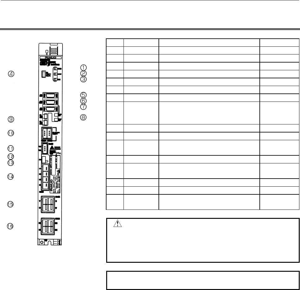
6.CONNECTOR LOCATIONS FOR β SERIES AMPLIFIER (SVU40, SVU-80) CONNECTION B-65232EN/03
- 266 -
6.3 PWM INTERFACE (SVU-40, SVU-80)
Name Description Remarks
<1> POWER Control power status indicator LED
<2> DRDY Activation status indicator LED
<3> ALM Alarm status indicator LED
<4> FUSE Fuse for 24V power supply
<5> JX5/CHK Connector for ESP and signal checking
<6> JS1B Connector for NC interface
<7> JF1/ENC Connector for Pulsecoder
<8> CX5X/5Y Battery connector for ABS Pulsecoder
For servo
check pin
board
<9> CX18X/18Y Connector for fan motor
<10> CX19A/19B 24V power input/output connector
<11> CX20
Connector for separated regenerative
resistor (OH alarm)
(Note)
<12> DC link charge indicator LED (Warning)
<13> SW
Switch for regeneration error detection
circuit changeover
<14> CX21 Connector for primary power input
<15> CX22 Connector for motor power
<16> CX23
Connector for separated regenerative
resistor (resistor line)
(Note)
WARNING
It is dangerous to touch any cables and
components inside the module while this LED is lit.
Never touch components or cables while this LED
is lit.
NOTE
Refer to Section 8.5 for details.
Contents Summary of Servo Motor Beta Series Descriptions
- Page 1GE Fanuc Automation Europe Computer Numerical Controls Fanuc AC Servo Motor β Series Descriptions Manual B-65232EN/03 TECHNOLOGY AND MORE
- Page 2Ȧ No part of this manual may be reproduced in any form. Ȧ All specifications and designs are subject to change without notice. In this manual we have tried as much as possible to describe all the various matters. However, we cannot describe all the matters which must not be done, or which cannot be
- Page 3B-65232EN/03 SAFETY PRECAUTIONS SAFETY PRECAUTIONS This "Safety Precautions" section describes the precautions which must be observed to ensure safety when using FANUC servo motors and servo amplifiers. Users of any servo motor or amplifier model are requested to read the "Safety Precautions" carefu
- Page 4SAFETY PRECAUTIONS B-65232EN/03 1.1 DEFINITION OF WARNING, CAUTION, AND NOTE This manual includes safety precautions for protecting the user and preventing damage to the machine. Precautions are classified into Warning and Caution according to their bearing on safety. Also, supplementary information
- Page 5B-65232EN/03 SAFETY PRECAUTIONS 1.2 FANUC SERVO MOTOR β SERIES 1.2.1 Warning WARNING - Be safely dressed when handling a motor. Wear safety shoes or gloves when handling a motor as you may get hurt on any edge or protrusion on it or electric shocks. - Use a crane or lift to move a motor from one pla
- Page 6SAFETY PRECAUTIONS B-65232EN/03 WARNING - Connect power wires securely so that they will not get loose. A failure to observe this caution may cause a wire to be disconnected, resulting in a ground fault, short circuit, or electric shock. - Do not supply the power to the motor while any terminal is e
- Page 7B-65232EN/03 SAFETY PRECAUTIONS - Ensure that motors and related components are mounted securely. If a motor or its component slips out of place or comes off when the motor is running, it is very dangerous. - Be careful not get your hair or cloths caught in a fan. Be careful especially for a fan use
- Page 8SAFETY PRECAUTIONS B-65232EN/03 1.2.2 Caution CAUTION - FANUC motors are designed for use with machines. Do not use them for any other purpose. If a FANUC motor is used for an unintended purpose, it may cause an unexpected symptom or trouble. If you want to use a motor for an unintended purpose, pre
- Page 9B-65232EN/03 SAFETY PRECAUTIONS 1.2.3 Note NOTE - Do not step or sit on a motor. If you step or sit on a motor, it may get deformed or broken. Do not put a motor on another unless they are in packages. - When storing a motor, put it in a dry (non-condensing) place at room temperature (0 to 40°°C). I
- Page 10SAFETY PRECAUTIONS B-65232EN/03 NOTE - Use a motor under an appropriate environmental condition. Using a motor in an adverse environment may cause a failure or trouble in it. Refer to their respective specification manuals for details of the operating and environmental conditions for motors. - Do no
- Page 11B-65232EN/03 SAFETY PRECAUTIONS 1.3 FANUC SERVO AMPLIFIER β SERIES 1.3.1 Warnings and Cautions Relating to Mounting 1.3.1.1 Warning WARNING - Check the specification code of the amplifier. Check that the delivered amplifier is as originally ordered. - Mount a ground fault interrupter. To guard again
- Page 12SAFETY PRECAUTIONS B-65232EN/03 WARNING - Do not disassemble the amplifier. - Ensure that the cables used for the power supply lines and power lines are of the appropriate diameter and temperature ratings. - Do not apply an excessively large force to plastic parts. If a plastic section breaks, it ma
- Page 13B-65232EN/03 SAFETY PRECAUTIONS 1.3.1.2 Caution CAUTION - Do not step or sit on the amplifier. Also, do not stack unpacked amplifiers on top of each other. - Use the amplifier in an appropriate environment. See the allowable ambient temperatures and other requirements, given in the corresponding des
- Page 14SAFETY PRECAUTIONS B-65232EN/03 CAUTION - Check that the amplifier is securely mounted in the power magnetics cabinet. If any clearance is left between the power magnetics cabinet and the surface on which the amplifier is mounted, dust entering the gap may build up and prevent the normal operation o
- Page 15B-65232EN/03 SAFETY PRECAUTIONS 1.3.1.3 Note NOTE - Keep the nameplate clearly visible. - Keep the legend on the nameplate clearly visible. - After unpacking the amplifier, carefully check for any damage. - Mount the amplifier in a location where it can be easily accessed periodic inspection and dai
- Page 16SAFETY PRECAUTIONS B-65232EN/03 1.3.2 Warnings and Cautions Relating to a Pilot Run 1.3.2.1 Warning WARNING - Before turning on the power, check that the cables connected to the power magnetics cabinet and amplifier, as well as the power lines and power supply lines, are securely connected. Also, ch
- Page 17B-65232EN/03 SAFETY PRECAUTIONS 1.3.2.2 Caution CAUTION - Note whether an alarm status relative to the amplifier is displayed at power-up or during operation. If an alarm is displayed, take appropriate action as explained in the maintenance manual. If the work to be done requires that the door of th
- Page 18SAFETY PRECAUTIONS B-65232EN/03 1.3.3 Warnings and Cautions Relating to Maintenance 1.3.3.1 Warning WARNING - Read the maintenance manual carefully and ensure that you are totally familiar with its contents. The maintenance manual describes daily maintenance and the procedures to be followed in the
- Page 19B-65232EN/03 SAFETY PRECAUTIONS WARNING - Notes on replacing the battery of the absolute pulse coder Replace the battery only while the power is on. If the battery is replaced while the power is turned off, the stored absolute positioning data will be lost. Some series servo amplifier modules have b
- Page 20SAFETY PRECAUTIONS B-65232EN/03 1.3.3.2 Caution CAUTION - Ensure that all required components are mounted. When replacing a component or PC board, check that all components, including the snubber capacitor, are correctly mounted. If the snubber capacitor is not mounted, for example, the IPM will be
- Page 21B-65232EN/03 SAFETY PRECAUTIONS 1.3.3.3 Note NOTE - Ensure that the battery connector is correctly inserted. If the power is shut off while the battery connector is not connected correctly, the absolute position data for the machine will be lost. - Store the manuals in a safe place. The manuals shou
- Page 22
- Page 23B-65232EN/03 TABLE OF CONTENTS TABLE OF CONTENTS SAFETY PRECAUTIONS .......................................................................... s-1 I. DESCRIPTIONS FOR FANUC AC SERVO MOTOR β series 1 OVERVIEW ............................................................................................
- Page 24TABLE OF CONTENTS B-65232EN/03 5.2.5 Installation Method (IEC34-7) .............................................................................. 43 5.2.6 Heat Protection (IEC34-11)................................................................................... 43 6 EMC DIRECTIVE ................
- Page 25B-65232EN/03 TABLE OF CONTENTS 2.3 SPEED-TORQUE CHARACTERISTICS WHEN HRV1 CONTROL AND AN I/O Link β AMPLIFIER ARE USED ........................................................81 2.4 OUTLINE DRAWINGS ................................................................................82 III. FANUC AC SERV
- Page 26TABLE OF CONTENTS B-65232EN/03 2.6.3 AC Line Filter...................................................................................................... 139 2.7 CONNECTOR............................................................................................140 3 SPECIFICATIONS.................
- Page 27B-65232EN/03 TABLE OF CONTENTS 8 CAUTIONS FOR SAFETY STANDARDS RELATED TO AMPLIFIER INSTALLATION..................................................................................181 8.1 OVERVIEW ...............................................................................................182 8.2 ST
- Page 28TABLE OF CONTENTS B-65232EN/03 2 CONNECTOR LOCATIONS FOR β SERIES AMPLIFIER .................220 2.1 FSSB INTERFACE (SVU4, SVU-12, SVU-20) ..........................................221 2.2 I/O Link INTERFACE (SVU4, SVU-12, SVU-20) .......................................222 2.3 PWM INTERFACE (SVU4, S
- Page 29B-65232EN/03 TABLE OF CONTENTS 5.2.1 Three-phase Power Input..................................................................................... 259 5.2.2 Single-phase Power Input .................................................................................... 260 5.3 PWM INTERFACE (SVU40, SVU-
- Page 30TABLE OF CONTENTS B-65232EN/03 10.4 SKIP SIGNAL INTERFACE .......................................................................292 10.4.1 High-Speed Skip Signal Input Specification ....................................................... 292 11 EXTERNAL PULSE INPUT (ONLY FOR I/O Link INTERFACE) ...
- Page 31I. DESCRIPTIONS FOR FANUC AC SERVO MOTOR β series
- Page 32
- Page 33B-65232EN/03 DESCRIPTIONS FOR FANUC AC SERVO MOTOR β series 1.OVERVIEW 1 OVERVIEW The FANUC AC SERVO MOTOR β series is an economical AC servo motor series most suitable for positioning peripheral devices of industrial machines and machine tools, and has the features listed below. SERVO MOTOR βM seri
- Page 342.NOTES ON USE DESCRIPTIONS FOR FANUC AC SERVO MOTOR β series B-65232EN/03 2 NOTES ON USE -4-
- Page 35B-65232EN/03 DESCRIPTIONS FOR FANUC AC SERVO MOTOR β series 2.NOTES ON USE 2.1 COMPATIBLE AMPLIFIERS 2.1.1 Amplifiers Suitable for the βM series Servo Motors The FANUC AC SERVO MOTOR βM series can be driven by the FANUC SERVO AMPLIFIER β series or αi series. Connection Motor model Series Model Inter
- Page 362.NOTES ON USE DESCRIPTIONS FOR FANUC AC SERVO MOTOR β series B-65232EN/03 NOTE 1 For information about the β series servo amplifier unit, refer to Part IV of this manual. For information about the αi series servo amplifier module, refer to FANUC AC SERVO AMPLIFIER αi series DESCRIPTIONS (B-65282EN)
- Page 37B-65232EN/03 DESCRIPTIONS FOR FANUC AC SERVO MOTOR β series 2.NOTES ON USE 2.1.2 Amplifiers Suitable for the β series Servo Motors The FANUC AC SERVO MOTOR β series can be driven by the FANUC SERVO AMPLIFIER β series or α series. Connection Motor model Series Model Interface Specification axis FSSB
- Page 382.NOTES ON USE DESCRIPTIONS FOR FANUC AC SERVO MOTOR β series B-65232EN/03 Connection Motor model Series Model Interface Specification axis FSSB A06B-6093-H112 β series servo amplifier 1-axis SVU-20 I/O Link A06B-6093-H152 unit TYPE B A06B-6093-H102 FSSB A06B-6096-H102 1-axis SVM1-20 TYPE A, B A06B-
- Page 39B-65232EN/03 DESCRIPTIONS FOR FANUC AC SERVO MOTOR β series 2.NOTES ON USE NOTE 1 For information about the β series servo amplifier unit, refer to Part IV of this manual. For information about the αi series servo amplifier module, refer to FANUC AC SERVO AMPLIFIER αi series DESCRIPTIONS (B-65282EN)
- Page 402.NOTES ON USE DESCRIPTIONS FOR FANUC AC SERVO MOTOR β series B-65232EN/03 2.2 INSTALLATION The servo motor contains a precision detector, and is carefully machined and assembled to provide the required precision. Pay attention to the following items to maintain the precision and prevent damage to t
- Page 41B-65232EN/03 DESCRIPTIONS FOR FANUC AC SERVO MOTOR β series 2.NOTES ON USE 2.3 COUPLING A precision detector is directly attached to the shaft end of the servo motor. Pay attention to the following items to prevent damage to the detector. (1) When connecting the power transmission elements such as a
- Page 422.NOTES ON USE DESCRIPTIONS FOR FANUC AC SERVO MOTOR β series B-65232EN/03 (5) Even when a light impact needs to be applied to remove the jointed taper surface, for example, just strike it softly in the radial direction. Do not apply impact in the axial direction. (6) Suppress the rotary unbalance o
- Page 43B-65232EN/03 DESCRIPTIONS FOR FANUC AC SERVO MOTOR β series 2.NOTES ON USE 2.4 AXIS LOAD The allowable axis load of the motor shaft is as follows. Front bearing Motor model Radial load Axial load (reference) βM0.2/4000 6.4kgf 4kgf 699 βM0.3/4000 βM0.4/4000 βM0.5/4000 20kgf 5kgf 6902 βM1/4000 β1/3000
- Page 442.NOTES ON USE DESCRIPTIONS FOR FANUC AC SERVO MOTOR β series B-65232EN/03 2.5 ENVIRONMENT (1) Ambient temperature The ambient temperature should be -10 to 40°C. When operating the machine at a higher temperature, it is necessary to lower the output power so that the motor temperature does not excee
- Page 45B-65232EN/03 DESCRIPTIONS FOR FANUC AC SERVO MOTOR β series 2.NOTES ON USE (4) Drip-proof environment The protection form for a single motor unit satisfies IP65 of the IEC standards (equivalent to JP65, dust-proof and jet-proof type, of JIS C4004-1980, code for revolving electric machines) These sta
- Page 462.NOTES ON USE DESCRIPTIONS FOR FANUC AC SERVO MOTOR β series B-65232EN/03 (c) When the motor connector is up, the cutting fluid is collected in the cable connector through the cable. Turn the motor connector sideways or downward as far as possible. Most of the defects caused by the cutting fluid ha
- Page 47B-65232EN/03 DESCRIPTIONS FOR FANUC AC SERVO MOTOR β series 2.NOTES ON USE (5) Shaft attachment section requirements The shaft of the motor has an oil seal to prevent foreign matter such as oil from entering the motor. Given that motors tend to be used in a wide range of environments, however, prote
- Page 482.NOTES ON USE DESCRIPTIONS FOR FANUC AC SERVO MOTOR β series B-65232EN/03 2.6 ACCEPTANCE AND STORAGE When the servo motor is delivered, check the following items. • The motor meets the specifications. (Specifications of the model/shaft/detector) • Damage caused by the transportation. • The shaft is
- Page 49B-65232EN/03 DESCRIPTIONS FOR FANUC AC SERVO MOTOR β series 3.INSTRUCTIONS 3 INSTRUCTIONS - 19 -
- Page 503.INSTRUCTIONS DESCRIPTIONS FOR FANUC AC SERVO MOTOR β series B-65232EN/03 3.1 DRIVE SHAFT COUPLING There are four methods for connecting the motor shaft to the ball screw: • Direct connection through a flexible coupling • Direct connection through a rigid coupling • Connection through gears • Conne
- Page 51B-65232EN/03 DESCRIPTIONS FOR FANUC AC SERVO MOTOR β series 3.INSTRUCTIONS (2) Direct connection using a rigid coupling Direct connection using a rigid coupling has the following advantages over direct connection using a flexible coupling: • More economical • The coupling rigidity can be increased.
- Page 523.INSTRUCTIONS DESCRIPTIONS FOR FANUC AC SERVO MOTOR β series B-65232EN/03 (4) Timing belt A timing belt is used in the same cases as gear connection, but in comparison, it has advantages such as low cost and reduced noise during operation, etc. However, it is necessary to correctly understand the c
- Page 53B-65232EN/03 DESCRIPTIONS FOR FANUC AC SERVO MOTOR β series 3.INSTRUCTIONS 3.2 MACHINE MOVEMENT PER 1 REVOLUTION OF MOTOR SHAFT The machine movement per 1 revolution of motor shaft must be determined at the first stage of machine design referring the load torque, load inertia, rapid traverse speed,
- Page 544.SELECTING A MOTOR DESCRIPTIONS FOR FANUC AC SERVO MOTOR β series B-65232EN/03 4 SELECTING A MOTOR When making a motor selection, select an optimal motor from the viewpoints of load conditions, feedrate, increment system, and so forth. This section describes how to calculate the load and other cond
- Page 55B-65232EN/03 DESCRIPTIONS FOR FANUC AC SERVO MOTOR β series 4.SELECTING A MOTOR Condition 3 The frequency of positioning in rapid traverse satisfy to a desired value. The greater the frequency of positioning in rapid traverse, the greater the ratio of acceleration time to the entire operation time.
- Page 564.SELECTING A MOTOR DESCRIPTIONS FOR FANUC AC SERVO MOTOR β series B-65232EN/03 4.1 MOTOR SELECTION When making a motor selection, select an optimal motor from the viewpoints of load conditions, rapid traverse rate, increment system, and so forth. To ensure satisfactory motor selection, the user sho
- Page 57B-65232EN/03 DESCRIPTIONS FOR FANUC AC SERVO MOTOR β series 4.SELECTING A MOTOR 4.1.2 Data Items to be Entered The machine tool builder is to provide the following data: direction of movement, feed mechanism, mechanical specifications, and external position detector. If a particular specification va
- Page 584.SELECTING A MOTOR DESCRIPTIONS FOR FANUC AC SERVO MOTOR β series B-65232EN/03 (3) Mechanical specifications Data in this blank serve as the basis for selecting the motor. Enter these data correctly. (a) Travelling distance of machine per revolution of the motor Enter the travelling of the machine
- Page 59B-65232EN/03 DESCRIPTIONS FOR FANUC AC SERVO MOTOR β series 4.SELECTING A MOTOR (i) Frequency of positioning in rapid traverse Enter the rapid traverse positioning frequency by the number of times per minute. This value is used to check if the motor is overheated or not by a flowing current during a
- Page 604.SELECTING A MOTOR DESCRIPTIONS FOR FANUC AC SERVO MOTOR β series B-65232EN/03 (6) Data to be provided by FANUC (a) Input multiply ratio, command multiply ratio, and flexible feed gear ratio The NC set values required for moving the machine tool at the least input increment values are entered in th
- Page 61B-65232EN/03 DESCRIPTIONS FOR FANUC AC SERVO MOTOR β series 4.SELECTING A MOTOR (b) Position loop gain Fill in this blank with a value which is considered to be settable judging it from the inertia value based on experiences. Since this value is not always applicable due to rigidity, damping constan
- Page 624.SELECTING A MOTOR DESCRIPTIONS FOR FANUC AC SERVO MOTOR β series B-65232EN/03 • Dynamic brake stop distance This is coasting distance when the machine tool is stopped by dynamic braking with both ends of the motor power line shorted, if the machine tool is in trouble. Vm : Rapid traverse rate, mm/
- Page 63B-65232EN/03 DESCRIPTIONS FOR FANUC AC SERVO MOTOR β series 4.SELECTING A MOTOR (7) Coefficients for calculating the dynamic brake stop distance 2 Motor model A B Jm (kgfcms ) -1 -8 -5 βM0.2/4000 8.1×10 5.7×10 1.9×10 -1 -8 -5 βM0.3/4000 3.4×10 4.5×10 3.5×10 -1 -8 -4 βM0.4/4000 2.2×10 4.5×10 1.0×10 -
- Page 644.SELECTING A MOTOR DESCRIPTIONS FOR FANUC AC SERVO MOTOR β series B-65232EN/03 MTB Servo motor selection data table (models for positioning) Machine type Machine model CNC model FANUC Name Item Axis name Specifications of moving object Direction of movement (horizontal, vertical, slant__degrees, ro
- Page 65B-65232EN/03 DESCRIPTIONS FOR FANUC AC SERVO MOTOR β series 4.SELECTING A MOTOR 4.2 CHARACTERISTIC CURVE AND DATA SHEET Performance of each motor model is represented by characteristic curves and data sheet shown below. 4.2.1 Characteristic Curves The typical characteristic curves consist of the fol
- Page 664.SELECTING A MOTOR DESCRIPTIONS FOR FANUC AC SERVO MOTOR β series B-65232EN/03 4.2.2 Data Sheet The data sheet gives the values of motor parameters relating to the performance. The values of parameters are those under the following conditions. • The ambient temperature for the motor is 20°C. • The
- Page 67B-65232EN/03 DESCRIPTIONS FOR FANUC AC SERVO MOTOR β series 4.SELECTING A MOTOR 4.2.3 How to Use Overload Duty Curves The servo motor can be driven out of the continuous operating zone, but intermittently. Duty characteristics shows the Duty (%) and the "ON" time in which motor can be operated under
- Page 685.IEC34 STANDARD DESCRIPTIONS FOR FANUC AC SERVO MOTOR β series B-65232EN/03 5 IEC34 STANDARD - 38 -
- Page 69B-65232EN/03 DESCRIPTIONS FOR FANUC AC SERVO MOTOR β series 5.IEC34 STANDARD 5.1 REQUIREMENTS FOR COMPLIANCE This section describes the conformity of the FANUC AC SERVO MOTOR β series and βM series to the IEC34 standard. The IEC34 standard can be satisfied by using a motor having a nameplate bearing
- Page 705.IEC34 STANDARD DESCRIPTIONS FOR FANUC AC SERVO MOTOR β series B-65232EN/03 [β series] Plug connector specification Cable clamp specification Motor model Manufacturer [FANUC specification] [FANUC specification] Straight H/MS3106A18-10S-D-T(10) type [A63L-0001-0648/61810SH] H/MS3057-10A(10) HIROSE P
- Page 71B-65232EN/03 DESCRIPTIONS FOR FANUC AC SERVO MOTOR β series 5.IEC34 STANDARD 5.2 APPROVAL SPECIFICATIONS 5.2.1 Rotational Speed (IEC34-1) Each model's maximum allowable speed is as shown below. The maximum allowable speeds are determined from the viewpoint of speed alone within the range in which th
- Page 725.IEC34 STANDARD DESCRIPTIONS FOR FANUC AC SERVO MOTOR β series B-65232EN/03 5.2.3 Protection Mode (IEC34-5) The protection mode defined by IEC34-5 is as follows: Motor model IP Approval condition βM0.4/4000 βM0.5/4000 65 A specified connector needs to be used. βM1/4000 β1/3000 β2/3000 A specified c
- Page 73B-65232EN/03 DESCRIPTIONS FOR FANUC AC SERVO MOTOR β series 5.IEC34 STANDARD 5.2.5 Installation Method (IEC34-7) A motor can be installed using any of the following methods: IMB5 : The motor is installed by using a flange, with the shaft oriented horizontally (from the back). IMV1 : The motor is ins
- Page 746.EMC DIRECTIVE DESCRIPTIONS FOR FANUC AC SERVO MOTOR β series B-65232EN/03 6 EMC DIRECTIVE The β series servo motors comply with the EMC directive. To make the entire machine compliant to the EMC directive, the necessary measures must be taken according to the guideline published by FANUC (document
- Page 75B-65232EN/03 DESCRIPTIONS FOR FANUC AC SERVO MOTOR β series 7.FEEDBACK DETECTOR 7 FEEDBACK DETECTOR - 45 -
- Page 767.FEEDBACK DETECTOR DESCRIPTIONS FOR FANUC AC SERVO MOTOR β series B-65232EN/03 7.1 BUILT-IN DETECTOR All servo motors feature a pulse coder (optical rotary encoder). The pulse coder outputs position information and an alarm signal. The βM series motors incorporate pulse coders designed to the speci
- Page 77B-65232EN/03 DESCRIPTIONS FOR FANUC AC SERVO MOTOR β series 7.FEEDBACK DETECTOR 7.2 ABSOLUTE-TYPE PULSE CODER When the CNC is turned off, the pulse coder position detection function is backed up by battery. So, when the CNC is next turned on, the operator does not have to perform reference position
- Page 787.FEEDBACK DETECTOR DESCRIPTIONS FOR FANUC AC SERVO MOTOR β series B-65232EN/03 7.3 EXTERNAL POSITION DETECTOR For detecting a position by attaching directly to a ball screw or a machine, use an external (separate type) position detector. Pay attention to the following items when using the external
- Page 79B-65232EN/03 DESCRIPTIONS FOR FANUC AC SERVO MOTOR β series 7.FEEDBACK DETECTOR 7.4 DETECTOR SIGNAL OUTPUT The following table lists the pin assignment of the β series servo motor output signals and the signals on each model's connectors. β1/3000 βM0.4/4000 βM0.2/4000 β2/3000 Motor model βM0.5/4000
- Page 808.BUILT-IN BRAKE DESCRIPTIONS FOR FANUC AC SERVO MOTOR β series B-65232EN/03 8 BUILT-IN BRAKE β series servo motors have models that contain a holding brake to prevent falling of a vertical axis. Motors with a built-in brake have different outlines and weight from other types of motors. For their ou
- Page 81B-65232EN/03 DESCRIPTIONS FOR FANUC AC SERVO MOTOR β series 8.BUILT-IN BRAKE 8.1 BRAKE SPECIFICATIONS The specifications of built-in brakes for βM series servo motors are listed below. β M0.2/4000 β M0.4/4000 Item Unit β M1/4000 β M0.3/4000 β M0.5/4000 Nm 0.32 0.65 1.2 Brake torque kgf⋅cm 3.3 6.6 12
- Page 828.BUILT-IN BRAKE DESCRIPTIONS FOR FANUC AC SERVO MOTOR β series B-65232EN/03 8.2 FIGURES OF CONNECTORS The figures and pin arrangements of brake connectors are shown below. [Models βM0.2 and βM0.3] Connection : B2=BK, B3=BK B1 B2 B3 (Connected to the power connector) (A1=U, A2=V, A3=W, B1=GND) A1 A2
- Page 83B-65232EN/03 DESCRIPTIONS FOR FANUC AC SERVO MOTOR β series 8.BUILT-IN BRAKE 8.3 CONNECTION OF THE BRAKES Configure a brake circuit by referencing the brake connection diagram, notes, and recommended components described below. [Models βM0.2 and βM0.3] Circuit breaker, etc Motor coil Servo amplifier
- Page 848.BUILT-IN BRAKE DESCRIPTIONS FOR FANUC AC SERVO MOTOR β series B-65232EN/03 Notes (1) Use 24 VDC as the brake power for the βM series servo motor. AC power decreased by a transformer and full-wave rectified to 24 Vrms can also be used. (2) For the brake power, use a power system different from the
- Page 85B-65232EN/03 DESCRIPTIONS FOR FANUC AC SERVO MOTOR β series 8.BUILT-IN BRAKE [Models β1 to β6] Circuit breaker, etc Motor coil Servo amplifier 200VAC Relay Ground Coil (to motor body) Spark killer Brake coil Contact (No polarity is applied.) Surge absorber Ground 100VAC (to motor body) Notes (1) Use
- Page 869.CONNECTORS DESCRIPTIONS FOR FANUC AC SERVO MOTOR β series B-65232EN/03 9 CONNECTORS - 56 -
- Page 87B-65232EN/03 DESCRIPTIONS FOR FANUC AC SERVO MOTOR β series 9.CONNECTORS 9.1 SPECIFICATIONS OF MOTOR CONNECTORS With the FANUC AC SERVO MOTOR β series, TÜV-approved connectors are used for power and brake to ensure conformity with the IEC34 standard. The table below indicates the specifications of t
- Page 889.CONNECTORS DESCRIPTIONS FOR FANUC AC SERVO MOTOR β series B-65232EN/03 The standard receptacle connectors for models β1 to β6 do not exactly satisfy the MS standard in that the connectors are waterproof as single units, and their exterior color is black. However, their sizes and shapes are compati
- Page 89B-65232EN/03 DESCRIPTIONS FOR FANUC AC SERVO MOTOR β series 9.CONNECTORS 9.2 βM0.2 AND βM0.3 CONNECTORS ON CABLE SIDE 9.2.1 Specifications of βM0.2 and βM0.3 Connectors for Power and Brake The specifications of the power connector (cable side) for βM0.2 and βM0.3 are indicated below. The connector i
- Page 909.CONNECTORS DESCRIPTIONS FOR FANUC AC SERVO MOTOR β series B-65232EN/03 9.2.2 Specifications of βM0.2 and βM0.3 Connectors for Signal The specifications of the signal connector (cable side) for βM0.2 and βM0.3 are indicated below. The connector is not drip-proof. For signal Housing specification 1-
- Page 91B-65232EN/03 DESCRIPTIONS FOR FANUC AC SERVO MOTOR β series 9.CONNECTORS NOTE 1 When the recommended wire (wire size from 0.18 to 0.5 mm2) is used only with D-2 contact of M size, the dedicated crimping tool indicated above is necessary. When the standard crimping tool for the D-2 contact is used, c
- Page 929.CONNECTORS DESCRIPTIONS FOR FANUC AC SERVO MOTOR β series B-65232EN/03 9.3 βM0.4 TO βM1 CONNECTORS ON CABLE SIDE 9.3.1 Specifications of βM0.4 to βM1 Connectors for Power and Brake The specifications of the power and brake connectors (cable side) for βM0.4 to βM1 are indicated below. The connector
- Page 93B-65232EN/03 DESCRIPTIONS FOR FANUC AC SERVO MOTOR β series 9.CONNECTORS 9.3.2 Specifications of βM0.4 to βM1 Connectors for Signal The specifications of the signal connector (cable side) for βM0.4 and βM1 are indicated below. The connector is drip-proof when fitted. For signal Connector body Straig
- Page 949.CONNECTORS DESCRIPTIONS FOR FANUC AC SERVO MOTOR β series B-65232EN/03 9.4 β1 TO β6 CONNECTORS ON CABLE SIDE 9.4.1 Specifications of β1 to β6 Connectors for Power and Brake (TÜV-certified and Waterproof Type) To satisfy the IEC34 standard, the TÜV-certified waterproof plug connectors and cable cla
- Page 95B-65232EN/03 DESCRIPTIONS FOR FANUC AC SERVO MOTOR β series 9.CONNECTORS Example cable connections Plug (straight Cable clamp Plug (elbow type) Cable seal adapter (straight Receptacle connector (motor Cable seal adapter (90°° elbow type) Plug (single-unit block ) Conduit hose seal (straight ) Condui
- Page 969.CONNECTORS DESCRIPTIONS FOR FANUC AC SERVO MOTOR β series B-65232EN/03 9.4.2 Specifications of β1 to β6 Connectors for Power and Brake (Not TÜV-compliant and Waterproof Type) When the IEC34 standard need not be satisfied, the waterproof plug connectors and cable clamps (not TÜV-compliant) indicate
- Page 97B-65232EN/03 DESCRIPTIONS FOR FANUC AC SERVO MOTOR β series 9.CONNECTORS 9.4.3 Specifications of β1 to β6 Connectors for Power and Brake (Not TÜV-compliant and Non-waterproof Type) When the IEC34 standard need not be satisfied, and waterproofness is not required, the non-waterproof plug connectors a
- Page 989.CONNECTORS DESCRIPTIONS FOR FANUC AC SERVO MOTOR β series B-65232EN/03 9.4.4 Specifications of β1 to β6 Connectors for Signal D-sub connectors are used as standard for the signal lines of the models β1 to β6. The D-Sub connectors are not water-proof. To ensure waterproofness, a special connector c
- Page 99II. FANUC AC SERVO MOTOR βM series
- Page 100
- Page 101B-65232EN/03 FANUC AC SERVO MOTOR β series 1.TYPES OF MOTORS AND DESIGNATION 1 TYPES OF MOTORS AND DESIGNATION The types and specifications of βM series servo motors are described as follows. Models βM0.2/4000 and βM0.3/4000 A06B-011x-Byzz x 1 : Model βM0.2/4000 2 : Model βM0.3/4000 y 0 : Straight s
- Page 1021.TYPES OF MOTORS AND DESIGNATION FANUC AC SERVO MOTOR β series B-65232EN/03 NOTE 1 The resolution of the βA64B and βI64B pulse coders is 65,536/rev. 2 The standard shafts used for βM series motor are straight shafts. Use a straight shaft as far as circumstances, such as the delivery time and mainte
- Page 103B-65232EN/03 FANUC AC SERVO MOTOR β series 2.SPECIFICATIONS AND CHARACTERISTICS 2 SPECIFICATIONS AND CHARACTERISTICS - 73 -
- Page 1042.SPECIFICATIONS AND CHARACTERISTICS FANUC AC SERVO MOTOR β series B-65232EN/03 2.1 TYPE OF MOTORS AND SPECIFICATIONS Item Unit β M0.2/4000 β M0.3/4000 β M0.4/4000 β M0.5/4000 β M1/4000 W 50 100 125 200 400 Output HP 0.07 0.13 0.17 0.3 0.5 Nm 0.16 0.32 0.4 0.65 1.2 Rated torque at stall kgfcm 1.6 3.
- Page 105B-65232EN/03 FANUC AC SERVO MOTOR β series 2.SPECIFICATIONS AND CHARACTERISTICS 2.2 CHARACTERISTIC CURVE AND DATA SHEET See Section 4.2 of Part I of this manual for details of each item. (1) Speed - torque characteristics Typical characteristics of speed and output torque are indicated. The data cur
- Page 1062.SPECIFICATIONS AND CHARACTERISTICS FANUC AC SERVO MOTOR β series B-65232EN/03 Model βM0.2/4000 Specification : A06B-0111-Bxxx Speed - torque characteristics Over load duty characteristics 0.6 100 90 0.5 110% 80 70 120% 0.4 60 130% Torque (Nm) Duty (time %) Intermittent operating 140% 0.3 50 150% 4
- Page 107B-65232EN/03 FANUC AC SERVO MOTOR β series 2.SPECIFICATIONS AND CHARACTERISTICS Model βM0.3/4000 Specification : A06B-0112-Bxxx Speed - torque characteristics Over load duty characteristics 1.2 100 90 1 110% 80 70 120% 0.8 60 130% Torque (Nm) Duty (time %) Intermittent operating 140% 0.6 50 150% 40
- Page 1082.SPECIFICATIONS AND CHARACTERISTICS FANUC AC SERVO MOTOR β series B-65232EN/03 Model βM0.4/4000 Specification : A06B-0114-Bxxx Speed - torque characteristics Over load duty characteristics 1.2 100 90 1 110% 80 70 120% 0.8 60 130% Torque (Nm) Duty (time %) Intermittent operating 140% 0.6 50 150% 40
- Page 109B-65232EN/03 FANUC AC SERVO MOTOR β series 2.SPECIFICATIONS AND CHARACTERISTICS Model βM0.5/4000 Specification : A06B-0115-Bxxx Speed - torque characteristics Over load duty characteristics 3 100 90 2.5 110% 80 70 120% 2 60 130% Torque (Nm) Duty (time %) Intermittent operating 140% 1.5 50 150% 40 17
- Page 1102.SPECIFICATIONS AND CHARACTERISTICS FANUC AC SERVO MOTOR β series B-65232EN/03 Model βM1/4000 Specification : A06B-0116-Bxxx Speed - torque characteristics Over load duty characteristics 6 100 90 5 110% 80 70 120% 4 60 130% Torque (Nm) Duty (time %) Intermittent operating 140% 3 50 150% 40 170% 2 3
- Page 111B-65232EN/03 FANUC AC SERVO MOTOR β series 2.SPECIFICATIONS AND CHARACTERISTICS 2.3 SPEED-TORQUE CHARACTERISTICS WHEN HRV1 CONTROL AND AN I/O Link β AMPLIFIER ARE USED [Model βM0.2/4000] 0.6 0.5 Torque (Nm) 0.4 Intermittent operating 0.3 0.2 0.1 Continuous operating 0 0 1000 2000 3000 4000 5000 Spee
- Page 1122.SPECIFICATIONS AND CHARACTERISTICS FANUC AC SERVO MOTOR β series B-65232EN/03 2.4 OUTLINE DRAWINGS Model Fig. No. Models βM0.2 and βM0.3 : Outline drawing (standard) Fig.2.4(a) Models βM0.2 and βM0.3 : Outline drawing (with a brake) Fig.2.4(b) Models βM0.2 and βM0.3 : Shaft option Fig.2.4(c) Model
- Page 113B-65232EN/03 FANUC AC SERVO MOTOR β series 2.SPECIFICATIONS AND CHARACTERISTICS Fig.2.4(a) Models βM0.2 and βM0.3 : Outline drawing (standard) - 83 -
- Page 1142.SPECIFICATIONS AND CHARACTERISTICS FANUC AC SERVO MOTOR β series B-65232EN/03 Fig.2.4(b) Models βM0.2 and βM0.3 : Outline drawing (with a brake) - 84 -
- Page 115B-65232EN/03 FANUC AC SERVO MOTOR β series 2.SPECIFICATIONS AND CHARACTERISTICS Fig.2.4(c) Models βM0.2 and βM0.3 : Shaft option - 85 -
- Page 1162.SPECIFICATIONS AND CHARACTERISTICS FANUC AC SERVO MOTOR β series B-65232EN/03 Fig.2.4(d) Models βM0.4, βM0.5, and βM1 : Outline drawing (standard) - 86 -
- Page 117B-65232EN/03 FANUC AC SERVO MOTOR β series 2.SPECIFICATIONS AND CHARACTERISTICS Fig.2.4(e) Models βM0.4, βM0.5, and βM1 : Outline drawing (with a brake) - 87 -
- Page 1182.SPECIFICATIONS AND CHARACTERISTICS FANUC AC SERVO MOTOR β series B-65232EN/03 Fig.2.4(f) Models βM0.4 and βM0.5: Shaft option - 88 -
- Page 119B-65232EN/03 FANUC AC SERVO MOTOR β series 2.SPECIFICATIONS AND CHARACTERISTICS Fig.2.4(g) Model βM1: Shaft option - 89 -
- Page 1202.SPECIFICATIONS AND CHARACTERISTICS FANUC AC SERVO MOTOR β series B-65232EN/03 Fig.2.4(h) Models βM0.4, βM0.5, and βM1 : Connector mating diagram (elbow) - 90 -
- Page 121B-65232EN/03 FANUC AC SERVO MOTOR β series 2.SPECIFICATIONS AND CHARACTERISTICS Fig.2.4(i) Models βM0.4, βM0.5, and βM1 : Connector mating diagram (straight) - 91 -
- Page 122
- Page 123III. FANUC AC SERVO MOTOR β series
- Page 124
- Page 125B-65232EN/03 FANUC AC SERVO MOTOR β series 1.TYPES OF MOTORS AND DESIGNATION 1 TYPES OF MOTORS AND DESIGNATION The types and specifications of β series servo motors are described as follows. Models β1/3000, β2/3000, β3/3000, and β6/2000 A06B-00xx-Byzz xx 31 : Model β1/3000 32 : Model β2/3000 33 : Mo
- Page 1262.SPECIFICATIONS AND CHARACTERISTICS FANUC AC SERVO MOTOR β series B-65232EN/03 2 SPECIFICATIONS AND CHARACTERISTICS - 96 -
- Page 127B-65232EN/03 FANUC AC SERVO MOTOR β series 2.SPECIFICATIONS AND CHARACTERISTICS 2.1 TYPE OF MOTORS AND SPECIFICATIONS Item Unit β 1/3000 β 2/3000 β 3/3000 β 6/2000 kW 0.3 0.5 0.5 0.9 Output HP 0.4 0.67 0.67 1.2 Nm 1 2 3 6 Rated torque at stall kgfcm 10 20 30 60 -1 Rated rotation speed min 3000 3000
- Page 1282.SPECIFICATIONS AND CHARACTERISTICS FANUC AC SERVO MOTOR β series B-65232EN/03 2.2 CHARACTERISTIC CURVE AND DATA SHEET See Section 4.2 of Part I of this manual for details of each item. (1) Speed - torque characteristics Typical characteristics of speed and output torque are indicated. The data cur
- Page 129B-65232EN/03 FANUC AC SERVO MOTOR β series 2.SPECIFICATIONS AND CHARACTERISTICS Model β1/3000 Specification : A06B-0031-Bxxx Speed - torque characteristics Over load duty characteristics 4 100 90 110% 80 3 120% 70 60 130% Torque (Nm) Duty (time %) Intermittent operating 140% 2 50 150% 40 170% 30 1 2
- Page 1302.SPECIFICATIONS AND CHARACTERISTICS FANUC AC SERVO MOTOR β series B-65232EN/03 Model β2/3000 Specification : A06B-0032-Bxxx Speed - torque characteristics Over load duty characteristics 8 100 90 110% 80 6 120% 70 60 130% Torque (Nm) Duty (time %) Intermittent operating 140% 4 50 150% 40 170% 30 2 2
- Page 131B-65232EN/03 FANUC AC SERVO MOTOR β series 2.SPECIFICATIONS AND CHARACTERISTICS Model β3/3000 Specification : A06B-0033-Bxxx Speed - torque characteristics Over load duty characteristics 10 100 90 110% 8 80 70 120% 6 60 130% Torque (Nm) Duty (time %) Intermittent operating 140% 50 150% 4 40 170% 30
- Page 1322.SPECIFICATIONS AND CHARACTERISTICS FANUC AC SERVO MOTOR β series B-65232EN/03 Model β6/2000 Specification : A06B-0034-Bxxx Speed - torque characteristics Over load duty characteristics 20 100 90 80 15 70 60 Torque (Nm) Duty (time %) Intermittent operating 10 50 40 30 5 20 Continuous operating 10 0
- Page 133B-65232EN/03 FANUC AC SERVO MOTOR β series 2.SPECIFICATIONS AND CHARACTERISTICS 2.3 SPEED-TORQUE CHARACTERISTICS FOR HRV CONTROL [Model β1/3000] 4 3 Intermittent operating Torque (Nm) 2 1 Continuous operating 0 0 1000 2000 3000 4000 -1 Speed (min ) [Model β2/3000] 8 6 Torque (Nm) Intermittent operat
- Page 1342.SPECIFICATIONS AND CHARACTERISTICS FANUC AC SERVO MOTOR β series B-65232EN/03 [Model β3/3000] 10 8 6 Torque (Nm) Intermittent operating 4 2 Continuous operating 0 0 1000 2000 3000 4000 Speed (min-1) [Model β6/2000] 20 15 Intermittent operating Torque (Nm) 10 5 Continuous operating 0 0 1000 2000 30
- Page 135B-65232EN/03 FANUC AC SERVO MOTOR β series 2.SPECIFICATIONS AND CHARACTERISTICS 2.4 OUTLINE DRAWINGS Model Fig. No. Models β1 and β2 : Outline drawing (standard) Fig.2.4(a) Models β1 and β2 : Outline drawing (with a brake) Fig.2.4(b) Models β1 and β2 : Shaft option Fig.2.4(c) Models β3 and β6 : Outl
- Page 1362.SPECIFICATIONS AND CHARACTERISTICS FANUC AC SERVO MOTOR β series B-65232EN/03 Fig.2.4(a) Models β1 and β2 : Outline drawing (standard) ON φ115 D.B.C. LESS THAN R0.3 Note SHAFT DIA. RUNOUT MAX 0.02 mm Motor model RABBET DIA. ECCENTRICITY MAX 0.04 mm MOUNTING FACE RUNOUT MAX 0.06 mm MAXIMUM RADIAL L
- Page 137B-65232EN/03 FANUC AC SERVO MOTOR β series 2.SPECIFICATIONS AND CHARACTERISTICS Fig.2.4(c) Models β1 and β2 : Shaft option Standard Straight shaft LESS THAN R0.3 CHAMFERING DETAIL OF NECKING Option (1) Straight shaft with a key DEPTH 10 NECKING Option (2) Taper shaft 1/10 TAPER 1/10 TAPER - 107 -
- Page 1382.SPECIFICATIONS AND CHARACTERISTICS FANUC AC SERVO MOTOR β series B-65232EN/03 Fig.2.4(d) Models β3 and β6 : Outline drawing (standard) ON φ165 D.B.C. NECKING 141 OCTAGON Note SHAFT DIA. RUNOUT MAX 0.02 mm Motor model RABBET DIA. ECCENTRICITY MAX 0.04 mm MOUNTING FACE RUNOUT MAX 0.06 mm MAXIMUM RAD
- Page 139B-65232EN/03 FANUC AC SERVO MOTOR β series 2.SPECIFICATIONS AND CHARACTERISTICS Fig.2.4(f) Models β3 and β6 : Shaft option Standard Straight shaft DETAIL OF NECKING (4 : 1) 2-M4 DEPTH 10 Option (1) Straight shaft with a key NECKING 1/10 TAPER Option (2) Taper shaft 1/10 TAPER - 109 -
- Page 140
- Page 141IV. FANUC AC SERVO AMPLIFIER β series
- Page 142
- Page 143B-65232EN/03 FANUC AC SERVO AMPLIFIER β series 1.OVERVIEW 1 OVERVIEW The main features of servo amplifier β series are as follows: Features not dependent on the interface (1) The servo amplifier β series is integrated with a power supply unit, so that a compact system can be implemented for one or t
- Page 1442.CONFIGURATION FANUC AC SERVO AMPLIFIER β series B-65232EN/03 2 CONFIGURATION Following contents shows an example system configuration having two controlled axes. A separated regenerative discharge unit nay be required to handle large amounts of regenerative energy if the load is particularly heavy
- Page 145B-65232EN/03 FANUC AC SERVO AMPLIFIER β series 2.CONFIGURATION 2.1 FSSB INTERFACE 2.1.1 SVU-4, SVU-12, SVU-20 (Three-phase Power Input) WARNING A circuit breaker, electromagnetic contactor, and AC line filter must be installed. - 115 -
- Page 1462.CONFIGURATION FANUC AC SERVO AMPLIFIER β series B-65232EN/03 2.1.2 SVU-4, SVU-12, SVU-20 (Single-phase Power Input) WARNING A circuit breaker, electromagnetic contactor, and AC line filter must be installed. - 116 -
- Page 147B-65232EN/03 FANUC AC SERVO AMPLIFIER β series 2.CONFIGURATION 2.1.3 SVU-40, SVU-80 (Three-phase Power Input) WARNING A circuit breaker, electromagnetic contactor, and AC line filter must be installed. - 117 -
- Page 1482.CONFIGURATION FANUC AC SERVO AMPLIFIER β series B-65232EN/03 2.1.4 SVU-40, SVU-80 (Single-phase Power Input) WARNING A circuit breaker, electromagnetic contactor, and AC line filter must be installed. - 118 -
- Page 149B-65232EN/03 FANUC AC SERVO AMPLIFIER β series 2.CONFIGURATION 2.2 I/O Link INTERFACE 2.2.1 SVU-4, SVU-12, SVU-20 (Three-phase Power Input) Example of configuration WARNING A circuit breaker, electromagnetic contactor, and AC line filter must be installed. - 119 -
- Page 1502.CONFIGURATION FANUC AC SERVO AMPLIFIER β series B-65232EN/03 2.2.2 SVU-4, SVU-12, SVU-20 (Single-phase Power Input) Example of configuration WARNING A circuit breaker, electromagnetic contactor, and AC line filter must be installed. - 120 -
- Page 151B-65232EN/03 FANUC AC SERVO AMPLIFIER β series 2.CONFIGURATION 2.2.3 SVU-40, SVU-80 (Three-phase Power Input) WARNING A circuit breaker, electromagnetic contactor, and AC line filter must be installed. - 121 -
- Page 1522.CONFIGURATION FANUC AC SERVO AMPLIFIER β series B-65232EN/03 2.2.4 SVU-40, SVU-80 (Single-phase Power Input) WARNING A circuit breaker, electromagnetic contactor, and AC line filter must be installed. - 122 -
- Page 153B-65232EN/03 FANUC AC SERVO AMPLIFIER β series 2.CONFIGURATION 2.3 PWM INTERFACE 2.3.1 SVU-4, SVU-12, SVU-20 (Three-phase Power Input) Example of configuration WARNING A circuit breaker, electromagnetic contactor, and AC line filter must be installed. - 123 -
- Page 1542.CONFIGURATION FANUC AC SERVO AMPLIFIER β series B-65232EN/03 2.3.2 SVU-4, SVU-12, SVU-20 (Single-phase Power Input) Example of configuration WARNING A circuit breaker, electromagnetic contactor, and AC line filter must be installed. - 124 -
- Page 155B-65232EN/03 FANUC AC SERVO AMPLIFIER β series 2.CONFIGURATION 2.3.3 SVU-40, SVU-80 (Three-phase Power Input) WARNING A circuit breaker, electromagnetic contactor, and AC line filter must be installed. - 125 -
- Page 1562.CONFIGURATION FANUC AC SERVO AMPLIFIER β series B-65232EN/03 2.3.4 SVU-40, SVU-80 (Single-phase Power Input) WARNING A circuit breaker, electromagnetic contactor, and AC line filter must be installed. - 126 -
- Page 157B-65232EN/03 FANUC AC SERVO AMPLIFIER β series 2.CONFIGURATION 2.4 METHOD OF CONNECTING THE FAN MOTOR Connect cables of two fan motors to the connector (CX18X, CX18Y) of servo amplifier unit. There is no distinction in CX18X and CX18Y. When the cable is attached or detached to the connector, keep ca
- Page 1582.CONFIGURATION FANUC AC SERVO AMPLIFIER β series B-65232EN/03 2.5 UNIT TYPES AND SPECIFICATIONS Table 2.5(a) Unit types and specifications (1) Model Specification Interface Application SVU-4 A06B-6093-H119 FSSB For a feed axis that requires high precision A06B-6093-H159 I/O Link For positioning tha
- Page 159B-65232EN/03 FANUC AC SERVO AMPLIFIER β series 2.CONFIGURATION β M, β series servo motor) Table 2.5(c) Applicable motor (β Motor 0.2 0.3 0.4 0.5 1 2 3 6 model βM0.2 βM0.3 βM0.4 βM0.5 βM1 Amplifier βM /4000 /4000 /4000 /4000 /4000 model (4A) (4A) (20A) (20A) (20A) β1 β2 β3 β6 β /3000 /3000 /3000 /200
- Page 1602.CONFIGURATION FANUC AC SERVO AMPLIFIER β series B-65232EN/03 Table 2.5(d) Unit types and specifications (2) Classification Name Application Specification Type A: For applications where the sum of the rated motor A81L-0001-0083#3C powers does not exceed 5.4 kW AC line filter Type B: For application
- Page 161B-65232EN/03 FANUC AC SERVO AMPLIFIER β series 2.CONFIGURATION Table 2.5(e) Unit types and specifications (for SVU-4, SVU-12, SVU-20) Classification Name Application Specification Connector Solder type A06B-6073-K212 JX5 : For ESP signal (PWM) Crimp type A06B-6073-K213 Connector Solder type A06B-607
- Page 1622.CONFIGURATION FANUC AC SERVO AMPLIFIER β series B-65232EN/03 WARNING At the power input of the power magnetics cabinet, install a surge absorber between the power lines and between each power line and a ground to protect the unit from a voltage surge caused by lightning. See Section 7.5 for detail
- Page 163B-65232EN/03 FANUC AC SERVO AMPLIFIER β series 2.CONFIGURATION Table 2.5(f) Unit types and specifications (for SVU-40, SVU-80) Classification Name Application Specification Connector CX21: For input power line Crimp type A06B-6093-K311 (common) Connector CX22: For motor power line 2 Crimp type A06B-
- Page 1642.CONFIGURATION FANUC AC SERVO AMPLIFIER β series B-65232EN/03 WARNING At the power input of the power magnetics cabinet, install a surge absorber between the power lines and between each power line and a ground to protect the unit from a voltage surge caused by lightning. See Section 7.5 for detail
- Page 165B-65232EN/03 FANUC AC SERVO AMPLIFIER β series 2.CONFIGURATION Connection method 1 - 135 -
- Page 1662.CONFIGURATION FANUC AC SERVO AMPLIFIER β series B-65232EN/03 Connection method 2 - 136 -
- Page 167B-65232EN/03 FANUC AC SERVO AMPLIFIER β series 2.CONFIGURATION 2.6 CIRCUIT BREAKER, ELECTROMAGNETIC CONTACTOR, AND AC LINE FILTER Main power supply AC line β series servo Circuit MCC 200VAC filter amplifier breaker 220VAC 230VAC 240VAC 50Hz/60Hz β series servo amplifier β series servo amplifier 2.6.
- Page 1682.CONFIGURATION FANUC AC SERVO AMPLIFIER β series B-65232EN/03 Table 2.6.1 Currents drawn by motors operating at continuous rated output Input current Input current Motor model (three-phase input) (single-phase input) (Arms) (Arms) βM0.2/4000 0.2 0.4 βM0.3/4000 0.4 0.9 βM0.4/4000 0.6 1.1 βM0.5/4000
- Page 169B-65232EN/03 FANUC AC SERVO AMPLIFIER β series 2.CONFIGURATION 2.6.2 Electromagnetic Contactor Rating Select an appropriate electromagnetic contactor based on Table 2.6.2. When multiple amplifiers are to be connected to a single electromagnetic contactor (MCC), select an MCC based on the currents on
- Page 1702.CONFIGURATION FANUC AC SERVO AMPLIFIER β series B-65232EN/03 2.7 CONNECTOR Specification : A06B-6093-K311 Connector Part number Manufacturer Use Quantity Remarks name 1-179958-4 (housing) For input power line 1 CX21 AMP Japan, Ltd. Crimp type 316041-2 (contact) (200 VAC input) 4 Specification : A0
- Page 171B-65232EN/03 FANUC AC SERVO AMPLIFIER β series 3.SPECIFICATIONS 3 SPECIFICATIONS - 141 -
- Page 1723.SPECIFICATIONS FANUC AC SERVO AMPLIFIER β series B-65232EN/03 3.1 SPECIFICATIONS Table 3.1 (a) Specifications (common) Item Specifications Voltage: 200 VAC to 240 VAC Three-phase input Allowable voltage fluctuation: +10%, -15% (Note) power supply for motor Frequency: 50 Hz, 60 Hz power Allowable f
- Page 173B-65232EN/03 FANUC AC SERVO AMPLIFIER β series 3.SPECIFICATIONS 3.2 DERATING Motor current derating or output derating is required, depending on the motor used. 3.2.1 For SVU-20 Output derating is required to drive β6/2000, α2/5000i, αM2/5000i, αM3/5000i, αC4/3000i, αC8/2000i, and αC12/2000i with si
- Page 1743.SPECIFICATIONS FANUC AC SERVO AMPLIFIER β series B-65232EN/03 3.2.2 For SVU-40 and SVU-80 Table 3.2.2(a) Three-phase input time Motor specifications Specifications of β series amplifiers SVU-40 and SVU-80 Peak Rated Rated Peak Natural air Motor current current output current Forced air cooling coo
- Page 175B-65232EN/03 FANUC AC SERVO AMPLIFIER β series 3.SPECIFICATIONS Table 3.2.2(b) Single-phase input time Motor specifications Specifications of β series amplifiers SVU-40 and SVU-80 Peak Rated Rated Peak Natural air Motor current current output current Forced air cooling cooling (Ap) (Arms) (kW) (Ap)
- Page 1763.SPECIFICATIONS FANUC AC SERVO AMPLIFIER β series B-65232EN/03 3.3 PROTECTION AND ABNORMALITY DETECTION FUNCTIONS The servo amplifier is provided with the protection and abnormality detection functions indicated below. Determine any alarm status from the diagnostic data displayed by the controller.
- Page 177B-65232EN/03 FANUC AC SERVO AMPLIFIER β series 3.SPECIFICATIONS When an FSSB disconnection alarm is issued, the faulty location can be identified using the check method described below. When an FSSB disconnection alarm is issued, the "LINK" and "READY" LEDs are turned off, and the "ALM" LED is turne
- Page 1783.SPECIFICATIONS FANUC AC SERVO AMPLIFIER β series B-65232EN/03 3.4 NORMAL OPERATING MODE In normal operating mode, the LEDs located on the front of the servo amplifier light as indicated below. Table 3.4 Normal Operating Mode I/O Link interface FSSB interface PWM interface State Description LED dis
- Page 179B-65232EN/03 FANUC AC SERVO AMPLIFIER β series 4.SEPARATED REGENERATIVE DISCHARGE UNIT 4 SEPARATED REGENERATIVE DISCHARGE UNIT - 149 -
- Page 1804.SEPARATED REGENERATIVE DISCHARGE UNIT FANUC AC SERVO AMPLIFIER β series B-65232EN/03 4.1 FOR SVU-4, SVU-12, AND SVU-20 4.1.1 Cases Where a Separated Regenerative Discharge Unit Is Not Required When the amount of regenerative energy produced [J] never exceeds the amounts indicated in Table 4.1, a s
- Page 181B-65232EN/03 FANUC AC SERVO AMPLIFIER β series 4.SEPARATED REGENERATIVE DISCHARGE UNIT - For vertical operation (a) When the SI unit system is used Q = 1.047 × 10 −1 ⋅ Th ⋅ Vm ⋅ ta [ J ] (Expression 2) Th: Upward supporting torque applied by the motor during downward rapid traverse [N⋅m] Vm: Motor s
- Page 1824.SEPARATED REGENERATIVE DISCHARGE UNIT FANUC AC SERVO AMPLIFIER β series B-65232EN/03 4.1.2 Cases Where a Separated Regenerative Discharge Unit Is Required When the amount of regenerative energy produced [J] exceeds the amounts indicated in Table 4.1, the DC link overvoltage alarm is issued. To pre
- Page 183B-65232EN/03 FANUC AC SERVO AMPLIFIER β series 4.SEPARATED REGENERATIVE DISCHARGE UNIT - For vertical operation Amount of regenerative discharge (power [W]) when the duty cycle of downward vertical operation during rapid traverse is D(%) (a) When the SI unit system is used −1 D w = 1.047 × 10 ⋅ Th ⋅
- Page 1844.SEPARATED REGENERATIVE DISCHARGE UNIT FANUC AC SERVO AMPLIFIER β series B-65232EN/03 4.1.3 For SVU-40 and SVU-80 If the amount of regenerative discharge from a servo motor is so large that it exceeds the regenerative discharge capacity of the regenerative discharge resistor built into the servo am
- Page 185B-65232EN/03 FANUC AC SERVO AMPLIFIER β series 4.SEPARATED REGENERATIVE DISCHARGE UNIT Switch setting (for SVU-40, SVU-80) With SVU-40 and SVU-80, four switches are provided on the front of the servo amplifier. Be sure to set the switches to match the resistor used. If the switches are set incorrect
- Page 1864.SEPARATED REGENERATIVE DISCHARGE UNIT FANUC AC SERVO AMPLIFIER β series B-65232EN/03 4.1.4 Notes on Regenerative Discharge Unit Installation WARNING 1 A regenerative discharge resistor may be heated to a temperature from 100°C to 200°C. Be careful not to touch the regenerative discharge resistor.
- Page 187B-65232EN/03 FANUC AC SERVO AMPLIFIER β series 4.SEPARATED REGENERATIVE DISCHARGE UNIT A06B-6093-H401 Upper β SVU A06B-6093-H101 Installation direction A06B-6093-H111 A06B-6093-H151 Regenerative resistor Spacer (accessory) Thick cable Thin cable To connector CX11-2 To connector CX11-6 β SVU A06B-609
- Page 1884.SEPARATED REGENERATIVE DISCHARGE UNIT FANUC AC SERVO AMPLIFIER β series B-65232EN/03 A06B-6093-H402 Front view Side view A Side view B Installation direction Upper * Spacer Wall β SVU-12, -20 connector ABCD A, D: To connector CX11-2 B, C: To connector CX11-6 WARNING 1 A regenerative discharge resi
- Page 189B-65232EN/03 FANUC AC SERVO AMPLIFIER β series 4.SEPARATED REGENERATIVE DISCHARGE UNIT A06B-6089-H500 Panel cut-out Mounting direction M4 screw Terminal side Resistor side WARNING 1 A regenerative discharge resistor may be heated to a temperature from 100°C to 200°C. Be careful not to touch the rege
- Page 1904.SEPARATED REGENERATIVE DISCHARGE UNIT FANUC AC SERVO AMPLIFIER β series B-65232EN/03 A06B-6089-H713 to -H714 - 160 -
- Page 191B-65232EN/03 FANUC AC SERVO AMPLIFIER β series 4.SEPARATED REGENERATIVE DISCHARGE UNIT A06B-6089-H713 to -H714 Panel cut-out WARNING 1 A regenerative discharge resistor may be heated to a temperature from 100°C to 200°C. Be careful not to touch the regenerative discharge resistor. 2 If a regenerativ
- Page 1925.POWER SUPPLY FANUC AC SERVO AMPLIFIER β series B-65232EN/03 5 POWER SUPPLY - 162 -
- Page 193B-65232EN/03 FANUC AC SERVO AMPLIFIER β series 5.POWER SUPPLY 5.1 INPUT POWER SUPPLY 5.1.1 Three-phase Input Power Supply for Motor Power - Nominal rated voltage: 200 to 240 VAC - Allowable voltage fluctuation: -15% to +10% - Frequency: 50/60 Hz - Allowable frequency fluctuation: ±2 Hz - Power suppl
- Page 1945.POWER SUPPLY FANUC AC SERVO AMPLIFIER β series B-65232EN/03 5.2 POWER SUPPLY RATINGS 5.2.1 Three-phase Input Power Supply Ratings for Motor Power (1) The power supply rating necessary when using multiple servo motors can be determined by summing the rating of the power supplies required by the ind
- Page 195B-65232EN/03 FANUC AC SERVO AMPLIFIER β series 5.POWER SUPPLY 5.3 POWER TRANSFORMER FOR EXPORTS Use power transformer for an export when this servo amplifier unit is used at a site where the line voltage is other than 200 to 240 VAC. 5.3.1 Specification Table 5.3.1 Specification of power transformer
- Page 1965.POWER SUPPLY FANUC AC SERVO AMPLIFIER β series B-65232EN/03 5.3.2 How to Select a Transformer Select a transformer according to the load condition and the model of the motor for which the transformer is used. Each transformer has secondary winding taps for three amplifiers so that it can be connec
- Page 197B-65232EN/03 FANUC AC SERVO AMPLIFIER β series 6.HEAT DISSIPATION 6 HEAT DISSIPATION Heat dissipation of β series amplifier is as follows : Table 6.1 Total heat dissipation of each servo amplifier β series Total amount Residual amount of heat in the of heat cabinet (W) Ordering number Interface diss
- Page 1987.INSTALLATION CONDITIONS AND NOTES FANUC AC SERVO AMPLIFIER β series B-65232EN/03 7 INSTALLATION CONDITIONS AND NOTES - 168 -
- Page 199B-65232EN/03 FANUC AC SERVO AMPLIFIER β series 7.INSTALLATION CONDITIONS AND NOTES 7.1 ENVIRONMENTAL CONDITIONS Install a β setting servo amplifier in a completely closed cabinet so that the environment conditions indicated below can be satisfied. (1) Ambient Temperature Ambient temperature 0 to 55°
- Page 2007.INSTALLATION CONDITIONS AND NOTES FANUC AC SERVO AMPLIFIER β series B-65232EN/03 7.2 SELECTING A GROUND FAULT INTERRUPTER To protect against electric shocks, be sure to install a ground fault interrupter at the input section of the machine. The β series servo amplifier drives a motor by means of t
- Page 201B-65232EN/03 FANUC AC SERVO AMPLIFIER β series 7.INSTALLATION CONDITIONS AND NOTES 7.3 NOISE PROTECTION 7.3.1 Separation of Signal Lines If a power cable and signal cable run close to each other, noise can be induced. So, ensure that a power cable is separated from a signal cable. When a power cable
- Page 2027.INSTALLATION CONDITIONS AND NOTES FANUC AC SERVO AMPLIFIER β series B-65232EN/03 Cabinet Spindle Servo Control unit amplifier amplifier Cable of group B Duct To operator's panel, motor, etc. Cable of group A Section of duct Group A Group B Shielding plate - 172 -
- Page 203B-65232EN/03 FANUC AC SERVO AMPLIFIER β series 7.INSTALLATION CONDITIONS AND NOTES 7.3.2 Grounding A CNC machine tool has three separate ground systems: (1) Signal ground (SG) system The signal ground (SG) system provides the reference potential (0V) for the electrical signal system. (2) Frame groun
- Page 2047.INSTALLATION CONDITIONS AND NOTES FANUC AC SERVO AMPLIFIER β series B-65232EN/03 7.3.3 Noise Suppressor The AC/DC solenoid and relay are used in the power magnetics cabinet. A high pulse voltage is caused by coil inductance when these devices are turned on or off. This pulse voltage induced throug
- Page 205B-65232EN/03 FANUC AC SERVO AMPLIFIER β series 7.INSTALLATION CONDITIONS AND NOTES 7.3.4 Cable Clamp and Shield Processing - Shield terminal processing Process the terminal of the shield cover of a signal line according to Chapter 10, "DETAILS OF CABLE CONNECTION". - Shield clamping The amplifier ca
- Page 2067.INSTALLATION CONDITIONS AND NOTES FANUC AC SERVO AMPLIFIER β series B-65232EN/03 Machine side installation board Control unit Ground plate Metal fittings for clamp Shield cover Fig.7.3.4(b) Cable clamp (2) Prepare ground plate like the following figure. Ground terminal (grounded) Hole for securing
- Page 207B-65232EN/03 FANUC AC SERVO AMPLIFIER β series 7.INSTALLATION CONDITIONS AND NOTES Ground plate Fig.7.3.4(d) Ground plate holes (Reference) Outer drawings of metal fittings for clamp. Max. 55mm Fig.7.3.4(e) Outer drawings of metal fittings for clamp Ordering specification for metal fittings for clam
- Page 2087.INSTALLATION CONDITIONS AND NOTES FANUC AC SERVO AMPLIFIER β series B-65232EN/03 7.4 INSTALLING LIGHTNING SURGE ABSORBERS At the power input of the power magnetics cabinet, install a surge absorber between the power lines and between each power line and a ground to protect the unit from a voltage
- Page 209B-65232EN/03 FANUC AC SERVO AMPLIFIER β series 7.INSTALLATION CONDITIONS AND NOTES (2) Surge absorber for three-phase input To another machine (such as α amplifier) Circuit breaker for the power magnetics cabinet Circuit breaker MCC AC line filter βseries servo amplifier L1 L2 L3 Lightning surge Inp
- Page 2107.INSTALLATION CONDITIONS AND NOTES FANUC AC SERVO AMPLIFIER β series B-65232EN/03 WARNING 1 Make the wires shown with thick line in the above diagram as short as possible in order to increase the effect of the lightning surge absorber. 2 Wire Cross section : At least 2mm Length : Keep the total wir
- Page 211B-65232EN/03 FANUC AC SERVO AMPLIFIER β series 8.CAUTIONS FOR SAFETY STANDARDS RELATED TO AMPLIFIER INSTALLATION 8 CAUTIONS FOR SAFETY STANDARDS RELATED TO AMPLIFIER INSTALLATION - 181 -
- Page 2128.CAUTIONS FOR SAFETY STANDARDS RELATED TO AMPLIFIER INSTALLATION FANUC AC SERVO AMPLIFIER β series B-65232EN/03 8.1 OVERVIEW The β series servo amplifiers are designed to the following European safety standard. DIN VDE 0160 : 1988/A1 : 1989 (Electronics devices to be used in power equipment and the
- Page 213B-65232EN/03 FANUC AC SERVO AMPLIFIER β series 8.CAUTIONS FOR SAFETY STANDARDS RELATED TO AMPLIFIER INSTALLATION 8.2 STANDARD CATEGORIES RELATED TO INSULATION DESIGN (1) Insulation between circuits and protective grounding The amplifiers are designed to the DIN VDE 0160 standard, so they conform to
- Page 2148.CAUTIONS FOR SAFETY STANDARDS RELATED TO AMPLIFIER INSTALLATION FANUC AC SERVO AMPLIFIER β series B-65232EN/03 8.3 PROTECTION AGAINST SHOCK HAZARDS (1) Preventing direct contact with live parts The β series servo amplifiers, after installed, satisfy a protection grade of IP1X (hand protection), wh
- Page 215B-65232EN/03 FANUC AC SERVO AMPLIFIER β series 8.CAUTIONS FOR SAFETY STANDARDS RELATED TO AMPLIFIER INSTALLATION - Use wire whose cross section is 10mm2 or larger for protective grounding. - Install a ground-fault circuit interrupter to shut off the power instantly on a ground fault. - Install an ad
- Page 2168.CAUTIONS FOR SAFETY STANDARDS RELATED TO AMPLIFIER INSTALLATION FANUC AC SERVO AMPLIFIER β series B-65232EN/03 8.4 PROTECTIVE GROUNDING The β series servo amplifiers have more than one protective grounding terminal (marked according to 417-IEC-5019). These terminals are used to prevent shock hazar
- Page 217B-65232EN/03 FANUC AC SERVO AMPLIFIER β series 8.CAUTIONS FOR SAFETY STANDARDS RELATED TO AMPLIFIER INSTALLATION 8.5 CAUTIONS FOR CONFIGURING AN EMERGENCY STOP CIRCUIT The power shut-off method used in the β series servo amplifiers is based on an IGBT (transistor) rather than an electromechanical de
- Page 2188.CAUTIONS FOR SAFETY STANDARDS RELATED TO AMPLIFIER INSTALLATION FANUC AC SERVO AMPLIFIER β series B-65232EN/03 8.6 SUPPRESSING ELECTROMAGNETIC INTERFERENCE The β series amplifiers conform to EN55011 group 1/class A for interference noise due to radiation or conduction. To make a machine using the
- Page 219B-65232EN/03 FANUC AC SERVO AMPLIFIER β series 8.CAUTIONS FOR SAFETY STANDARDS RELATED TO AMPLIFIER INSTALLATION 8.7 PROTECTIVE GROUND WIRE CONNECTION 8.7.1 SVU-4/12/20 (PWM Interface) CAUTION The connection below also applies to the FSSB interface. Servo unit (front view) Servo unit (side view) Air
- Page 2208.CAUTIONS FOR SAFETY STANDARDS RELATED TO AMPLIFIER INSTALLATION FANUC AC SERVO AMPLIFIER β series B-65232EN/03 8.7.2 SVU-4/12/20 (I/O Link Interface) Servo unit (front view) Servo unit (side view) Air outflow Faston terminal Air inflow Note To another grounding terminal board Distribution panel wi
- Page 221B-65232EN/03 FANUC AC SERVO AMPLIFIER β series 8.CAUTIONS FOR SAFETY STANDARDS RELATED TO AMPLIFIER INSTALLATION 8.7.3 SVU-40/80 (FSSB Interface) CAUTION The connection below also applies to the PWM interface. CAUTION A shield cable from the outside of the power magnetics cabinet must be connected u
- Page 2228.CAUTIONS FOR SAFETY STANDARDS RELATED TO AMPLIFIER INSTALLATION FANUC AC SERVO AMPLIFIER β series B-65232EN/03 8.7.4 SVU-40/80 (I/O Link Interface) CAUTION 1 A shield cable from the outside of the power magnetics cabinet must be connected using a grounding clamp to the ground plate located very cl
- Page 223B-65232EN/03 FANUC AC SERVO MOTOR β series 9.OUTLINE DRAWINGS AND MAINTENANCE CLEARANCES 9 OUTLINE DRAWINGS AND MAINTENANCE CLEARANCES - 193 -
- Page 2249.OUTLINE DRAWINGS AND MAINTENANCE CLEARANCES FANUC AC SERVO AMPLIFIER β series B-65232EN/03 9.1 OUTLINE DRAWINGS AND PANEL CUT-OUT DRAWINGS 9.1.1 Servo Amplifier Unit SVU-4,SVU-12,SVU-20 (FSSB Interface) SVU-4 and SVU-12 Outline drawing Panel cut-out Battery case Weight : 1.1 kg SVU-20 Outline draw
- Page 225B-65232EN/03 FANUC AC SERVO MOTOR β series 9.OUTLINE DRAWINGS AND MAINTENANCE CLEARANCES 9.1.2 Servo Amplifier Unit SVU-40,SVU-80 (FSSB Interface) Weight : 3.9kg (applicable to all interfaces) NOTE The outside dimensions of the FSSB interface, I/O Link interface, and PWM interface are the same. Show
- Page 2269.OUTLINE DRAWINGS AND MAINTENANCE CLEARANCES FANUC AC SERVO AMPLIFIER β series B-65232EN/03 9.1.3 AC Line Filter A81L-0001-0083#3C Weight : 1.1kg - 196 -
- Page 227B-65232EN/03 FANUC AC SERVO MOTOR β series 9.OUTLINE DRAWINGS AND MAINTENANCE CLEARANCES A81L-0001-0101#C Weight : 3kg - 197 -
- Page 2289.OUTLINE DRAWINGS AND MAINTENANCE CLEARANCES FANUC AC SERVO AMPLIFIER β series B-65232EN/03 A81L-0001-0102 Weight : 3kg - 198 -
- Page 229B-65232EN/03 FANUC AC SERVO MOTOR β series 9.OUTLINE DRAWINGS AND MAINTENANCE CLEARANCES 9.1.4 Power Transformer for Export Specification A80L-0022-0005 A80L-0024-0006 A80L-0026-0003 A80L-0028-0001 Type (name) SAE SBE SCE SDE Weight 21 kg 27 kg 36 kg 42 kg hl* (height of trans) Max. 217mm Max. 217mm
- Page 2309.OUTLINE DRAWINGS AND MAINTENANCE CLEARANCES FANUC AC SERVO AMPLIFIER β series B-65232EN/03 9.1.5 Separated Regenerative Discharge Unit A06B-6093-H401 Weight : 0.07 kg A06B-6093-H402 Weight : 0.5 kg - 200 -
- Page 231B-65232EN/03 FANUC AC SERVO MOTOR β series 9.OUTLINE DRAWINGS AND MAINTENANCE CLEARANCES A06B-6089-H500 - 201 -
- Page 2329.OUTLINE DRAWINGS AND MAINTENANCE CLEARANCES FANUC AC SERVO AMPLIFIER β series B-65232EN/03 A06B-6089-H713 to H714 (CAUTION: HIGH TEMPERATURE) Installation direction Label Packing Packing Specification number Weight - 202 -
- Page 233B-65232EN/03 FANUC AC SERVO MOTOR β series 9.OUTLINE DRAWINGS AND MAINTENANCE CLEARANCES 9.1.6 Battery Case 3-M3 (plus terminal) 3-M3 (minus terminal) Mounting holes for 4-M4 Minus terminal indication 3-M3 (plus terminal) - 203 -
- Page 2349.OUTLINE DRAWINGS AND MAINTENANCE CLEARANCES FANUC AC SERVO AMPLIFIER β series B-65232EN/03 9.2 Panel Cut-out Drawings 9.2.1 SVU40, SVU-80 The descriptions of this subsection apply to all of the FSSB interface, I/O Link interface, and PWM interface. Natural air cooling type Forced air cooling type
- Page 235B-65232EN/03 FANUC AC SERVO MOTOR β series 9.OUTLINE DRAWINGS AND MAINTENANCE CLEARANCES 9.2.2 Separated Regenerative Discharge Unit A06B-6089-H500 CAUTION Attach packings (acrylonitrile-butadiene rubber, or soft NBR) to prevent the ingress of oil and dust. - 205 -
- Page 2369.OUTLINE DRAWINGS AND MAINTENANCE CLEARANCES FANUC AC SERVO AMPLIFIER β series B-65232EN/03 A06B-6089-H713 to H714 Panel cut-out Packing (attachment) Panel cut-out CAUTION Attach packings (acrylonitrile-butadiene rubber, or soft NBR) to prevent the ingress of oil and dust. - 206 -
- Page 237B-65232EN/03 FANUC AC SERVO MOTOR β series 9.OUTLINE DRAWINGS AND MAINTENANCE CLEARANCES 9.3 MAINTENANCE AREA SVU-4, SVU-12, SVU-20 CAUTION The descriptions of this section apply to all of the FSSB interface, I/O Link interface, and PWM interface. - 207 -
- Page 2389.OUTLINE DRAWINGS AND MAINTENANCE CLEARANCES FANUC AC SERVO AMPLIFIER β series B-65232EN/03 SVU-40, SVU-80 (when the battery(A06B-6093-K001) is not used) - 208 -
- Page 239B-65232EN/03 FANUC AC SERVO MOTOR β series 9.OUTLINE DRAWINGS AND MAINTENANCE CLEARANCES SVU-40, SVU-80 (when the battery(A06B-6093-K001) is used) - 209 -
- Page 240
- Page 241V. CONNECTIO
- Page 242
- Page 243B-65232EN/03 CONNECTION 1.TOTAL CONNECTION DIAGRAM 1 TOTAL CONNECTION DIAGRAM - 213 -
- Page 2441.TOTAL CONNECTION DIAGRAM CONNECTION B-65232EN/03 1.1 FSSB INTERFACE (SVU4, SVU-12, SVU-20) 1.1.1 Three-phase Input WARNING Be sure to install circuit breakers, magnetic contactors, and AC line filters. - 214 -
- Page 245B-65232EN/03 CONNECTION 1.TOTAL CONNECTION DIAGRAM 1.1.2 Single-phase Input (SVU4, SVU-12, SVU-20) WARNING Be sure to install circuit breakers, magnetic contactors, and AC line filters. - 215 -
- Page 2461.TOTAL CONNECTION DIAGRAM CONNECTION B-65232EN/03 1.2 I/O Link INTERFACE (SVU4, SVU-12, SVU-20) 1.2.1 Three-phase Input WARNING Be sure to install circuit breakers, magnetic contactors, and AC line filters. NOTE As shown above, make a configuration so that the external magnetic contactor inserted i
- Page 247B-65232EN/03 CONNECTION 1.TOTAL CONNECTION DIAGRAM 1.2.2 Single-phase Input (SVU4, SVU-12, SVU-20) WARNING Be sure to install circuit breakers, magnetic contactors, and AC line filters. NOTE As shown above, make a configuration so that the external magnetic contactor inserted into the power input of
- Page 2481.TOTAL CONNECTION DIAGRAM CONNECTION B-65232EN/03 1.3 PWM INTERFACE (SVU4, SVU-12, SVU-20) 1.3.1 Three-phase Input WARNING Be sure to install circuit breakers, magnetic contactors, and AC line filters. - 218 -
- Page 249B-65232EN/03 CONNECTION 1.TOTAL CONNECTION DIAGRAM 1.3.2 Single-phase Input (SVU4, SVU-12, SVU-20) WARNING Be sure to install circuit breakers, magnetic contactors, and AC line filters. - 219 -
- Page 2502.CONNECTOR LOCATIONS FOR β SERIES AMPLIFIER CONNECTION B-65232EN/03 2 CONNECTOR LOCATIONS FOR β SERIES AMPLIFIER - 220 -
- Page 251B-65232EN/03 CONNECTION 2.CONNECTOR LOCATIONS FOR β SERIES AMPLIFIER 2.1 FSSB INTERFACE (SVU4, SVU-12, SVU-20) Name Description Remarks <1> DC link charge indicator LED (Warning 1) <2> CX11-1 Main power input connector <3> CX11-2 Connector for regenerative resistor (DC link) <4> CX11-3 Motor power l
- Page 2522.CONNECTOR LOCATIONS FOR β SERIES AMPLIFIER CONNECTION B-65232EN/03 2.2 I/O Link INTERFACE (SVU4, SVU-12, SVU-20) Name Description Remarks <1> DC link charge indicator LED (Warning 1) <2> CX11-1 Main power input connector <3> CX11-2 Connector for regenerative resistor (DC link) <4> CX11-3 Motor pow
- Page 253B-65232EN/03 CONNECTION 2.CONNECTOR LOCATIONS FOR β SERIES AMPLIFIER 2.3 PWM INTERFACE (SVU4, SVU-12, SVU-20) Name Description Remarks <1> DC link charge indicator LED (Warning 1) <2> POWER Control power status indicator LED <3> READY Activation status indicator LED <4> ALM Alarm status indicator LE
- Page 2542.CONNECTOR LOCATIONS FOR β SERIES AMPLIFIER CONNECTION B-65232EN/03 2.4 PIN ASSIGNMENT OF CONNECTOR CX11 (SVU4, SVU-12, SVU-20) The following tables list the pin assignment of connectors CX11-1 to CX11-6. - 224 -
- Page 255B-65232EN/03 CONNECTION 2.CONNECTOR LOCATIONS FOR β SERIES AMPLIFIER 2.4.1 When No Regenerative Resistor Is Used Connector kit Silk Housing pin Housing pin A06B-6093-K305 Signal Signal Specification CX11 No. No. Model number of housing -1 L2 A1 L1 B1 3φ 200VAC input 175363-3 A2 L3 B2 1φ 220VAC input
- Page 2562.CONNECTOR LOCATIONS FOR β SERIES AMPLIFIER CONNECTION B-65232EN/03 2.4.2 When a Regenerative Resistor Is Used Improved connector kit Silk Housing pin Housing pin Signal Signal A06B-6093-K306 Specification CX11 No. No. Model number of housing -1 L2 A1 L1 B1 3φ 200VAC input 175363-3 A2 L3 B2 1φ 220V
- Page 257B-65232EN/03 CONNECTION 3.DIMENSIONS INCLUDING CABLES 3 DIMENSIONS INCLUDING CABLES - 227 -
- Page 2583.DIMENSIONS INCLUDING CABLES CONNECTION B-65232EN/03 3.1 FSSB INTERFACE (SVU-4, SVU-12, SVU-20) - 228 -
- Page 259B-65232EN/03 CONNECTION 3.DIMENSIONS INCLUDING CABLES 3.2 I/O Link INTERFACE (SVU-4, SVU-12, SVU-20) - 229 -
- Page 2603.DIMENSIONS INCLUDING CABLES CONNECTION B-65232EN/03 3.3 PWM INTERFACE (SVU-4, SVU-12, SVU-20) - 230 -
- Page 261B-65232EN/03 CONNECTION4.DETAILS OF CABLE CONNECTIONS 4 DETAILS OF CABLE CONNECTIONS - 231 -
- Page 2624.DETAILS OF CABLE CONNECTIONSCONNECTION B-65232EN/03 4.1 K1 CABLE CONNECTION (ONLY FOR PWM INTERFACE) - 232 -
- Page 263B-65232EN/03 CONNECTION4.DETAILS OF CABLE CONNECTIONS Reference - Wire for K1 cable The following wire is recommended for the K1 cable: FANUC specification : A66L-0001-0284/10P Name : 10-pair cable Wire : #28AWG 10 pairs (20 conductors), standard length 200 m Manufacturer : Hitachi Cable, Ltd., Oki
- Page 2644.DETAILS OF CABLE CONNECTIONSCONNECTION B-65232EN/03 Specifications Item Unit Specifications Specifications A66L-0001-0284/10P Hitachi Cable, Ltd. Manufacturer Oki Electric Cable Co., Ltd. 60°C 30V : UL2789 Rating 80°C 30V : UL80276 Conductor Tinned soft steel wire (ASIM B-286) Insulator Cross-link
- Page 265B-65232EN/03 CONNECTION4.DETAILS OF CABLE CONNECTIONS 4.2 K2 CABLE CONNECTION For βM0.2/4000, βM0.3/4000 β series servo Servo motor amplifier βM0.2, βM0.3 (1) SD (A4) (2) *SD (B4) (5) REQ (A3) (6) *REQ (B3) (9, 20) 5V (A2, B2) (12, 14) 0V (A1, B1) (7) 6V (A5) Connector on the cable side Connector on
- Page 2664.DETAILS OF CABLE CONNECTIONSCONNECTION B-65232EN/03 For βM0.4/4000, βM0.5/4000, βM1/4000 β series servo Servo motor amplifier βM0.4 to βM1 (1) SD (2) (2) *SD (1) (5) REQ (6) (6) *REQ (5) (9, 20) 5V (8, 9) (12, 14) 0V (7, 10) (7) 6V (4) Connector on the cable side Connector on the cable side Connec
- Page 267B-65232EN/03 CONNECTION4.DETAILS OF CABLE CONNECTIONS For β1/3000 to β6/2000 i β series servo Servo motor amplifier β1 to β6 (1) SD (12) (2) *SD (13) (5) REQ (5) (6) *REQ (6) (9,18,20) 5V (8, 15) (12,14) 0V (1, 2, 3) (7) 6VA (14) (16) 0VA (10) Connector on the cable side Connector on the cable side
- Page 2684.DETAILS OF CABLE CONNECTIONSCONNECTION B-65232EN/03 For αi series servo motor β series servo Servo motor amplifier αi series (1) SD (2) (2) *SD (1) (5) REQ (6) (6) *REQ (5) (9, 20) 5V (8, 9) (12, 14) 0V (7, 10) (7) 6V (4) Connector on the cable side Connector on the cable side Connector Connector
- Page 269B-65232EN/03 CONNECTION4.DETAILS OF CABLE CONNECTIONS 4.3 K3 CABLE CONNECTION Main power supply Circuit 200 VAC breaker MCC AC line β series servo 220 VAC filter amplifier 230 VAC 240 VAC 50 Hz/60Hz β series servo amplifier β series servo amplifier Housing : 175363-3 Contact : 1-175218-2 Manufacture
- Page 2704.DETAILS OF CABLE CONNECTIONSCONNECTION B-65232EN/03 4.4 K4 CABLE CONNECTION This section describes the servo motor/amplifier power cable in the following order: 1. Connector 2. Power cable selection (general) 3. Servo motor power cable 1. Connector With the β series, the D-3000 or D-5000 series co
- Page 271B-65232EN/03 CONNECTION4.DETAILS OF CABLE CONNECTIONS [Receptacle housing] Receptacle housings with two key types are available. Use a receptacle housing with the key type suitable for the servo amplifier. Model number of Applicable Key specification Remarks receptacle housing models Wrong insertion
- Page 2724.DETAILS OF CABLE CONNECTIONSCONNECTION B-65232EN/03 [Connector and tool ordering information] The connectors (housings, contacts) and tools can be purchased directly from tyco Electronics AMP. They are also available as options from FANUC as indicated below. Applicable models : SVU-4, SVU-20 Speci
- Page 273B-65232EN/03 CONNECTION4.DETAILS OF CABLE CONNECTIONS 2. Power cable selection (general) When selecting cable specifications, consider the following use conditions: <1> Motor rated current or actual current on the machine <2> Power cable type (heat resistance, etc) <3> Cable installation environment
- Page 2744.DETAILS OF CABLE CONNECTIONSCONNECTION B-65232EN/03 3. Servo motor power cable A servo motor power cable consists of the following components: <1> Power cable <2> Amplifier-side connector <3> Motor-side connector <1> Power cable Based on "2. Power cable selection (general)" above, an example of co
- Page 275B-65232EN/03 CONNECTION4.DETAILS OF CABLE CONNECTIONS 4.5 K5 CABLE CONNECTION 4.5.1 FOR FSSB Interface or PWM Interface β series amplifier Emergency stop contact JX5 (20) +24V JX5 (17) *ESP Wire to be used : 0.18 mm2 or more Housing : PCR-V20LA Connector : PCR-E20FA Manufacturer : Honda Tsushin Kogy
- Page 2764.DETAILS OF CABLE CONNECTIONSCONNECTION B-65232EN/03 4.5.2 ESP Signal Using More than One β Amplifier β series amplifier Emergency stop +24V JX5 (20) ESP JX5 (17) β series amplifier JX5 (20) ESP JX5 (17) β series amplifier JX5 (20) ESP JX5 (17) WARNING Up to six β series amplifiers can be connected
- Page 277B-65232EN/03 CONNECTION4.DETAILS OF CABLE CONNECTIONS 4.5.3 ESP Signal in Using a Servo Check Pin Board To use a servo check pin board (A06B-6071-K290), remove cable K5 from connector JX5 and attach the servo check pin board. The pin board has two connectors that are arranged back-to-back with their
- Page 2784.DETAILS OF CABLE CONNECTIONSCONNECTION B-65232EN/03 4.6 K7 CABLE CONNECTION 4.6.1 When Regenerative Discharge Unit is Used β series amplifier Regenerative discharge unit CX11-2 (DCP) B1 DCP CX11-2 (DCC) A1 DCC Housing A06B-6093-H401 175362-1 or Contact A06B-6093-H402 1-175218-2 Manufacturer : tyco
- Page 279B-65232EN/03 CONNECTION4.DETAILS OF CABLE CONNECTIONS 4.7 K8 CABLE CONNECTION 4.7.1 When Regenerative Discharge Unit is Used β series amplifier Regenerative discharge unit CX11-6 (TH1) B1 CX11-6 (TH2) A1 Housing 175362-1 Contact 1-175218-2 Manufacturer : tyco Electronics AMP 4.7.2 When Regenerative
- Page 2804.DETAILS OF CABLE CONNECTIONSCONNECTION B-65232EN/03 4.8 K9 CABLE CONNECTION Connection method 1 The lithium battery has its own connecting cables. Mount the lithium battery in the amplifier, as shown below. - 250 -
- Page 281B-65232EN/03 CONNECTION4.DETAILS OF CABLE CONNECTIONS Connection method 2 β series amplifier Battery unit CX5X, CX5Y (2) +6V CX5X, CX5Y (1) 0V Housing Wire to be used Screw terminal : M3 IL-L2S-S3L-B(N) Nominal sectional area Crimp terminal : 1.25-4 Contact 0.32mm2 or less IL-C2-1-00001 Manufacturer
- Page 2824.DETAILS OF CABLE CONNECTIONSCONNECTION B-65232EN/03 4.9 K10 CABLE CONNECTION Use a wire that satisfies the specifications of the electromagnetic contactor. Install a device such as a spark killer in order to suppress noise that can arise from an abrupt change in current when the circuit operates.
- Page 283B-65232EN/03 CONNECTION4.DETAILS OF CABLE CONNECTIONS 4.10 K12 CABLE CONNECTION DC power supply (24 VDC) β series amplifier +24V B1 CX11-4 (+24V) 0V A1 CX11-4 (0V) Wire to be used Housing Nominal sectional area : 175362-1 0.22 to 1.42 mm2 or less Contact 1-175217-2 (0.22 to 0.5mm2) 1-175218-2 (0.51
- Page 2844.DETAILS OF CABLE CONNECTIONSCONNECTION B-65232EN/03 4.11 K13 CABLE CONNECTION β series amplifier β series amplifier CX11-5 (+24V) B1 B1 CX11-4 (+24V) CX11-5 (0V) A1 A1 CX11-4 (0V) Wire to be used Nominal sectional area : 0.22 to 1.42 mm2 Housing Housing 175362-1 175362-1 Contact Contact 1-175217-2
- Page 285B-65232EN/03 CONNECTION4.DETAILS OF CABLE CONNECTIONS 4.12 K14 CABLE CONNECTION β series amplifier β series amplifier CX5X, CX5Y (2) CX5X, CX5Y (2) CX5X, CX5Y (1) CX5X, CX5Y (1) Wire to be used Nominal sectional area : 0.32 mm2 or less Housing Housing IL-L2S-S3L-B(N) IL-L2S-S3L-B(N) Contact Contact
- Page 2865.TOTAL CONNECTION DIAGRAM CONNECTION B-65232EN/03 5 TOTAL CONNECTION DIAGRAM - 256 -
- Page 287B-65232EN/03 CONNECTION 5.TOTAL CONNECTION DIAGRAM 5.1 FSSB INTERFACE (SVU40, SVU-80) 5.1.1 Three-phase Power Input - 257 -
- Page 2885.TOTAL CONNECTION DIAGRAM CONNECTION B-65232EN/03 5.1.2 Single-phase Power Input - 258 -
- Page 289B-65232EN/03 CONNECTION 5.TOTAL CONNECTION DIAGRAM 5.2 I/O Link INTERFACE(SVU40, SVU-80) 5.2.1 Three-phase Power Input - 259 -
- Page 2905.TOTAL CONNECTION DIAGRAM CONNECTION B-65232EN/03 5.2.2 Single-phase Power Input - 260 -
- Page 291B-65232EN/03 CONNECTION 5.TOTAL CONNECTION DIAGRAM 5.3 PWM INTERFACE (SVU40, SVU-80) 5.3.1 Three-phase Power Input - 261 -
- Page 2925.TOTAL CONNECTION DIAGRAM CONNECTION B-65232EN/03 5.3.2 Single-phase Power Input - 262 -
- Page 293B-65232EN/03 CONNECTION 6. CONNECTOR LOCATIONS FOR β SERIES AMPLIFIER (SVU40, SVU-80) 6 CONNECTOR ALLOCATION DIAGRAM OF β AMPLIFIERS (SVU40, SVU-80) - 263 -
- Page 2946.CONNECTOR LOCATIONS FOR β SERIES AMPLIFIER (SVU40, SVU-80) CONNECTION B-65232EN/03 6.1 FSSB INTERFACE Name Description Remarks <1> POWER Control power status indicator LED <2> ALM Alarm status indicator LED <3> DRDY Activation status indicator LED <4> LINK Communication status indicator LED <5> FU
- Page 295B-65232EN/03 CONNECTION 6. CONNECTOR LOCATIONS FOR β SERIES AMPLIFIER (SVU40, SVU-80) 6.2 I/O Link INTERFACE (SVU-40, SVU-80) Name Description Remarks <1> STATUS Status indicator LED <2> FUSE Fuse for 24V power supply <3> JD1B Connector for I/O Link (to master) <4> JD1A Connector for I/O Link (to sl
- Page 2966.CONNECTOR LOCATIONS FOR β SERIES AMPLIFIER (SVU40, SVU-80) CONNECTION B-65232EN/03 6.3 PWM INTERFACE (SVU-40, SVU-80) Name Description Remarks <1> POWER Control power status indicator LED <2> DRDY Activation status indicator LED <3> ALM Alarm status indicator LED <4> FUSE Fuse for 24V power supply
- Page 297B-65232EN/03 CONNECTION 7.DIMENSIONS INCLUDING CABLES 7 DIMENSIONS INCLUDING CABLES - 267 -
- Page 2987.DIMENSIONS INCLUDING CABLES CONNECTION B-65232EN/03 7.1 FSSB INTERFACE (SVU-40, SVU-80) - 268 -
- Page 299B-65232EN/03 CONNECTION 7.DIMENSIONS INCLUDING CABLES 7.2 I/O Link INTERFACE (SVU-40, SVU-80) - 269 -
- Page 3007.DIMENSIONS INCLUDING CABLES CONNECTION B-65232EN/03 7.3 PWM INTERFACE (SVU-40, SVU-80) - 270 -
- Page 301B-65232EN/03 CONNECTION 8.DETAILS OF CABLE CONNECTIONS 8 DETAILS OF CABLE CONNECTIONS - 271 -
- Page 3028.DETAILS OF CABLE CONNECTIONS CONNECTION B-65232EN/03 8.1 K1 CABLE CONNECTION (ONLY FOR PWM INTERFACE) Refer to Section 4.1 “K1 CABLE CONNECTION (ONLY FOR PWM INTERFACE).” - 272 -
- Page 303B-65232EN/03 CONNECTION 8.DETAILS OF CABLE CONNECTIONS 8.2 K2 CABLE CONNECTION (ONLY FOR PWM INTERFACE) Refer to Section 4.2 “K2 CABLE CONNECTION (ONLY FOR PWM INTERFACE).” - 273 -
- Page 3048.DETAILS OF CABLE CONNECTIONS CONNECTION B-65232EN/03 8.3 K3 CABLE CONNECTION Main power supply Circuit 200 VAC breaker MCC AC line β series servo 220 VAC filter amplifier 230 VAC 240 VAC 50 Hz/60Hz β series servo amplifier β series servo amplifier Applicable cable Model Heat-resistant vinyl Cabtyr
- Page 305B-65232EN/03 CONNECTION 8.DETAILS OF CABLE CONNECTIONS 8.4 K4 CABLE CONNECTION Refer to Section 4.4 “K4 CABLE CONNECTION.” - 275 -
- Page 3068.DETAILS OF CABLE CONNECTIONS CONNECTION B-65232EN/03 8.5 K7 AND K8 CABLES CONNECTION When separated regenerative discharge unit is used Separated regenerative discharge β series amplifier unit CX23-B1 (RC) CX23-B2 (RE) Cable specification : Vinyl cabtyre cable, JIS C 3312, 2 conductors Conductor 3
- Page 307B-65232EN/03 CONNECTION 8.DETAILS OF CABLE CONNECTIONS When separated regenerative discharge unit is not used Make a connection within connector CX23 by using a dummy housing. CX23-A1 (RC) CX23-A2 (RI) Cable specification : Vinyl cabtyre cable, JIS C 3312, 2 conductors Conductor 3.5 mm2 Housing : 2-
- Page 3088.DETAILS OF CABLE CONNECTIONS CONNECTION B-65232EN/03 8.6 K14 CABLE CONNECTION β series amplifier β series amplifier CX5Y (2) CX5X (2) CX5Y (1) CX5X (1) Wire to be used Nominal sectional area : 0.32 mm2 or less Housing Housing IL-L2S-S3L-B(N) IL-L2S-S3L-B(N) Contact Contact IL-C2-1-00001 IL-C2-1-00
- Page 309B-65232EN/03 CONNECTION 8.DETAILS OF CABLE CONNECTIONS 8.7 K15 CABLE CONNECTION β series amplifier Battery unit CX5X (2) +6V CX5X (1) 0V Wire to be used Nominal sectional area : 0.32 mm2 or less Housing Screw terminal : M3 IL-L2S-S3L-B(N) Crimping terminal : 1.25-4 Contact IL-C2-1-00001 Manufacturer
- Page 3108.DETAILS OF CABLE CONNECTIONS CONNECTION B-65232EN/03 8.8 K12 CABLE CONNECTION DC power supply (24 VDC) β series amplifier +24V CX19A-1 (24V) 0V CX19A-2 (0V) Wire to be used Nominal sectional area : 0.22 to 1.25 mm2 or less Housing 1-178288-3 Contact 1-175217-5 (0.2 to 0.5mm2) 1-175218-5 (0.5 to 1.
- Page 311B-65232EN/03 CONNECTION 8.DETAILS OF CABLE CONNECTIONS 8.9 K12 CABLE CONNECTION DC power supply (24 VDC) β series amplifier CX19B-1 (+24V) CX19A-1 (+24V) CX19B-2 (0V) CX19A-2 (0V) Wire to be used Nominal sectional area : 0.22 to 1.25 mm2 or less Housing Housing 1-178288-3 1-178288-3 Contact Contact
- Page 3128.DETAILS OF CABLE CONNECTIONS CONNECTION B-65232EN/03 8.10 OTHER CABLE CONNECTIONS The descriptions for the β amplifiers SVU-4, SVU-12, and SVU-20 apply. See Chapter 4, "DETAILS OF CABLE CONNECTIONS". - 282 -
- Page 313B-65232EN/03 CONNECTION 9.FANUC I/O Link CONNECTION (FOR I/O Link INTERFACE ONLY) 9 FANUC I/O Link CONNECTION (FOR I/O Link INTERFACE ONLY) - 283 -
- Page 3149.FANUC I/O Link CONNECTION (FOR I/O Link INTERFACE ONLY) CONNECTION B-65232EN/03 9.1 OVERVIEW The FANUC I/O Link is a serial interface for connecting a CNC, β series servo amplifier (with the I/O Link option), I/O Unit-A, Power Mate, and so forth to transfer I/O signals (bit data) at high-speed amo
- Page 315B-65232EN/03 CONNECTION 9.FANUC I/O Link CONNECTION (FOR I/O Link INTERFACE ONLY) 9.2 FANUC I/O Link CONNECTION VIA ELECTRIC CABLE Details of connection of cable K20 (when a connection is made with the host controller or the slave unit at the previous stage) Host controller or slave unit at β series
- Page 3169.FANUC I/O Link CONNECTION (FOR I/O Link INTERFACE ONLY) CONNECTION B-65232EN/03 A66L-0001-0284#10P (10 twisted pair cable with a shield on the outside) NOTE 1 Maximum cable length: 10 m (when the above recommended wire is used) 2 Use the same twisted wire pair for the SIN and *SIN signals. Also us
- Page 317B-65232EN/03 CONNECTION 9.FANUC I/O Link CONNECTION (FOR I/O Link INTERFACE ONLY) 9.3 FANUC I/O Link CONNECTION VIA OPTICAL CABLE By using an optical cable with an optical I/O Link adapter, the FANUC I/O Link can be extended up to 200 m. For details, refer to the manual of the host controller. - 287
- Page 31810.CONNECTION OF BUILT-IN DI (FOR I/O Link INTERFACE ONLY) CONNECTION B-65232EN/03 10 CONNECTION OF BUILT-IN DI (FOR I/O Link INTERFACE ONLY) - 288 -
- Page 319B-65232EN/03 CONNECTION 10.CONNECTION OF BUILT-IN DI (FOR I/O Link INTERFACE ONLY) 10.1 INPUT SIGNAL SPECIFICATION The DC input signals are those sent from the machine to the servo unit. They are transferred via a non-insulated interface that can be switched between sink type (24V common) and source
- Page 32010.CONNECTION OF BUILT-IN DI (FOR I/O Link INTERFACE ONLY) CONNECTION B-65232EN/03 10.2 LIST OF SIGNALS (1) *ESP : Opening the contact for the emergency stop signal input (*ESP) resets the servo unit and brings it to an emergency stop. Generally, this signal is issued using the B contact of a pushbu
- Page 321B-65232EN/03 CONNECTION 10.CONNECTION OF BUILT-IN DI (FOR I/O Link INTERFACE ONLY) 10.3 SIGNAL CONNECTION WITH THE POWER MAGNETICS CABINET β series servo amplifier JA35 +24V +24V (10),(19) Emergency stop signal input *ESP (5) Filter and receiver Interlock signal input (Deceleration signal input for
- Page 32210.CONNECTION OF BUILT-IN DI (FOR I/O Link INTERFACE ONLY) CONNECTION B-65232EN/03 10.4 SKIP SIGNAL INTERFACE β series amplifier JA35 Receiver HDI (15) 0V (12, 14, 16) 10.4.1 High-Speed Skip Signal Input Specification Circuit configuration β series amplifier Shield Driver Filter Receiver IiH / IiL V
- Page 323B-65232EN/03 CONNECTION 11.EXTERNAL PULSE INPUT (ONLY FOR I/O Link INTERFACE) 11 EXTERNAL PULSE INPUT (ONLY FOR I/O Link INTERFACE) The FANUC servo amplifier unit β series (I/O Link option) enables operation according to externally applied pulses. As an external pulse generator, an A/B-phase pulse g
- Page 32411.EXTERNAL PULSE INPUT (ONLY FOR I/O Link INTERFACE) CONNECTION B-65232EN/03 11.1 CONNECTION WHEN AN A/B-PHASE PULSE GENERATOR OF DIFFERENTIAL TYPE IS USED 11.1.1 K22 Cable Connection β series amplifier K22 External pulse generator JA34 PA (1) PA *PA (2) *PA PB (3) PB *PB (4) *PB +5V (9) +5V +5V (1
- Page 325B-65232EN/03 CONNECTION 11.EXTERNAL PULSE INPUT (ONLY FOR I/O Link INTERFACE) 11.2 CONNECTION WHEN A MANUAL PULSE GENERATOR AVAILABLE FROM FANUC IS USED 11.2.1 K23 Cable Connection The K23 cable is a signal cable for connecting a manual pulse generator with a manual pulse generator adapter (JA54). M
- Page 32611.EXTERNAL PULSE INPUT (ONLY FOR I/O Link INTERFACE) CONNECTION B-65232EN/03 For calculation, assume that the power supply current of the manual pulse generator is 0.1 A. When making a calculation, include the length of the K24 cable in the cable length. To one manual pulse generator, multiple (up
- Page 327B-65232EN/03 CONNECTION 11.EXTERNAL PULSE INPUT (ONLY FOR I/O Link INTERFACE) 11.2.2 K24 Cable Connection The K24 cable is a signal cable for connecting a manual pulse generator adapter (JA55) with the FANUC servo amplifier unit β series (JA34). FANUC SERVO AMPLIFIER β series Manual pulse generator
- Page 32811.EXTERNAL PULSE INPUT (ONLY FOR I/O Link INTERFACE) CONNECTION B-65232EN/03 11.2.3 Manual Pulse Generator Adapter External view Weight : Approx. 100g Installation condition The manual pulse generator adapter does not have a closed structure. So, install a manual pulse generator adapter in a closed
- Page 329B-65232EN/03 CONNECTION 11.EXTERNAL PULSE INPUT (ONLY FOR I/O Link INTERFACE) - Operating condition The maximum allowable frequency of an input signal is 100 kHz. 1) Plus-direction move command pulses PA *PA PB *PB Tp Tp Tp Tp Tcyc 2) Minus-direction move command pulses PA *PA PB *PB Tp Tp Tp Tp Tp
- Page 33011.EXTERNAL PULSE INPUT (ONLY FOR I/O Link INTERFACE) CONNECTION B-65232EN/03 - Example of recommended circuit β series External pulse generator SN75113 or equivalent Receiver circuit 5 4,3 PA PA 6 7 *PA 9 1,2 10 11 12,13 PB *PB 14,15 The numbers indicate the pin numbers of SN75113. 12,14,16 - 300 -
- Page 331B-65232EN/03 INDEX INDEX Connector ............................................................... 39, 140 CONNECTOR ALLOCATION DIAGRAM OF ABSOLUTE-TYPE PULSE CODER............................. 47 β AMPLIFIERS (SVU40, SVU-80)....................... 263 AC Line Filter.............................
- Page 332INDEX B-65232EN/03 FSSB INTERFACE ...................................................... 264 K3 CABLE CONNECTION................................. 239, 274 FSSB INTERFACE (SVU4, SVU-12, SVU-20) K4 CABLE CONNECTION................................. 240, 275 .............................................
- Page 333B-65232EN/03 INDEX PROTECTIVE GROUND WIRE CONNECTION ...... 189 Specifications of βM0.4 to βM1 Connectors for PROTECTIVE GROUNDING..................................... 186 Signal........................................................................ 63 PWM INTERFACE.................................
- Page 334
- Page 335Revision Record FANUC SERVO MOTOR β series DESCRIPTIONS (B-65232EN) 03 Oct., 2002 - Total revision - Addition of model β0.5 02 Aug., 1997 - Addition of β series amplifier for I/O Link option 01 Mar., 1996 Edition Date Contents Edition Date Contents
- Page 336
- Page 337Printed at GE Fanuc Automation S.A. , Luxembourg October 200