FS 16i/18i TA/TB, High-precision Contour Control function for Complex Lathe Additional Manual Page 51
Additional Manual
A-78395E
Edit
Apprv
ApprvApprv
Apprv.
..
.Desig
DesigDesig
Desig.
..
.
Sheet
Title
Draw
No.
50/75
Date
DateDate
Date
Design
DesignDesign
Design
Descri
p
tion
Descri
p
tionDescri
p
tion
Descri
p
tion
Date
DateDate
Date
FANUC Series 16
i
/18
i
-TA/TB
Specifications of High-Precision Contour
Control forComplex Lathe
2001.02.14 A.Fukumoto
02 2001.10.04
Description of Cs axis and rotary axis are added.
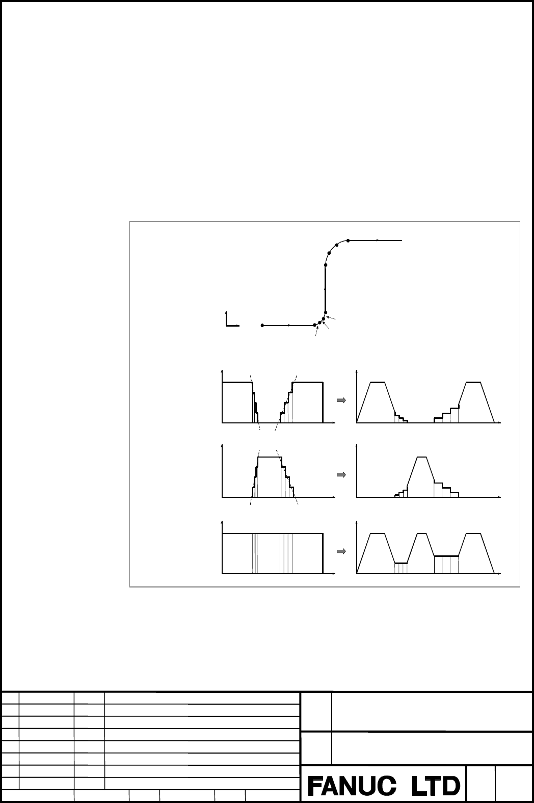
2.17.3 Feedrate determination based on acceleration along each axis
As shown below, when a curve is formed by very short successive line segments, there is no
significant feedrate difference along each axis at each corner. Consequently, the tool need not
be decelerated to compensate for feedrate differences. When taken as a whole, however,
successive feedrate differences generate a large acceleration along each axis.
In this case, the tool must be decelerated to minimize the stress and strain imposed on the
machine, as well as the machining error that may result from such excessive acceleration.
The decelerating speed is a feedrate by which the acceleration of each axis of all axes
becomes below a permissible acceleration which is set by parameter No.8470..
The deceleration speed is determined at each corner. The deceleration speed is calculated
respectively of the starting point and the end point of the block, and the speed in the small
becomes an actual feedrate.
•
••
•
Example
In the example shown below, the tool is accelerated too quickly from N2 to N4 and from N6
to N8 (as indicated by the dashed–line inclinations in the feedrate graphs) when automatic
feedrate control is not used. So, the tool is decelerated.
Fig. 2.17.3 (a) Example of feedrate determination based on acceleration
Feedrate along
the X–axis
N1
N2
Y
X
N3
N4
N6
N7
N8
Feedrate along
the Y–axis
Feedrate along
the tangent to
the path
N1 N5 N9
N1 N5 N9
N9
N5
Contents Summary of FS 16i/18i TA/TB, High-precision Contour Control function for Complex Lathe Additional Manual
- Page 1TECHNICAL REPORT (MANUAL) No.TMN 01/169E Date : Nov. 07, 2001 General Manager of Software Development Center FANUC Series 16i/18i-TA/TB High–precision Contour Control function for Complex Lathe 1. Communicate this report to: Your information only ○ GE Fanuc-N, GE Fanuc-E FANUC Robotics MILACRON ○ Ma
- Page 2FANUC Series 16i /18i –TA/TB Specifications of High–precision Contour Control function for Complex Lathe FANUC Series 16i /18i -TA/TB Title Specifications of High-Precision Contour Control forComplex Lathe Draw No. A-78395E 02 2001.10.04 Description of Cs axis and rotary axis are added. Edit Date De
- Page 3Contents 1 Outline................................................................................................................................ 3 2 Operation ........................................................................................................................... 4 3 Parameter .
- Page 41 Outline 1.1 Outline The milling machining can be done with the compound lathe in high accuracy by using this function. The following functions can be used in the high-precision contour control mode. (1) Function for multiple–block look–ahead acceleration/deceleration before interpolation. This fun
- Page 52 Operation 2.1 Format The high-precision contour control mode can be turned on or off by following instructions. The character of "HPCC" is blinking displayed under the right of the screen in the high- precision contour control mode. G05 P10000 : Start high-precision contour control mode G05 P0 : E
- Page 62.4 G code system G code system in the HPCC mode becomes G code system of the machining centre system. To distinguish from other G codes, the G code of the group which cannot instruct excluding the HPCC mode is displayed in reverse video as shown in the figure below. Reverse display 2.5 Absolute and
- Page 7When the G code system is B or C, absolute or incremental of the instruction value follows G90/G91 which is commanded most later, regardless of off and on of HPCC mode. Example) N1 G00 G90 X100. Z100. ; Absolute N2 G94 non-HPCC N3 G05 P10000 ; N4 G91 G01 X50. Z50. F1000 ; Incremental HPCC N5 G05 P0
- Page 82.7 Positioning and auxiliary functions • Type of positioning The type of positioning instruction (G00) in the HPCC mode is selected according to the undermentioned parameter. No.8403 #1(MSU),#7(SG0) No.8404 #0(STG) Parameter setting 8403#1 8403#7 8404#0 Explanatiom (MSU) (SG0) (STG) - 0 0 0 Alarm i
- Page 92.8 Feed per rotation Feed per rotation Can not be used in HPCC mode. 2.9 Tool position offset Tool position offset (T code) con not be commaned in HPCC mode. The P/S5000 alarm is generated when commanded. The tool position offset should be made effective before the HPCC mode is turned on. 2.10 Cutt
- Page 10• Instruction form When G05 P10000 and G05 P0, and G41/G42 and G40 are to be specified together, G41/G42 to G40 must be nested between G05 P10000 and G05 P0. This means that HPCC mode cannot be started or canceled in cutter compensation (G41/G42) mode. If such a specification is made, the P/S alarm
- Page 11• Cancel When a block containing no movement operation is specified together with the cutter compensation cancel code (G40), a vector with a length equal to the offset value is created in a direction perpendicular to the movement direction of the previous block. Cutter compensation mode is canceled
- Page 122.12 Smooth interpolation 2.12.1 Outline Either of two types of machining can be selected, depending on the program command. (1) For those portions where the accuracy of the figure is critical, such as at corners, machining is performed exactly as specified by the program command. (2) For those port
- Page 13Table 2.12.3 (a) Profile Portions having mainly Portions having mainly a small radius of a large radius of curvature curvature Example of machined Automobile parts Decorative parts, such parts as body side moldings Length of line segment Short Long Resulting surfaces Smooth surface even Uneven surfa
- Page 14Smooth interpolation Interpolated by smooth curve N17 N16 N13 N12 N15 N14 N11 N10 N1 N2 N5 N6 N3 N4 N7 N8 N9 Interpolated by smooth curve Linear interpolation Linear interpolation N17 N16 N13 N12 N15 N14 N11 N1 N10 N2 N5 N6 N3 N4 N7 N8 N9 Fig. 1.3.3 (c) Smooth Interpolation and Linear Interpolation
- Page 152.12.4 Limitations • Controlled axes Smooth interpolation can be specified only for the X–, Y–, and Z–axes and any axes parallel to these axes (up to three axes at one time). • Back-and-forth path machining When back-and-forth path machining is performed for a path that includes inflection points, t
- Page 162.12.5 Example Sample program of smooth interpolation G05 P10000 G05. 1 Q2 X0 Y0 Z0 N01 G91 G01 X1000 Z-300 F500 N02 X1000 Z-200 N03 X1000 Z-50 N04 X1000 Z50 N05 X1000 Z50 N06 X1000 Z-25 N07 X1000 Z-175 N08 X1000 Z-350 N09 Y1000 N10 X-1000 Z350 N11 X-1000 Z175 N12 X-1000 Z25 N13 X-1000 Z-50 N14 X-10
- Page 172.13 NURBS interpolation 2.13.1 Outline This function enables NURBS(non–uniform rational B–spline) curve expression to be directly specified to the CNC. This eliminates the need for approximating the NURBS curve with minute line segments. This offers the following advantages: 1. No error due to appr
- Page 182.13.2 Format G05 P10000 ; : Starting of HPCC mode G06.2 [P_] K_ X_ Y_ Z_ [R_] [F_] ; : Starting of NURBS interpolation mode K_ X_ Y_ Z_ [R_] ; K_ X_ Y_ Z_ [R_] ; K_ X_ Y_ Z_ [R_] ; ... K_ X_ Y_ Z_ [R_] ; K_ ; ... K_ ; G01 ... ; : Ending of NURBS interpolation mode G05 P0 ; : Ending of HPCC mode Eac
- Page 19• Knot The number of specified knots must equal the number of control points plus the rank value. In the blocks specifying the first to last control points, each control point and a knot are specified in an identical block. After these blocks, as many blocks (including only a knot) as the rank value
- Page 202.13.5 NURBS curve Using these variables: k : Rank Pi : Control point wi : Weight x i : Knot ( x i ≤ x i +1 ) Knot vect or [ x 0 , x 1 ,..., x m ] (m = n + k ) t : Spline parameter, The spline basis function N can be expressed with the de Boor–Cox recursive formula, as indicated below: 1 (x i ≤ t
- Page 212.14 Scaling, Coordinate system rotation, Programmable mirror image 2.14.1 Scaling (1) All axis scaling • Outline A programmed figure can be magnified or reduced (scaling). Please set “1” in parameter No.8485#0(G51) and No.5401#0(SCLx) to make this function effective. This function can use only in t
- Page 22(2) Each axis scaling • Outline Each axis can be scaled by different magnifications. Please set “1” in parameter No.8485#0(G51) , No.5401#0(SCLx), and No.5400#6(XSC) to make this function effective. This function can use only in the HPCC mode. This function is an option.(Included in option of scalin
- Page 23(3) Notes concerning scaling and each axis scaling • Instruction form Specify G51 in a separate block. Please cancel with G50 when scaling becomes unnecessary. • Position display The position display represents the coordinate value after scaling. • Magnification (1) If a parameter setting value is e
- Page 24• Invalid scaling This scaling is not applicable to cutter compensation values, tool length offset values, and tool offset values. 1/2 scaling • Coordinate system rotation When both scaling and coordinate system rotation are specified, the coordinate system is rotated after scaling is applied. In th
- Page 25• Other notes Please refer to notes in clause 2.14.4. FANUC Series 16i /18i -TA/TB Title Specifications of High-Precision Contour Control forComplex Lathe Draw No. A-78395E 02 2001.10.04 Description of Cs axis and rotary axis are added. Edit Date Design Description Sheet 24/75 Date 2001.02.14 Desig.
- Page 262.14.2 Coordinate system rotation • Outline It is possible to instruct in the coordinate system rotation in the HPCC mode. Only the coordinate system rotation in the HPCC mode is explained in the following descriptions. Please set “1” in parameter No.8485#0(G51) to make this function effective. This
- Page 27• Plane The coordinate system rotation is executed on selected plane (G17,G18,G19) when G68 is instructed. The G code for selecting a plane (G17,G18,or G19) can be specified before the block containing the G code for coordinate system rotation (G68). • Cutter compensation C Cutter compensation opera
- Page 28• Relationship with other functions Cutter compensation C It is possible to specify G68 and G69 in cutter compensation mode. The rotation plane must coincide with the plane of cutter compensation. Example) N01 G01 G90 X0 Y0 ; N02 G42 X1000 Y1000 F1000 D01 ; N03 G68 R-30000 ; N04 G91 X2000 ; N05 G03
- Page 29Y When only coordinate system rotation is applied When scaling and coordinate system rotation are applied When only scaling is applied Cutting program O X FANUC Series 16i /18i -TA/TB Title Specifications of High-Precision Contour Control forComplex Lathe Draw No. A-78395E 02 2001.10.04 Description
- Page 302.14.3 Programmable mirror image • Outline By a programmed command, the mirror image function can be used for each axis. If the programmable mirror image function is specified when the command for producing a mirror image is also selected by a CNC external switch or CNC setting, the programmable mir
- Page 31(Example of an incorrect program (2)) G51.1…; G68…; …… G50.1…; G69 ; (Example of a correct program) G51.1…; G68…; …… G69 ; G50.1…; Other notes Please refer to notes in clause 2.14.4. • Example If the contour of workpiece to be machined is symmetrical about an axis, use the programmable mirror image
- Page 322.14.4 Notes concerning scaling, coordinate system rotation and programmable mirror image • Modal (1) Please instruct in starting of HPCC (G05 P10000) in the state of G50(scaling cancel), G69.1(coordinate system rotation .cancel), and G50.1(programmabel mirror image cancel). When the HPCC is started
- Page 332.15 Relation between high-precision contour control and another functions • Function which cannot be used with HPCC The following funtions can not be used in HPCC mode. • Sequence Number Comparison and Stop It is not possible to stop by the sequence number in the HPCC mode. • Manual handle retrace
- Page 34• Automatic corner override -G62 • Cutting mode -G64 • Macro call -G65,G66,G67,G66.1 (The subprogram call is possible.) • Three dimensional coordinate conversion -G68.1/G69.1 • Multiple repetitive cycle* -G70∼G76[G72∼G78] • Canned grinding cycle* -G71∼G74[G72∼G78] • Canned cycle for drilling* -G80∼G
- Page 352.16 Look–ahead acceleration/deceleration before interpolation 2.16.1 Acceleration/deceleration type There are three types of acc/decelerations as follows. The bell type is smoother than linear type. (1) Linear acc/deceleration before interpolation (2) Bell-shaped acc/deceleration before interpolati
- Page 362.16.3 Look–ahead bell–shaped acc/deceleration before interpolation (acceleration variable ratio constant type) To use this function, set bit 7 (BDO) and bit 1 (NBL) of parameter No. 8402 to 1, and also set the following parameters: Parameter No. 8400: Parameter 1 for setting the acceleration used f
- Page 37(2) When maximum acceleration is not reached A c c e le r a tio n + T im e − F e e d ra te T im e (1) Acceleration The tool is accelerated to a specified feedrate, starting at the beginning of a block. The tool can be accelerated over multiple blocks. Feedrate Feedrate control by look–ahead bell–sha
- Page 38• Feedrate clamping based on the total travel of the tool in look–ahead blocks When the distance required to decelerate the tool from a specified feedrate is less than the total travel of the tool in the blocks read in advance, the feedrate is automatically clamped to a feedrate from which the tool
- Page 39(2) At the end of acceleration Feedrate Feedrate control by look–ahead bell–shaped acceleration/ dec- eleration before interpolation Specified feedrate Clamp feedrate Total travel of the tool in the blocks read in advance at the end of acceleration Time • Feedrate command and feedrate If an F comman
- Page 40• When the feed hold function is used during acceleration When the feed hold function is used during acceleration, control is performed as described below. (1) While applying constant or increasing acceleration Starting at the point where the feed hold function is specified, the acceleration is grad
- Page 41• Feedrate command and deceleration If an F command is changed by, for example, another F command, the corner deceleration function, or the automatic feedrate determination function, look–ahead bell–shaped acceleration/deceleration before interpolation treats the changed feedrate as a new target fee
- Page 42(3) Single block When the single block function is specified while look–ahead bell–shaped acceleration/deceleration before interpolation is used, control is performed as described below. • While the tool is being accelerated or decelerated when the single block function is specified (a) A + B ≤ Rema
- Page 43• While the tool is not being accelerated or decelerated when the single block function is specified (a) A + B ≤ Remaining travel for the tool in the block being executed when the single block function is specified The tool is gradually decelerated so that the feedrate is 0 upon completion of the ex
- Page 44• How the tool is stopped when decelerated over multiple blocks The tool is decelerated (or accelerated) over multiple blocks until the feedrate becomes 0. Feedrate Single block function specified Time CAUTION 1 Depending on the stop point and remaining blocks, two or more acceleration/deceleration
- Page 45(5) Caution CAUTION 1 When the specification of the dry run function or feedrate override function is changed, the acceleration/deceleration curve must be recalculated while the tool is actually moving along an axis. For this reason, there will be a slight delay before a feedrate change is actually
- Page 462.16.4 Look–ahead bell–shaped acc/deceleration before interpolation (acceleration variable time constant type) To use this function, please set “1” in parameter No.1603#3(SBL) in addition to setting the bell-shaped acc/deceleration of acceleration valiable ratio constant type. • Difference with acce
- Page 47When the pre-reading block becomes insufficient In an acceleration variable ratio constant type, the deceleration is done until the speed becomes 0 once when the pre-reading block becomes insufficient. On the other hand, when the pre-reading block becomes insufficient, the deceleration is done, howe
- Page 482.17 Automatic feedrate control function 2.17.1 Outline This function reads several tens of blocks ahead to exercise automatic feedrate control in HPCC mode. A feedrate is determined on the basis of the conditions listed below. If a specified feedrate exceeds a calculated feedrate, acceleration/dece
- Page 49• Feedrate control conditions In automatic feedrate control mode, the feedrate for the tool is controlled as described below. (a) The feedrate required at a corner is calculated from the specified feedrate difference at the corner along each axis, the tool being decelerated to the calculated feedrat
- Page 502.17.2 Feedrate determination based on a feedrate difference along each axis The speed is decelerated in the corner so that the speed change of each axis should not exceed a permissible speed difference. The permissible speed difference is set by parameter No.8410. • Example Suppose that the specifi
- Page 512.17.3 Feedrate determination based on acceleration along each axis As shown below, when a curve is formed by very short successive line segments, there is no significant feedrate difference along each axis at each corner. Consequently, the tool need not be decelerated to compensate for feedrate dif
- Page 522.17.4 Feedrate determination based on an allowable acceleration during circular interpolation When a block specifies circular feed per minute and bit 3 (CIR) of parameter No. 8475 is set to 1, the feedrate of the tool is automatically determined so that the acceleration along each axis does not exc
- Page 53No override parameter is provided for area 1; the override value for area 1 is always 100%. A feedrate determined with a separate feedrate control function is multiplied by the override value specified for the area to which the angle θ of downward movement belongs. Area 1: 0˚ ≤ θ < 30˚ Area 2: 30˚ ≤
- Page 542.17.6 Ignoring F code commands In a block for which the automatic feedrate control function is enabled, the ignoring of all feed commands (F commands) can be specified by setting bit 7 (NOF) of parameter No. 8451. The feed commands are: (1) Modal F command specified before a block for which the aut
- Page 553 Parameter 3.1 Parameters of look–ahead acceleration and deceleration before interpolation #7 #6 #5 #4 #3 #2 #1 #0 8402 BDO DST BLK NBL [Data type] Bit BDO,NBL Set the type of acceleration/deceleration before interpolation. BDO NBL Meaning 0 0 Acceleration/deceleration prior to interpolation is of
- Page 563.1.2 Bell-shaped acceleration and deceleration before interpolation 8400 Parameter 1 for determining a linear acc/deceleration before interpolation [Data type] Two-word [Unit of data, Valid data range] Valid data range Increment system Unit of data IS-B IS-C Millimeter machine 1 mm/min 10—60000 1--
- Page 578416 The time required to the maximum acceleration in advanced preview bell–shaped acc/deceleration before interpolation [Data type] Two-word [Unit of data] 1ms [Valid data range] 0 to 99999999 (When a parameter No.1603#3(SBL) is set to “0”) or 0 to 400 (When a parameter No.1603#3(SBL) is set to “1”
- Page 58● When an acceleration variable time constant type is selected. (parameter No.1603#3=1) The “tb” of the figure below is set in this parameter. It becomes a linear acc/deceleration before interpolation when “0” is set. Speed Linear acc/deceleration Bell-shaped acc/deceleration ta Depends on a acceler
- Page 593.2 Automatic feedrate control function 8410 Allowable velocity difference in velocity determination considering the velocity difference at corners [Data type] Word axis [Unit of data, Valid data range] Valid data range Increment system Unit of data IS-B IS-C Millimeter machine 1 mm/min 10—60000 1--
- Page 608456 Area–2 override [Data type] Word [Unit of data] % [Valid data range] 0 to 100 (Standard setting: 80) This parameter specifies an override in area 2 of velocity calculation considering the cutting load. 8457 Area–3 override [Data type] Word [Unit of data] % [Valid data range] 0 to 100 (Standard
- Page 618464 Initial feedrate for automatic feedrate control [Data type] Two-word [Unit of data, Valid data range] Valid data range Increment system Unit of data IS-B IS-C Millimeter machine 1 mm/min 10—240000 1—100000 Inch machine 0.1 inch/min 10—96000 1—48000 Rotation axis 1 deg/min 10—240000 1—100000 Thi
- Page 62Speed Max. cutting feedrate Allowable acceleration (parameter No.1432, 1430, or 1422) Time Parameter No.8470 #7 #6 #5 #4 #3 #2 #1 #0 8475 CIR BIP [Data type] Bit CIR The function of automatic feedrate control considering acceleration and deceleration during circular interpolation is: 0: Not used. 1:
- Page 633.4 Acceleration/deceleration after interpolation #7 #6 #5 #4 #3 #2 #1 #0 1602 LS2 [Data type] Bit LS2 Acceleration/deceleration after interpolation for cutting feed in the high precision contour control mode (HPCC mode) is: 0: Not used. (Exponential acceleration/deceleration) 1: Used. (The function
- Page 643.6 Smooth interpolation #7 #6 #5 #4 #3 #2 #1 #0 8485 CDS [Data type] Bit ICK In HPCC mode, smooth interpolation is: 0: Disabled 1: Enabled 8486 Maximum travel distance of a block where smooth interpolation is applied [Data type] Two-word [Unit of data] Increment IS-B IS-C Unit of system data mm inp
- Page 658491 Maximum tolerance of a block where smooth interpolation is applied [Data type] Word [Unit of data] Increment IS-B IS-C Unit of system data mm input 0.001 0.0001 mm inch input 0.0001 0.00001 inch [Valid data range] 0 to 32767 This parameter specifies a tolerance used as a reference to decide whe
- Page 663.7 Scaling and coordinate system rotation #7 #6 #5 #4 #3 #2 #1 #0 8485 G51 [Data type] Bit G51 In high–precision contour control (HPCC) mode, scaling/coordinate system rotation is: 0: Disabled. 1: Enabled. #7 #6 #5 #4 #3 #2 #1 #0 5400 SCR XSC RIN [Data type] Bit RIN Coordinate rotation angle comman
- Page 675411 Magnification used when scaling magnification is not specified [Data type] Two-word [Unit of data] 0.001 or 0.00001 times (Selected using SCR, #7 of parameter No.5400) [Valid data range] 1 to 999999 This parameter sets the scaling magnification. This setting value is used when a scaling magnifi
- Page 68#7 #6 #5 #4 #3 #2 #1 #0 8485 G02 [Data type] Bit G02 In HPCC mode, helical interpolation is: 0: Disabled. 1: Enabled. #7 #6 #5 #4 #3 #2 #1 #0 8414 RRD [Data type] Bit RRD In the axis of the diameter programming, the program instruction in the HPCC mode is: 0: Radius programming 1: Diameter programmi
- Page 694 Signal HPCC mode signal MHPCC (F066#6) [Classification] Output signal [Function] Indicates that the system is set to high–precision contour control mode (HPCC mode). [Output condition] The signal is set to 1 if G05 P10000 (HPCC mode ON) is specified in a program. The signal is set to 0 if G05 P0 i
- Page 705 Alarm and message Number Message Description 10 IMPROPER G–CODE · There is no option of the corresponding function. · An unusable G code G is specified. · The following instructions are commanded in G00 mode. G50 / G51 (Scaling) G68 / G69 (Coordinate system rotation) G50.1 / G51.1 (Programmable mi
- Page 716 Notes 6.1 Notes on operation Interlock (1) The interlock signal for each axis and direction is not effective in HPCC operation. (2) Please set “1” in parameter No.8404#7(EIL) to make each axis interlock signal effective in HPCC operation. Each axis machine lock and mirror image Neither the mirror
- Page 72Positioning or auxiliary function and cutter compensation C When the G00 of Type-A or the auxiliary function is executed in the cutter compensation mode, the offset vector made in the block before of that is held. Exapmle 1 ) When the undermentioned program is executed, the starting point of N6 is d
- Page 736.3 Acceleration/deceleration before interpolation in look–ahead blocks Short blocks If there is a series of very short blocks, for each of which the rate of acceleration/deceleration before interpolation is low, the actual feedrate may not reach the programmed feedrate. 6.4 Automatic feedrate contr
- Page 747 The function table which can be used by a high-precision contour control The function excluding this cannot be used. Item Specifications Remarks Controlled axis Controlled axis 2 axes Controlled path 1 path Simultaneously controlled axes 2 axes Controlled axis expansion(total) Max. 8 axes Simultan
- Page 75Item Specifications Remarks Interpolation function Positioning G00 Linear interpolation G01 Circular interpolation G02,G03 Helical interpolation Circular interpolation plus max. 2 The option of helical interpolation is necessary. axes linear interpolation Smooth interpolation G05.1 Q2 Only in the HP
- Page 76Item Specifications Remarks Auxiliary/Spindle speed function Auxiliary function It is necessary to set “1” in parameter No.8403#1 (MSU). The HPCC mode is automatically canceled once when instructing in the auxiliary function, and buffering is stopped. nd 2 auxiliary function It is necessary to set “