Series 16i Additional Manual Page 45
Additional Manual
45
/
88
A-78710E
Edit
Apprv. Desig.
Sheet
Title
Draw
No.
Date
Design
Descri
p
tion
Date
FANUC Series 16i –MB, 18i –MB5
Tool Radius Compensation For 5-Axis
machining Specifications
Dec.01.2001
02 Mar.22.2002
T.Mochia All revision
H.Kouzai
Sheet
T.Mochida H.Kouzai
03 Mar.28.2003
MTanaka All revision H.kouzai
04 Aug.05.2003
T.Horie Intersection offset, G-code unification add. H.kouzai
05 Jun.02.2004 Intersection offset(tool rotation type, Mixed type)
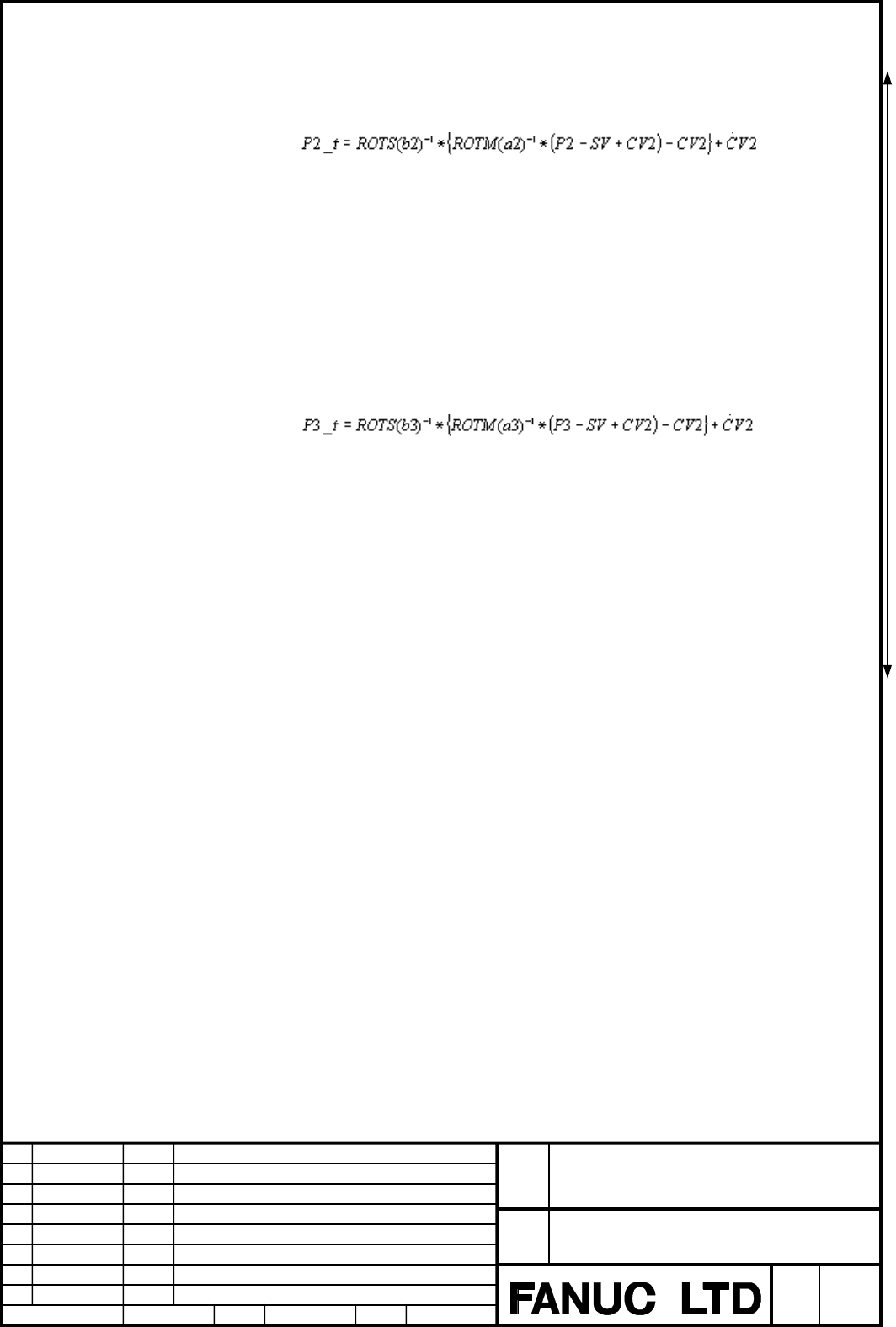
6. Conversion from P2 to P2' used to calculate cutter compensation
(1) P2 on the workpiece coordinate system which is commanded by N2 block is
converted to P2_t on the table coordinate system.
So, SV is the vector given as follows:
(
)
{
}
21)0()0(
11
CVCVWVaROTMbROTSSV −−∗∗−=
−−
(2) P2 on the workpiece coordinate system which is commanded by N2 block is
converted to P2' on the workpiece coordinate system in the state of the N2 block.
(
)
{
}
WVCVCVCVtPbROTSaROTMP −+
+
−
∗
∗
= 122_2)2()2('2
7. Conversion from P3 to P3' used to calculate cutter compensation
(1) P3 on the workpiece coordinate system which is commanded by N3 block is
converted to P3_t on the table coordinate system.
So, the SV is the vector given as follows:
(
)
{
}
21)0()0(
11
CVCVWVaROTMbROTSSV −−∗∗−=
−−
(2) P3 on the workpiece coordinate system which is commanded by N2 block is
converted to P3' on the workpiece coordinate system in the state of the N2 block.
(
)
{
}
WVCVCVCVtPbROTSaROTMP −+
+
−
∗
∗
= 122_3)2()2('3
8. Calculation of the cutter compensation vector using three points P1', P2', P3'
The calculation is similar to the calculation of cutter compensation C.
4)
Contents Summary of Series 16i Additional Manual
- Page 1FANUC Series 16i-MB FANUC Series 18i-MB5 Tool Radius Compensation For 5-Axis Machining Specifications FANUC Series 16i –MB, 18i –MB5 Title Tool Radius Compensation For 5-Axis machining Specifications 05 Jun.02.2004 Intersection offset(tool rotation type, Mixed type) Draw 04 Aug.05.2003 T.Horie Inter
- Page 2- Contents - 1 GENERAL.........................................................................................................................................................3 2 TOOL RADIUS COMPENSATION FOR TOOL ROTATION TYPE MACHINE ...............................................5 2.1 TOOL SIDE OF
- Page 31. General For machines having multiple rotation axes for freely controlling the orientation of a tool axis, this function calculates a tool vector from the positions of these rotation axes. The function then calculates a compensation vector in a plane (compensation plane) perpendicular to the tool
- Page 4<3> Mixed-type machine Z B X C Y Fig.1.1 ・Allowed functions When the tool radius compensation for 5-axis machining is executed, the following functions are allowed: (1) Linear acceleration/deceleration before interpolation or bell-shaped acceleration/deceleration before interpolation (2) Deceleratio
- Page 52. Tool radius compensation for tool rotation type machine General In a 5-axis machine having two tool rotation axes as shown in the figure below, this function can perform cutter compensation. Shown below is a 5-axis machine that has tool rotation axis B on the Y-axis and tool rotation axis C on th
- Page 62.1 Tool Side offset This type of cutter compensation performs cutter compensation in a plane (compensation plane) perpendicular to the tool vector. Programmed tool path Tool vector (before compensation) Cutter compensation vector Tool center path(after compensation) Z Y X Compensation Cutter plane
- Page 7Description ・Operation at compensation start-up and cancellation (1) Type A The tool is moved in the same way as for cutter compensation as shown below. Operation in linear interpolation :Tool center path :Programmed tool path Tool G40 G41.2 Operation in circular interpolation :Tool center path :Pro
- Page 8Operation in circular interpolation :Tool center path :Programmed tool path G40 G42.2 Tool Fig.2.4 Operation at compensation start-up and cancellation (Type B) (3) Movement perpendicular to the next movement When G41.2, G42.2, or G40 is specified, a block that moves the tool linearly by the amount o
- Page 9NOTE When the movement direction is perpendicular to the next movement (bit 1 (SUV) of parameter No. 5003 is set to 1), the following conditions must always be satisfied at startup and cancellation: 1 A block specifying G40, G41.2, or G42.2 must be in the G00 or G01 mode. 2 A block specifying G40, G
- Page 10・Operation during compensation Operations such as change of the offset direction and offset value, retention of a vector, and interference checks are performed in the same way as for cutter compensation. However, G39 (corner rounding) cannot be specified. So, note the following: (1) When the tool ce
- Page 11(2) When the tool moves at a corner, the feedrate of the previous block is used if the corner is positioned before a single-block stop point; if the corner is after a single-block stop point, the feedrate of the next block is used. F100 Q1' Q2' (Single block stop point) : Tool center path Q : Progra
- Page 12・Compensation vector calculation Q e1=VT VD Z P e2 e3 Y X R Fig.2.10 Compensation vector calculation In above figure, cutter compensation vector VD at point Q is calculated as follows : (1) Calculating the tool vector (VT) (2) Calculating the coordinate conversion matrix (M) Coordinate systems are d
- Page 13(3) Converting coordinates from coordinate system C1 to coordinate system C2 The coordinates of the start and end points P and Q of a block and coordinates of the end point R of the next block in coordinate system C1 are converted to coordinates P', Q', and R' in coordinate system C2, respectively,
- Page 14・Calculation used when the compensation plane is changed (1) When a rotary axis and linear axis are specified at the same time When a rotary axis and linear axis are specified in the same block in the G41.2 or G42.2 mode (the compensation plane changes frequently), the cutter compensation vector is
- Page 15Vector calculation at the end point (Q) of block N2 - The tool vector (VT) and coordinate conversion matrix (MN2) are calculated using the coordinates (B = 0, C = 0) of the rotary axis at point Q. - The cutter compensation vector (VN2) is calculated using the resultant coordinates into which three p
- Page 16Z Y N3 X N10 N7 N4 N6 N8 N9 N5 Fig.2.14 Conceptual Diagram Z C A Vb Va 45° 46° B Y Va: Tool direction vector when A = -46 Vb: Tool direction vector when A=45 A: End point of N3 B: End point of N4 C: End point of N6 Fig.2.15 Tool Direction Vector e3 e2 V2 B’ C’ A’ V1 A’ : Point A projected onto the c
- Page 17The move direction of A'B' is opposite to that of B'C', so that two compensation vectors, V1 and V2, are produced at point B' (end point of N4). In such case, there is a possibility of overcutting, so an alarm (PS41) is issued at N4. (1) Conditions for issuing the interference alarm Suppose that a m
- Page 18e3 e2 B’ C’ A’ Ra Rb A’ : Point A projected onto the compensation plane B’ : Point B projected onto the compensation plane C’ : Point C projected onto the compensation plane Ra: Vector A'B' Rb: Vector B'C' Fig.2.18 Programmed path before and after the end point (point B) of N4 (in the compensation p
- Page 19Fig.2.19 Q1 Command A perpendicular vector can also be generated by specifying G41.2 or G42.1 in the next block as follows: Example: N6 G41.2 Y-400 Z0 (2) Q2 command With a program specifying a linear-to-linear connection, up to two compensation vectors are generated. In this case, the second vector
- Page 20・Others When the tool movement changes linear to circular (helical), circular (helical) to linear, or circular (helical) to circular (helical), the start, end, and center points of a circular (helical) movement are projected on the compensation plane that is perpendicular to the tool axis, and a com
- Page 212.2 Leading Edge Offset Leading edge offset is a type of cutter compensation used when a workpiece is machined with the edge of a tool. The tool is automatically shifted by the amount of cutter compensation on the line where a plane formed by a tool vector and tool movement direction meets a plane p
- Page 22Description ・Operation at startup and cancellation The operation performed at leading edge offset startup and cancellation does not vary. When G41.3 is specified, the tool is moved by the amount of compensation (Vc) in the plane formed by the movement vector (VM) of the block after the G41.3 block a
- Page 23・Operation during compensation The tool center moves so that a compensation vector (VC) perpendicular to the tool vector (VT) is created in the plane formed by the tool vector (VT) at the end point of each block and the movement vector (VM) of the next block. Tool center path (after compensation) VT
- Page 24・Block immediately before the offset cancel command (G40) In the block immediately before the offset cancel command (G40), a compensation vector is created from the movement vector of that block and the tool vector at the end point of the block as shown below : Tool center path (after compensation)
- Page 25(2) (VMn+1,VTn) < 0 (90deg < θ < 180deg.) VCn θ Direction of VCn VTn -(VMn+1 × VTn)× VTn VMn+1 VMn+1 VTn θ VCn Fig.2.30 Direction of the compensation vector (2) The compensation vector (VCn) of block n is calculated from VTn and VMn+1 as described below. R = Offset R= offset value value VTX VTn =
- Page 26・Compensation performed when θ is approximately 0°, 90°, or 180° When the included angle θ between VMn+1 and VTn is regarded as 0°, 180°, or 90°, the compensation vector is created in a different way. So, when creating a program, note the following points: (1) Setting a variation range for determini
- Page 27(2) Compensation vector when θ is regarded as 0° or 180° At startup (when G41.3 is specified), alarm P/S 5408 is issued. This means that the tool vector of a block and the movement vector of the next block must not point in the same direction or in opposite directions at startup. At other than start
- Page 282.3 Tool tip position (cutting point) command General For machines having a rotation axis for rotating a tool, this function performs cutter compensation for 5-axis machining at the tool tip position if a programmed point is specified with a pivot point. When this function is used, the programmed po
- Page 293D cutter compensation vector according to this specification Program-specified point (pivot point) Conventional 3D cutter compensation vector Vector from program-specified point (pivot point) to tool tip position (cutting point) Distance from program-specified Tool center point (pivot point) to cut
- Page 30(2) Calculate the cutter compensation vector VD from the tool tip positions (cutting points) PT, QT, and RT and the tool gradient VT. (3) Add cutter vector VD to programmed point (pivot point) Q and set the result as the end point position. LC e3 Tool tip position R’ VT e1 Tool radius VD VD’ P’ e2 e
- Page 312.4 Specification of parameters ・Relationships between rotary axes and rotary planes [19610 to 19619] These parameters set the relationships between rotary axes and rotary planes. In general, the direction vector of a rotary axis has components in three directions. This function, however, can perfor
- Page 32Up to two sets of such parameter settings can be specified. Thus, it is possible to compensate a slant rotary head controlled with two rotary axes. For the calculation of the compensation amount, calculation is performed on the first rotary axis, and then calculation is performed on the second rotar
- Page 33・Parameter example When specifying the parameters related to a machine configuration, see the table below. For the machine shown in Fig.2.1, set the parameters according to the following table. Axis numbers is supposed to be as follows: X = 1, Y = 2, Z = 3, B = 4, and C = 5 Parameter Setting Descrip
- Page 345) 3. Intersection offset for tool rotation type machine General When parameter No.19607#4 is set to 1, tool radius compensation for 5 axis machining can be applied to the tool rotation type machine whose two rotary axes don't intersected. ・Parameter example In the machine explained in this example,
- Page 35Parameter Setting Description 5) No. value (IS-B) 19607#4 1 Intersection offset for tool rotation type machine is used 19680 2 Mechanical unit type 19681 6 (C) Controlled-axis number for the first rotation axis 19682 3 (Z) Axis direction of the first rotation axis 19683 0 Inclination angle when the
- Page 364. Tool radius compensation for rotary table type machine General Cutter compensation can be performed for a 5-axis machine having a rotary table as shown in the figure below. Shown below is a 5-axis machine that has table rotation axis A on the X-axis and table rotation axis B on the Y-axis. This m
- Page 374.1 Tool side offset Format ・Startup G41.4 (or G42.4) IP_ D_ ; G41.4 : Cutter compensation, left (group 07) G42.4 : Cutter compensation, right (group 07) IP_ : Value specified for moving an axis D_ : Code specifying the cutter compensation amount (1 to 3 digits) ・Canceling the tool side offset G40 I
- Page 384.2 Description ・Cutter compensation The tool radius compensation for rotary table type machine basically performs operations in conformance with cutter compensation. The operations different from those of cutter compensation are described below. For a description of the specifications and cautions
- Page 39(2) Definitions P1 = ( x1 , y1 , z1 ) , P2 = ( x2 , y 2 , z 2 ) , P3 = ( x3 , y 3 , z3 ) P0 : Origin of the table coordinate system (parameter No.19734) (3) Calculation of the matrix for conversion from the workpiece coordinate system to the table coordinate system Reference angle conversion matrix
- Page 40・Parameter example On the machine shown in Fig.4.1 parameters must be specified as follows: The axis numbers are assumed as follows: X = 1, Y = 2, Z = 3, A = 4, B = 5 Parameter Setting Description No. (IS-B) 19720 1 (X) Axis number of linear axis 1 19721 2 (Y) Axis number of linear axis 2 19722 3 (Z
- Page 415. Intersection offset for rotary table type machine 4) General When parameter No.19607#4 is set to 1, tool radius compensation for 5 axis machining can be applied to the rotary table type machine whose two rotary axes don't intersected.(See.Fig5.1) Y Z Table coordinate A system B X Y shows the dire
- Page 424) Also tool radius compensation for 5 axis machining can be applied to the rotary table type machine whose rotary axes are inclined to a X-Y plane, a Y-Z plane or a Z-X plane of the machine coordinate system.(See.Fig4.2) Such rotary axis is called inclined rotary axis here after. The machine of the
- Page 434) ・ Formulas (1) Machine with rotary axes which don't intersect With the machine of the Fig.5.1, the cutter compensation vector at end point N2 in the following example program is calculated as follows: Refer to the after-mentioned parameter setup example for the setting parameter of the machine of
- Page 444) 3. Definitions of the table coordinate system The origin is assumed to be the point on the first rotary table axis (master). The direction of each basic axis is supposed to correspond to the workpiece coordinate system when the agnle of both rotary table axes is 0 degree. The table coordinate sys
- Page 456. Conversion from P2 to P2' used to calculate cutter compensation 4) (1) P2 on the workpiece coordinate system which is commanded by N2 block is converted to P2_t on the table coordinate system. So, SV is the vector given as follows: { SV = − ROTS (b0) −1 ∗ ROTM (a0)−1 ∗ (WV − CV 1) − CV 2 } (2) P2
- Page 46(2) Machine with inclined rotary axis 4) In the case of the inclined rotary axis control mode, the conversion matrix is changed as follows: The machine compositio of the Fig.5.2 is taken as an example. The conversion matrix (master conversion matrix) of the rotary direction CW on the axis which is i
- Page 474) ・ Parameter example (1) Machine with rotary axes which don't intersect In the machine explained in this example, the first, second, third, fourth, fifth, and sixth axes are, respectively, X, Y, Z, A, B, and C. This is an example of setting parameters for the table rotation type machine shown belo
- Page 484) Parameter Setting Description No. value (IS-B) 19607#4 1 Intersection offset for rotary table type machine is used 19720 1 (X) Axis number of linear axis 1 (first axis of the workpiece coordinate system) 19721 2 (Y) Axis number of linear axis 2 (second axis of the workpiece coordinate system) 197
- Page 494) (2) Machine with inclined rotary axis In the machine explained in this example, the first, second, third, fourth, fifth, and sixth axes are, respectively, X, Y, Z, A, B, and C. This is an example of setting parameters for the table rotation type machine shown below. Rotary axis B is the table rot
- Page 504) Parameter Setting Description No. value (IS-B) 19607#4 1 Intersection offset for rotary table type machine is used 19720 1 (X) Axis number of linear axis 1 (first axis of the workpiece coordinate system) 19721 2 (Y) Axis number of linear axis 2 (second axis of the workpiece coordinate system) 197
- Page 516. Tool Radius Compensation for Mixed-type machine General This function can perform cutter compensation in a 5-axis machine having a rotary table and a tool axis as shown in the figure below. Shown below is a 5-axis machine that has tool axis A on the X-axis (the tool axis direction is along the Z-
- Page 526.1 Tool side offset ・Startup G41.5 (or G42.5) IP_ D_ ; G41.5 : Cutter compensation, left (group 07) G42.5 : Cutter compensation, right (group 07) IP_ : Specified amount of axial movement D_ : Code specifying the amount of cutter compensation (1 to 3 digits) ・Canceling the tool side offset G40 IP_ ;
- Page 536.2 Description ・Cutter compensation Basically, the operations of the function of Tool radius compensation for 5-axis machining conform to those of three-dimensional cutter compensation. The following explanation mainly covers operations different from those of three-dimensional cutter compensation.
- Page 54NOTE 1. This function cannot be used in the three-dimensional coordinate conversion mode. 2. In addition to the cautions given here, the cautions on Cutter compensation in tool rotation type machine apply to this function. ・Formulas The three-dimensional cutter compensation vector at the N2 end poin
- Page 55The conversion matrix for Q is M 2 −1 = Rc (c2 )−1 The conversion matrix for R is M 3−1 = Rc (c3 )−1 cos c sin c 0 where Rc ( c ) = − sin c cos c 0 0 0 1 (2) Calculation of the three points P', Q', and R' used for the calculation of three-dimensional cutter compensation The conversion
- Page 56(2) Creation of the basic vector of coordinate system C2 for applying two-dimensional cutter compensation Let the tool direction vector in the state of the N2 end point be VT . (cos RA )(cos RB ) VT = ROTα ( a2 ) N 0 −1 (cos R )(sin R ) A B − sin RA e2 is defined as follows. Note tha
- Page 57(4) Coordinate system conversion matrix for conversion from coordinate system C1 to coordinate system C2 The coordinate system conversion matrix for conversion from coordinate system C1 to coordinate system C2 is represented by the following formula: e 2 N = e3 e1 On the other hand, th
- Page 58・Parameter example When specifying the parameters related to a machine configuration, see the table below. For the machine shown in Fig.6.1, set the parameters according to the following table. Axis numbers is supposed to be as follows: X = 1, Y = 2, Z = 3, A = 4, and C = 5 Parameter Setting Descrip
- Page 597. Intersection offset for Mixed-type machine 5) General When parameter No.19607#4 is set to 1, tool radius compensation for 5 axis machining can be applied to the mixed type machine whose two rotary axes don't intersected. ・Parameter example In the machine explained in this example, the first, seco
- Page 605) Parameter Setting Description No. value (IS-B) 19607#4 1 Intersection offset for Mixed-type machine is used 19680 21 Mechanical unit type 19681 5 (B) Controlled-axis number for the first rotation axis 19682 2 (Y) Axis direction of the first rotation axis 19683 0 Inclination angle when the first r
- Page 614) 8. G-code unification General G-code number of the tool side offset varies by the machine type ( tool rotation type, rotary table type, and mix-type). When parameter No.19609#0 is set to 1, this is unified into G-code of the tool rotaion type, G41.2 and G42.2. Format ・Tool side offset G41.2 (or G
- Page 629. Restrictions ・Interference check In the Tool radius compensation for 5-axis machining mode, an interference check is performed using a specified position in the workpiece coordinate system and a compensation vector. The interference check avoidance function cannot be used. ・Corner arc (G39) In th
- Page 63- Advanced preview control -G08 (Please use AI High Precision Contour Control) - Polar coordinate interpolation -G12.1, G13.1 - Polar coordinate command -G15, G16 - Reference position return check -G27 - Automatic reference position return check command -G28,G29,G30 - Skip function -G31 - Threading
- Page 64・Unavailable functions In the mode for this function, the following functions cannot be used, The warning message is displayed on the screen when the following functions are used. : ・MDI operation In the mode for this function, the following functions cannot be used, The alarm(P/S5196) is issued whe
- Page 6510. Parameters 10.1 About the machine configuration ・First set and Second set If there are two rotary axes for controlling the orientation of a tool or two rotary axes for controlling the orientation of a table, a typical structure is such that a rotary mechanism is on the tip of another rotary mech
- Page 6619615 Rotary axis used to execute three-dimensional cutter compensation and tool radius compensation for 5-axis machining (second set) 19616 Linear axis 1 used to execute three-dimensional cutter compensation and tool radius compensation for 5-axis machining (second set) 19617 Linear axis 2 used to
- Page 67A) If the components of the direction vector of a rotary axis are in a single direction (type A) This is a case in which the rotary axis rotates about any one of the three basic axes. 1) Set the axis numbers for the rotary axis, linear axis 1, and linear axis 2. 2) Set 0 for both linear axis 3 and t
- Page 6819620 Reference angle of rotary axis used to execute three-dimensional cutter compensation (first set) 19621 Reference angle of rotary axis used to execute three-dimensional cutter compensation (second set) [Data type] 2 Word [Unit of data] increment system IS-B IS-C Unit Data unit 0.001 0.0001 deg
- Page 69If the tool axis is in the direction of linear axis 3 Linear axis 3 RA = 0.0 Linear axis 2 RB = 0.0 Linear axis 1 If the tool axis is in the direction of linear axis 1 Linear axis 3 RA = 0.0 Linear axis 2 RB = 90.0 Linear axis 1 19631 Variation in determining an angle for leading edge offset [Input
- Page 7019632 Distance from the program-specified point (pivot point) to the tool tip position (cutting point) [Data type] 2 Word [Unit of data] increment system IS-B IS-C unit Millimeter machine 0.001 0.0001 mm Inch machine 0.0001 0.00001 inch [Valid data range] -99999999 ~ +99999999 Set the distance from
- Page 7110.3 Parameters related to rotary table axes 19720 Axis number of linear axis 1 in the tool radius compensation for 5-axis machining 19721 Axis number of linear axis 2 in the tool radius compensation for 5-axis machining 19722 Axis number of linear axis 3 in the tool radius compensation for 5-axis m
- Page 72If the rotary direction of the rotary axis is the reverse of what is described in the table above, set a negative value for parameter No.19723 or 19725. If the direction with an agular displacement of 0 differs from what is described in the table above, specify parameters No.19730 and 19731, assumin
- Page 734) 10.4 Parameters related to intersection offset for rotary table type machine - Master and slave When there are two rotation axes for controlling the orientation of a tool or two rotation axes for controlling the orientation of a table, a typical structure is such that a rotation mechanism is on a
- Page 745) #7 #6 #5 #4 #3 #2 #1 #0 19607 RTI [Data type] Bit #4 RTI The intersection offset for tool rotation type ,rotary table type, mixed-type machine of tool radius compensation for 5-axis machining should be 0: invalid. 1: valid. 19666 Tool holder offset value [Data type] 2 Word [Unit of data] incremen
- Page 754) 19680 Type of a mechanical unit [Data type] Byte [Valid data range] 0 ~ 21 Specify the type of a mechanical unit. 5) Mechanical unit Controlled rotation PRM19680 Master and slave type axis Mechanism having no 0 rotation axis The first rotation axis is the master, Tool rotation Two rotation axes o
- Page 764) 19681 Controlled axis number for the first rotary axis [Data type] Byte [Valid data range] 0 ~ number of controlled axes Specify the controlled axis number for the first rotary axis. For a hypothetical axis (when bit 0 (IA1) of parameter No. 19696 is 1), set 0. 19682 Axis direction for the first
- Page 774) 19683 Angular angle when the first rotary axis is a angular axis [Data type] 2 Word [Unit of data] increment system IS-B IS-C Unit Data unit 0.001 0.0001 deg [Valid data range] -99999999 ~ +99999999 When a value 1 to 3 is set in parameter No. 19682, set 0 degrees. When a value 4 to 6 is set in pa
- Page 7819685 Rotation angle when the first rotary axis is a hypothetical axis 4) [Data type] 2 Word [Unit of data] increment system IS-B IS-C Unit Data unit 0.001 0.0001 deg [Valid data range] -99999999 ~ +99999999 When the first rotation axis is a hypothetical axis (bit 0 (IA1) of parameter No. 19696 is 1
- Page 794) 19689 Retraction direction for the second rotary axis [Data type] Byte [Valid data range] 0~1 Set the direction in which the second rotation axis rotates as a mechanical motion when a positive move command is issued. 0: Clockwise direction as viewed from the negative to positive direction of the
- Page 804) 19697 Reference tool axis direction [Data type] Byte [Valid data range] 0~3 Set the tool axis direction in the machine coordinate system when the rotation axes for controlling the tool are all at 0 degrees. Also, set the tool axis direction in the machine coordinate system in a mechanism in which
- Page 814) 19700 Rotary table position (X-axis, one of the basic three axes) 19701 Rotary table position (YX-axis, one of the basic three axes) 19702 Rotary table position (Z-axis, one of the basic three axes) [Data type] 2Word [Unit of data] increment system IS-B IS-C unit Millimeter machine 0.001 0.0001 m
- Page 8219703 Intersection offset vector between the first and second rotary axes of the 4) table (X-axis, one of the basic three axes) 19704 Intersection offset vector between the first and second rotary axes of the table (Y-axis, one of the basic three axes) 19705 Intersection offset vector between the fi
- Page 8319709 Intersection offset vector between the tool axis and tool rotation axis (X-axis 5) of the basic three axes) 19710 Intersection offset vector between the tool axis and tool rotation axis (Y-axis of the basic three axes) 19711 Intersection offset vector between the tool axis and tool rotation ax
- Page 8419712 Intersection offset vector between the second and first rotation axes of the 5) tool (X-axis of the basic three axes) 19713 Intersection offset vector between the second and first rotation axes of the tool (Y-axis of the basic three axes) 19714 Intersection offset vector between the second and
- Page 854) 19720 Axis number of linear axis 1 in the tool radius compensation for 5-axis machining 19721 Axis number of linear axis 2 in the tool radius compensation for 5-axis machining 19722 Axis number of linear axis 3 in the tool radius compensation for 5-axis machining [Data type] Byte [Valid data rang
- Page 8610.5 Parameters related to G-code unification 4) #7 #6 #5 #4 #3 #2 #1 #0 19607 CGR [Data type] Bit #0 CGR In the machine which contains a table rotation axis, when the tool radius compensation for 5-axis machining is done, the commanded G-code 0: Uses G41.4 or G42.4 with the rotary table type machin
- Page 8711. Alarm and message No. Message Description P/S33 CRC:NO INTERSECTION There is not point of intersection of the compensated tool center path during cutter compensation. P/S37 CRC:PLANE CHANGE An attempt was made to change the plane in the cutter compensation mode. To change the plane, cancel the c
- Page 88No. Message Description P/S5409 ILLEGAL PARAMETER IN G41.3 The parameter settings (parameter Nos. 19610 to 19619) for determining the relationship between the axis of rotation and the rotary plane are incorrect. P/S5460 ILLEGAL USE OF G41.4/G42.4 (1) Any of the parameters No.19720 to 19726, related