FANUC I/O Unit-MODEL A Connection And Maintenance Manual Page 36
Connection And Maintenance Manual
B-61813E/03 CONNECTIONS 5. DIGITAL INPUT/OUTPUT MODULES
−27−
5 DIGITAL INPUT/OUTPUT MODULES
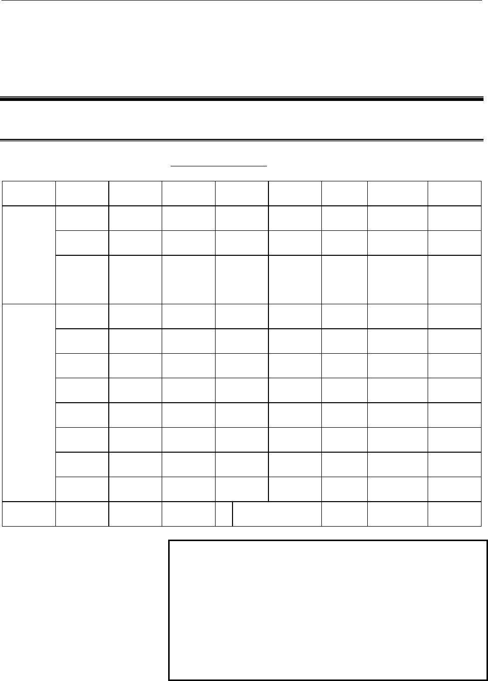
5.1 LIST OF MODULES
Digital input modules
Input type module
name
Rated
voltage
Rated
current
Polarity Response
time
Points External
connection
LED
display
AID32A1 24VDC 7.5 mA Both Maximum
20 ms
32 Connector A not
provided
AID32B1 24VDC 7.5 mA Both Maximum
2 ms
32 Connector A not
provided
Non-
insulation
type DC
input
AID32H1 24VDC 7.5 mA Both Maximum
2 ms
Maximum
20 ms
8
24
Connector A not
provided
AID16C 24VDC 7.5 mA NEG Maximum
20 ms
16 Terminal
block
provided
AID16K 24VDC 7.5 mA NEG Maximum
2 ms
16 Terminal
block
provided
AID16D 24VDC 7.5 mA POS Maximum
20 ms
16 Terminal
block
provided
AID16L 24VDC 7.5 mA POS Maximum
2 ms
16 Terminal
block
provided
AID32E1 24VDC 7.5 mA Both Maximum
20 ms
32 Connector A not
provided
AID32E2 24VDC 7.5 mA Both Maximum
20 ms
32 Connector B not
provided
AID32F1 24VDC 7.5 mA Both Maximum
2 ms
32 Connector A not
provided
Insulation
type DC
input
AID32F2 24VDC 7.5 mA Both Maximum
2 ms
32 Connector B not
provided
AC input AIA16G 100 to
120VAC
10.5 mA
(120VAC)
ON Max 35ms
OFF Max 45ms
16 Terminal
block
provided
NOTE
1Polarity
Negative : 0 V common (current source type) Regard
to be ON when input is at Low level.
Positive : 24 V common (current sink type) Regard to
be ON when input is High level.
2 Connector A : HONDA MR Connector
Connector B : Flat Cable Connector
3 For the details of the specifications for each module,
refer to the section 5.3.
Contents Summary of FANUC I/O Unit-MODEL A Connection And Maintenance Manual
- Page 1
- Page 2B-61813E/03 DEFINITION OF WARNING, CAUTION, AND NOTE DEFINITION OF WARNING, CAUTION, AND NOTE This manual includes safety precautions for protecting the user and preventing damage to the machine. Precautions are classified into Warning and Caution according to their bearing on safety. Also, suppleme
- Page 3
- Page 4B-61813E/03 PREFACE PREFACE This manual describe the following products: Applicable models Name of products Abbreviation FANUC I/O Unit-MODEL A I/O Unit-A FANUC I/O Unit-MODEL B I/O Unit-B Applicable CNCs Name of products Abbreviation FANUC Power Mate-MODEL A Power Mate-A FANUC Power Mate-MODEL B Po
- Page 5
- Page 6B-61813E/03 Contents PREFACE I CONNECTIONS 1. FANUC I/O LINK.............................................................................................................3 1.1 CONFIGURATION................................................................................................................
- Page 7Contents B-61813E/03 8. HIGH SPEED COUNTER MODULE.............................................................................70 8.1 OUTLINE OF HIGH SPEED COUNTER MODULE ..................................................................... 70 8.2 SPECIFICATIONS OF HIGH SPEED COUNTER MODULE..........
- Page 8B-61813E/03 Contents 10.6.5 Maximum transmission distance by optical fiber cable ....................................................................125 11. I/O LINK DUMMY UNIT ............................................................................................126 11.1 OVERVIEW..............
- Page 9
- Page 10I. CONNECTION�
- Page 11
- Page 12B-61813E/03 CONNECTIONS 1. FANUC I/O LINK 1 FANUC I/O Link I/O Link is a serial interface with a purpose to transfer I/O signals (bit data) betweenCNC, cell controller, the I/O Unit-A, the Power Mate-A, etc. at high speed. −3−
- Page 131. FANUC I/O LINK CONNECTIONS B-61813E/03 1.1 CONFIGURATION 1) The FANUC I/O Link is made up of one master and a number of slaves. Master : Series 0-C, Series 15/16/18/20/21, Series 15i/16i/18i/20i/21i, Power Mate-D/H, Power Mate i- D/H, F-D Mate Slave : I/O Unit-A, Power Mate operator's panel conne
- Page 14B-61813E/03 CONNECTIONS 1. FANUC I/O LINK 1.2 ALLOCATION OF I/O POINTS I/O Link has 1024 input points and 1024 output points as viewed from the master. I/O data is periodically transferred between the master and slaves by allotting these I/O points to each slave. Each slave occupies specified number
- Page 151. FANUC I/O LINK CONNECTIONS B-61813E/03 1) Sum the numbers of the occupied I/O points in Table 1 for all slaves connected with a single I/O Link. The sum must satisfy the following restriction : Number of input points ≦ 1024 (per one I/O Link) Number of output points ≦ 1024 (per one I/O Link) 2) N
- Page 16B-61813E/03 CONNECTIONS 1. FANUC I/O LINK In this case, as the number of input points is not larger than that of the output points, the number of input points is assumed to be equal to that of the output points, in other words, 256 points. −7−
- Page 172. I/O UNIT CONFIGURATION CONNECTIONS B-61813E/03 2 I/O UNIT CONFIGURATION 5-slot horizontal base unit (ABU05A) 10-slot horizontal base unit (ABU10A) 5-slot vertical base unit (ABU05B) 10-slot vertical base unit (ABU10B) NOTE I/F :Interface module (AIF01A, AIF01B, or AIF02C) 1 to 10: I/O modules −8−
- Page 18B-61813E/03 CONNECTIONS 3. INSTALLATION 3 INSTALLATION 3.1 ENVIRONMENTAL CONDITIONS Install the cabinet containing the I/O Unit-A where the following conditions are satisfied. 1) Surrounding temperature During operation: 0 to 45℃ During preservation and transportation: -20 to 60℃ 2) Temperature chan
- Page 193. INSTALLATION CONNECTIONS B-61813E/03 3.2 DESIGNING CONDITION FOR A CABINET When designing a cabinet to contain the I/O Unit-A, take the same care as taken for the cabinet containing the CNC control unit and other units. For details, refer to the CNC CONNECTING MANUAL. In addition, when mounting t
- Page 20B-61813E/03 CONNECTIONS 3. INSTALLATION 3.3 OUTER DIMENSION OF I/O Unit Horizontal base units (ABU05A and ABU10A) Hole for an M4 screw (4 places) Hole for an M4 screw (4 places) Vertical base units (ABU05B and ABU10B) Hole for an M2 screw (4 places) Hole for an M4 screw (4 places) −11−
- Page 213. INSTALLATION CONNECTIONS B-61813E/03 Table 3.3 Heat value of each module Module name Basic heat Heat value per value (W) 1 I/O point (W) AIF01A 1.2 - AIF01B 1.2 - *1 AID32A1 1.2 0.23 *2 AID32B1 1.2 0.23 AID32H1 1.2 0.23 AID16C 0.1 0.21 AID16K 0.1 0.21 AID16D 0.1 0.21 AID16L 0.1 0.21 *3 AID32E1 0.
- Page 22B-61813E/03 CONNECTIONS 3. INSTALLATION 3.4 MOUNTING AND DISMOUNTING MODULES Interface modules and various types of I/O modules can be mounted to and dismounted from the base unit easily as shown below. Mounting Hang the hook at the top of the module on the groove in the upper side of the base unit,
- Page 234. CONNECTION CONNECTIONS B-61813E/03 4 CONNECTION 4.1 GENERAL CONNECTION DIAGRAM NOTE 1 Number of I/O Units and connecting method are restricted depending on the allocation of the I/O points. Refer to the section 1.2,"Allocation of I/O points." 2 The number of I/O units per group is limited to 2 wh
- Page 24B-61813E/03 CONNECTIONS 4. CONNECTION 4.2 CONNECTING INPUT POWER SOURCE Connect the following power source with the connector CP32 of the interface module (AIF01A, AIF01B, or AIF02C). • Voltage: 24VDC ±10% • Current: Determine from Table 4.4 BURNDY JAPAN Tripolur connector (Brown) AIF01A / AIF01B/AI
- Page 254. CONNECTION CONNECTIONS B-61813E/03 4.3 GROUNDING Connect the grounding terminal of the base unit (ABU05A, ABU05B, ABU10A, or ABU10B) to ground. (1) Horizontal type base unit Use a wire of 2 mm2 or more for grounding. (2) Vertical type base unit (a) For metal case Grounding terminal (M3 screw term
- Page 26B-61813E/03 CONNECTIONS 4. CONNECTION 4.4 REQUIRED CURRENT Table 4.4 Required current of each module Module name Required current (mA) of+24V A B AIF01A 50 AIF01B 50 AIF0K 50 AID32A1 20+0.5×n 3.0+7.5×n AID32B1 20+0.5×n 3.0+7.5×n AID32H1 20+0.5×n 3.0+7.5×n AID16C 5 AID16K 5 AID16D 5 AID16L 5 AID32E1
- Page 274. CONNECTION CONNECTIONS B-61813E/03 4.5 INTERFACE MODULE (AIF01A, AIF01B) Details of the cables K1X,K2X and the terminator shown in the general connection diagram are as follows. 1) Cable K1X a) Make sure to use twisted pair wires for signal SIN and *SIN, and signals SOUT and *SOUT. i) Reconnecnde
- Page 28B-61813E/03 CONNECTIONS 4. CONNECTION 2) Cable K2X AIF01A or AIF01B AIF01B • Connect the signals with a same name. • Make sure to use twisted pair wires for the following signals: S1 and * S1, S2 and *S2, S3 and *S3 S4 and * S4, S5 and *S5, S6 and *S6 • Do not connect the pins No.10, No.19 and No.20
- Page 294. CONNECTION CONNECTIONS B-61813E/03 3) Terminator TX Short-circuit • Terminate the connector JD2 of the last AIF01B in a single group with the terminator. The connector need not be terminated when the AIF01B is not used. • Short-circuit the TRM1s, the TRM2s and the TRM 3s one another respectively
- Page 30B-61813E/03 CONNECTIONS 4. CONNECTION 4.6 INTERFACE MODULE (AIF02C) CONNECTION 4.6.1 Overview One interface module (AIF02C) can control communication with both I/O Unit-A and Unit-B, when it is connected to the FANUC I/O Link. The following examples show a configuration in which two conventional sep
- Page 314. CONNECTION CONNECTIONS B-61813E/03 In this way, using the AIF02C eliminates the necessity for the interface unit (BIF04A1) for I/O Unit-B, which has conventionally been used separately; this configuration is suitable for a small I/O Unit-B system. Note the following points. NOTES 1 The AIF02C can
- Page 32B-61813E/03 CONNECTIONS 4. CONNECTION CAUTIONS 1 Set the terminating resistor DIP switch to ON. 2 Set the terminating resistor DIP switch to OFF. (2) Connection with the I/O link The AIF02C occupies two groups on the I/O link. When groups #n and #n+1 are used, for example, the smaller- numbered grou
- Page 334. CONNECTION CONNECTIONS B-61813E/03 Refer to Section 4.3, "Connecting a Distributed Link," and Section 4.5.2, "Connecting the communications cable," of the FANUC I/O Unit-MODEL B Connection Manual (B-62163E) for details. 4.6.3 Setting with the DIP switch In the AIF02C, distributed link settings ca
- Page 34B-61813E/03 CONNECTIONS 4. CONNECTION 4.7 CONNECTING WITH I/O MODULES From the point of view of an external connecting method, there are two types of I/O modules such as one with a terminal block and one with a connector. or HIROSE HIF3BB-50PA-2.54DS 1) Connect with each module following the connect
- Page 354. CONNECTION CONNECTIONS B-61813E/03 3) Cautionary points when wiring terminal block type • Wiring material : AWG22 to 18 (0.3 to 0.75 mm2) A wire as this as possible is recommended. • Crimp style terminal : M3.5 Crimp style terminal with no insulation sleeve and a short distance "A", as illustrate
- Page 36B-61813E/03 CONNECTIONS 5. DIGITAL INPUT/OUTPUT MODULES 5 DIGITAL INPUT/OUTPUT MODULES 5.1 LIST OF MODULES Digital input modules Input type module Rated Rated Polarity Response Points External LED name voltage current time connection display Non- AID32A1 24VDC 7.5 mA Both Maximum 32 Connector A not
- Page 375. DIGITAL INPUT/OUTPUT MODULES CONNECTIONS B-61813E/03 Digital output modules Output Module Rated Maximum Polarity Points Points/ Externa LED Fuse type name voltage current common connection display Non- AOD32A1 5 to 24VDC 0.3A NEG 32 8 Connector A not not insulation provided provided type DC outpu
- Page 38B-61813E/03 CONNECTIONS 5. DIGITAL INPUT/OUTPUT MODULES 5.2 CORRESPONDENCE BETWEEN I/O SIGNALS AND ADDRESSES IN A MODULE Addresses in a module are addresses defined for each module. They are relative addresses in a module with the beginning address in the module as 0. Real addresses viewed from the
- Page 395. DIGITAL INPUT/OUTPUT MODULES CONNECTIONS B-61813E/03 5.3 SPECIFICATION FOR EACH MODULE Specifications for each I/O module are shown in the following pages. (1) Input module AID32A1 (2) Input module AID32B1 (3) Input module AID32H1 (4) Input module AID16C (5) Input module AID16K (6) Input module A
- Page 40B-61813E/03 CONNECTIONS 5. DIGITAL INPUT/OUTPUT MODULES (1) Input module AID32A1 (Non-insulation type) Item Specifications Points/module 32 points Points/common 16 points/common Sink/source current Both directions Input voltage 24VDC +10%, −20% Input current 7.5mA (average) ON voltage, current Min.
- Page 415. DIGITAL INPUT/OUTPUT MODULES CONNECTIONS B-61813E/03 (2) Input module AID32B1 (Non-insulation type) Item Specifications Points/module 32 points Points/common 16 points/common Sink/source current Both directions Input voltage 24VDC +10%, −20% Input current 7.5mA (average) ON voltage, current Min.
- Page 42B-61813E/03 CONNECTIONS 5. DIGITAL INPUT/OUTPUT MODULES (3) Input module AID32H1 Item Specifications Points/module 32 points Points/common 16 points/common Sink/source current Both directions Input voltage 24VDC +10%, −20% Input current 7.5mA (average) ON voltage, current Min. 18VDC, min. 6mA OFF vo
- Page 435. DIGITAL INPUT/OUTPUT MODULES CONNECTIONS B-61813E/03 (4) Input module AID16C Item Specifications Points/module 16 points Points/common 16 points/common Sink/source current Source current type Input voltage 24VDC +10%, −20% Input current 7.5mA (average) ON voltage, current Min. 15VDC, min. 4mA OFF
- Page 44B-61813E/03 CONNECTIONS 5. DIGITAL INPUT/OUTPUT MODULES (5) Input module AID16K Item Specifications Points/module 16 points Points/common 16 points/common Sink/source current Source current type Input voltage 24VDC +10%, −20% Input current 7.5mA (average) ON voltage, current Min. 15VDC, min. 4mA OFF
- Page 455. DIGITAL INPUT/OUTPUT MODULES CONNECTIONS B-61813E/03 (6) Input module AID16D Item Specifications Points/module 32 points Points/common 16 points/common Sink/source current Sink current type Input voltage 24VDC +10%, −20% Input current 7.5mA (average) ON voltage, current Min. 15VDC, min. 4mA OFF v
- Page 46B-61813E/03 CONNECTIONS 5. DIGITAL INPUT/OUTPUT MODULES (7) Input module AID16L Item Specifications Points/module 16 points Points/common 16 points/common Sink/source current Source current type Input voltage 24VDC +10%, −20% Input current 7.5mA (average) ON voltage, current Min. 15VDC, min. 4mA OFF
- Page 475. DIGITAL INPUT/OUTPUT MODULES CONNECTIONS B-61813E/03 (8) Input module AID32E1 Item Specifications Points/module 32 points Points/common 8 points/common Sink/source current Both directions Input voltage 24VDC +10%, −20% Input current 7.5mA (average) ON voltage, current Min. 15VDC, min. 4.5mA OFF v
- Page 48B-61813E/03 CONNECTIONS 5. DIGITAL INPUT/OUTPUT MODULES (9) Input module AID32E2 Item Specifications Points/module 32 points Points/common 8 points/common Sink/source current Both directions Input voltage 24VDC +10%, −20% Input current 7.5mA (average) ON voltage, current Min. 15VDC, min. 4.5mA OFF v
- Page 495. DIGITAL INPUT/OUTPUT MODULES CONNECTIONS B-61813E/03 (10) Input module AID32F1 Item Specifications Points/module 32 points Points/common 8 points/common Sink/source current Both directions Input voltage 24VDC +10%, −20% Input current 7.5mA (average) ON voltage, current Min. 15VDC, min. 4.5mA OFF
- Page 50B-61813E/03 CONNECTIONS 5. DIGITAL INPUT/OUTPUT MODULES (11) Input module AID32F2 Item Specifications Points/module 32 points Points/common 8 points/common Sink/source current Both directions Input voltage 24VDC +10%, −20% Input current 7.5mA (average) ON voltage, current Min. 15VDC, min. 4.5mA OFF
- Page 515. DIGITAL INPUT/OUTPUT MODULES CONNECTIONS B-61813E/03 (12) Input module AIA16G Item Specifications Points/module 16 points Points/common 16 points/common Sink/source current 100 to 115VAC ±15% Input voltage 132Vrms, 50/60 Hz Input current 10.55mArms (120VAC, 50Hz) ON voltage, current Min. 74Vrms,
- Page 52B-61813E/03 CONNECTIONS 5. DIGITAL INPUT/OUTPUT MODULES (13) Output module AOD32A1 (Non-insulation type) Item Specifications Points/module 32 points Points/common 8 points/common Sink/source current Sink current type Rated load voltage 5 to 24VDC +20%, −15% Maximum load current 0.3A (however 2A/comm
- Page 535. DIGITAL INPUT/OUTPUT MODULES CONNECTIONS B-61813E/03 (14) Output module AOD08C Item Specifications Points/module 8 points Points/common 8 points/common Sink/source current Sink current type Rated load voltage 12 to 24VDC +20%, −15% Maximum load current 2A (however 4A/fuse) Maximum voltage drop wh
- Page 54B-61813E/03 CONNECTIONS 5. DIGITAL INPUT/OUTPUT MODULES (15) Output module AOD08D Item Specifications Points/module 8 points Points/common 8 points/common Sink/source current Source current type Rated load voltage 12 to 24VDC +20%, −15% Maximum load current 2A (however 4A/fuse) Limit of load Refer t
- Page 555. DIGITAL INPUT/OUTPUT MODULES CONNECTIONS B-61813E/03 (16) Output module AOD16C Item Specifications Points/module 16 points Points/common 8 points/common Sink/source current Sink current type Rated load voltage 12 to 24VDC +20%, −15% Maximum load current 0.5A (however 2A/common) Maximum voltage dr
- Page 56B-61813E/03 CONNECTIONS 5. DIGITAL INPUT/OUTPUT MODULES (17) Output module AOD16D Item Specifications Points/module 16 points Points/common 8 points/common Sink/source current Source current type Rated load voltage 12 to 24VDC +20%, −15% Maximum load current 0.5A (however 2A/common) Maximum voltage
- Page 575. DIGITAL INPUT/OUTPUT MODULES CONNECTIONS B-61813E/03 (18) Output module AOD32C1 Item Specifications Points/module 32 points Points/common 8 points/common Sink/source current Sink current type Rated load voltage 12 to 24VDC +20%, −15% Maximum load current 0.3A (however 2A/common) Maximum voltage d
- Page 58B-61813E/03 CONNECTIONS 5. DIGITAL INPUT/OUTPUT MODULES (19) Output module AOD32C2 Item Specifications Points/module 32 points Points/common 8 points/common Sink/source current Sink current type Rated load voltage 12 to 24VDC +20%, −15% Maximum load current 0.3A (however 2A/common) Maximum voltage d
- Page 595. DIGITAL INPUT/OUTPUT MODULES CONNECTIONS B-61813E/03 (20) Output module AOD32D1 Item Specifications Points/module 32 points Points/common 8 points/common Sink/source current Source current type Rated load voltage 12 to 24VDC +20%, −15% Maximum load current 0.3A (however 2A/common) Maximum voltage
- Page 60B-61813E/03 CONNECTIONS 5. DIGITAL INPUT/OUTPUT MODULES (21) Output module AOD32D2 Item Specifications Points/module 32 points Points/common 8 points/common Sink/source current Source current type Rated load voltage 12 to 24VDC +20%, −15% Maximum load current 0.3A (however 2A/common) Maximum voltage
- Page 615. DIGITAL INPUT/OUTPUT MODULES CONNECTIONS B-61813E/03 (22) Output module AOA05E Item Specifications Points/module 5 points Points/common 1 points/common Rated load voltage 100 to 230VAC ±15%, 47 to 63Hz Maximum load current 2A/point (howerver 5A/module) Maximum rush current 25A ( 1 period) Limit o
- Page 62B-61813E/03 CONNECTIONS 5. DIGITAL INPUT/OUTPUT MODULES (23) Output module AOA08E Item Specifications Points/module 8 points Points/common 4 points/common Rated load voltage 100 to 230VAC ±15%, 47 to 63Hz Maximum load current 1A/point ( howerver 2A/common) Maximum in rush current 10A ( 1 period) Max
- Page 635. DIGITAL INPUT/OUTPUT MODULES CONNECTIONS B-61813E/03 (24) Output module AOA12F Item Specifications Points/module 12 points Points/common 6 points/common Rated load voltage 100 to 115VAC ±15%, 47 to 63Hz Maximum load current 0.5A/point ( howerver, 2A/common) Maximum in rush current 5A ( 1 period)
- Page 64B-61813E/03 CONNECTIONS 5. DIGITAL INPUT/OUTPUT MODULES (25) Output module AOR08G Item Specifications Points/module 8 points Points/common 1 points/common Maximum load 30VDC/250VAC, 4A (resistance load) Minimum load 5VDC, 10mA Limit of load Refer to load derating curve (Fig. 5.3 (d)) Maximum voltage
- Page 655. DIGITAL INPUT/OUTPUT MODULES CONNECTIONS B-61813E/03 (26) Output module AOR16G Item Specifications Points/module 16 points Points/common 4 points/common Maximum load 30VDC/250VAC, 2A (resistance load) Minimum load 5VDC, 10mA Maximum current 4A/common Limit of load Refer to load derating curve (Fi
- Page 66B-61813E/03 CONNECTIONS 5. DIGITAL INPUT/OUTPUT MODULES (27) Output module AOR16H2 Item Specifications Points/module 16 points Points/common 4 points/common Maximum load 30VDC, 2A (resistance load) Minimum load 5VDC, 10mA Maximum current 4A/common Limit of load Refer to load derating curve (Fig. 5.3
- Page 675. DIGITAL INPUT/OUTPUT MODULES CONNECTIONS B-61813E/03 Fig.5.3 (a) AOD08D Load reduction curve NOTE Ambient temperature means the temperature surrounding the I/O unit and not that surrounding the cabinet containing the I/O unit. Fig.5.3 (b) AOA05E Load reduction curve −58−
- Page 68B-61813E/03 CONNECTIONS 5. DIGITAL INPUT/OUTPUT MODULES Fig.5.3 (c) AOA12F Load reduction curve NOTE Ambient temperature means the temperature surrounding the I/O unit and not that surrounding the cabinet containing the I/O unit. −59−
- Page 695. DIGITAL INPUT/OUTPUT MODULES CONNECTIONS B-61813E/03 Fig.5.3 (d) AOR08G Load reduction curve Fig.5.3 (e) AOR16G, AOR16H2 Load reduction curve NOTE Ambient temperature means the temperature surrounding the I/O unit and not that surrounding the cabinet containing the I/O unit. −60−
- Page 70B-61813E/03 CONNECTIONS 6. ANALOG INPUT MODULE (AAD04A) 6 ANALOG INPUT MODULE (AAD04A) 6.1 SPECIFICATIONS FOR ANALOG INPUT MODULE Item Specifications Number of input 4 channel/module channel Analog input -10VDC to+10VDC(input resistance 4.7MΩ) -20mADC to+20mADC(input resistance 250Ω) Selectable Digi
- Page 716. ANALOG INPUT MODULE (AAD04A) CONNECTIONS B-61813E/03 6.2 CORRESPONDENCE BETWEEN INPUT SIGNALS AND ADDRESSES IN A MODULE In the analog input module AAD04A, the 4-channel analog input signals are cyclically A-D converted in order, and the converted digital data are written in the following addresse
- Page 72B-61813E/03 CONNECTIONS 6. ANALOG INPUT MODULE (AAD04A) (2) PMC-M, R (PMC for Series 0, Series 16, Series 18) Address Bits in module 7 6 5 4 3 2 1 0 0 D07-0 D06-0 D05-0 D04-0 D03-0 D02-0 D01-0 D00-0 Channel 0 1 X-0 X-0 X-0 X-0 D11-0 D10-0 D09-0 D08-0 2 D07-1 D06-1 D05-1 D04-1 D03-1 D02-1 D01-1 D00-1
- Page 736. ANALOG INPUT MODULE (AAD04A) CONNECTIONS B-61813E/03 6.3 CONNECTING WITH ANALOG INPUT MODULE (Note4) (Note4) (Note4) (Note4) NOTE 1 Though the example above shows the connection of channels 0 and 2, it is just the same with the cahnnel 1 (I1+, V1+, V1-, COM1 and FG1) and the channel 3 (I3+, V3+,
- Page 74B-61813E/03 CONNECTIONS 7. ANALOG OUTPUT MODULE 7 ANALOG OUTPUT MODULE 7.1 12-BIT ANALOG OUTPUT MODULE (ADA02A) 7.1.1 Specification Item Specification Number of output 2 channels/module channels Digital input 12-bit binary (2's complement representation) Analog output -10VDC to +10VDC(external load
- Page 757. ANALOG OUTPUT MODULE CONNECTIONS B-61813E/03 7.1.2 Correspondence between Output Signals and Addresses in a Module In the analog output module ADA02A, a 12-bit digital value is written into each of the following addresses to output the desired voltage/current to its corresponding analog output. (
- Page 76B-61813E/03 CONNECTIONS 7. ANALOG OUTPUT MODULE 7.1.3 Connection to Analog Output Module NOTE 1 Use a 2-core twisted shielded cable as the connection cable 2 Ground the cable shield on the load side. −67−
- Page 777. ANALOG OUTPUT MODULE CONNECTIONS B-61813E/03 7.2 FOURTEEN-BIT ANALOG OUTPUT MODULE (ADA02B) 7.2.1 Specification Item Specification Number of output 2 channels/module channels Digital input 14-bit binary (2's complement representation) Analog output •Voltage output -10 VDC to +10 VDC (external loa
- Page 78B-61813E/03 CONNECTIONS 7. ANALOG OUTPUT MODULE • For PMC-M/R (PMC for Series 0/Series 16) Address Bits in module 7 6 5 4 3 2 1 0 0 D07-0 D06-0 D05-0 D04-0 D03-0 D02-0 D01-0 D00-0 Channel 0 1 - - D13-0 D12-0 D11-0 D10-0 D9-0 D8-0 2 D07-1 D06-1 D05-1 D04-1 D03-1 D02-1 D01-1 D00-1 Channel 1 3 - - D13-
- Page 798. HIGH SPEED COUNTER MODULE CONNECTIONS B-61813E/03 8 HIGH SPEED COUNTER MODULE 8.1 OUTLINE OF HIGH SPEED COUNTER MODULE The high speed counter module consists of a counter which counts the pulses sent from a pulse generator such as a position detector in the machine tool and comparison registersfo
- Page 80B-61813E/03 CONNECTIONS 8. HIGH SPEED COUNTER MODULE B. Mode B to to −71−
- Page 818. HIGH SPEED COUNTER MODULE CONNECTIONS B-61813E/03 8.2 SPECIFICATIONS OF HIGH SPEED COUNTER MODULE 8.2.1 Pulse counter (1) Binary up/down counter (1) (2) Counter capacity 0 to 8, 388, 607 (3) Counter data The pulse counter can preset data and read count data. 8.2.2 Comparison function (1) Mode A A
- Page 82B-61813E/03 CONNECTIONS 8. HIGH SPEED COUNTER MODULE B. Comparison output The results (OUT0 to OUT7) of comparing the count data in the pulse counter with the data set in the comparison registers are output. C. Comparison output values The count data in the pulse counter is compared with the values
- Page 838. HIGH SPEED COUNTER MODULE CONNECTIONS B-61813E/03 The output data is set as listed in the table below, depending on the counter values in Q to W above. OUT 7 6 5 4 3 2 1 0 Q 0 0 0 0 0 0 0 0 R 0 0 0 0 0 0 0 1 S 0 0 0 0 0 0 1 0 T 0 0 0 0 0 0 1 0 U 0 0 1 0 0 0 0 0 V 0 0 1 0 0 0 0 1 W 1 1 1 1 1 1 1 1
- Page 84B-61813E/03 CONNECTIONS 8. HIGH SPEED COUNTER MODULE C. Count and direction A counter multiplied by four compared to phase A and B pulses is provided. It counts positive when phase A advances before phase B and it counts negative when phase B advances before phase A. Positive count Advance of phase
- Page 858. HIGH SPEED COUNTER MODULE CONNECTIONS B-61813E/03 8.2.4 External contact input The pulse counter module uses insulating receivers (having a voltage rating of 24 VDC) at the input ports. The following two types of signal inputs are provided. (1) Marker enable signal input (ME) The contact of the m
- Page 86B-61813E/03 CONNECTIONS 8. HIGH SPEED COUNTER MODULE hold reset (MHR), an output signal from the PMC, is set to 1 or the MS signal output from the PMC is set to 0. (2) Mode B A. Synchronization with marker When the MS signal output from the PMC is 1 and the contact of the marker enable (ME) signal i
- Page 878. HIGH SPEED COUNTER MODULE CONNECTIONS B-61813E/03 A. Mode A The indicators OUT0, OUT1, and OUT2 correspond to the signals CMPA, CMPB, and CMPC. OUT1 goes on when CMPA goes on, OUT2 goes on when CMPB goes on, and OUT3 goes on when CMPC goes on. B. Mode B The indicators OUT0 - OUT7 go on correspond
- Page 88B-61813E/03 CONNECTIONS 8. HIGH SPEED COUNTER MODULE 8.3 PMC INTERFACE 8.3.1 Mode A (1) PMC I/O area In mode A, four input bytes and four output bytes are used as the I/O area. The bytes in the I/O area have the following names. The input and output directions arespecified on the basis of the PMC. T
- Page 898. HIGH SPEED COUNTER MODULE CONNECTIONS B-61813E/03 2) Details of DTOH, DTOM, and DTOL The SELECT bits indicate the target data. SELECT 0 CCTR (comparison control) 1 Counter preset data 2 Comparison register A 3 Comparison register B 4 Comparison register C 7 Change to mode B NOTE 1 Change to mode
- Page 90B-61813E/03 CONNECTIONS 8. HIGH SPEED COUNTER MODULE CSP : Count stop ALM : Alarm (disconnection or watch dog alarm) TRB : Transfer B 8.3.2 Mode B Change to mode B The operation mode is set to mode A at power-on. The following data is output to the counter module and the mode changes from A to B. Th
- Page 918. HIGH SPEED COUNTER MODULE CONNECTIONS B-61813E/03 1) Control outputs CTRL 7 6 5 4 3 2 1 0 MS CE PRS SELECT PRS : Preset CE : Count enable MS : Marker synchronization 2) Details of DTOH, DTOM, and DTOL The SELECT bits indicate the target data. SELECT Target data 0 ~ 15 Comparison data 0 to compari
- Page 92B-61813E/03 CONNECTIONS 8. HIGH SPEED COUNTER MODULE TRA : Transfer A NOTE 2 Details of STTS 7 6 5 4 3 2 1 0 TRB ALM CSP ME MH OUT2 OUT1 OUT0 OUT0 : Bit 0 of comparison output OUT1 : Bit 1 of comparison output OUT2 : Bit 2 of comparison output MH : Marker hold ME : Marker enable CSP : Count stop ALM
- Page 938. HIGH SPEED COUNTER MODULE CONNECTIONS B-61813E/03 2) CMPA, CMPB, and CMPC (comparison output signals A, B, and C, only in mode A) The CMPA, CMPB, and CMPC signals are output signals resulting from the comparison between the comparison registers A, B, and C and the counter data, respectively. The
- Page 94B-61813E/03 CONNECTIONS 8. HIGH SPEED COUNTER MODULE 2) PRS (preset signal) The PRS signal presets data in registers. If data is set in DTOH, DTOM, and DTOL and then PRS is reversed, the data is set in the register specified by SELECT. Reversing the PRS signal means that PRS changes from level 0 to
- Page 958. HIGH SPEED COUNTER MODULE CONNECTIONS B-61813E/03 8.4 TOTAL CONNECTION OF HIGH SPEED COUNTER MODULE 8.4.1 Connection diagram HEROSE(HIF-3BA-20D-2.54R) (A63L-0001-0472#S20) −86−
- Page 96B-61813E/03 CONNECTIONS 8. HIGH SPEED COUNTER MODULE 8.4.2 Connector signal list JA9 10 20 +5V 9 +5V 19 8 PSEL 18 +5V 7 LGND 17 6 *MKS 16 LGND 5 MKS 18 4 *PBS 14 LGND 3 PBS 13 2 *PAS 12 LGND 1 PAS 11 PAS : Phase A pulse input signal (Negative pulse input signal)(positive) *PAS : Phase A pulse input
- Page 978. HIGH SPEED COUNTER MODULE CONNECTIONS B-61813E/03 8.5 CONNECTION WITH PULSE GENERATOR 8.5.1 Use of phase A and B pulses Recommended cable A66L-0001-0286 (#20AWG×7, #24AWG×3 Pairs) −88−
- Page 98B-61813E/03 CONNECTIONS 8. HIGH SPEED COUNTER MODULE 8.5.2 Use of positive/negative pulses Recommended cable A66L-0001-0286 (#20AWG×8, #24AWG×3 Pairs) −89−
- Page 998. HIGH SPEED COUNTER MODULE CONNECTIONS B-61813E/03 8.6 CONNECTION WITH POWER MAGNETICS CABINET −90−
- Page 100B-61813E/03 CONNECTIONS 8. HIGH SPEED COUNTER MODULE 8.7 I/O SIGNALS CONVENTIONS 8.7.1 Solid state relay output signals (OUT0 to OUT7) The solid state relay output signals drive relays in the power magnetics cabinet and indicator LEDs. (1) Solid state relays i) Maximum load current at output-on 250
- Page 1018. HIGH SPEED COUNTER MODULE CONNECTIONS B-61813E/03 8.7.2 DC input signals (ME and CSP) The DC input signals (such as relay contact signal) are sent from the machine (control circuit) to the pulse counter module. (1) Input conditions On voltage and current: 15 VDC or more, 4.5 mA or more Off voltag
- Page 102B-61813E/03 CONNECTIONS 8. HIGH SPEED COUNTER MODULE 8.8 SUPPLEMENT 8.8.1 Configuration of mode A How mode A is configured is shown below. The contents of the CNTS, CNTM, CNTL, and STTS on a high-speed counter module are sent to the X area assigned on the master via the I/O link. The contents of the
- Page 1038. HIGH SPEED COUNTER MODULE CONNECTIONS B-61813E/03 8.8.2 Counter presetting and counting (1) The following table lists the information related to counter presetting. The MH signal can be reset either by setting the MHR (bit 7) of the CTRL (control) to 1 or by resetting the MS (bit 6) of the CTRL t
- Page 104B-61813E/03 CONNECTIONS 8. HIGH SPEED COUNTER MODULE (2) Information related to counting Counting starts and stops under the conditions listed below. CE of CTRL CSP of external PSEL of external CSP of STTS signal signal Count (A/B phase pulse) 1 Contact "Open" Open 0 Count (+/- pulse) 1 Contact "Ope
- Page 1058. HIGH SPEED COUNTER MODULE CONNECTIONS B-61813E/03 Example 3 : To set comparison register B to a desired comparison value, follow the steps below. (1) Set DTOH, DTOM, and DTOL to the desired comparison value. (2) Set SELECT to 011. (3) Reverse the setting of the PRS (from 0 to 1 or from 1 to 0). (
- Page 106B-61813E/03 CONNECTIONS 8. HIGH SPEED COUNTER MODULE 8.8.4 Reading data The CNTS and STTS are two of the four input bytes. The most significant bit, TRA, of the CNTS and the most significant bit, TRB, of the STTS can be used to determine whether the count data is correct. If both TRA and TRB are 0 o
- Page 1078. HIGH SPEED COUNTER MODULE CONNECTIONS B-61813E/03 8.8.5 Miscellaneous information (1) +5 V for connector JA9 • +5 V on connector JA9 of this high-speed counter module is output from the counter module (with a maximum current of 300 mA). It is necessary to satisfy Table 4.4 in Section 4.4, "Requir
- Page 108B-61813E/03 CONNECTIONS 9. TEMPERATURE INPUT MODULE 9 TEMPERATURE INPUT MODULE 9.1 OVERVIEW A temperature input module is used to measure the temperature of machine tools and similar equipment. The temperature input module can be either of the following, depending on the type of the sensor used. • T
- Page 1099. TEMPERATURE INPUT MODULE CONNECTIONS B-61813E/03 9.2 TEMPERATURE INPUT MODULE SPECIFICATION Input signal types and • Types ATI04A number of input Three-wire thermoresistance (JPt100Ω) channels Three-wire thermoresistance (Pt100Ω) ATI04B J thermocouple (can also be used with the tip grounded) K th
- Page 110B-61813E/03 CONNECTIONS 9. TEMPERATURE INPUT MODULE 9.3 PMC INTERFACE 9.3.1 PMC I/O area This temperature module uses an input/output area consisting of four bytes for input and the same number of bytes for output. Each byte of the input/output area has the following meanings. The terms "input" and
- Page 1119. TEMPERATURE INPUT MODULE CONNECTIONS B-61813E/03 Addresses for word-unit operation in the PMC-N, NA, and QA PMC → Temperature module Temperature module → PMC High-order bits Low-order bits High-order bits Low-order bits Addresses in the module Addresses in the module 0 DO07 to DO00 DO07 to DO00 0
- Page 112B-61813E/03 CONNECTIONS 9. TEMPERATURE INPUT MODULE measurement mode. They need not be set for the 2- channel mode. The period can be varied in a range between 0.5 s and 10 s. When setting the bits, use a value ten times the desired period. (Example) 2 s → 20 (14h) The valid data range is between 5
- Page 1139. TEMPERATURE INPUT MODULE CONNECTIONS B-61813E/03 2) Timing data DO16 : NC READY When the power is switched on, this bit is set to "1" to cause the module setting data to be set in the temperature module. The NC READY bit is enabled only once after the power is switched on. To rewrite the module s
- Page 114B-61813E/03 CONNECTIONS 9. TEMPERATURE INPUT MODULE • Status signals DI13 : Abnormality sign bit 1 : This bit is set to "1" when the temperature input is abnormal. DI00 to DI12 are used to describe the abnormality. 0 : DI00 to DI12 are used to indicate the temperature data. DI14 : CH1 data READY 1 :
- Page 1159. TEMPERATURE INPUT MODULE CONNECTIONS B-61813E/03 DI05 : System error--the internal circuit is abnormal. DI06 : Wrong module--other than the correct module has been installed. 2) Status signals, CH2 temperature data, CH4 temperature data, or abnormality data DI23 DI22 DI21 DI20 DI19 DI18 DI17 DI16
- Page 116B-61813E/03 CONNECTIONS 9. TEMPERATURE INPUT MODULE Abnormality data If an abnormality occurs in the input data or the module, the DI29 bit (status signal) is set to "1", resulting in the display changing from temperature input data to abnormality data. Abnormality data is assigned to these bits as
- Page 1179. TEMPERATURE INPUT MODULE CONNECTIONS B-61813E/03 9.4.2 Connector signal lists 1) Thermoresistance input module ATI04A Channel Pin No. Pin No. Channel 1 - 1A 1B Channel 1 + 2A 2B Channel 1 + 3A 3B Channel 2 - 4A 4B Channel 2 + 5A 5B Channel 2 + 6A 6B Channel 3 - 7A 7B Channel 3 + 8A 8B Channel 3 +
- Page 118B-61813E/03 CONNECTIONS 9. TEMPERATURE INPUT MODULE 9.4.3 Terminal board unit connection diagram For thermoresistance-type module Terminal board Connector Terminal board For thermocouple-type module Connecto Temperature sensors •Thermoresistance •J/K thermocouple −109−
- Page 1199. TEMPERATURE INPUT MODULE CONNECTIONS B-61813E/03 9.5 TIMING CHARTS (1) 2-channel mode NC READY Temperature data CH1/CH2 data READY 0.3s (NOTE) 5ms NOTE The actual response time is the sum of the time required to pass the filter and the scan time that is determined depending on the system. (2) 4-c
- Page 120B-61813E/03 CONNECTIONS 9. TEMPERATURE INPUT MODULE 9.6 MEASUREMENT EXAMPLES (1) 2-channel mode (a) Flowchart START *Check that NC READY (DO16) and DO19 are "0". Specify the module type (DO17). 0 : Thermocouple module 1 : Thermoresistance module Specify the sensor type (DO18). 0 : Pt/K 1 : JPt/J Res
- Page 1219. TEMPERATURE INPUT MODULE CONNECTIONS B-61813E/03 (b) Ladder example The following measurement and ladder examples apply when a thermoresistance module with Pt is used for measurement. PMC measurement GROUP BASE SLOT NAME GROUP BASE SLOT NAME X000 0 0 1 /4 Y000 0 0 1 /4 X001 0 0 1 /4 Y001 0 0 1 /4
- Page 122B-61813E/03 CONNECTIONS 9. TEMPERATURE INPUT MODULE (2) 4-channel automatic measurement mode (a) Flowchart START *Check that NC READY (DO16) and DO19 are "0". Specify the module type (DO17). 0 : Thermocouple module 1 : Thermoresistance module Specify the sensor type (DO18). 0 : Pt/K 1 : JPt/J Set th
- Page 1239. TEMPERATURE INPUT MODULE CONNECTIONS B-61813E/03 (b) Ladder example The following measurement and ladder examples apply when a J thermocouple module is used for measurement. PMC assignment GROUP BASE SLOT NAME GROUP BASE SLOT NAME X000 0 0 1 /4 Y000 0 0 1 /4 X001 0 0 1 /4 Y001 0 0 1 /4 X002 0 0 1
- Page 124B-61813E/03 CONNECTIONS 9. TEMPERATURE INPUT MODULE NOTE If your machine is the PMC-N, NA, or QA, specify 6400. 0025 Þ 0019h. Because the upper byte is exchanged with the lower byte, 1900h Þ 6400. When CH2 data READY is "1", CH2 temperature data is sent to R012 to R013. When CH3 data READY is "1", C
- Page 1259. TEMPERATURE INPUT MODULE CONNECTIONS B-61813E/03 (3) 4-channel manual measurement mode (a) Flowchart START * Check that NC READY (DO16) and DO19 are "0". Specify the module type (DO17). 0 : Thermocouple module 1 : Thermoresistance module Specify the sensor type (DO18). 0 : Pt/K 1 : JPt/J Set the
- Page 126B-61813E/03 CONNECTIONS 9. TEMPERATURE INPUT MODULE * Reading CH3 and CH4 data Ensure that the READ request bit (DO22) is set to "0". Reset the channel select bit (DO26) to "0". Set the READ request bit (DO22) to "1". (NOTE) When CH3 data READY (DI15 of input signal) is set to "1", input signals DI0
- Page 1279. TEMPERATURE INPUT MODULE CONNECTIONS B-61813E/03 9.7 TERMINAL BOARD UNIT DIMENSIONS (For thermocouple module) (For thermoresistance module) To use a DIN rail, add its height (tDIN) to the dimension shown below. −118−
- Page 128B-61813E/03 CONNECTIONS 10. OPTICAL I/O LINK ADAPTER 10 OPTICAL I/O LINK ADAPTER The signal cable K1X shown in the general connection deagram ( in section 4.1) can be extended to the maximum length of 200 m with optical fiber cables using an optical I/O link adapter. NOTE 1 For the cable K2X, the op
- Page 12910. OPTICAL I/O LINK ADAPTER CONNECTIONS B-61813E/03 10.1 EXTERNAL DIMENSION OF OPTICAL I/O LINK 10.2 WEIGHT OF OPTICAL I/O LINK 1) Main body: Approx. 100g −120−
- Page 130B-61813E/03 CONNECTIONS 10. OPTICAL I/O LINK ADAPTER 10.3 CONNECTION OF OPTICAL I/O LINK 1) Connection diagram 2) Interunit connecting cables 01 SIN 11 0V 02 *SIN 12 0V 03 SOUT 13 0V 04 *SOUT 14 0V 05 15 0V 06 16 0V 07 17 08 18 +5V 09 +5V 19 10 20 +5V Q Recommended connector for cable side: PCR - E2
- Page 13110. OPTICAL I/O LINK ADAPTER CONNECTIONS B-61813E/03 10.5 INSTALLATION CONDITIONS OF OPTICAL I/O LINK ADAPTER 1) As this adapter is not a closed type, install it in the same closed type cabinet as used for the NC control unit. 2) Make sure to ground the case using the case fixing screw of the adapte
- Page 132B-61813E/03 CONNECTIONS 10. OPTICAL I/O LINK ADAPTER 10.6.2 Notice of optical fiber cable handling (1) Even though reinforcing cover used on the optical fiber code has enough mechanical strength, be sure not to be damaged by heavy materials drop. (2) Detaching and attaching of optical connector shou
- Page 13310. OPTICAL I/O LINK ADAPTER CONNECTIONS B-61813E/03 10.6.3 Optical fiber cable clamping method When reinforcing cover is fixed at cable clamp with sponge, enough sag at optical fiber code as shown below is necessary so that connecting part of optical should not be weighed directly by optical fiber
- Page 134B-61813E/03 CONNECTIONS 10. OPTICAL I/O LINK ADAPTER 10.6.4 Relay using an optical fiber adapter (1) External view of an optical fiber adapter (2) Example of the use of an optical fiber adapter NOTE Up to one relay points are permitted. 10.6.5 Maximum transmission distance by optical fiber cable Max
- Page 13511. I/O LINK DUMMY UNIT CONNECTIONS B-61813E/03 11 I/O LINK DUMMY UNIT 11.1 OVERVIEW If a slave unit (such as the FS0, Power Mate, I/O Unit-MODEL A, or connection unit) is removed from the FANUC I/O Link (NOTE), the group number for those that followed the removed slave unit changes. So, it becomes
- Page 136B-61813E/03 CONNECTIONS 11. I/O LINK DUMMY UNIT 11.3 LED INDICATORS (1) PWR: Lights when the FANUC I/O Link dummy unit is supplied with power. (2) LINK: Lights when the FANUC I/O Link is performing communication. 11.4 WEIGHT (1) Main unit: Approximately 120 g 11.5 POWER REQUIREMENTS (1) Supply volta
- Page 13711. I/O LINK DUMMY UNIT CONNECTIONS B-61813E/03 11.7 CONNECTION DIAGRAMS 11.7.1 When not connecting FANUC I/O Link dummy units in series CNC CNC Cell controller Cell controller JD1A JD1A FANUC I/O Link dummy unit Operator's panel Operator's panel connection unit connection unit Fig. 11.7.1 Example o
- Page 138B-61813E/03 CONNECTIONS 11. I/O LINK DUMMY UNIT 11.7.2 Connecting FANUC I/O Link dummy units in series FANUC FANUC FANUC FANUC Unit with Unit with I/O Link I/O Link I/O Link I/O Link FANUC I/O FANUC I/O dummy dummy dummy dummy Link Link unit unit unit unit Up to two units Up to ten Up to two units U
- Page 13911. I/O LINK DUMMY UNIT CONNECTIONS B-61813E/03 11.7.4 K3X cable CNC, cell controller, FANUC I/O Link dummy AIF01A, etc., or FANUC I/O unit, AIF01A, or the like Link dummy unit Connector (see the diagram below.) • Cable connector Manufacturer Pin Housing Soldering type Crimping type Honda Tsushin PC
- Page 140B-61813E/03 CONNECTIONS 12. SAFETY FOR USING AC 12 SAFETY FOR USING AC IF AC output module or AC input module is used, 12.1 is recommended for safety. IF 12.1 must be observed for Europe. [conforming to EN50178] −131−
- Page 14112. SAFETY FOR USING AC CONNECTIONS B-61813E/03 12.1 INSTALLATION ENVIRONMENT 12.1.1 Installation Category (Overvoltage Category) The available impulse surge level to the ground that appears in the power source is 2.5kV maximum. (100VAC system power source is needed in AC input module According to t
- Page 142II. MAINTENANC�
- Page 143
- Page 144B-61813E/03 MAINTENANCE 1. OVERVIEW 1 OVERVIEW 1.1 SYSTEM CONFIGURATION I/O Unit-A is connected to a CNC and cell controller through a high- speed serial interface, I/O Link. 1) The I/O Link consists of a master and slaves. Master: Series 0-C, Series 15/16/18/20/21, Series 15i/16i/18i/20i/21i, Power
- Page 1451. OVERVIEW MAINTENANCE B-61813E/03 1.2 I/O UNIT-A CONFIGURATION An I/O unit-A consists of a base unit, interface module, and I/O modules. Base unit (ABU05A, ABU10A, ABU05B, or ABU10A) Interface module (AIF01A , AIF01B, or AIF02C) Interface module (AIF01A, or AIF02C) I/O modules −136−
- Page 146B-61813E/03 MAINTENANCE 1. OVERVIEW 1.3 BLOCK DIAGRAM −137−
- Page 1471. OVERVIEW MAINTENANCE B-61813E/03 1.4 LIST OF UNITS Name Arrangement Unit drawing PCB drawing drawing No. No. No. Base unit. Horizontal type ABU10A A03B-0807-J001 A03B-0807-C001 A20B-9001-0040 10 slots Vertical type ABU10B A03B-0807-J004 A03B-0807-C004 A20B-2000-0550 or -2003-0100 Base unit Horizo
- Page 148B-61813E/03 MAINTENANCE 1. OVERVIEW Name Arrangement Unit drawing PCB drawing drawing No. No. No. DC Insulations 16 points. AOD16C A03B-0807-J153 A03B-0807-C153 A20B-9000-0941 output NEG module 16 points. AOD16D A03B-0807-J154 A03B-0807-C154 A20B-9000-0921 POS 32 points. AOD32C1 A03B-0807-J155 A03B-
- Page 1492. INDICATION MAINTENANCE B-61813E/03 2 INDICATION The interface modules and the I/O modules with up to 16 input/output points have LEDs toindicate their states. 2.1 INTERFACE MODULE (AIF01A) LEDS ¡PWR ¡ LINK ¡ BA1 ¡ BA0 AIF01A Marking Name Description PWR Power-on On: The interface module is suppli
- Page 150B-61813E/03 MAINTENANCE 2. INDICATION Þ Eliminate the cause that made the fuse to blow, then replace the fuse with a spare. (See Section 3.) The following may cause the fuse to blow: • A sum of power requirements for all input modules exceeds the rating. (Refer to I-4.4) • A voltage of +24 VDC, supp
- Page 1512. INDICATION MAINTENANCE B-61813E/03 T Any device on the I/O Link is defective. Þ With reference to Note below, find a defective device, and take an appropriateaction. If an I/O unit seems to be defective, replace interface module AIF01Awith a spare. NOTE How to pinpoint a failure in the I/O Link i
- Page 152B-61813E/03 MAINTENANCE 2. INDICATION S The I/O Link cable is broken or short-circuited. Þ Check the cable, and take an appropriate action. T Any device on the I/O Link is defective. Þ With reference to the maintenance manual for the master, find a defective device, and take an appropriate action. I
- Page 1532. INDICATION MAINTENANCE B-61813E/03 2.2 INTERFACE MODULE (AIF01B) LEDS ¡ PWR ¡ LINK AIF01B Marking Name Description PWR Power-on On: The interface module is supplied with power of 24 VDC. LINK Link On: The I/O Link is operating properly. Normally, this LED lights several to ten- odd seconds after
- Page 154B-61813E/03 MAINTENANCE 2. INDICATION T An interface module is defective. Þ Replace it with a spare. 2) LINK has never been turned on since power is supplied. Q If PWR is off, go to item 1). R If LINK on the AIF01A in the same group is off, go to Section 2.1. S The signal cable between I/O units in
- Page 1552. INDICATION MAINTENANCE B-61813E/03 2.3 INTERFACE MODULE (AIF02C) LED INDICATORS The LED indicator panel of the AIF02C is shown below. Each of its components are described in the following paragraphs. LNK M 2.3.1 PWR indicator This LED lights when the power is switched on. 2.3.2 LNK indicators (1)
- Page 156B-61813E/03 MAINTENANCE 2. INDICATION (2) When the unit No. (1 to 16) is on (o-on and ×-off) M/S ER2 ER1 ER0 Error Description Major cause of error × × × ¡ Basic unit peripheral error The basic unit is abnormal. Basic unit failure ¡ × ¡ × Basic unit number error A unit with an invalid unit - number
- Page 1572. INDICATION MAINTENANCE B-61813E/03 2.3.6 No. Indicators If an error occurs on a distributed link, the No. indicators indicate the basic unit No. where the error is detected. The sum of the values for which a lamp lights corresponds to the basic unit No. Example) No. 16 8 4 2 1 Unit No. × × × × ¡
- Page 158B-61813E/03 MAINTENANCE 3. FUSES 3 FUSES The modules listed below have built-in fuses. If a fuse blows, remove the cause, then replace the fuse with a spare. Module Indication Rating Fuse specification Interface module AIF01A PWR is off 3.2A A60L-0001-0290#LM32 Interface module AIF01B PWR is off. 3.
- Page 1594 REMOVING PC BOARDS MAINTENANCE B-61813E/03 4 REMOVING PC BOARDS 4.1 HOW TO REMOVE TERMINAL BOARD-TYPE I/O MODULE PC BOARDS Q Remove the terminal board. (Refer to I-4.5) R Pull the LED cap in the direction of the arrow to remove it. S While pressing connector Q in the direction of the arrow, raise
- Page 160B-61813E/03 MAINTENANCE 4. REMOVING PC BOARDS T Put the tip of a flat-blade screwdriver into the gap between the module case and terminal board connector, as shown below. While pressing the screwdriver in the direction of arrow A, push connector Q in the direction of arrow B, and the PC board will c
- Page 1614 REMOVING PC BOARDS MAINTENANCE B-61813E/03 4.2 HOW TO REMOVE INTERFACE AND CONNECTOR-TYPE I/O MODULE PC BOARDS Q While pulling the cover in the direction of the arrow, press points Q and R (on each side) with a flat-blade screwdriver to remove the cover. Cover R Pull the LED cap in the direction o
- Page 162B-61813E/03 INDEX Correspondence between Output Signals and Addresses in the Module 68 12 Counter presetting and counting 94 12-BIT ANALOG OUTPUT MODULE (ADA02A) 65 D A DC input signals (ME and CSP) 92 ALLOCATION OF I/O POINTS 5 DESIGNING CONDITION FOR A CABINET 10 ANALOG INPUT MODULE (AAD04A) 61 De
- Page 163INDEX B-61813E/03 Miscellaneous information 98 I Mode A 79 Mode B 81 I/O LINK DUMMY UNIT 126 MOUNTING AND DISMOUNTING MODULES 13 I/O SIGNALS CONVENTIONS 91 I/O UNIT CONFIGURATION 8 N I/O UNIT-A CONFIGURATION 136 INDICATION 140 No. Indicators 148 Installation Category (Overvoltage Category) 132 Notic
- Page 164B-61813E/03 INDEX S SAFETY FOR USING AC 131 Setting data 95 Setting with the DIP switch 24 Solid state relay output signals (OUT0 to OUT7) 91 SPECIFICATION FOR EACH MODULE 30 Specification 65 Specification 68 SPECIFICATIONS FOR ANALOG INPUT MODULE61 SPECIFICATIONS OF HIGH SPEED COUNTER MODULE 72 SUP
- Page 165Revision Record FANUC I/O Unit-MODEL A CONNECTION·MAINTENANCE MANUAL (B-61813E/03) Addition of “I/O Link dummy unit” Addition of Inter face module (AIF02C) Addition of Input module (AID16K, AID16L) 03 Feb.,2000 Addition of High-resolution type analog output module (ADA02B) Addition of “Tem
- Page 166
- Page 167EUROPEAN HEADQUARTERS – BELGIUM / NETHERLANDS GRAND-DUCHÉ DE LUXEMBOURG GE Fanuc Automation Europe S.A. GE Fanuc Automation Europe S.A. - Netherlands Branch - Zone Industrielle Postbus 7230 - NL-4800 GE Breda L-6468 Echternach Minervum 1603A - NL-4817 ZL Breda ( (+352) 727979 - 1 ( (+31) 76-5783 201
- Page 168
- Page 169• No part of this manual may be reproduced in any form. • All specifications and designs are subject to change without prior notice. The export of this product is subject to the authorization of the government of the country from where the product is exported. In this manual we have tried as much as
- Page 170FANUC I/O Unit-MODEL A 16pt DC output module with short circuit protection (AOD16DP) 1.Type of applied technical documents Name FANUC I/O Unit-MODEL A CONNECTING AND MAINTENANCE MANUAL Spec.No./Version B-61813E/03 2.Summary of change Group Name / Outline New, Add, Applicable Correct, Date Delete Bas
- Page 1710819 0819 #3 Ordering specification : A03B- 0807 -J182 Unit drawing No. : A03B- 0807 -C182 PCB drawing No. : A20B-8002-0070 Item Specification Points / module 16 Points Points / common 8 points/common Sink / source current Source current type Rated load Voltage 12~24VDC +20%, -15% Maximum load curre
- Page 172#2 AOD16DP Load reduction curve (point) 0.3A / point 16 Simultaneous on points 12 0.5A /point(1.5A/common) 0.5A /point(2A/common) 0.5A 8 6 4 10 20 30 40 50 55 (ºC) Ambient temperature NOTE Ambient temperature means the temperature surrounding the I/O unit and not that surrounding the cabinet contain
- Page 173TECHNICAL REPORT (MANUAL) NO.TMN 01 /115 Date: 18/9/2001 General Manager of Hardware Laboratory FANUC I/O Unit-MODEL A The additional matter of Connection Maintenance Manual 1. Communicate this report to: O Your information only O GE Fanuc-N, GE Fanuc-E FANUC Robotics CINCINNATI MILACRON O Machine t
- Page 174FANUC I/O Unit-MODEL A The additional matter of CONNECTION MAINTENANCE MANUAL 1.Type of applied technical documents Name FANUC I/O Unit-MODEL A CONNECTION MAINTENANCE MANUAL Spec.No./Version B-61813E/03 2.Summary of change Group Name / Outline New, Add, Applicable Correct, Date Delete Basic Function
- Page 1751. OUTLINE We added I/O Unit-MODEL A which is applied to UL/C-UL certificate. 2. ADITIONAL MATTER We add following item as 2.1 in part I. CONNECTION. 2.1 I/O Unit-A which is applied to UL/C-UL certificate Difference between units which is applied to UL/C-UL certificate and not applied to UL/C- UL ce
- Page 176We change following item as 1.4 in part II. MAINTENANCE. 1.4 LIST OF UNITS Name I/O Unit-MODEL A not for UL/C-UL certification I/O Unit-MODEL A for UL/C-UL certification Order no. Unit drawing no. P.C.B. drawing no. Order no. Unit drawing no. P.C.B. drawing no. Base unit 10 slots Horizontal type ABU
- Page 177FANUC I/O Unit-MODEL A 16pt DC output module (AOD16D3) 1.Type of applied technical documents Name FANUC I/O Unit-MODEL A CONNECTING AND MAINTENANCE MANUAL Spec.No./Version B-61813E/03 2.Summary of change Group Name / Outline New, Add, Applicable Correct, Date Delete Basic Function Optional 16pt DC o
- Page 178Ordering specification : A03B- 0819 -J185 Unit drawing No. : A03B- 0819 -C185 PCB drawing No. : A20B-8002-0520 Item Specification Points / module 16 Points Points / common 4 points/common Sink / source current Source current type Rated load Voltage 12~24VDC +20%, -15% Maximum load current 2A (4A/com
- Page 179FANUC I/O Unit-MODEL A High resolution analog input module (AAD04B) 1.Type of applied technical documents Name FANUC I/O Unit-MODEL A CONNECTING AND MAINTENANCE MANUAL Spec.No./Version B-61813E/03 2.Summary of change Group Name / Outline New, Add, Applicable Correct, Date Delete Basic Function Optio
- Page 180Ordering specification : A03B-0819-J063 Unit drawing No. : A03B-0819-C063 PCB drawing No. : A20B-8002-0590 1.Outline This manual explains high resolution analog input module (AAD04B) of I/O Unit-MODEL A. 2.Specification Item Specification Number of input 4 channel / module channel Analog input -10VD
- Page 1813.Correspondence between input signals and addresses in a module In the analog input module AAD04B, the 4-channel analog input signals are cyclically A-D converted in order, and the converted digital data are written in the following addresses. Therefore, in the PMC program, it is possible at any ti
- Page 182Analog input module (AAD04B) I0+ 1 4.Connecting with analog input module I1+ 250Ω 2 V0+ Voltage input 3 Voltage + V1+ 4 supply - V0- GND 5 V1- 6 COM0 7 COM1 Note)4-2 8 Note)4-1 FG0 Multi A/D 9 FG1 plexer converter 10 I2+ 11 Note)2 I3+ 250Ω 12 V2+ Current input 13 + V3+ Current 14 supply - V2- GND 15
- Page 183TECHINACAL REPORT (MANUAL) No. TMN 02/024E Date. , .2002 General Manager of Hardtware Laboratory FANUC I/O Unit-MODEL A The additional matter of Connection Maintenance Manual 1. Communicate this report to: ○ Your information ○ GE Fanuc-N, GE Fanuc-E FANUC Robotics CINCINNATI MILACRON ○ Machine tool
- Page 184FANUC I/O Unit-MODEL A 16pt DC output module with short circuit protection (AOD08DP) 1.Type of applied technical documents Name FANUC I/O Unit-MODEL A CONNECTING AND MAINTENANCE MANUAL Spec.No./Version B-61813E/03 2.Summary of change Group Name / Outline New, Add, Applicable Correct, Date Delete Bas
- Page 185Ordering specification : A03B-0819-J183 Unit drawing No. : A03B-0819-C183 PCB drawing No. : A20B-8002-0060 Item Specification Points / module 8 Points Points / common 8 points/common Sink / source current Source current type Rated load Voltage 12~24VDC +20%, -15% Maximum load current 2A (8A/common)
- Page 186● Output protection of AOD08DP The output driver of this module is capable of detecting an overcurrent and measuring its own temperature. When an accident, such as the ground fault of wiring, causes an abnormal increase in the load current, the current limiter in the driver limits the load current.